Manual Revision: Version 1.11
|
|
|
- Ariel Green
- 5 years ago
- Views:
Transcription

1
2 COPYRIGHT The entire contents of this instruction manual, including any future updates, revisions, and modifications, shall remain the property of AMEC at all times. Unauthorized copies or reproduction of this manual, either in part or whole, in any form of print and electronic media, is prohibited. The contents herein can only be used for the intended purpose of this manual. DISCLAIMER AMEC is devoted to publish and maintain this product manual. As we continue to improve our AIS products to satisfy all customers needs, information in this document is subject to change without notice. AMEC does not make any representations or warranties (implied or otherwise) regarding the accuracy and completeness of this document and shall in no event be liable for any loss of profit or any commercial damage, including but not limited to special, incidental, consequential, or other damage. Manual Revision: Version 1.11 i
3 WARNING! WARNING: The transponder must be installed and configured in conformity with the provided instructions in the manual in order to maximize the device performance. WARNING: Please bear in mind that not all vessels are equipped with AIS transponders and therefore may not be visible to this transponder. Likewise, certain conditions, such as device malfunction, the environment, improper use, and overcrowded port traffic, may exist whereby the vessel equipped with this AIS transponder is not visible to other AIS transponders. WARNING: DO NOT DISASSEMBLE OR MODIFY THE EQUIPMENT. Improper disassembly or modification could cause personal injury and will invalidate the guarantee. WARNING: While most of the installation can be performed by the owner or the crew, a final commissioning can be done by your local agent/dealer when needed or required. AMEC and the local agent/dealer will not bear any responsibilities over any damages resulted from improper installation by unauthorized agent/dealer. FOR USERS IN THE UNITED STATES OF AMERICA ONLY WARNING: It is a violation of the rules of the Federal Communications Commission to input an MMSI that has not been properly assigned to the end user, or to otherwise input any inaccurate data in this device. The entry of static data into this device shall be performed by the vendor of the device or by an appropriately qualified person in the business of installing marine communications equipment on board vessels. Instructions on how to accurately enter and confirm static data in the device can be found in this user manual. ii
4 FOREWORD AMEC thanks you for the purchase of your new CAMINO-108 Automatic Identification System (hereinafter called AIS ). Wherever you sail now, you can have a better control of your surrounding sea, and have an enjoyable voyage. CAMINO-108 is strictly tested at the factory to meet the rigorous demands of the marine environment. With proper use, installation, and maintenance, the equipment will serve loyally and reliably at its optimum. For sales, services, and technical supports, please contact your local AMEC representatives or Alltek Marine Electronics Corp at sales@alltekmarine.com or service@alltekmarine.com. You are always welcome to visit our website at for new product status and company update. Thank you again. Be safe. iii
5 TABLE OF CONTENT 1 SYSTEM OVERVIEW PRODUCT DESCRIPTION EQUIPMENTS IN THE BOX EXTERNAL CONNECTIONS WHAT IS AIS? Class A vs. Class B AIS AIS Message Types AIS Report Rate INSTALLATION INSTALLATION PROCEDURES MOUNTING TRANSPONDER MAIN UNIT VHF/GPS ANTENNA INSTALLATION GPS ANTENNA LOCATION CONNECTING POWER AND DATA CABLE CONNECTING WITH NMEA0183 DEVICES AIS SILENT MODE CONNECTION CONNECTION TO NMEA2000 NETWORK CONNECTING TO POWER SUPPLY CONFIGURING YOUR CAMINO ESTABLISH CONNECTION TO YOUR PC Serial Port Connection Wireless Connection (only for CAMINO-108W) PROGRAMMING YOUR VESSEL DATA TRANSCEIVER SETTING BAUD RATE SETTING DIAGNOSIS FUNCTIONS I
6 3.5.1 System Check GPS Status Data Log GET STARTED START UP THE TRANSPONDER LED INDICATORS SD CARD DATA LOGGING WI-FI CONFIGURATION (CAMINO-108W ONLY) BUILT-IN INTEGRITY TEST (BIIT) AIS VIEWER DESCRIPTION INTRODUCING AMEC AIS APP SPECIFICATIONS PRODUCT SPECIFICATIONS DIMENSIONS NMEA 2000 PGN INFORMATION TROUBLESHOOTING ABBREVIATIONS FCC INTERFERENCE STATEMENT RF EXPOSURE WARNING DECLARATION OF CONFORMITY AMEC WORLDWIDE WARRANTY APPENDIX: HOW TO DETERMINE SERIAL PORT II
7 III
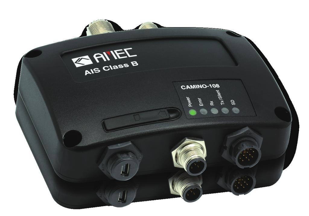
8 1 System Overview 1.1 Product Description The AMEC CAMINO-108 AIS Class B Transponder series is perfect for smaller vessels, where the complexity of a Class A Transponder is not necessary. It transmits the vessels dynamic and static information, as well as receiving all AIS targets within 20 miles of the boat, typically. Using the built-in GPS receiver, the CAMINO-108 determines position, speed and course, and once this is combined with other navigational information, it is automatically transmitted without any user interaction. When received by other vessels and coast stations, the data built up will provide a live graphical display of traffic in the area. The CAMINO-108 has been engineered for flawless integration with navigation systems, and supports NMEA2000 and NMEA0183 communications, and its output meets IEC and related standards. The CE/BSH approved CAMINO-108 also features USB connectivity and an optional Wi-Fi interface (CAMINO-108W). The SD card slot in the CAMINO-108 can be quickly and easily used as a data recorder, enabling the capture of all messages - to assist in system and safety monitoring, including incident investigation. The recorded data is logged and stored on the SD card when fitted. An optional switch box enables Silent mode allowing the user to stop the broadcast of static and dynamic information on occasions where either privacy or security is required. 1


9 CAMINO-108 CAMINO-108W Front Front Back Back 2
10 1.2 Equipments in the Box Upon receiving the product please verify items in the box. If any is missing, please contact your local AMEC representative immediately. 3
11 1.3 External Connections 4
12 1.4 What is AIS? The Automatic Identification System (AIS) is a Very High Frequency (VHF) radio broadcasting system that transfers packets of data over the VHF data link (VDL) and enables AIS equipped vessels and shore-based stations to exchange identification information and navigational data. Ships with AIS transponders continually transmit their ID, position, course, speed and other data to all nearby ships and shore stations. Such information can aid greatly in situational awareness and provide a means to assist in collision avoidance. AIS equipment is standardized by ITU, IEC, IALA and IMO and is subject to approval by a certification body. The following AIS devices have been developed for variant applications. AIS Class A: mandated by the IMO for vessels of 300 gross tonnages and upwards engaged on international voyages, cargo ships of 500 gross tonnages and upwards, as well as passenger ships. It transmits typically on 12.5 watt output power. AIS Class B: provides limited functionality and is intended for non-solas commercial vessels and recreational vessels. It transmits typically on 2 watt output power. AIS Receiver: only receives AIS signal and it does not have transmitter to send out AIS signal. Suitable for recreational vessel that does not want to send out its vessel information. 5
13 AIS Base Station: is provided by aids-to-navigation authorities to enable the ship to shore / shore to ship transmission of information. Networked AIS Base Stations can assist in providing overall maritime domain awareness. AIS AtoN (Aids to Navigation): provides an opportunity to transmit position and status of buoys and lights through the same VDL, which can then show up on AIS-ready devices within the range. AIS SART: Search and Rescue Transmitter using AIS can be used to assist in determining the location of a vessel in distress. It is typically used on life rafts. AIS on Search and Rescue (SAR) Aircraft: used on airplanes and helicopters to assist search and rescue operation. 6
14 1.4.1 Class A vs. Class B AIS A brief comparison of class A and class B AIS is illustrated in the following table. CAMINO-108 is a class B AIS transponder. Table 1-1 Comparison of Class A and Class B Type of AIS Class A AIS Class B AIS Communication Protocol Transmit Power and range IMO Mandate Reporting rate dynamic data SOTDMA (Self-organizing) CSTDMA (Carrier-Sense) 12.5w (25 NM expected) 2w (5-7 NM expected) Mandatory for all SOLAS compliant vessels Higher (transmission up to every 2 sec) No mandate Lower (transmission up to every 30 sec) AIS data presented Static, Dynamic, Voyage Static and Dynamic data Applications Commercial vessels, fishing boats, working boats, passenger boats with more than 12 passengers Recreational vessels and small fishing boats 7
15 1.4.2 AIS Message Types Class B AIS broadcasts following message types: Static Data: MMSI Dynamic Data: Vessel name Vessel call sign Type of ship Ship dimensions / GPS antenna location Position of the vessel Course over ground (COG) Speed over ground (SOG) True heading AIS Report Rate Class B AIS broadcasts ship dynamic data per following reporting interval. Besides, ship static data will be broadcasted every 6 minutes. Ship Condition Ship not moving faster than 2 knots Ship moving faster than 2 knots Nominal Reporting Interval 3 Minutes 30 Seconds 8
16 2 Installation 2.1 Installation Procedures Please familiarize the manual content before begin installation. Depending on your hardware configuration, use the following recommended steps for installation. 1) Mount the transponder unit to an appropriate location 2) Install VHF antenna 3) Install GPS antenna 4) Connect antenna cables to the transponder 5) Connect to a chartplotter via NMEA0183 or NMEA2000 interface if applicable 6) Make silent mode connection if applicable (optional external switch needed) 7) Connect to an appropriate power source (12V / 24V DC, 2A) 8) Power On the power source (which turns on the transponder unit) 9) Program MMSI and vessel information into the device using configuration software before installation (please refer to chapter 3) 10) Perform LED checking and system functional test 9
17 2.2 Mounting Transponder Main Unit The following guidelines should be noticed when selecting the environment to install your AMEC CAMINO-108: Do not install the AIS transponder in a flammable or hazardous atmosphere such as in an engine or generator room or close to fuel tanks. Installation of the transponder should be undertaken in a safe environment without being exposed to any splashing water or rain. There should be adequate space around the AIS transponder for routing of cables. See figure below for details of the AIS transponder dimensions. The safe distance of the transponder to any magnetic compass is at least 0.55m. The operating temperature is between -15 C and +55 C. The AIS transponder can be installed and mounted on flat surface, or it can be mounted on wall with the four self tapping screws supplied. The device should be mounted in a location where the indicators can readily be observed as these indicators deliver relevant information on the status of the AIS transponder. 10
18 Figure 1 Mounting the transponder 11
19 2.3 VHF/GPS Antenna Installation The quality and positioning of the antenna are the most important factors dictating AIS performance. It is recommended that a VHF antenna with omnidirectional vertical polarization be specifically tuned for AIS operation band. Since the range of VHF signals is largely decided by line of sight distance, the VHF antenna should be placed as high as possible and at least 5 meters away from any constructions made of conductive materials. It is recommended to keep the VHF antenna at least 3 meters away from the GPS antenna. Ensure the GPS antenna is not within the transmitting beam of other high power transmitting antenna. 5 VHF Antenna Ensure a free 360 horizon with a vertical observation of 5. The recommended horizontal distance between GPS antennas and other antennas is 3m. Other transmitting antenna Other VHF Antenna The recommended vertical distance between antennas is 2m. The recommended horizontal distance between antennas is 10m. Figure 2 VHF/GPS antenna locations WARNING: The safe distance from a transmitting VHF antenna is 60cm. 12
20 2.4 GPS Antenna Location The ANT-21 GPS antenna must be installed where it has a clear view of the sky, so that it may access the horizon freely with 360 degrees, with a vertical observation of 5 to 90 degrees above the horizon as illustrated in the figure above. Enter the GPS antenna location data in SHIP SETTING in the configuration utility after the installation Following is the GPS antenna location offsets. D C A Figure 3 B GPS antenna location When connecting the cables, take note of the following precautions. Bending cables may cause damages to the inner wires and impair overall the performances. Each coaxial cable should be set up separately and can only be set up in a single cable tube. Insulation on connector port of the coaxial cable should be considered. 13
21 2.5 Connecting Power and Data Cable Connecting the CAMINO-108 to external power source and data equipments are illustrated in diagram below. Figure 4 Wiring instructions When wiring NMEA0183 to AIS-ready equipment, please refer to your equipment manual first. CAMINO-108 supports two NMEA0183 ports and each can be configured to 4800, 9600, or baud rate independently. The default baud rate for both ports is Use the provided configuration utility to change baud rates. CAMINO-108W supports only one configuration baud rate configuration for Tx/Rx on NMEA0183 port #2. 14 (Tx Switch Box)
22 2.6 Connecting with NMEA0183 Devices CAMINO-108 supports two NMEA0183 ports and each NMEA 0183 port s transmitting and receiving interface can be configured to 4800, 9600, or baud rate independently. The default baud rate for both ports is bps. Use the provided configuration utility to change baud rates. Typically the high speed setting is intended primarily for chart plotter connection, while the low speed setting can be used to connect to other NMEA0183 devices. The ports have bidirectional multiplexing, which means any received messages via one port are automatically transmitted to the other port and vice-versa. Figure 5 Multiplexing with NMEA0183 ports 15
23 CAMINO-108 NMEA0183 RXP RXN TXP TXN External NMEA0183 Device (RS422) (Chartplotter) TXP TXN RXP RXN Figure 6 NMEA0183 Connection illustration NMEA0183 Signal (CAMINO-108) Signal Direction (CAMINO-108) External NMEA0183 Device Receive + (RXP) Input n/a Receive (RXN) Input n/a Transmit + (TXP) Output Data Input + (RXP) Transmit (TXN) Output Data Input (RXN) 16
24 CAMINO-108 NMEA0183 RXP RXN TXP TXN External NMEA0183 (GPS Source) TXP TXN External NMEA0183 (Chartplotter) RXP RXN Figure 7 NMEA0183 Multiplexing Connection NMEA0183 Signal (CAMINO-108) Signal Direction (CAMINO-108) External NMEA0183 Devices Receive + (RXP) Input Data Output + (TXP) Receive (RXN) Input Data Output - (TXN) Transmit + (TXP) Output Data Input + (RXP) Transmit (TXN) Output Data Input (RXN) 17
25 2.7 AIS Silent Mode Connection If you require Silent Mode feature, it is possible to connect an external toggle switch to CAMINO-108. Connect the toggle switch between the pink and light blue wires to enable Silent Mode function, as depicted in Figure 4. An optional external Tx Switch Box (part number SB-181) is available from AMEC to support silent mode implementation. You can use SB-181 as toggle switch to turn on/off the AIS transmission. 2.8 Connection to NMEA2000 Network NMEA 2000 is the latest marine standard for data communication between marine instruments. With a NMEA 2000 network onboard, a faster data throughput, better transmission reliability and easy data sharing can be realized. The CAMINO-108 is equipped with NMEA2000 interface with LEN=1. AIS targets received by the transponder now can be easily displayed on your chart plotter when both are connected to a NMEA2000 network with a compatible T-connector and drop cable available by your local service partner. 2.9 Connecting to Power Supply The CAMINO-108 requires a 12V or 24V DC power supply (9.6 to 31.2V) capable of supplying 2A peak current. The red wire and the black wire on the 12 pin cable are used to connect the power supply s positive and negative terminals. Practically, it is suggested to use the fuse panel before connecting directly to the battery/power supply. 18
26 3 Configuring Your CAMINO-108 The AMEC AIS Configuration software enables the user to set up the transponder by entering your own ship s information. It also provides the facilities to monitor and diagnose your transponder from your PC/Laptop. The AMEC AIS Configuration software can be found on the CD supplied. To install the configuration software, follow the installation instructions below. Open the AMEC AIS Configuration file on the CD and click on the setup icon to start the installation process. Follow the on screen instructions to complete the installation and check the checkbox to start the AMEC AIS Configuration Software at the end of the installation. 3.1 Establish Connection to your PC Serial Port Connection The USB driver has to be installed before linking the transponder to your PC. A PC/laptop can also be a convenient platform to display AIS targets with compatible software like the AIS Viewer supplied. Required Items USB Driver (included in the software CD) USB cable (included in the box) PC/Laptop with Windows operating system (not included). CAMINO-108 USB Driver supports Windows XP, Windows Vista, Windows 7 and Windows 8. One available USB port on PC/Laptop Available CD-ROM drive on PC/Laptop 19

27 USB Driver Installation With the transponder power on and the USB cable attached, plug in the USB cable to the PC/Laptop. A new hardware found prompt will show up. Follow the on screen instructions and assign the correct file path of the USB driver to complete the installation. You can also install the USB driver via the Device Manager in the Control Panel. Detailed USB driver installation instructions including Windows 8 platform are supplied on the CD with the USB driver. Once the USB driver is installed, launch the Configuration Software, select Option in the menu bar, then Connection, and serial port. There are 2 options to connect the software with your transponder: Auto: The system will scan all connected ports and their available baud rates and establish connection automatically. Manual: Configure baud rate and port manually. The default baud rate is To determine serial port with which the transponder is connected, please refer to Appendix in this manual. Click on Connect, to connect the Configuration Software with your transponder. Figure 8 Serial port connection 20

28 3.1.2 Wireless Connection (only for CAMINO-108W) Figure 9 Wi-Fi connection for CAMINO-108W For CAMINO-108W, the connection between the Configuration Software and your transponder can also be established wirelessly. Please refer to 4.4 Wi-Fi Configuration about how to access CAMINO-108W from your PC as a hotspot. After your PC is wirelessly connected with the transponder, go to Option in the menu bar, then Connection, and Wi-Fi. The IP address and Port are already preprogrammed to fit CAMINO-108W s configuration. Click on Connect, to connect the Configuration Software with your transponder. 3.2 Programming your vessel data After the transponder is successfully connected with the Configuration Software, click on the STATIC DATA tab. You will require the following information in order to configure your AIS transponder: Vessel name: limited to 20 characters Call sign: limited to 7 characters MMSI: Enter your MMSI (Maritime Mobile Service Identity) number Vessel type: choose your ship type from the drop down list 21

29 Ship dimensions: Enter the vessel dimensions and position of your GPS antenna installation WARNING: The MMSI number can only be entered once. Be sure to enter the correct MMSI number, as it cannot be corrected if entered incorrectly. Figure 10 Static Data Setting 22
. (3) GPS mode: the option Altitude higher than 500m enables GPS positioning at an altitude over 500m. The default setting is At sea level.")
30 3.3 Transceiver Setting (1) To disable DSC monitoring function, select the OFF button. The default setting is ON (DSC enabled). (2) To disable the GPS output, check and select the OFF button. The default setting is 5 seconds (GPS enabled). (3) GPS mode: the option Altitude higher than 500m enables GPS positioning at an altitude over 500m. The default setting is At sea level. Figure 11 Transponder Setting 23
31 3.4 Baud Rate Setting (1) Click on BAUD RATE tab. (2) The default baud rate for NMEA is Enter the baud rate of connected devices. For NMEA 0183, CAMINO-108 supports baud rates 38400, 9600 and The both NMEA0183 ports of CAMINO-108 can be configured individually. For CAMINO-108W, only the first NMEA port has individual configuration. The 2 nd NMEA port shares the same baud rate. Click on to confirm and complete the setting. Figure 12 Baud Rate Setting CAMINO-108 (left) and 108W (right) 24
32 (3) To read the device information, click on. A Configuration Report will pop-up in Notepad or an application that is associated for text file format. Figure 13 Configuration Report 25

33 3.5 Diagnosis Functions The second part of the AMEC AIS Configuration software utility features diagnosis functions. This function should be performed only after the device and antennas are all fully installed. Click on the Diagnosis tab to proceed for System Check, GPS Status, and Data Log. Figure 14 System Check 26

34 3.5.1 System Check The System Check function can be used to check the Firmware Version, Serial Number, MMSI, GPS status, AIS TX report count, and AIS RX report count of the device. This function starts upon the connection of the device when powered on. To recheck all status, click on button. Figure 15 System Check 27

35 3.5.2 GPS Status This tab shows the GPS status and the connectivities of all GPS satellites being used. Figure 16 GPS Status 28

36 3.5.3 Data Log The log shows the collected AIS data log from the device. You may save or clear the current collected log. Figure 17 Data Log 29
37 4 GET STARTED 4.1 Start up the Transponder The transponder will start up whenever the connected power source is ON. It will operate automatically if the transponder has been properly configured using the Configuration Software and GPS/VHF antennas are also properly installed. Normally the transponder should transmit its own ship positions every 30 seconds or 3 minutes depending on the moving speed. It should also receive other vessels information in the vicinity. The operation status of the transponder can be checked from the LED lights on the unit. Description of the LED indications is provided in the following section. 30
38 4.2 LED Indicators Indicator Light Description Power Green The green LED indicates that the transponder has been powered up correctly. Error Red The red LED indicates that MMSI is not correctly set or the system has a BIIT error. Please refer to 4.5 for more information about BIIT. Rx Green The green LED flashes when the transponder is receiving AIS data. Tx/Silent Green/Red The LED blinks green when the transponder is transmitting AIS data. When the device is set in silent mode, the LED turns on red steadily. SD Wi-Fi (108W only) Green (Flashing/Steady) Green Flashing: SD card is being accessed. Steady: SD card is full. Replace with another empty SD card or delete files to obtain free spaces. The green LED indicates an active Wi-Fi traffic 31

39 4.3 SD Card Data Logging The CAMINO-108 records voyage data onto a SD card in.txt format. The compatible SD card types are listed as followed: Standard SD with maximum 2GB size Standard SDHC with maximum 32GB size Supported data format: FAT12/16 by SD, FAT32 by SDHC Please insert the SD card into the slot as shown below before powering on the transponder. After the transponder is switched on, it will commence logging voyage data and indicates the writing process by flashing the green SD LED indicator. The log files have naming convention of AIS_XXXXXX.txt with increment from to Entry in the log file is vessel s GPS sentence in IEC61162 format. When memory is full, SD LED light indicator will turn steady green to remind user to replace the SD card. No further data logging will take place before new saving capacity is available or replaced with an empty SD card. Removing SD card from the transponder stops data logging immediately, and the SD LED will turn off. Make sure the device s power is off before inserting SD card. Figure 18 Inserting SD memory card 32

 Security Encryption: Any device being used to connect to the unit via Wi-Fi should support WPA-PSK with TKIP data encryption If requested by your device for an IP address")
40 4.4 Wi-Fi Configuration (CAMINO-108W only) Installation of Wi-Fi antenna is straight forward. Screw on the antenna firmly and then raise up the antenna. Figure 19 Transponder with Wi-Fi antenna connected The information below details the information required for connecting the CAMINO-108W to another device using Wi-Fi. SSID (Service Set Identifier): The SSID for the CAMINO-108W is AIS-B-NNNN where NNNN is the last 4 digits of the units serial number (printed on the label on the side of the unit) Security Encryption: Any device being used to connect to the unit via Wi-Fi should support WPA-PSK with TKIP data encryption If requested by your device for an IP address or port number, use the following details 33
41 IP Address Port 3333 Password: The Wi-Fi Network key is The SSID, security encryption and Network key (password) are non-configurable and pre-set at the factory. 4.5 Built-in Integrity Test (BIIT) With BIIT (Built in Integrity Test) function, the CAMINO-108 is constantly monitoring and testing the integrity of the AIS transponder. Should an abnormal condition be detected within the device, the Error LED will alert with flashing red light. Abnormal conditions may include situations like the followings: Antenna VSWR exceeding the maximum allowed level (Error LED flash) MMSI not set (Error LED steady on) Background noise level exceeds allowable threshold (-77dBm) (Error LED flash) GPS is unable to gain lock (3D fixed) after 30 minutes of losing GPS signal (Error LED flash) Low input power (< 8.6 V DC) (Error LED flash) 34


42 4.6 AIS Viewer Description The AIS Viewer is a complementary charting software supplied with your CAMINO-108 transponder purchase. The software installation file and its user manual can be found in the provided CD-ROM. This powerful tool allows users to display AIS targets either on a basic line map or in an alphanumeric view. It transforms your PC to a user-friendly AIS data logger and can trace other vessels with voyage track. Besides, the software offers various safety features to help users be alerted during their voyage. Once the program is installed, you can establish a connection to PC either automatically or manually by assigning the COM port and baud rate. Please notice that before trying to connect to PC, you should quit the Configuration Software or vice-versa. The transponder can only establish connection to one software at a time. The AIS CPA/TCPA setting can be configured via AIS Viewer. Figure 20 AMEC AIS Viewer 35

43 4.7 Introducing AMEC AIS App The AMEC AIS App is a complimentary App with the purchase of an AMEC AIS CAMINO-108W transponder. The App enables users to monitor the surrounding AIS traffics on your smart phone or tablet PC wirelessly. The AIS targets are displayed clearly in radar view or in an alphanumeric vessel list format. Data of own vessel can be traced in real time. The App also offers various safety features to help users be alerted during their voyage. The AMEC AIS App is now available on Google Play for Android mobile devices. The ios version will follow in the near future. Legal Apple, the Apple logo, iphone, ipad, itunes, and ios are trademarks of Apple Inc., registered in the U.S. and other countries. itunes Store is a service mark of Apple Inc., registered in the U.S. and other countries. App Store are trademarks of Apple Inc. Google, the Google logo, Android, and Google play are trademarks of Google Inc., registered in the U.S. and other countries. 36
44 5 SPECIFICATIONS 5.1 Product Specifications APPLICABLE STANDARDS IEC Ed. 2, 2010 IEC Ed. 1, 2003 IEC Ed. 3, 2007 IEC Ed. 4, 2002 IEC Ed. 1, 1998 ITU-R M , 2010 VHF TRANSPONDER Frequency Range MHz ~ MHz Channel Bandwidth 25 KHz Modulation GMSK / FM Data Rate 9,600 bps Number of AIS Transmitter 1 Number of AIS Receiver 2 (one time-shared between AIS and DSC) Number of DSC Receiver 1 (time-shared between AIS and DSC) AIS Channel 1 CH 87B ( MHz) AIS Channel 2 CH 88B ( MHz) Tx Power Output 2 Watt (33 dbm ± 1.5 db) Rx Sensitivity < % PER DSC RECEIVER Modulation 1,300 Hz / 2,100 Hz FSK Data Rate 1,200 bps ± 30 ppm Spurious Response Rejection 70 db for -104 dbm; BER 1 % Blocking 84 db for -104 dbm; BER 1 % 37
45 GPS RECEIVER (integrated) Receiving Channels 50 channels Accuracy IEC compliant Output Rate 1 Hz POWER SUPPLY Supply Voltage 12V / 24V DC, 2A Power Consumption (108) Typically less than 3W 12V DC Power Consumption (108W) Typically less than 4W 12V DC CONNECTION INTERFACE GPS Antenna Connector TNC (Female) VHF Antenna Connector PL-259 (Female) NMEA2000 Standard connector LEN=1 Silent Mode Setting Set by the dedicated pins in the 12-pin cable USB Mini-B type, waterproof NMEA 0183 (RS-422) Support two NMEA0183 interfaces Baud rate configurable (default 38,400 bps) Separate Tx/Rx baud rate Standard IEC / IEC sentences Wireless Connection IEEE b/g/n (CAMINO-108W only) ENVIRONMENTAL Operating Conditions IEC protected category Operating Temperature -15 C ~ 55 C Waterproof IPX2 PHYSICAL Width 128 mm (5.51 inch) Height 36 mm (1.97 inch) 38
46 Depth 88 mm (7.87 inch) (exclude connector) Weight 250 g SOFTWARE TOOL AMEC AIS Configuration PC configuration utility AMEC AIS Viewer AIS Viewer for PC ANT-21 GPS Antenna (optional) Cable integral 10m RG-58 cable plus mounting bracket Supply Voltage 3.3V 39
47 5.3 Dimensions (GPS antenna is an optional item) 40
48 5.4 NMEA 2000 PGN Information Transmit PGN Description ISO Acknowledgment ISO Request ISO Address Claim PGN List - Transmit PGN's group function Product Information AIS Class A Position Report AIS Class B Position Report AIS Class B Extended Position Report AIS Aids to Navigation (AtoN) Report AIS DGNSS Broadcast Binary Message AIS UTC and Date Report AIS Class A Static and Voyage Related Data AIS Addressed Binary Message AIS Acknowledge AIS Binary Broadcast Message AIS UTC/Date Inquiry AIS Addressed Safety Related Message AIS Safety Related Broadcast Message AIS Interrogation AIS Assignment Mode Command AIS Data Link Management Message AIS Class A Position Report 41
49 AIS Group Assignment DSC Call Information AIS Class B CS Static Data Report, Part A AIS Class B CS Static Data Report, Part B Receive PGN Description ISO Acknowledgment ISO Request ISO Address Claim 42
50 6 TROUBLESHOOTING The transmitting LED (Green color) is not illuminated, why? The transmitting interval of a Class B transponder is 3 minutes if the speed of the vessel is less than 2 knots. If the speed exceeds 2 knots, the transmitting interval will be 30 seconds. For each transmission, the channel indicator will flash once quickly. The green light from the Tx indicator could be missed if not observed carefully. For AIS transmitting, GPS information from GPS antenna is required. Without GPS information, AIS will not transmit AIS signal. Please check if your GPS antenna is connected and setup correctly. CAMINO-108 receives AIS signals normally, but no one in the surrounding can see me, why? AIS Class B transmission range limitation: an AIS Class B transponder transmitting range of 5-7 miles in perfect conditions. The AIS receiver in the transponder will typically see Class A vessels that are miles away or even more in excellent conditions. The major reason is that all AIS Class B transponders transmit at 2 watts vs. the 12.5 watts that Class A transponders typically use. This difference in power impacts on the transmission range of each transponder type. For this reason, it is quite possible that Class A vessel can be seen, but Class B vessel might not be seen. VHF antennas interference: if you are using a dedicated AIS/VHF antenna for your transponder, be sure that it is placed at least 6 ft (1.83 m) away from other VHF antennas or vertical metal objects and ideally install the antenna on a different vertical plane from other VHF antennas. In several tests, mounting 43
51 two VHF antennas next to another typically reduces the transmitting range to both antennas by 50-70%. GPS is not fixed: If your GPS antenna is not connected or setup correctly, your transponder will see other vessels fine, but you will not be sending out your vessel position. All AIS transponders need a good GPS fix before it can send out any type of transmission. The color and state of the LEDs on the transponder indicate if the unit is in transmission mode or not. The location of VHF antenna is directly related to AIS transmitting range. The VHF antenna should be installed at mast as high as possible. The silent mode (Tx off) on CAMINO-108 is not working, why? Silent mode can be configured on CAMINO-108 by using the wires at 12-pin connector. Even though my CAMINO-108 is transmitting, why do some vessels with AIS take a long time to see my vessel name or not see it at all? AIS Class B users should keep in mind that Class B transponders do not broadcast position updates as often as Class A commercial transponders. As with Class B transponders, the full static information, such as vessel s names, the transmission is broadcasted every 6 minutes; however, MMSI and dynamic information, such as position, update will only be sent out every 3 minutes if the vessel is moving slower than 2 knots. To add to this, if the receiving party is using non-standard dual channel receiver (a single channel receiver), then in perfect conditions, the receiver will get your full static information every 12 minutes and your MMSI and dynamic information every 6 minutes if you are moored. 44
52 No data is being received by chart plotter, why? Please check that the power supply is connected correctly at CAMINO-108. Please check that the power supply is 12V or 24V with sufficient current capacity (no less than 2A). Please make sure that the connections between CAMINO-108 to the chart plotter are correct. My MMSI is being received by other vessels but my vessel name is not shown on their chart plotter or PC, why? Older software and AIS displays may not be fully compatible with Class B transponders. In some of these cases, older equipments might only have Class B vessel show up on their displays with just MMSI number without the vessel name. This is usually due to the receiving device not knowing how to process the Message 24 static data from Class B transponders. Please contact the chart plotter maker and ask for software upgrades (for these older chart plotters) to resolve this issue. The Red Error LED indication at CAMINO-108 is illuminated, why? The unit may not have a valid MMSI. Please check if the AIS transponder is correctly entered with a valid MMSI. Please make sure that both VHF and GPS antennas and their cables are working properly and not damaged. If you still encounter difficulties to set up or operate CAMINO-108 correctly, please to service@alltekmarine.com for further instructions. 45
53 7 ABBREVIATIONS AIS COG CPA CSTDMA DSC ECS ETA GPS IMO MMSI SOG TCPA TDMA UTC VHF VTS Automatic Identification System Course Over Ground Distance to Closest Point of Approach Carrier-Sense Time Division Multiple Access Digital Selective Calling Electronic Chart System Estimated Time of Arrival Global Positioning System International Maritime Organization Maritime Mobile Service Identity Speed Over Ground Time to Closest Point of Approach Time Division Multiple Access Coordinated Universal Time Very High Frequency Vessel Traffic Services 46
54 8 FCC INTERFERENCE STATEMENT NOTE: This equipment has been tested and found to comply with the limits for a Class A digital device, pursuant to part 15 of the FCC Rules. These limits are designed to provide reasonable protection against harmful interference when the equipment is operated in a commercial environment. This equipment generates, uses, and can radiate radio frequency energy and, if not installed and used in accordance with the instruction manual, may cause harmful interference to radio communications. Operation of this equipment in a residential area is likely to cause harmful interference in which case the user will be required to correct the interference at his own expense. This device complies with Part 15 of the FCC Rules. Operation is subject to the following two conditions: 1) This device may not cause harmful interference, and 2) This device must accept any interference received, including interference that may cause undesired operation. Any changes or modifications not expressly approved by AMEC for compliance could void of the user's authority to operate the equipment. 47
55 9 RF Exposure Warning WARNING: This device generates and radiates RF electromagnetic energy and must be installed and operated according to the instructions contained in this manual. Failure to do so may result in product malfunction and/or exposure to potentially harmful levels of radio frequency radiation. WARNING: Never operate this device unless it is properly connected to a VHF antenna. To maximize performance and minimize human exposure to RF energy, always mount the antenna at least 3m from the device. The system has a Maximum Permissible Exposure (MPE) radius of 60cm from the antenna. This has been determined assuming the maximum power of the transmitter and using a standard half-wave monopole VHF antenna with a maximum gain of 3dBi and termination impedance of 50 ohms. When installing the antenna and operating the equipment consider the following: The antenna should be mounted at a minimum vertical distance of 5m above the deck in order to meet international safety directives on Maximum Permissible Exposure (MPE). Failure to adhere to these limits could expose persons within the 60cm radius to RF radiation in excess of the recommended MPE limits. Higher gain VHF antennas will require a larger MPE radius. Do not operate the unit when anyone is within the MPE radius of the antenna. The antenna should not be co-located or operated in conjunction with any other transmitting antenna. 48
56 DECLARATION OF CONFORMITY Hereby, Alltek Marine Electronics Corp. (AMEC) declares that this CAMINO-108 is in compliance with the essential requirements and other relevant provisions of Directive 1999/5/EC. AMEC WORLDWIDE WARRANTY Limited warranty Subject to the terms, conditions and limitations set forth in this Worldwide Limited Warranty (hereinafter the Warranty ), AMEC warrants that its products, when properly installed and used, will be free from defects in material and workmanship for a period of twelve (12) months, from the date of first purchase (the Warranty Period ) For the purposes of this warranty, date of first purchase means the date that the product was purchased by the first retail customer, or by the institutional customer, or in the case of a product installed on a new vessel or any other marine related platform by a certified AMEC original equipment manufacturer (a AMEC OEM ), the date that such vessel was purchased by the first retail customer. AMEC will, at its sole option, repair or replace any defective products or components returned during the Warranty Period in accordance with the terms, conditions and limitations set forth below. Such repairs or replacement will be the sole remedy of the customer under this Warranty. Standard Warranty Service To qualify for standard warranty service the product must be returned to a AMEC-certified service agent (i) within the Warranty Period, and (ii) within thirty (30) 49
57 days of the alleged product failure. Any products returned must be securely packaged and sent pre-paid and insured to AMEC or to a AMEC-certified service agent. All products returned must be accompanied by a copy of the original sales receipt to be eligible for standard warranty service. Other conditions This Warranty is fully transferable provided that you furnish the original proof of purchase to the AMEC -certified service agent. This Warranty is void if the seal label is removed or defaced. THE LIABILITY OF AMEC TO A CUSTOMER UNDER THIS WARRANTY, WHETHER FOR BREACH OF CONTRACT, TORT, BREACH OF STATUTORY DUTY OR OTHERWISE SHALL IN NO EVENT EXCEED AN AMOUNT EQUAL TO THE TOTAL PURCHAE PRICE OF THE PRODUCT GIVING RISE TO SUCH LIABILITY AND IN NO EVENT SHALL AMEC BE LIABLE FOR SPECIAL, INCIDENTAL, CONSEQUENTIAL OR INDIRECT DAMAGES OR LOST OF GOODWILL, REPUTATION, LOSS OF OPPORTUNITY OR INFORMATION, DATA, SOFTWARE OR APPLICATIONS. In the event that any term or provision contained in this Warranty is found to be invalid, illegal or unenforceable by a court of competent jurisdiction, then such provision shall be deemed modified to the extent necessary to make such provision enforceable by such court, taking into account the intent of the parties. All AMEC products sold or provided hereunder are merely aids to navigation. It is the responsibility of the user to exercise discretion and proper navigational skill independent of any AMEC product. 50

58 Appendix: How to Determine Serial Port If you PC/laptop does not have available serial port, you may use a RS232-to-USB adapter. To find out the proper serial port for connection use the following instructions. Windows 7 or VISTA version: Click on Start Select Control Panel Select Device Manager Click Port (COM&LPT) Windows 8 and 8.1: Click (W)* + I and then click on Control Panel Select Device Manager Click Port (COM&LPT) * means Windows button Serial port number 51
59 Alltek Marine Electronics Corporation 5F, No. 37, Ji-Hu Road, Neihu District, Taipei, 11492, Taiwan Tel: Fax: service@alltekmarine.com Website:
User s Manual COPYRIGHT DISCLAIMER
 COPYRIGHT The entire contents of this instruction manual, including any future updates, revisions, and modifications, shall remain the property of AMEC at all times. Unauthorized copies or reproduction
General Information Manual Edition 1.14
 General Information Manual Edition 1.14 i. Copyright The entire contents of this instruction manual, including any future updates, revisions, and modifications, shall remain the property of AMEC at all
Manual Revision: Version 1.06
 COPYRIGHT The entire contents of this instruction manual, including any future updates, revisions, and modifications, shall remain the property of AMEC at all times. Unauthorized copies or reproduction
General Information Manual Edition 1.04
 General Information Manual Edition 1.04 i. Copyright The entire contents of this instruction manual, including any future updates, revisions, and modifications, shall remain the property of AMEC at all
General Information Manual Edition 1.08
 General Information Manual Edition 1.08 i. Copyright The entire contents of this instruction manual, including any future updates, revisions, and modifications, shall remain the property of AMEC at all
CAMINO-108S. AIS Class B with Integrated Splitter USER MANUAL
 CAMINO-108S AIS Class B with Integrated Splitter USER MANUAL COPYRIGHT The entire contents of this instruction manual, including any future updates, revisions, and modifications, shall remain the property
Manual Revision: Version 1.30
 COPYRIGHT The entire contents of this instruction manual, including any future updates, revisions, and modifications, shall remain the property of AMEC at all times. Unauthorized copies or reproduction
CAMINO-108S. AIS Class B with Integrated Splitter USER MANUAL
 CAMINO-108S AIS Class B with Integrated Splitter USER MANUAL COPYRIGHT The entire contents of this instruction manual, including any future updates, revisions, and modifications, shall remain the property
NSPL-500. AIS/VHF antenna splitter. User Manual ENGLISH.
 NSPL-500 AIS/VHF antenna splitter User Manual ENGLISH www.bandg.com www.simrad-yachting.com www.lowrance.com Preface As Navico is continuously improving this product, we retain the right to make changes
Thank you for buying this AIS antenna splitter.
 Thank you for buying this AIS antenna splitter. This product has been engineered to offer you the highest level of performance and durability and we hope that it will provide many years of reliable service.
Watcheye S AIS Splitter. manual
 Watcheye S AIS Splitter manual Thank you for buying this AIS antenna splitter. This product has been engineered to offer you the highest level of performance and durability and we hope that it will provide
Thank you for buying this AIS receiver.
 Thank you for buying this AIS receiver. This product has been engineered to offer you the highest level of performance and durability and we hope that it will provide many years of reliable service. We
HIGH PERFORMANCE MARITIME. em-trak S100 PRODUCTS. Antenna splitter. Product Manual. High Performance Maritime Products
 em-trak S100 MARITIME PRODUCTS HIGH PERFORMANCE Antenna splitter Product Manual High Performance Maritime Products www.em-trak.com 201-0206:3 Contents 1 - Notices...1 1.1 - Safety warnings...1 1.2 - General
COPYRIGHT DISCLAIMER. Contact us at:
 COPYRIGHT The entire contents of this instruction manual, including any future updates, revisions, and modifications, shall remain the property of AMEC at all times. Unauthorized copies or reproduction
Smartfind M15, M15S & M15SW AIS Receiver User Manual
 Smartfind M15, M15S & M15SW AIS Receiver User Manual General Information i. Copyright The entire contents of this instruction manual, including any future updates, revisions, and modifications, shall remain
AIS 300 Installation Instructions
 Use these instructions to install the Garmin AIS 300 Automatic Identification System (AIS) Class B receiver device. Compare the contents of this package with the packing list on the box. If any pieces
KS-200A/B. ˵à Êé. AIS Class B Transponder KS-200A AIS Receiver KS-200B
 R KS-200A/B KS-200A/B ˵à Êé OPERATOR`S MANUAL AIS Class B Transponder KS-200A AIS Receiver KS-200B SAFETY INSTRUCTIONS Safety Instructions for the Operator WARNING Do not open the equipment. Only qualified
LD2342 USWM V1.6. LD2342 V1.4 Page 1 of 18
 LD2342 USWM V1.6 LD2342 V1.4 Page 1 of 18 GENERAL WARNINGS All Class A and Class B marine Automatic Identification System (AIS) units utilize a satellite based system such as the Global Positioning Satellite
Sales & Marketing: Version 1.01
 User s Manual II COPYRIGHT The entire contents of this instruction manual, including any future updates, revisions, and modifications, shall remain the properties of AMEC at all times. Unauthorized copies
ANTENNA SpliTTEr. Zero loss active VHF antenna splitter. I N s t r u c t i o n m a n u a l
 ANTENNA SpliTTEr Zero loss active VHF antenna splitter I N s t r u c t i o n m a n u a l w w w. g m e. n e t. a u Thank you for buying this AIS antenna splitter. This product has been engineered to offer
Installation & Quick Start Guide CLB2000 Class B AIS Transponder
 Installation & Quick Start Guide CLB2000 Class B AIS Transponder QUICK START CLB2000 - VR1.01 1. Introduction Congratulations on the purchase of your CLB2000 Class B AIS Transponder. It is recommended
AIS Training. AIS Technology in Digital Yacht Products Explained. Digital Yacht Ltd TEL
 AIS Training AIS Technology in Digital Yacht Products Explained Digital Yacht Ltd www.digitalyacht.co.uk TEL + 44 1179 554474 What is AIS? The Automatic Identification System (AIS) is the biggest advance
AIT2000 CLASS B AIS TRANSPONDER
 IMPORTANT NOTE The USB cable of the AIT2000 is designed to be used for configuring/programming the unit during installation and not for permanent connection to the boat s Navigation PC. If you intend to
Installation & Quick Start Guide AIT2000 Class B AIS Transponder
 Installation & Quick Start Guide AIT2000 Class B AIS Transponder QUICK START AIT2000 - VR1.01 1. Introduction Congratulations on the purchase of your AIT2000 Class B AIS Transponder. It is recommended
Installation and Quick Reference Guide. Disclaimer and warranty 2. Contents of this box 2. Brief background to AIS 3.
 AI3000 AIS Receiver ai3000vf rev 6b Installation and Quick Reference Guide Contents Page Number Disclaimer and warranty 2 Contents of this box 2 Brief background to AIS 3 Introduction 3 Installing the
Class B AIS Transceiver Mariner X2 Automatic Identification System
 Class B AIS Transceiver Mariner X2 Automatic Identification System INSTALLATION MANUAL Version 1.4 Thank you for buying this AIS Class B transceiver. This product has been engineered to offer you the highest
HIGH PERFORMANCE MARITIME PRODUCTS. em-trak B212 AIS Class B Transceiver. Product Manual. High Performance Maritime Products.
 em-trak B212 AIS Class B Transceiver MARITIME PRODUCTS HIGH PERFORMANCE Product Manual High Performance Maritime Products www.em-trak.com Thank you for buying this AIS Class B transceiver. This product
COPYRIGHT DISCLAIMER. Contact us at:
 COPYRIGHT The entire contents of this instruction manual, including any future updates, revisions, and modifications, shall remain the property of AMEC at all times. Unauthorized copies or reproduction
Thank you for buying this AIS Class B transceiver.
 Thank you for buying this AIS Class B transceiver. This product has been engineered to offer you the highest level of performance and durability and we hope that it will provide many years of reliable
SRT Marine Technology. LD2342 V1.4 Page 1 of 22
 LD2342 V1.4 Page 1 of 22 LD2342 V1.4 Page 2 of 22 2 LD2342 V1.4 Page 3 of 22 GENERAL WARNINGS All marine Automatic Identification System (AIS) units utilise a satellite based system such as the Global
Doug Miller Milltech Marine Inc. Milltech Marine 1
 Doug Miller Milltech Marine Inc. www.milltechmarine.com Milltech Marine 1 What I ll Cover What is AIS? AIS Transponders AIS Receivers Typical Usage Scenarios What s new and what s coming Questions Milltech
The FA-50 offers accurate information for collision avoidance
 The FA-50 offers accurate information for collision avoidance with GPS antenna GPA-017S FURUNO s FA-50 class-b AIS transponder receives navigation data from AIS-equipped vessels nearby that can be utilized
HIGH PERFORMANCE MARITIME. em-trak B100 PRODUCTS. Product Manual.
 em-trak B100 MARITIME PRODUCTS HIGH PERFORMANCE Product Manual www.em-trak.com Contents 1 - Notices...1 1.1 - Safety warnings...1 1.2 - General notices...1 2 - About your AIS class B transceiver...6 2.1
HIGH PERFORMANCE MARITIME. em-trak R100 PRODUCTS. AIS Dual Channel Receiver. Product Manual. High Performance Maritime Products
 em-trak R100 MARITIME PRODUCTS HIGH PERFORMANCE AIS Dual Channel Receiver Product Manual High Performance Maritime Products www.em-trak.com 201-0138:2 Contents 1 - Notices...1 1.1 - Safety warnings...1
HIGH PERFORMANCE MARITIME. em-trak B100 PRODUCTS. AIS Class B Transceiver. Product Manual. High Performance Maritime Products
 em-trak B100 MARITIME PRODUCTS HIGH PERFORMANCE AIS Class B Transceiver Product Manual High Performance Maritime Products www.em-trak.com Contents 1 - Notices...1 1.1 - Safety warnings...1 1.2 - General
V3100 Class B. AIS Transponder. User manual ENGLISH. bandg.com simrad-yachting.com
 V3100 Class B AIS Transponder User manual ENGLISH bandg.com simrad-yachting.com Preface As Navico is continuously improving this product, we retain the right to make changes to the product at any time
Watcheye B Pro AIS Class B Transponder. manual
 Watcheye B Pro AIS Class B Transponder manual Thank you for buying this AIS Class B transceiver. This product has been engineered to offer you the highest level of performance and durability and we hope
14 CHANNEL FAMILY RADIO SYSTEM MODEL # FR142
 14 CHANNEL FAMILY RADIO SYSTEM MODEL # FR142 2001 Audiovox Electronics Corp., Hauppauge, NY 11788 Printed in China 128-6020 052FR142104 BEFORE OPERATING THIS PRODUCT PLEASE READ THESE INSTRUCTIONS COMPLETELY
RFTX-1 Installation Manual
 RFTX-1 Installation Manual complete control Universal Remote Control RFTX-1 Installation Manual 2009-2014 Universal Remote Control, Inc. The information in this Owner s Manual is copyright protected. No
Sense. 3D Scanner. User Guide. See inside for use and safety information.
 Sense 3D Scanner User Guide See inside for use and safety information. 1 CONTENTS INTRODUCTION.... 3 IMPORTANT SAFETY INFORMATION... 4 Safety Guidelines....4 SENSE 3D SCANNER FEATURES AND PROPERTIES....
Field Hub Installation Guide. P/N Rev. C 05/15
 Field Hub Installation Guide P/N016-0171-380 Rev. C 05/15 E21714 Copyright 2015 Disclaimer While every effort has been made to ensure the accuracy of this document, Raven Industries assumes no responsibility
MPR kHz Reader
 MPR-5005 Page 1 Doc# 041326 MPR-5005 125kHz Reader Installation & Operation Manual - 041326 MPR-5005 Page 2 Doc# 041326 COPYRIGHT ACKNOWLEDGEMENTS The contents of this document are the property of Applied
Model 5100F. Advanced Test Equipment Rentals ATEC (2832) OWNER S MANUAL RF POWER AMPLIFIER
 OWNER S MANUAL RF POWER AMPLIFIER") Established 1981 Advanced Test Equipment Rentals www.atecorp.com 800-404-ATEC (2832) OWNER S MANUAL Model 5100F RF POWER AMPLIFIER 0.8 2.5 GHz, 25 Watts Ophir RF 5300 Beethoven Street Los Angeles, CA 90066
Established 1981 Advanced Test Equipment Rentals www.atecorp.com 800-404-ATEC (2832) OWNER S MANUAL Model 5100F RF POWER AMPLIFIER 0.8 2.5 GHz, 25 Watts Ophir RF 5300 Beethoven Street Los Angeles, CA 90066
TX AIS Installation and Operations Manual ACCESSORY MANUAL
 TX AIS Installation and Operations Manual ACCESSORY MANUAL Thank you! Thank you for choosing Humminbird, the #1 name in marine electronics. Humminbird has built its reputation by designing and manufacturing
Watcheye B transponder manual
 Watcheye B transponder manual Thank you for buying this AIS Class B transceiver. This product has been engineered to offer you the highest level of performance and durability and we hope that it will provide
AIS-SART. SAR-16 Instruction manual SAMYUNGENC CO.,LTD.
 AIS-SART SAR-16 Instruction manual SAMYUNGENC CO.,LTD. Please read through this manual before the first operation. If you have any questions, please contact the customer service, your local dealer or distributor.!
Technical Support, End User License & Warranty Information
 Technical Support, End User License & Warranty Information How to get Technical Support Pazzles provides free Technical Support for your Inspiration Vūe for a period of 1 year from the date of purchase.
Table of Contents. Quick Start Guide. Important Notes! Nautilus GPS Components. Operation. Region Programming & MMSI. Nautilus GPS App.
 Table of Contents 03 04 05 06 07 08 09 09 10 10 11 Quick Start Guide Important Notes! Nautilus GPS Components Operation Region Programming & MMSI Nautilus GPS App Test Sequence Maintenance Battery Information
QK-A026/024 Wireless AIS+GPS Receiver
 Features QK-A026/024 Wireless AIS+GPS Receiver Two independent receivers monitoring AIS channels (161.975MHz &162.025MHz) and decoding both channels simultaneously. Sensitivity up to -106 dbm@30% PER Up
RMV25 / RMV50 RMU25 / RMU45
 RMV25 / RMV50 RMU25 / RMU45 Owner's Manual TABLE OF CONTENTS INTRODUCTION... 3 FCC Requirements... 3 SAFETY WARNING INFORMATION... 3 CONTROLS and INDICATORS... 5 FRONT PANEL... 5 LCD Icons and Indicators...
QK-A023 AIS Wireless Receiver (Auto-hopping V2.0)
") Features QK-A023 AIS Wireless Receiver (Auto-hopping V2.0) Receiving on dual channels (161.975 MHzand162.025 MHz) alternately Auto-hopping channel algorithm improves captured message rate by 4% Sensitivity
Features QK-A023 AIS Wireless Receiver (Auto-hopping V2.0) Receiving on dual channels (161.975 MHzand162.025 MHz) alternately Auto-hopping channel algorithm improves captured message rate by 4% Sensitivity
INSTRUCTION MANUAL. IBRit - rf1 - usb PC - Station for wireless Data transmission. M e s s t e c h n i k. Messtechnik GmbH & Co.
 M e s s t e c h n i k INSTRUCTION MANUAL PC - Station for wireless Data transmission Document No. : D1F604 001 Version : April 2006 Copyright : IBR Messtechnik GmbH & Co. KG Contents 1. Introduction 1.1
ACT-IR220Li/220LN IrDA Serial Port Adapter
 ACT-IR220Li/220LN IrDA Serial Port Adapter Product Specification Summary ACTiSYS Corp. 48511 Warm Springs Blvd, Suite 206 Fremont, CA 94539, USA TEL: (510) 490-8024, FAX: (510) 623-7268 E-Mail: irda-support@actisys.com
MedRx Avant Polar HIT AH-I-MPHITS-5 Effective 11/07/11
 INSTALLATION MANUAL 2 Contents Getting To Know Your AVANT POLAR HIT TM... 4 Setting up the System... 6 Software Installation... 7 Driver Installation Windows 7... 10 Driver Installation Windows XP... 13
ACT-IR220L/LE IrDA Serial Port Adapter
 ACT-IR220L/LE IrDA Serial Port Adapter Product Specification Summary ACTiSYS Corp. 48511 Warm Springs Blvd, Suite 206 Fremont, CA 94539, USA TEL: (510) 490-8024, FAX: (510) 623-7268 E-Mail: irda-support@actisys.com
Contents. Page English 1. French. Spanish. Reset of MIN/MAX records 915 MHz Reception Mounting Care and Maintenance Warranty Information
 Contents Language Page English 1 French Spanish WIRELESS 915 MHz TEMPERATURE STATION Instruction Manual TABLE OF CONTENTS Topic Page Inventory of Contents Features Setting Up Battery Installation Function
CAST Application User Guide
 CAST Application User Guide for DX900+ Electromagnetic Multilog Sensor U.S. Patent No. 7,369,458. UK 2 414 077. Patents Pending 17-630-01-rev.b 05/24/17 1 Copyright 2017 Airmar Technology Corp. All rights
Dual-Band Wireless Adjustable Cellular Booster / Kit
 Dual-Band Wireless Adjustable Cellular Booster / Kit INTRODUCTION 2 PRINCIPLES OF OPERATION 2 SURECALL FLEX 2GO PACKAGES 3 FLEX 2GO BOOSTER HARDWARE 4 PACKAGE CONTENTS 5 SITE SELECTION 5 INSTALLATION INSTRUCTIONS
DIGICELL ANYNET NETWORK ACCESS MODULE
 Comm Activity Network Status Service DigiCell Any NET Network Access Module Network Interface Network Service AMPS Cellemetry GSM SMS CDMA GPRS Ethernet 1xRTT RS-232 TCP/IP Input 1 Standard S3 off, S4
AMEC s Statement on Panbo (2017/11/11)
") AMEC s Statement on Panbo (2017/11/11) Background Alltek Marine Electronics Corp (AMEC) with head office located in New Taipei City, Taiwan, is a provider of advanced AIS solutions, and supplies a full
AMEC s Statement on Panbo (2017/11/11) Background Alltek Marine Electronics Corp (AMEC) with head office located in New Taipei City, Taiwan, is a provider of advanced AIS solutions, and supplies a full
NC Models. CP390i - GPS Chart Plotters. Addendum to Owner s Manual Issue C to update to Software Version (*)
") CP390i - GPS Chart Plotters (*) NC Models to Owner s Manual Issue 16.50 C 300311 to update to Software Version 16.70 BUILT-IN CHARTS ARE NOT INSTALLED The following paragraphs/pictures are not applicable:
CP390i - GPS Chart Plotters (*) NC Models to Owner s Manual Issue 16.50 C 300311 to update to Software Version 16.70 BUILT-IN CHARTS ARE NOT INSTALLED The following paragraphs/pictures are not applicable:
High performance marine products. em-trak B360. Class B AIS Transceiver. Product manual. High Performance Marine Products.
 High performance marine products HIGH MAR PER PRO FOR MAN ITIM DUC TS CE E em-trak B360 Class B AIS Transceiver Product manual High Performance Marine Products www.em-trak.com Thank you for buying this
How to install your ecobee Switch+
 How to install your ecobee Switch+ Warning Installing this product involves handling high voltage wiring. Each step of the enclosed instructions must be followed carefully. To avoid fire, personal injury,
FURUNO DEEPSEA WORLD Class-A Universal AIS Automatic Identification System. The future today with FURUNO's electronics technology.
 R FURUNO DEEPSEA WORLD Class-A Universal AIS Automatic Identification System Model FA-100 The AIS improves the safety of navigation by assisting in the efficient navigation of ships, protection of the
SPM-50 RF Spectrum Power Meter PC Software User Manual
 SPM-50 RF Spectrum Power Meter PC Software User Manual Shineway Technologies, Inc. Notices Copyright 2014, ShinewayTech, All rights reserved. No part of this manual may be reproduced in any form or by
R4 AIS Class A Transponder System
 Saab TransponderTech R4 AIS Class A Transponder System Operator Manual This page is intentionally empty i Copyright The entire contents of this manual and its appendices, including any future updates and
34134A AC/DC DMM Current Probe. User s Guide. Publication number April 2009
 User s Guide Publication number 34134-90001 April 2009 For Safety information, Warranties, Regulatory information, and publishing information, see the pages at the back of this book. Copyright Agilent
NAIS-500 Class B AIS Transceiver. User Manual ENGLISH.
 NAIS-500 Class B AIS Transceiver User Manual ENGLISH www.bandg.com www.simrad-yachting.com www.lowrance.com Preface As Navico is continuously improving this product, we retain the right to make changes
Fisheries and Marine Resources (Automatic Identification System) Regulations
 Regulations") Fisheries and Marine Resources (Automatic Identification System) Regulations 2016 GN No. 116 of 2016 Government Gazette of Mauritius No. 47of 28 May 2016 THE FISHERIES AND MARINE RESOURCES ACT Regulations
Fisheries and Marine Resources (Automatic Identification System) Regulations 2016 GN No. 116 of 2016 Government Gazette of Mauritius No. 47of 28 May 2016 THE FISHERIES AND MARINE RESOURCES ACT Regulations
Owner s Manual. MRX-2 Network Base Station
 Owner s Manual MRX-2 Network Base Station MRX-2 Owner s Manual 2014 Universal Remote Control, Inc. The information in this manual is copyright protected. No part of this manual may be copied or reproduced
INTERNATIONAL STANDARD
 INTERNATIONAL STANDARD IEC 62320-2 Edition 2.0 2016-10 colour inside Maritime navigation and radiocommunication equipment and systems Automatic identification system (AIS) Part 2: AIS AtoN Stations Operational
500S Smart Antenna Installation and Operation Manual. P/N Rev. A 09/17 E29808
 500S Smart Antenna Installation and Operation Manual P/N 016-0171-668 Rev. A 09/17 E29808 Copyright 2017 1 Disclaimer While every effort has been made to ensure the accuracy of this document, Raven Industries
ISTATION-N (Integration Station) User Manual
 User Manual") ISTATION-N (Integration Station) User Manual HME Wireless, Inc Customer Service 800.925.8091 1400 Northbrook Parkway Suite #320 Suwanee, GA 30024 HME 800.925-8091 Integration Station Serial Transmitter
ISTATION-N (Integration Station) User Manual HME Wireless, Inc Customer Service 800.925.8091 1400 Northbrook Parkway Suite #320 Suwanee, GA 30024 HME 800.925-8091 Integration Station Serial Transmitter
PTT- Z or PTT-U PUSH-TO-TALK Specification
 Federal Communication Commission Interference Statement This equipment has been tested and found to comply with the limits for a Class B digital device, pursuant to Part 15 of the FCC Rules. These limits
i-ais-bs1 AIS Shore Station Installation and User Manual Rev 0.1
 i-ais-bs1 AIS Shore Station Installation and User Manual Rev 0.1 2013 IMPORTANT NOTICES The operator of this equipment must read and follow the descriptions in this manual. Wrong operation or maintenance
IS7705. Installation & Operation Manual AUDIO INTEGRATION KIT. TranzIt LINK
 GET CONNECTED Installation & Operation Manual AUDIO INTEGRATION KIT IS7705 Note to Readers, The information contained within the following documentation is subject to change without notice. Features discussed
TARGETuner Antenna Management System for Screwdriver Antennas
 TARGETuner Antenna Management System for Screwdriver Antennas www.westmountainradio.com 1020 Spring City Drive Waukesha, WI 53186 262-522-6503 sales@westmountainradio.com 2014, All rights reserved. All
Copyright Teletronics International, Inc. Patent Pending
 Copyright 2003 By Teletronics International, Inc. Patent Pending FCC NOTICES Electronic Emission Notice: This device complies with Part 15 of the FCC rules. Operation is subject to the following two conditions:
Disclaimers. Important Notice
 Disclaimers Disclaimers Important Notice Copyright SolarEdge Inc. All rights reserved. No part of this document may be reproduced, stored in a retrieval system, or transmitted, in any form or by any means,
RECOMMENDATION ITU-R M
 参考資料 - 作 -2-1 Rec. ITU-R M.1842-1 1 RECOMMENDATION ITU-R M.1842-1 Characteristics of VHF radio systems and equipment for the exchange of data and electronic mail in the maritime mobile service RR Appendix
easypos N HOOK - Transmitter Manual
 easypos N HOOK - Transmitter Manual easypos N HOOK Maritime Locating System Product No.: A140 Rev. 1.4 Weatherdock AG. Sigmundstraße 180 D-90431 Nürnberg Tel. :+49 911 37 66 38 30 Fax: +49 911 37 66 38
WirelessUSB LS Radio Module FCC Testing & Verification - AN4006
 WirelessUSB LS Radio Module FCC Testing & Verification - AN4006 Introduction One of the bottlenecks that many product developers encounter in incorporating any radio communication device is facing the
Resolution A.1106(29) Adopted on 2 December 2015 (Agenda item 10)
 Adopted on 2 December 2015 (Agenda item 10)") E ASSEMBLY 29th session Agenda item 10 A 29/Res.1106 14 December 2015 Original: ENGLISH Resolution A.1106(29) Adopted on 2 December 2015 (Agenda item 10) REVISED GUIDELINES FOR THE ONBOARD OPERATIONAL
E ASSEMBLY 29th session Agenda item 10 A 29/Res.1106 14 December 2015 Original: ENGLISH Resolution A.1106(29) Adopted on 2 December 2015 (Agenda item 10) REVISED GUIDELINES FOR THE ONBOARD OPERATIONAL
MIRAGE BD-38-G DUAL BAND POWER AMPLIFIER
 MIRAGE BD-38-G DUAL BAND POWER AMPLIFIER MIRAGE BD-38-G Dual Band Amplifier INTRODUCTION: The Mirage BD-38-G is a 80/60 watt dual band power amplifier for use with today's dual band handie talkies operating
SPECIAL SPECIFICATION 6744 Spread Spectrum Radio
 2004 Specifications CSJ 0924-06-244 SPECIAL SPECIFICATION 6744 Spread Spectrum Radio 1. Description. Furnish and install spread spectrum radio system. 2. Materials. Supply complete manufacturer specifications
OPERATION & INSTALLATION MANUAL AIS RX CARBON & AIS RX CARBON +
 OPERATION & INSTALLATION MANUAL AIS RX CARBON & AIS RX CARBON + Version 1.1E True Heading 2010 The manual may not in any aspect be copied without the prior authorization from True Heading AB. 1 REVISSION...
RM24100D. Introduction. Features. 2.4GHz 100mW RS232 / RS485 / RS422 DSSS Radio Modem (IEEE compliant) Operating Manual English 1.
 Operating Manual English 1.") RM24100D 2.4GHz 100mW RS232 / RS485 / RS422 DSSS Radio Modem (IEEE 802.15.4 compliant) Operating Manual English 1.09 Introduction The RM24100D radio modem acts as a wireless serial cable replacement and
RM24100D 2.4GHz 100mW RS232 / RS485 / RS422 DSSS Radio Modem (IEEE 802.15.4 compliant) Operating Manual English 1.09 Introduction The RM24100D radio modem acts as a wireless serial cable replacement and
USER MANUAL MODEL Parallel to Serial/ Serial to Parallel Interface Converter
 USER MANUAL MODEL 2029 Parallel to Serial/ Serial to Parallel Interface Converter C E R T I F I E D An ISO-9001 Certified Company Part #07M2029-B, Rev. C Doc. #102011UB Revised 6/16/09 SALES OFFICE (301)
User Manual. ProRF Encoder Transmitter & Receiver
 User Manual ProRF Encoder Transmitter & Receiver WARRANTY Accurate Technology, Inc. warrants the ProScale Systems against defective parts and workmanship for 1 year commencing from the date of original
RM24100A. *Maximum transmit power output levels and local radio frequency regulator bodies must be obeyed in the country of operation.
 RM24100A 2.4GHz 100mW RS232 / RS485 / RS422 DSSS Radio Modem (IEEE 802.15.4 compliant) Operating Manual English 1.02 Introduction The RM24100A radio modem acts as a wireless serial cable replacement and
Mirage B-320-G FEATURES
 Mirage B-320-G The Mirage B-320-G is a VHF power amplifier designed for 2 meters covering 144-148 MHz. The Hi and Lo input selector switch makes this amp useable for both handheld and mobile transceivers.
SSI-4 PLUS User Manual
 SSI-4 PLUS User Manual 1 SSI-4 PLUS... 2 1.1 Getting to Know the SSI-4 PLUS... 2 1.2 Channel Functions... 3 2 Wiring and Setup... 3 2.1 Powering the SSI-4 PLUS... 3 2.2 5V for External Sensors... 4 2.3
swarm radio Platform & Interface Description
 Test Specification Test Procedure for Nanotron Sensor Modules Version Number: 2.10 Author: Thomas Reschke swarm radio Platform & Interface Description 1.0 NA-13-0267-0002-1.0 Document Information Document
WEB I/O. Wireless On/Off Control USER MANUAL
 Wireless On/Off Control Technical Support: Email: support@encomwireless.com Toll Free: 1 800 617 3487 Worldwide: (403) 230 1122 Fax: (403) 276 9575 Web: www.encomwireless.com Warnings and Precautions Warnings
Schooners II. Weatherproof Wireless 900MHz Speaker System. User Guide. Model no.: GDI-AQSHR200 / AQSHR21
 Schooners II Weatherproof Wireless 900MHz Speaker System User Guide Model no.: GDI-AQSHR200 / AQSHR21 IMPORTANT: Please read your User s Guide before using your system INTRODUCTION Your SCHOONERS II speaker
QK-A027 Wireless AIS+GPS Receiver With SeaTalk * Converter Features
 QK-A027 Wireless AIS+GPS Receiver With SeaTalk * Converter Features Two independent receivers monitoring both AIS channels (161.975MHz &162.025MHz) and decoding both channels simultaneously Sensitivity
for collision avoidance
 The FA-50 offers accurate information for collision avoidance with GPS antenna GPA-017S FURUNO s FA-50 class-b AIS transponder receives navigation data from AIS-equipped vessels nearby that can be utilized
In-VehicleMAXIMUMSIGNALUSER GUIDE. Wireless Dual Band Amplifier
 In-VehicleMAXIMUMSIGNALUSER GUIDE Wireless Dual Band Amplifier TM Contents Warnings...2 Package Contents...2 Quick Start Guide...4 Choosing a location for your device...4 Installing the Exterior Antenna...5
INTERNATIONAL STANDARD
 INTERNATIONAL STANDARD IEC 62287-1 First edition 2006-03 Maritime navigation and radiocommunication equipment and systems Class B shipborne equipment of the automatic identification system (AIS) Part 1:
PDL Base. Radio Modem User's Guide. Revision 0.2 (preliminary) May 1999 Copyright 1999 Pacific Crest Corporation Document M00522
 May 1999 Copyright 1999 Pacific Crest Corporation Document M00522") i PDL Base Radio Modem User's Guide Revision 0.2 (preliminary) May 1999 Copyright 1999 Pacific Crest Corporation Document M00522 Pacific Crest Corporation 990 Richard Avenue, Suite 110 Santa Clara, CA
i PDL Base Radio Modem User's Guide Revision 0.2 (preliminary) May 1999 Copyright 1999 Pacific Crest Corporation Document M00522 Pacific Crest Corporation 990 Richard Avenue, Suite 110 Santa Clara, CA