MedRx Avant Polar HIT AH-I-MPHITS-5 Effective 11/07/11
|
|
|
- Pierce Bennett
- 5 years ago
- Views:
Transcription


1 INSTALLATION MANUAL
2 2
3 Contents Getting To Know Your AVANT POLAR HIT TM... 4 Setting up the System... 6 Software Installation... 7 Driver Installation Windows Driver Installation Windows XP Accessories EMC Precautions Limited Warranty Starkey Rd., #105, Largo FL Toll Free: (888) (727) Fax: (727) medrx@medrx-usa.com MedRx's Authorized Representative in Europe (Regulatory affairs only) Emergo Europe, Molenstraat BH The Hague, The Netherlands Tel: (31) (0) Fax: (31) (0)


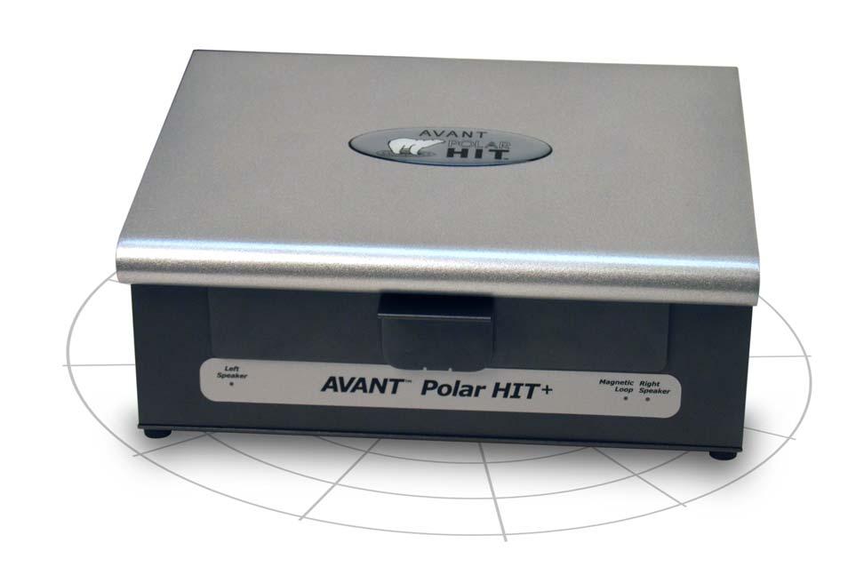
4 Getting to Know Your AVANT Polar HIT The AVANT Polar HIT represents a new era of precision Hearing Instrument Testing for your office. Compact yet rugged, this PC-Based system is USB powered and performs all required ANSI and IEC tests. A unique feature of the Polar HIT is a rotating test pad, which allows you to generate polar plots to verify the performance of directional microphones upon delivery and following repairs. The following section of this manual will familiarize you with the physical features and accessories of the Polar HIT system. Front View Rear View Note the single high-speed USB 2.0 (backward compatible to USB 1.1) connector, which supplies the unit with power and transmits software control and data acquisition. 4


5 Inside the Test Chamber Detail view of the Rotating Test Pad 5


6 Setting up the System Install the Coupler Microphone The Reference Microphone is pre-installed at the factory and should be flush or nearly flush with the floor of the rotating test pad. Carefully install the coupler microphone as shown in the images below. Take care when handling these components, as they are delicate, precision calibrated instruments. Install the Coupler Microphone as shown above. Once the microphones are installed, you must install the Polar HIT Software and Drivers. This procedure is detailed in the next sections of this manual. If you have difficulty with these steps, contact MedRx Technical Support at (888) or


7 Software Installation Do Not Plug in the AVANT POLAR HIT TM USB Cable yet 1. Insert the AVANT HIT TM CD-ROM into the CD drive. Wait until the Setup program starts. 2. On the Setup screen, choose Install Avant HIT. If the Setup program does not start automatically: Open Computer explorer from Windows Start menu. Double Click on the CD Drive icon. This should open the AVANT TM Setup screen shown at the top left. If it does not, Windows will display a list of files on the CD ROM. Double Click Setup.exe 3. Wait for the program to setup the InstallShield Wizard. 7


8 4. This is the Welcome screen Click Next. 5. Read the Software License Agreement. This important document defines the acceptable usage of the Polar HIT. After reading the Agreement, click I accept... Click Next. 6. This screen indicates the location of the program files. Click Next. Note: You can install the Software to a different location, but it is not recommended. 7. Choose desired Locale Click Next. 8


9 8. Ready to Install Program. Click Install. 9. Wait while the InstallShield Wizard installs the AvantHIT program. Click Next. 10. When the installation is complete, click Finish. 9

10 Driver Installation on Windows 7 (see page 13 for Windows XP Driver Installation) Because drivers are loaded to specific USB ports, it is essential that the Polar HIT cable be connected to the same USB port on your computer each time it is used. It is advisable to mark this port with a label to assist with identifying it should the cable need to be disconnected. 1. Connect the USB cable from the AVANT POLAR HIT TM to your computer as shown above. 2. Wait for the system to copy and install default drivers. During this process, you will see the following screen. 3. When this screen appears and all devices are Ready to use, click Close. 4. On the AvantHIT Setup screen, click Install Drivers. 10


11 5. When this screen appears, click Ok. 6. When this window appears and all devices are Ready to use, click Close. 7. If this warning screen appears, click Install this driver software anyway. 8. On Setup Window click Exit 11


 audio device and then choose Set Default.")
12 Next you need to set the Default Windows sound card settings. This will route all non-avant TM Windows sounds to the internal sound card of your computer. These sounds include event notifications such as new and error warnings as well as audio and video playback. 1. Launch the AVANT HIT software. 2. Open the Advanced Options from File menu as shown. 3. Open Audio tab. 4. When the audio properties are configured properly, during driver installation, the Audio Tab will appear like the image on the left. If not, use the pull-down lists to adjust the settings to match the image. 5. Click Audio Properties. In Windows Sound control panel, make sure the MedRx Audio Device is not set as default. If it is default, change this by clicking on your system (non-medrx) audio device and then choose Set Default. NOTE: The internal sound card on your computer will likely not have the same name as this screen shot. Consult your computer s documentation for the name of the internal sound card and set this control accordingly. 12


. 3.")
13 Driver Installation on Windows XP Because drivers are loaded to specific USB ports, it is essential that the Polar HIT cable be connected to the same USB port on your computer each time it is used. It is advisable to mark this port with a label to assist with identifying it should the cable need to be disconnected. 1. Connect the USB cable from the AVANT POLAR HIT TM to your computer as shown above. 2. Wait for the system to copy and install default drivers. During this process, you will see the following prompts in your system tray (lower right corner of the screen). 3. After the Window drivers have been installed, insert the Avant HIT installation CD into the CD Drive. 4. When this screen appears, click Install Drivers. 13


14 5. When this screen appears, click OK. 6. When the driver signature check screen appears, click Continue Anyway. 7. When this window appears, 8. Select No, not at this time 9. Click Next. 10. When this screen appears, 11. Select Install the software automatically (recommended). 12. Click Next. 14

15 13. When this screen appears, 14. Click Finish. Exit the Setup screen when the driver installation is finished. 15


16 Next you need to set the Default Windows sound card settings. This will route all non-avant TM Windows sounds to the internal sound card of your computer. These sounds include event notifications such as new and error warnings as well as audio and video playback. 1. Launch the AVANT HIT software 2. Open the Advanced Options as shown 3. Click on the Audio Tab 4. Click the Audio Properties button 5. Using the pull downs, set the Sound Playback and Sound Recording Default devices to the internal sound card of your computer. 6. NOTE: The internal sound card on your computer will likely not have the same name as this screen shot (SigmaTelAudio). Consult your computer s documentation for the name of your internal sound card and set this control accordingly. 7. When the audio properties are configured properly, the Audio Tab will appear like the image on the left. If not, use the pull-down lists to adjust the settings to match the image. 16


17 Accessories Couplers The system includes the couplers and adapters shown below. These will allow you to perform all ANSI and IEC Hearing Instrument Tests. Also included are two special accessories used only for Polar Plots. Note: There is a flexible O-ring inside both the 2cc Coupler and the Button Receiver Adapter. These must remain in place for the couplers to function properly. Replacement O-rings are available from MedRx. Battery Pills Battery Pills, also known as Battery Simulators, provide power to the hearing instrument during testing. The system includes a complete set of Battery Pills as shown below. 17
18 EMC Precautions The Avant Polar Hearing Instrument Test (HIT) box needs special precautions regarding EMC and needs to be installed according to the following EMC information. List of all cables and maximum lengths of cables, transducers and accessories: Transducer / Accessories USB Cable Battery Simulators (All Versions) Microphones (All Versions) Maximum Cable length 2.9 meters 0.3 meters 0.3 meters Warnings! The use of accessories, transducers and cables other than those specified, with the exception of transducers and cables sold by the manufacturer of the Avant Polar Hearing Instrument Test box as replacement parts for internal components, may result in increased emissions or decreased immunity of the Avant Polar Hearing Instrument Test Box. The Avant Polar Hearing Instrument Test Box should not be used adjacent to or stacked with other equipment. If adjacent or stacked use is necessary, the Avant Polar Hearing Instrument Test box should be observed to verify normal operation in the configuration in which it will be used. The Avant Polar Hearing Instrument Test Box may be interfered with by other equipment, even if that other equipment complies with CISPR emission requirements. The Avant Polar Hearing Instrument Test Box does not have life supporting function Portable and mobile RF communications equipment can affect the Avant Polar Hearing Instrument Test Box. Guidance and manufacturer s declaration electromagnetic emissions The Avant Polar Hearing Instrument Test box is intended for use in electromagnetic environment specific below. The customer or the user of the Avant Polar Hearing Instrument Test box should assure that it is used in such an environment. Emission test Compliance Electromagnetic environment - guidance RF emissions CISPR 11 Group 1 The Avant Polar Hearing Instrument Test box uses RF energy only for its internal function. Therefore, its RF emissions are very low and are not likely to cause any interference in nearby electronic equipment. RF emissions CISPR 11 Harmonic emissions IEC Voltage fluctuations / flicker emissions IEC Class B Non applicable Non applicable The Avant Polar Hearing Instrument Test box is suitable for use in all establishments, including domestic establishments and those directly connected to the public low - voltage power supply network that supplies buildings used for domestic purposes. 18
19 Guidance and manufacturer s declaration electromagnetic immunity The Avant Polar Hearing Instrument Test box is intended for use in electromagnetic environment specific below. The customer or the user of the Avant Polar Hearing Instrument Test box should assure that it is used in such an environment. Immunity test Electrostatic discharge (ESD) IEC IEC test level +/- 6 kv contact +/- 8 kv air Compliance level +/- 6 kv contact +/- 8 kv air Electromagnetic environment - guidance Floors should be wood, concrete or ceramic tile. If floors are covered with synthetic material, the relative humidity should be at least 30%. Electrical fast transient / burst IEC /- 2 kv for power supply lines +/- 1 kv for input / output lines +/- 2 kv for power supply lines +/- 1 kv for input / output lines Mains power quality should be that of a typical commercial or hospital environment. Power frequency (50/60 Hz) Magnetic field IEC A/m 3 A/m Power frequency magnetic fields should be at levels characteristic of a typical location in a typical commercial or hospital environment. Guidance and manufacturer s declaration electromagnetic immunity The Avant Polar Hearing Instrument Test box is intended for use in electromagnetic environment specific below. The customer or the user of the Avant Polar Hearing Instrument Test box should assure that it is used in such an environment. Immunity test IEC test level Compliance level Electromagnetic environment - guidance Portable and mobile RF communications equipment should be used no closer to any part of the Avant Polar Hearing Instrument Test box, including cables, than the recommended separation distance calculated from the equation applicable to the frequency of the transmitter. Recommended separation distance: Conducted RF IEC V eff 3 V eff d = 1,17 P Radiated RF IEC V/m 80 MHz to 2,5 GHz 3 V/m d = 1,17 P 80 to 800 MHz d = 2,33 P 800 MHz to 2,5 GHz Where P is the maximum output power rating of the transmitter in watts (W) according to the transmitter manufacturer and d is the recommended separation distance in meters (m). Field strengths from fixed RF transmitters, as determined by an electromagnetic site survey a, should be less than the compliance level in each frequency range b. Interference may occur in the vicinity of equipment marked with the following symbol: 19
20 NOTE 1 At 80 MHz and 800 MHz, the higher frequency ranges applies. NOTE 2 These guidelines may not apply in all situations. Electromagnetic propagation is affected by absorption and reflection from structures, objects and people. a b Field strengths from fixed transmitters, such as base stations for radio (cellular/cordless) telephones and land mobile radios, amateur radio, AM and FM radio broadcast and TV broadcast cannot be predicted theoretically with accuracy. To assess the electromagnetic environment due to fixed RF transmitters, an electromagnetic site survey should be considered. If the measured field strength in the location in which the Avant Polar Hearing Instrument Test box is used exceeds the applicable RF compliance level above, the Avant Polar Hearing Instrument Test box should be observed to verify normal operation. If abnormal performance is observed, additional measures may be necessary, such as reorienting or relocating the Avant Polar Hearing Instrument Test box. Over the frequency range 150 khz to 80 MHz, field strengths should be less than 3 V/m. Recommended separation distances between Portable and mobile RF communications equipment and the Avant Polar Hearing Instrument Test box The Avant Polar Hearing Instrument Test box is intended to use in an electromagnetic environment in which radiated RF disturbances are controlled. The customer or the user of the Avant Polar Hearing Instrument Test box can help prevent electromagnetic interference by maintaining a minimum distance between portable and mobile RF communications equipment (transmitters) and the Avant Polar Hearing Instrument Test box as recommended below, according to the maximum output power of the communications equipment. Rated maximum output power of transmitter W Separation distance according to frequency of transmitter meters 150 khz to 80 MHz d = 1,17 P 80 MHz to 800 MHz d = 1,17 P 800 MHz to 2,5 GHz d = 2,33 0,01 0,12 0,12 0,233 0,1 0,37 0,37 0,74 1 1,17 1,17 2, ,7 3,7 7, ,7 11,7 23,3 For transmitters rated at a maximum output power not listed above, the recommended separation distance d in meters (m) can be estimated using the equation applicable to the frequency of the transmitter, where P is the maximum output power rating of the transmitter in watts (W) according to the transmitter manufacturer. NOTE 1 At 80 MHz and 800 MHz the separation distance for the higher frequency range applies. NOTE 2 These guidelines may not apply in all situations. Electromagnetic propagation is affected by absorption and reflection from structures, objects and people. P 20
21 Congratulations Your Avant Polar HIT system is now set up and ready to test hearing instruments. Please consult the Avant Polar HIT User Manual and the Interactive Help within the software for instructions and procedures. Limited Warranty MedRx, Inc warrants the AVANT POLAR HIT TM System to be free from defects in material and workmanship for one year from the time of purchase. If this system fails to perform as specified during this period, the purchaser is responsible for calling MedRx at (888) The company's representative will advise the owner to either return specific components or the entire system to: MedRx, Inc Starkey Road #105 Largo, FL MedRx will repair or replace any defective parts, fully test the system and/or components and ship the system promptly back to the owner. There is no cost for the repair or return shipping, provided the system is one year old or less and has not been misused, abused or damaged. Such damage includes, but is not limited to, dropping, exposure to excessive heat greater than 100ºF and water/liquid damage. Warranty does not include cables or connectors. Repair or replacement of the system as provided under this warranty is the sole and exclusive remedy of the purchaser. MedRx shall not be liable for any consequential or incidental damages, or for breach of any express or implied warranty. Except to the extent of applicable law, any implied warranty, merchantability or fitness of this product is limited to the duration of this warranty. MedRx will, at its discretion, service and repair out of warranty components at the purchaser's request, charging for parts and labor as necessary. The limited warranty is deemed void if software or hardware is installed on the AVANT POLAR HIT TM which is not pre-approved by MedRx, Inc. Approved software includes NOAH and HIMSA approved hearing aid manufacture programming modules for fitting hearing aids. MedRx, Inc is not responsible for problems resulting from installation of unapproved software or hardware. In the event of unapproved software or hardware installed on the system causing a conflict with the AVANT POLAR HIT TM functions, MedRx will service the problem for a fee to be determined at the time of service. 21
#
 INSTALLATION MANUAL 2 Contents Getting To Know Your AVANT POLAR HIT TM... 4 Setting up the System... 6 Software Installation... 7 Driver Installation Windows 7... 10 Driver Installation Windows XP... 13
INSTALLATION MANUAL AVANT HIT+ Hearing Instrument Test Chamber.
 INSTALLATION MANUAL AVANT Hearing Instrument Test Chamber HIT+ www.medrx-int.com Contents Getting To Know Your AVANT HIT+. 3 Computer Requirements 4 Setup System. 5 Software Installation.. 6 Sound Card
#0086.
 INSTALLATION MANUAL Contents Getting to Know Your AVANT REM Speech+... 3 Software Installation... 4 Driver Installation Windows 7... 7 EMC Precautions... 11 Safety... 15 Limited Warranty... 18 #0086 www.medrx-usa.com
D C 01/2019 3
 D-0117968-C 01/2019 3 4 D-0117968-C 01/2019 Screw Driver Screw Driver Unplug both the Red & Blue connectors. (see above) Place a small flat head screw driver on the small orange tabs and push down while
BIODEX MULTI- JOINT SYSTEM
 BIODEX MULTI- JOINT SYSTEM CONFORMANCE TO STANDARDS 850-000, 840-000, 852-000 FN: 18-139 5/18 Contact information Manufactured by: Biodex Medical Systems, Inc. 20 Ramsey Road, Shirley, New York, 11967-4704
Guidance and Declaration - Electromagnetic Compatibility (EMC) for the Delfi PTS ii Portable Tourniquet System
 for the Delfi PTS ii Portable Tourniquet System") Guidance and Declaration - Electromagnetic Compatibility (EMC) for the Delfi TS ii ortable Tourniquet System Guidance and manufacturer s declaration electromagnetic emissions The TS ii ortable Tourniquet
Guidance and Declaration - Electromagnetic Compatibility (EMC) for the Delfi TS ii ortable Tourniquet System Guidance and manufacturer s declaration electromagnetic emissions The TS ii ortable Tourniquet
Electromagnetic compatibility Guidance and manufacturer s declaration DIN EN :2007 (IEC :2007)
") Compressor set Equipment Under Test (EUT) Type 028 Type 047 Type 052 Type 085 Electromagnetic compatibility Guidance and manufacturer s declaration DIN EN 60601-1-2:2007 (IEC 60601-1-2:2007) 2017 PARI
Compressor set Equipment Under Test (EUT) Type 028 Type 047 Type 052 Type 085 Electromagnetic compatibility Guidance and manufacturer s declaration DIN EN 60601-1-2:2007 (IEC 60601-1-2:2007) 2017 PARI
Powered Traction Unit OPERATION MANUAL
 Powered Traction Unit OPERATION MANUAL CONTENTS Symbols Safety precautions Symbol for CAUTION Symbol for CONSULT INSTRUCTIONS FOR USE Symbol for SERIAL NUMBER Symbol for CATALOGUE NUMBER Symbol for AUTHORISED
HeRO duet
 HeRO duet CUSTOMER SERVICE TABLE OF CONTENTS TABLE OF CONTENTS OVERVIEW OVERVIEW OVERVIEW OVERVIEW USING HeRO duet USING HeRO duet USING HeRO duet Current HeRO Score HeRO USING HeRO duet USING HeRO duet
Biological Safety. Electromagnetic Compatibility (EMC) Observe the following precautions related to biological safety.
 Observe the following precautions related to biological safety.") Biological Safety Observe the following precautions related to biological safety. WARNING: Non-medical (commercial) grade peripheral monitors have not been verified or validated by SonoSite as being suitable
Biological Safety Observe the following precautions related to biological safety. WARNING: Non-medical (commercial) grade peripheral monitors have not been verified or validated by SonoSite as being suitable
General Safety/EMC and Electrical Information for i-limb ultra and i-limb digits
 1. General Safety 1.1 The i-limb ultra and i-limb digits devices are electrical devices, which under certain circumstances could present an electrical shock hazard to the user. Please read the accompanying
Technical Specifications Micromedical VisualEyes 505 by Interacoustics
 VisualEyes 505 - Technical Specifications Page 0 Technical Specifications Micromedical VisualEyes 505 by Interacoustics D-0115523-B 2018/02 VisualEyes 505 - Technical Specifications Page 1 Included and
English
 English Specifications Type Power Source Vibration Frequency Maximum Output Power Consumption Water Pressure Lighting NE134 AC120V 50/60Hz AC230V 50/60Hz 28~32kHz 8W Max. 42VA 0.1~0.5MPa (1~5kgf/cm
VN415/VO425 Specifications
 VN415/VO425 Specifications Item No. 8105231-1 01/2014 Contents VN415 Specifications... 1 1.1 Technical Standards:...1 1.2 System Requirements:...1 1.3 Included and Optional Parts...2 VO425 Specifications...
User Instruction Computer Assisted Local Analgesia. 337 Marion, Le Gardeur QC, Canada, J5Z 4W8
 User Instruction Computer Assisted Local Analgesia 1-800-667-9622 337 Marion, Le Gardeur QC, Canada, J5Z 4W8 USER INSTRUCTION Congratulations on your new CALAJECT! Please read these instructions thoroughly
INSTALLATION MANUAL
 INSTALLATION MANUAL www.medrx-usa.com Contents Getting to Know Your AVANT ARC... 3 Transducers & Accessories... 5 Software Installation... 6 Loading Calibration Files... 14 EMC Precautions... 15 Safety...
INSTALLATION MANUAL
 INSTALLATION MANUAL www.medrx-usa.com Contents Getting to Know Your AVANT ARC... 3 Transducers & Accessories... 5 Software Installation... 6 Loading Calibration Files... 14 EMC Precautions... 15 Safety...
OtoRead - Technical Specifications Page 0. Technical Specifications. OtoRead D A 2017/06
 OtoRead - Technical Specifications Page 0 Technical Specifications OtoRead D-0116698-A 2017/06 OtoRead - Technical Specifications Page 1 OtoRead TM Configuration Overview The OtoReadTM is available in
PHYSIOFLOW Q-LINK TM
 PHYSIOFLOW Q-LINK TM Service Manual Thursday, 20 October 2016 First placing on the market : 18 January 2012 User Manual PhysioFlow Q-Link 1/17 Table of contents 1. General Information... 3 About this manual...
#
 Contents Getting to Know Your AVANT ARC... 3 Computer Requirements... 4 Transducers & Accessories... 6 Probe Mic Hanger Installation... 7 Software Installation... 9 Connecting the Device... 15 Loading
(c) Medisave UK. Notice. Edition 1. i-pad Operator s Manual
 Medisave UK. Notice. Edition 1. i-pad Operator s Manual") Edition 1 Notice i-pad Operator s Manual CU Medical Systems, Inc. reserves the right to make changes on the device specifications contained in this manual at any time without prior notice or obligation
Edition 1 Notice i-pad Operator s Manual CU Medical Systems, Inc. reserves the right to make changes on the device specifications contained in this manual at any time without prior notice or obligation
Not for print. Microphone Test Device with SONNET MTD Adapter. User Manual. Cochlear Implants NOT FOR PRINT
 Cochlear Implants Microphone Test Device with SONNET MTD Adapter User Manual AW32690_1.0 (English) Table of contents 1. Table of contents 2. INTRODUCTION 3 Product description 3 3. INTENDED USE INDICATIONS
Nursing Beds with Dewert drive system
 Nursing Beds with Dewert drive system GB Casa Med Classic 4 / Classic (FS) Casa Med Ultra / Ultra (FS) Casa Med Classic Low Casa Med Classic (FS) 4 / Classic / Casa FS Med / Casa Classic Med Low Ultra
USER MANUAL MHS-2500I. Please take time to read these instructions before starting to use the scale. Version /17
 USER MANUAL MHS-2500I Please take time to read these instructions before starting to use the scale Version 1.0 05/17 Contents Introduction 3 Product Specification 3 Safety Instructions 4 Explanation of
INTRODUCTION. 4 SAFETY INSTRUCTIONS. 5 ABOUT THIS DEVICE. 6 FIRST OPERATION. 7 THE DISPLAY. 8 ATTACHING THE WRIST SLEEVE. 9 CORRECT MEASUREMENT.
 Table of contents INTRODUCTION.............................. 4 SAFETY INSTRUCTIONS........................ 5 ABOUT THIS DEVICE.......................... 6 FIRST OPERATION............................ 7
TH008F Multi-function Infrared Forehead Thermometer
 TH008F Multi-function Infrared Forehead Thermometer Specifications Functions Temperature measurement range: Forehead mode: 34~42.2 C (93.2~108 F), Surface mode: -22~80 C (-7.6~176 F) Operating temperature
Rolyan Splint Pan OPERATION MANUAL. Item # Small Item # Large
 Rolyan Splint Pan OPERATION MANUAL Item #081544816 - Small Item #081544808 Large PLEASE READ THIS ENTIRE MANUAL BEFORE OPERATING YOUR NEW SPLINT PAN. Failure to follow these instructions could result in
DENTAL X-RAY OPERATOR'S INSTRUCTIONS. (for USA) Wall Mount Type...WK
 Wall Mount Type...WK") M 505 DENTAL X-RAY OPERATOR'S INSTRUCTIONS (for USA) Wall Mount Type...WK WARNING This X-ray equipment may be dangerous to patient and operator unless safe exposure factors, operating instructions and
M 505 DENTAL X-RAY OPERATOR'S INSTRUCTIONS (for USA) Wall Mount Type...WK WARNING This X-ray equipment may be dangerous to patient and operator unless safe exposure factors, operating instructions and
USER MANUAL M-200. Please take time to read these instructions before starting to use the scale. Version /06
 USER MANUAL M-200 Please take time to read these instructions before starting to use the scale Version 1.0 07/06 Contents Introduction 3 Product Specification 3 Safety Instructions 4 Explanation of Graphic
Technical Data. Electrocardiograph ECG-1250K TD.ECG1250_L. This technical data may be revised or replaced by Nihon Kohden at any time without notice.
 Technical Data Electrocardiograph ECG-1250K This technical data may be revised or replaced by Nihon Kohden at any time without notice. TD.ECG1250_L Specifications ECG input Input impedance: 20 MΩ Electrode
M-400 M-410 M-420 M-430
 USER MANUAL M-400 M-410 M-420 M-430 Please take time to read these instructions before starting to use the scale Version 1.1 10/17 Contents Introduction 3 Product Specification 3 Safety Instructions 4
Operating Manual Infrared thermometer
 Operating Manual Infrared thermometer Model:IT-121 Professional Fast Accurate 1 CONTENTS 1 I n t r o d u c t i o n................ 3 1.1Product intended use 3 2 Basic principle 3 3 Pr o d u c t f e a t
The following symbol indicates that the device is MR-unsafe:
 The following symbol indicates that the device is MR-unsafe: MR Unsafe Do not use this equipment In the MRI scan room Patient must follow the doctor s instructions and should not perform a self-assessment
OPERATOR S MANUAL AN APPLIED DIGITAL COMPANY
 OPERATOR S MANUAL AN APPLIED DIGITAL COMPANY Contents: VeriChip H2 Reader Assembly Part Number 600-000515-000 (includes all of the following): USER INSTRUCTIONS Description Part Number Description The
Ceiling Model Ceiling Model for LEDview Plus and Heliodent Plus. Installation Requirements. New as of: English
 New as of: 03.2017 Ceiling Model Ceiling Model for LEDview Plus and Heliodent Plus Installation Requirements English Installation Requirements Ceiling Version = Dentsply Sirona Installation Requirements
: 0089 GTIN
 GTIN: 00894912002050 PRECAUTIONS PROBE Non-invasive probes are for transcutaneous use only Probe transducer tips are thin and delicate. Be careful not to drop or hit the probe tip. After use, protect the
USER S MANUAL Volk Pictor Plus Fluorescein Angiography (FA) Module For Use with: Volk Pictor Plus
 Module For Use with: Volk Pictor Plus") USER S MANUAL Volk Pictor Plus Fluorescein Angiography (FA) Module For Use with: Volk Pictor Plus IM-080 Rev. A Page 1 of 16 THIS SALES PACKAGE INCLUDES: Model: Fluorescein Angiography (VP2FA) IM-080 Description:
USER S MANUAL Volk Pictor Plus Fluorescein Angiography (FA) Module For Use with: Volk Pictor Plus IM-080 Rev. A Page 1 of 16 THIS SALES PACKAGE INCLUDES: Model: Fluorescein Angiography (VP2FA) IM-080 Description:
The following languages can be found on our website: French. German. Spanish. Italian. Swedish. Portuguese. Russian. Dutch.
 Manufactured By: 5580 S. Nogales Hwy. Tucson, Az 85706 USA Telephone: 800-975-7987 Fax: 520-294-6061 www.westmedinc.com PN 74586, Rev. 10 MT Promedt Consulting GmbH Altenhofstr. 80 66386 St. Ingbert, Germany
14 CHANNEL FAMILY RADIO SYSTEM MODEL # FR142
 14 CHANNEL FAMILY RADIO SYSTEM MODEL # FR142 2001 Audiovox Electronics Corp., Hauppauge, NY 11788 Printed in China 128-6020 052FR142104 BEFORE OPERATING THIS PRODUCT PLEASE READ THESE INSTRUCTIONS COMPLETELY
Using the USB Output Port to Charge a Device
 Table of Contents ----------------------------------- 2 Features ----------------------------------------------- 3 Controls and Functions ---------------------------------- 4 ER210 Power Sources -----------------------------------
ER200 COMPACT EMERGENCY CRANK DIGITAL WEATHER ALERT RADIO OWNER S MANUAL
 ER200 COMPACT EMERGENCY CRANK DIGITAL WEATHER ALERT RADIO OWNER S MANUAL Table of Contents -------------------------------------- 2 Features ----------------------------------------------- 3 Controls and
Acu-Park TM. user s guide Directed Electronics, Inc. Vista, CA N9100T 09-04
 Acu-Park TM user s guide 2004 Directed Electronics, Inc. Vista, CA N9100T 09-04 limited one year warranty Directed Electronics, Inc. (hereinafter "Directed") promises to the original purchaser that this
SPAC265-8W. AC-DC power supply module. Features. Description. Applications
 AC-DC power supply module Datasheet production data Features Open frame switch mode power supply European input voltage range Single output 5 V, 8 W peak power, 4 W continuous operating mode EMC compliance
`bob`=p=^åèìáëáíáçå=råáí=bma
 `bob`=p=^åèìáëáíáçå=råáí=bma qéåüåáå~ä=a~í~= båöäáëü The new CEREC 3 generation for the computer-aided manufacture of ceramic restorations. CAD system for making high-precision optical impressions in the
ibed Locator Model 5212
 ibed Locator Model 5212 Connected Hospital Instructions for Use and Installation For Parts or Technical Assistance: USA: 1-800-327-0770 2011/03 5212-009-101 REV C www.stryker.com Table of Contents Symbols
SAVI SCOUT Surgical Guidance System. Console Operation Manual
 SAVI SCOUT Surgical Guidance System Console Operation Manual 2 Copyrights and Trademarks 2016 Cianna Medical, Inc. All rights reserved. Patents pending. Cianna Medical and SAVI are registered trademarks
TRITON - USB Audio Interface
 TRITON - USB Audio Interface User Manual Version 2 July 2018 Package Contents 1. USB audio interface Standard version (grey) or IEPE version (black) 2. CA05 USB-A/C cable 3. Quick Guide 4. LP03 leather
USB Microphone. Marshall Electronics
 USB Microphone Marshall Electronics Warranty Marshall microphones are guaranteed against defects in material and workmanship for one year from date of purchase. Should you encounter any problem with this
BROADBAND LINEAR AMPLIFIER Model P150
 ELECTRONICS AB BROADBAND LINEAR AMPLIFIER Model P150 HIGH VOLTAGE GAIN HIGH CURRENT +150V 20x 1A HIGH POWER SMALL SIGNAL SLEW RATE BANDWIDTH BANDWIDTH 30 V/µs DC to ca 60 khz DC to >200 khz FLC Electronics
Manual and User Guide
 Manual and User Guide TV Talker FM System Model WFM 260 Model WFM 270 Transmitter Model WFM TX260 Receiver Model WFM RX260 Receiver Model WFM RX270 MAN 151H 2011 Williams Sound, LLC Contents Page System
NEO CAR AUDIO. Neo AUXiN AUX INPUT INTERFACE. Instruction Manual
 NEO CAR AUDIO Neo AUXiN AUX INPUT INTERFACE Instruction Manual IMPORTANT NOTE Neo AUXiN Dip switch positions MUST be set BEFORE any other step is taken. Otherwise, the kit will not operate properly. See
FM RADIO TRANSMITTER
 FM RADIO TRANSMITTER Instruction Manual i702 Please read this manual carefully before operating and save it for future reference. Questions? Please visit http://www.i-luv.com CONTENTS INTRODUCTION General
`bob`=p=^åèìáëáíáçå=råáí
 `bob`=p=^åèìáëáíáçå=råáí qéåüåáå~ä=a~í~= båöäáëü The new CEREC 3 generation for the computer-aided manufacture of ceramic restorations. CAD system for making high-precision optical impressions in the mouth.
MODEL 3810/2 Line Impedance Stabilization Network
 EMC TEST SYSTEMS FEBRUARY 1996 REV C PN 399197 MODEL 3810/2 Line Impedance Stabilization Network OPERATION MANUAL USA P.O. Box 80589 Austin, Texas 78708-0589 2205 Kramer Lane, Austin, Texas 78758-4047
Draft. User s Manual. Transmitter Model EX1150
 User s Manual Merlin @home Transmitter Model EX1150 CAUTION Federal (USA) law restricts this device to sale by or on the order of a physician. 2008 St. Jude Medical Cardiac Rhythm Management Division.
Rotating Anode X-Ray Tube Housing Assembly. General Data
 Technical Data TD ROTANODE E7252X E7252FX E7252GX 0197 Rotating Anode X-Ray Tube Housing Assembly High speed rotating anode X-ray tube housing assembly for high energy radiographic and cine-fluoroscopic
SAS-563B Active Loop Antenna Operation Manual
 SAS-563B Active Loop Antenna Operation Manual 1 TABLE OF CONTENTS INTRODUCTION 3 SPECIFICATIONS 5 OPERATING INSTRUCTIONS 7 CALCULATIONS 11 ANTENNA FORMULAS 12 MAINTENANCE 13 WARRANTY 14 2 INTRODUCTION
Congratulations on Purchasing the MedRx Deluxe Video Otoscope
 Congratulations on Purchasing the MedRx Deluxe Video Otoscope The MedRx Video Otoscope System Includes: MedRx Patented OtoScope Probe MedRx High Resolution Camera High Resolution Sony Color Video Monitor
GTIN:
 GTIN: 00894912002920 TABLE OF CONTENTS Introduction...1 Features...1 Indications for Use...1 Contraindications...1 Warnings & Precautions...2 Controls...3 Operation...4 Recharging the Battery...5 Replacing
H2 Check Operating Manual
 H2 Check Operating Manual Federal (USA) law restricts this device to sale by or on the order of a physician or licensed practitioner. Micro Direct, Inc. 803 Webster Street Lewiston, ME 04240 1-800-588-3381
GT-1050A 2 GHz to 50 GHz Microwave Power Amplifier
 Established 1981 Advanced Test Equipment Rentals www.atecorp.com 800-404-ATEC (2832) Giga-tronics GT-1050A Microwave Power Amplifier GT-1050A 2 GHz to 50 GHz Microwave Power Amplifier Operation Manual
DL102 Counter Loop Amplifier
 DL102 Counter Loop Amplifier USER MANUAL MAN 234A Contents Overview...3 System Includes...3 Maintenance and Recycling Instructions...3 Safety Information...4 Quick Setup...5 Setup...6 Loop Amplifier...6
WRIST BLOOD PRESSURE MONITOR
 WRIST BLOOD PRESSURE MONITOR Instruction Manual MODEL: ABP801 www.accumed.com TABLE OF CONTENTS INTRODUCTION... 1 NOTES ON SAFETY... 1 ABOUT BLOOD PRESSURE... 3 PRECAUTIONS BEFORE US... 4 FEATURES OF THE
HD STETH TM Quick Start User Guide
 Thank you and for choosing the futuristic HD Steth TM manufactured by HD Medical Inc. USA Indications for Use (IFU) HD Steth is an electronic stethoscope meant to assist a qualified clinician to capture,
CardioMessenger II-S Transmitter for BIOTRONIK Home Monitoring. Technical Manual
 CardioMessenger II-S Transmitter for BIOTRONIK Home Monitoring 362454_D_GA_CM_II-S_US.indd 1 Technical Manual 17.04.08 16:28:16 by BIOTRONIK GmbH & Co. KG All rights reserved. Specifications subject to
MXL USB.006.
 MXL USB.006 www.mxlmics.com Congratulations on your purchase of the MXL USB.006 which uses a large 32mm gold diaphragm capsule for added warmth. MXL microphones are the result of world-class engineering
MP-1 Microphone Preamplifier User Guide and Technical Information
 SOUND DEVICES MP-1 Microphone Preamplifier Voice 608.524.0625 Fax 608 524.0655 www.sounddevices.com General Description The MP-1 from Sound Devices is a portable, battery-powered microphone preamplifier
DIGITAL AUDIO AMPLIFIER WITH BLUETOOTH. Model: DAA User Manual
 DIGITAL AUDIO AMPLIFIER WITH BLUETOOTH Model: DAA User Manual IMPORTANT INSTRUCTIONS When using electrical products, basic precautions should always be followed, including the following: WARNING: Risk
RFTX-1 Installation Manual
 RFTX-1 Installation Manual complete control Universal Remote Control RFTX-1 Installation Manual 2009-2014 Universal Remote Control, Inc. The information in this Owner s Manual is copyright protected. No
TEMPO USB MICROPHONE
 TEMPO USB MICROPHONE Congratulations on your purchase of the MXL Tempo USB microphone. MXL microphones are the result of worldclass engineering and manufacturing capabilities. They are designed to provide
EMC Test Report. Report Number: M030826
 Page 1 of 36 EMC Technologies Pty Ltd ABN 82 057 105 549 57 Assembly Drive Tullamarine Victoria Australia 3043 Ph: + 613 9335 3333 Fax: + 613 9338 9260 email: melb@emctech.com.au EMC Test Report Report
UNCONTROLLED WHEN PRINTED
 TECHNICAL MANUAL ULTRASONIC TEST SET MODEL TS500 MAY 22, 2017 REV A DUKANE SEACOM, INC. SARASOTA, FLORIDA 34243 PHONE: 941-741-3200 FAX: 941-739-3201 DOCUMENT NO. 03-TM-0082 DUKANE SEACOM, INC. INTERNET:
ENG en. Operating instructions. Iris Magneton MF Wellness therapy
 ENG en Operating instructions Iris Magneton MF Wellness therapy Edition 09 / 2012 These operating instructions constitute an accessory of the device. They must therefore be kept in a suitable place near
Transmitter. User Manual. Firmware version 1.0 and greater
 ProRF SPC Transmitter User Manual Firmware version 1.0 and greater FCC NOTICE This equipment has been tested and found to comply with the limits for a class B digital device, pursuant to part 15 of the
L NKTEMP. Non-contact. Infrared Thermometer. User Manual LMP001
 L NKTEMP Non-contact Infrared Thermometer User Manual LMP001 TABLE OF CONTENTS Product Description Intended Use Product Features Safety Precautions Using the Thermometer Taking a Measurement Temperature
HX-3. Headphone Distribution Amplifier User Guide and Technical Information
 HX-3 Headphone Distribution Amplifier User Guide and Technical Information Sound Devices, LLC 300 Wengel Drive Reedsburg, WI USA +1 (608) 524-0625 fax: +1 (608) 524-0655 Toll-Free: (800) 505-0625 www.sounddevices.com
User s Guide ASSISTIVE LISTENING SYSTEMS
 User s Guide ASSISTIVE LISTENING SYSTEMS 2 Digital-1 User s Guide Contents How to use Digital-1...3 Tuning...6 Frequency Chart...8 Correcting Interference...9 Recharging...10 Specifications...12 Notice...13
Veterinary Digital X-Ray System Quick Start Guide
 1 Veterinary Digital X-Ray System Quick Start Guide 2 SOPIX² X-Ray Sensors Quick Start Guide ***PERFORM THIS STEP BEFORE PLUGGING IN THE SENSOR*** Step 1 Load the CD: If you have already plugged in the
SPM-50 RF Spectrum Power Meter PC Software User Manual
 SPM-50 RF Spectrum Power Meter PC Software User Manual Shineway Technologies, Inc. Notices Copyright 2014, ShinewayTech, All rights reserved. No part of this manual may be reproduced in any form or by
SAS-562B Active Loop Antenna Operation Manual
 SAS-562B Active Loop Antenna Operation Manual 1 TABLE OF CONTENTS INTRODUCTION 3 SPECIFICATIONS 5 OPERATING INSTRUCTIONS 7 CALCULATIONS 11 ANTENNA FORMULAS 12 MAINTENANCE 13 WARRANTY 14 2 INTRODUCTION
Model Microphone Preamplifier Power Supply Manual
 Model 2221 Microphone Preamplifier Power Supply Manual Larson Davis Model 2221 Microphone Preamplifier Power Supply Manual I2221.01 Rev H Copyright Copyright 2009-2015 by PCB Piezotronics, Inc. This manual
KRAMER ELECTRONICS LTD. USER MANUAL MODEL: 912 Power Amplifier. P/N: Rev 2
 KRAMER ELECTRONICS LTD. USER MANUAL MODEL: 912 Power Amplifier P/N: 2900-000684 Rev 2 Contents 1 Introduction 1 2 Getting Started 2 2.1 Achieving the Best Performance 2 3 Overview 3 3.1 Defining the 912
CURRENT SENSING 12VOLT TRIGGER CS12V
 I N S T A L L A T I O N G U I D E CURRENT SENSING 12VOLT TRIGGER CS12V CONGRATULATIONS! Thank you for choosing the CS12V from Niles. With proper installation and operation, you should enjoy years of trouble-free
JMAA-3600HR16-UL. Installation and Operation Instructions. Performance Series 360w RMS 4-Channel Amplifier Kit For Harley RoadGlide Ultra
 Performance Series 360w RMS 4-Channel Amplifier Kit For 2016-2018 Harley RoadGlide Ultra # JMAA-3600HR16-UL 2017 J&M Corporation. All rights reserved. 9/17 Installation and Operation Instructions Product
PTT- Z or PTT-U PUSH-TO-TALK Specification
 Federal Communication Commission Interference Statement This equipment has been tested and found to comply with the limits for a Class B digital device, pursuant to Part 15 of the FCC Rules. These limits
2620 Modular Measurement and Control System
 European Union (EU) Council Directive 89/336/EEC Electromagnetic Compatibility (EMC) Test Report 2620 Modular Measurement and Control System Sensoray March 31, 2006 April 4, 2006 Tests Conducted by: ElectroMagnetic
Multi-Control Panel for built-in system. Multi Pad for NLX / imd OPERATION MANUAL OM-E0538E 001
 Multi-Control Panel for built-in system Multi Pad for NLX / imd OPERATION MANUAL OM-E0538E 001 Thank you for purchasing Multi Pad. Read this Operation Manual carefully before use for operation instructions
CT-2 and CT-3 Channel Taggers OPERATION MANUAL
 CT-2 and CT-3 Channel Taggers OPERATION MANUAL Trilithic Company Profile Trilithic is a privately held manufacturer founded in 1986 as an engineering and assembly company that built and designed customer-directed
23070 / Digital Camera Owner s Manual
 23070 / 23072 Digital Camera Owner s Manual 2007 Sakar International, Inc. All rights reserved. 2007 Crayola Windows and the Windows logo are registered trademarks of Microsoft Corporation. All other trademarks
TDS-535 Tuned Dipole Set Operation Manual
 TDS-535 Tuned Dipole Set Operation Manual 1 TABLE OF CONTENTS INTRODUCTION Antenna Set Contents...3 Intended Purposes...4 Range of Environmental Conditions...5 GENERAL INSTRUCTIONS General Description...5
900MHz Digital Hybrid Wireless Outdoor Speakers
 4015004 900MHz Digital Hybrid Wireless Outdoor Speakers User s Manual This 900 MHz digital hybrid wireless speaker system uses the latest wireless technology that enables you to enjoy music and TV sound
IS7705. Installation & Operation Manual AUDIO INTEGRATION KIT. TranzIt LINK
 GET CONNECTED Installation & Operation Manual AUDIO INTEGRATION KIT IS7705 Note to Readers, The information contained within the following documentation is subject to change without notice. Features discussed
IEC Second Edition
 Electromagnetic Compatibility of Medical Electrical Equipment Second Edition Prepared by Mr. James Conrad Presented by Dr. William A. Radasky 1 Second Edition Updates first edition on standards developed
USB.007 Studio Quality USB Stereo Condenser Mic. User Manual
 USB.007 Studio Quality USB Stereo Condenser Mic User Manual Congratulations on your purchase of the MXL USB.007 which uses two gold diaphragm capsules in an X/Y pattern for stereo recording. MXL microphones
Performance Series 360w Amplifier Kit For Harley RoadGlide with Lower/Rear Speakers JMAA-3600HR15-RC
 Performance Series 360w Amplifier Kit For 2015-2018 Harley RoadGlide with Lower/Rear s # JMAA-3600HR15-RC 2017 J&M Corporation. All rights reserved. 9/17 Installation and Operation Instructions Product
Operating Guide SMH 1525DT SMU 4525KT Technology Drive West Melbourne, FL RELM Wireless Corporation. All Rights Reserved CC OG 23
 W I R E L E S S C O R P O R AT I O N Operating Guide 7100 Technology Drive West Melbourne, FL 32904 2000 RELM Wireless Corporation. All Rights Reserved CC OG 23 ULUD01083ZZ RELM WIRELESS CORP. 7100 Technology
ER200 COMPACT EMERGENCY CRANK DIGITAL WEATHER ALERT RADIO OWNER S MANUAL
 ER200 COMPACT EMERGENCY CRANK DIGITAL WEATHER ALERT RADIO OWNER S MANUAL Table of Contents -------------------------------------- 2 Features ----------------------------------------------- 3 Controls and
Performance Series 360w 4-CH Amplifier Kit For Harley Street Glide with Lower/Rear Speakers JMAA-3600HC14-SG
 Performance Series 360w 4-CH Amplifier Kit For 2014-2018 Harley Street Glide with Lower/Rear s # JMAA-3600HC14-SG 2017 J&M Corporation. All rights reserved. 9/17 Installation and Operation Instructions
The Symbol means that the Vet-Tech (200, 250 or 300HF) system intentionally applies some radioelectric energy for diagnostic or treatment purposes.
 system intentionally applies some radioelectric energy for diagnostic or treatment purposes.") IDENTIFICATION The Vet Tech X-ay unit is available with 3 powers: see the box below Denomination 200HF 250HF 300 HF Usual name Vet Tech 200HF Vet Tech 250HF Vet Tech 300HF Power 12 kw 20 kw 30 kw Milli
IDENTIFICATION The Vet Tech X-ay unit is available with 3 powers: see the box below Denomination 200HF 250HF 300 HF Usual name Vet Tech 200HF Vet Tech 250HF Vet Tech 300HF Power 12 kw 20 kw 30 kw Milli
User s Guide FM Transmitter
 TM 12-634 User s Guide FM Transmitter Please read this user s guide before using your new FM Transmitter. 12-634_en.indd 1 Package contents FM Transmitter USB Cable User s Guide Quick Start IMPORTANT SAFETY