VERIFICATION OF COMPLIANCE
|
|
|
- Jeremy Gallagher
- 6 years ago
- Views:
Transcription
1 VERIFICATION OF COMPLIANCE This Verification of Compliance is hereby issued to the product designated below. Product Model Trade name Applicant Patient Infotainment Terminal/ Computer PIT-1502W; PIT-15XXXXXXXXXXXXXXXX; PIT15XXXXXXXXXXXXXXXX (X = 0 ~ 9 or A ~ Z or blank) ADVANTECH Advantech Co. Ltd. No. 1, Alley 20, Lane 26, Rueiguang Road, Neihu District, Taipei 114, Taiwan, R.O.C. Applicable Standard(s) EN : 2007 EN 55011: 2009, Group 1 Class B IEC : 2008; IEC : A1: A2: 2010; IEC : 2004; IEC : 2005; IEC : 2008; IEC : 2009; IEC : 2004 EN : A1: A2: 2009, Class D EN : 2008 Report No. T120229L03-E1 Test Laboratory Compliance Certification Services Inc. No.81-1, Lane 210, Bade 2nd Rd., Lujhu Township, Taoyuan County 33841, Taiwan, R.O.C. Tel: / Fax: This device has been tested and found to comply with the stated standard(s), which is(are) required by the Council Directive of 93/42/EEC. The test results are indicated in the test report and are applicable only to the tested sample identified in the report. Bill Cheng / Section Manager of Linkou Laboratory Date: April 30, 2012


2 CE EMC UPDATE TEST REPORT for Reference No: T E1 Panel PC MODEL: PIT-1502W; **PIT-15XXXXXXXXXXXXXXXX; **PIT15XXXXXXXXXXXXXXXX (X = 0 ~ 9 or A ~ Z or blank) Test Report Number: T120229L03-E1 Issued for Advantech Co. Ltd. No. 1, Alley 20, Lane 26, Rueiguang Road, Neihu District, Taipei 114, Taiwan, R.O.C. Issued By: Compliance Certification Services Inc. Linkuo Laboratory No.81-1, Lane 210, Bade 2nd Rd., Lujhu Township, Taoyuan County 33841, Taiwan, R.O.C. TEL: FAX: service@ccsrf.com Issued Date: April 30, 2012 Note: This report shall not be reproduced except in full, without the written approval of Compliance Certification Services Inc. This document may be altered or revised by Compliance Certification Services Inc. personnel only, and shall be noted in the revision section of the document. The client should not use it to claim product endorsement by TAF, A2LA, NIST or any government agencies. The test results in the report only apply to the tested sample. Page 1 / 65
3 Revision History Rev. Issue Date Revisions Effect Page Revised By 00 November 9, 2010 Initial Issue ALL Angel Hu 01 April 30, 2012 See the following Note Rev.(01) ALL Jill Shiau Note: Rev. (01): 1. Applicant changes product name (Panel PC to Patient Infotainment Terminal/ Computer) and adds two model numbers, just for marketing purpose only. (Please refer to have ** mark items and on this report) 2. Applicant deletes two model numbers (HIT-P15XXXXXXXXXXXXXXXX, HIT-P152), just for marketing purpose only. (Please refer to have ** mark items and page 4, 5 on this report) 3. Applicant adds keypart (Adapter) and upgrades standard version to re-test. (Please refer to have ** mark items and page 4, 5 on this report) 4. Other information, please refer to the T and this test report. Page 2
4 TABLE OF CONTENTS 1 TEST CERTIFICATION TEST RESULT SUMMARY EUT DESCRIPTION TEST METHODOLOGY DECISION OF FINAL TEST MODE EUT SYSTEM OPERATION SETUP OF EQUIPMENT UNDER TEST DESCRIPTION OF SUPPORT UNITS CONFIGURATION OF SYSTEM UNDER TEST FACILITIES AND ACCREDITATIONS FACILITIES ACCREDITATIONS MEASUREMENT UNCERTAINTY EMISSION TEST CONDUCTED EMISSION MEASUREMENT RADIATED EMISSION MEASUREMENT HARMONICS CURRENT MEASUREMENT VOLTAGE FLUCTUATION AND FLICKS MEASUREMENT IMMUNITY TEST GENERAL DESCRIPTION GENERAL PERFORMANCE CRITERIA DESCRIPTION ELECTROSTATIC DISCHARGE (ESD) RADIATED, RADIO-FREQUENCY, ELECTROMAGNETIC FIELD (RS) ELECTRICAL FAST TRANSIENT (EFT) SURGE IMMUNITY TEST CONDUCTED RADIO FREQUENCY DISTURBANCES (CS) POWER FREQUENCY MAGNETIC FIELD VOLTAGE DIP & VOLTAGE INTERRUPTIONS PHOTOGRAPHS OF THE TEST CONFIGURATION...57 APPENDIX 1: PHOTOGRAPHS OF EUT...65 Page 3
5 1 TEST CERTIFICATION Product: Brand: Model: Applicant: Manufacturer: Panel PC PIT-1502W; **PIT-15XXXXXXXXXXXXXXXX; **PIT15XXXXXXXXXXXXXXXX (X = 0 ~ 9 or A ~ Z or blank) ADVANTECH Advantech Co. Ltd. No. 1, Alley 20, Lane 26, Rueiguang Road, Neihu District, Taipei 114, Taiwan, R.O.C. Advantech Co. Ltd. No. 1, Alley 20, Lane 26, Rueiguang Road, Neihu District, Taipei 114, Taiwan, R.O.C. Tested: March 6 ~ April 23, 2012 Test Voltage: Applicable Standards: 230VAC, 50Hz EN : 2007 EN 55011: 2009, Group 1 Class B IEC : 2008 IEC : A1: A2: 2010 IEC : 2004 IEC : 2005 IEC : 2008 IEC : 2009 IEC : 2004 EN : A1: A2: 2009, Class D EN : 2008 Deviation from Applicable Standard None The above equipment has been tested by Compliance Certification Services Inc., and found compliance with the requirements set forth in the Directive 93/42/EEC concerning medical devices and technical standards mentioned above. The results of testing in this report apply only to the product/system, which was tested. Other similar equipment will not necessarily produce the same results due to production tolerance and measurement uncertainties. Approved by: Reviewed by: Bill Cheng Section Manager Jill Shiau Section Manager Page 4
6 2 TEST RESULT SUMMARY EMISSION Standard Item Result Remarks Conducted (Main Port) PASS Meet Class B limit EN : 2007 Conducted (Telecommunication port) PASS Meet Class B limit Radiated PASS Meet Class B limit EN : A1: A2: 2009, Harmonic current emissions PASS Meet Class D limit EN : 2008 Voltage fluctuations & flicker PASS Meets the requirements IMMUNITY EN 55011: 2009, Group 1 Standard Item Result Remarks IEC : 2008 ESD PASS See Item 8.3 of this report IEC : A1: A2: 2010 RS PASS See Item 8.4 of this report IEC : 2004 EFT PASS See Item 8.5 of this report IEC : 2005 Surge PASS See Item 8.6 of this report IEC : 2008 CS PASS See Item 8.7 of this report IEC : 2009 PFMF PASS See Item 8.8 of this report IEC : 2004 Voltage dips & voltage variations PASS Meets the requirements of Voltage Dips: 1) 100% reduction for 0.5 period 2) 60% reduction for 5 period 3) 30% reduction for 25 period, Voltage Interruptions: 1) 100% reduction for 250 period Note: 1. The statements of test result on the above are decided by the request of test standard only; the measurement uncertainties are not factored into this compliance determination. 2. The information of measurement uncertainty is available upon the customer s request. Page 5
7 3 EUT DESCRIPTION Product Model Brand Applicant Serial Number Panel PC PIT-1502W; **PIT-15XXXXXXXXXXXXXXXX; **PIT15XXXXXXXXXXXXXXXX (X = 0 ~ 9 or A ~ Z or blank) ADVANTECH Advantech Co. Ltd. T Received Date October 25, 2010 EUT Power Rating 19VDC, 3.42A; 19VDC, 3.95A Max (75W max) Power Adapter Manufacturer FSP Model FSP075-DMBB1 Power Adapter Power Rating AC Power Cord Type FSP065-RAB ** SINPRO Model MPU For FSP065-RAB I/P: VAC, 50-60Hz, 1.5A O/P: 19VDC, 3.42A For FSP075-DMBB1 I/P: VAC, 50-60Hz, 1.2A O/P: 19VDC, 3.95A Max (75W max) For **MPU I/P: VAC, 47-63Hz, A O/P: 18VDC, 3.5A Max Unshielded, 1.8m (Detachable) to Power Adapter For FSP065-RAB; **MPU Unshielded, 1.8m (Non-detachable) with a Core DC Power Cable Type For FSP075-DMBB1 Unshielded, 1.8m (Non-detachable) with two Cores CPU Manufacturer Atom Model D GHz Memory Manufacturer Apacer Model DDR2 (1GB) 15.6 LCD Panel Manufacturer AUO Model G156XW01 HDD Manufacturer Seagate Model ST AS (160GB) Inverter Board Manufacturer TDK Model TBD563NR-3 Main Board Manufacturer Advantech Model PCM-8501 I/O Board Manufacturer Advantech Model PCM-759 LAN Card Manufacturer Sound Card Manufacturer On Board On Board Page 6
8 I/O PORT I/O PORT TYPES Q TY TESTED WITH 1. USB Port Earphone Port Microphone Port LAN Port COM Port 1 1 Note: 1. According to customer declaration, the EUT have two types for sale, all specification and layout are identical, except back of appearance. (Please refer external photograph) 2. The mean of X (X= 0~9, A~Z or Blank) on model number, they are identical just for marketing purpose only. 3. Client consigns only one sample to test (model number: PIT-1502W). Therefore, the testing Lab. just guarantees the unit, which has been tested. Page 7
9 4 TEST METHODOLOGY 4.1. DECISION OF FINAL TEST MODE 1. The following test mode(s) were scanned during the preliminary test: Pre-Test Mode Mode Resolution Power Adapter x 768, 60Hz x 768, 60Hz SINPRO / MPU x 600, 60Hz 2. After the preliminary scan, the following test mode was found to produce the highest emission level. Final Test Mode Conducted Mode 1 Emission Emission Radiated Mode 1 Emission Immunity Mode 1 Then, the above highest emission mode of the configuration of the EUT and cable was chosen for all final test items. The test items IEC , IEC & IEC were performed at the minimum and maximum RATED input voltages. The worst case (Input: 230VAC) was precisely noted in the test report only. Please refer to the following test result EUT SYSTEM OPERATION 1 Setup the EUT and simulators as shown on EMI test software was loaded and executed in Windows XP mode. 3 The EMI test program sequentially exercised all I/O s of EUT. 4 A communicated software was loaded and executed to communicate between EUT and remote side. 5 The EUT receives message from remote side, and filling the screen with upper case of H patterns. 6 Repeat 3 to 5. Note: Test program is self-repeating throughout the test. Page 8
10 5 SETUP OF EQUIPMENT UNDER TEST 5.1. DESCRIPTION OF SUPPORT UNITS The EUT has been tested as an independent unit together with other necessary accessories or support units. The following support units or accessories were used to form a representative test configuration during the tests. No. Equipment Model No. Serial No. FCC ID Trade Name Data Cable Power Cord 1. Modem DM IFAXDM1414 ACEEX Unshielded, 1.8m Unshielded, 1.8m USB Keyboard USB Mouse Multimedia Headset USB 2.0 External HDD Notebook PC (Remote) 6512-UV FCC DoC ACER Unshielded, 1.8m N/A MO19UCA FCC DoC HP Unshielded, 1.8m N/A CJC-5258MV FCC DoC CJC Unshielded, 1.8m N/A F12-U A b0007 FCC DoC TeraSys Shielded, 1.8m N/A COMPAQ NC 4010 CNU5191L58 FCC DoC HP LAN Cable: Unshielded, 10m AC I/P: Unshielded, 1.8m DC O/P: Unshielded, 1.8m with a core Note: Grounding was established in accordance with the manufacturer s requirements and conditions for the intended use CONFIGURATION OF SYSTEM UNDER TEST 1 EUT Test Table 6 (Remote) Page 9
11 6 FACILITIES AND ACCREDITATIONS 6.1. FACILITIES All measurement facilities used to collect the measurement data are located at No.81-1, Lane 210, Bade 2nd Rd., Lujhu Township, Taoyuan County 33841, Taiwan, R.O.C. The sites are constructed in conformance with the requirements of ANSI C63.4 and CISPR Publication 22. All receiving equipment conforms to CISPR , CISPR , CISPR , CISPR , CISPR and CISPR ACCREDITATIONS Our laboratories are accredited and approved by the following approval agencies according to ISO/IEC Taiwan USA TAF A2LA The measuring facility of laboratories has been authorized or registered by the following approval agencies. Canada Industry Canada Norway Nemko Japan VCCI Taiwan BSMI USA FCC Copies of granted accreditation certificates are available for downloading from our web site, Page 10
12 6.3. MEASUREMENT UNCERTAINTY Where relevant, the following measurement uncertainty levels have been estimated for tests performed on the EUT as specified in CISPR : Measurement Frequency Uncertainty Conducted emissions 9kHz~30MHz ± ~200MHz ± Radiated emissions 200~1000MHz ± This uncertainty represents an expanded uncertainty expressed at approximately the 95% confidence level using a coverage factor of k=2. Consistent with industry standard (e.g. CISPR 22: 2006, clause 11, Measurement Uncertainty) determining compliance with the limits shall be base on the results of the compliance measurement. Consequently the measure emissions being less than the maximum allowed emission result in this be a compliant test or passing test. The acceptable measurement uncertainty value without requiring revision of the compliance statement is base on conducted and radiated emissions being less than U CISPR which is 3.6dB and 5.2dB respectively. CCS values (called U Lab in CISPR ) is less than U CISPR as shown in the table above. Therefore, MU need not be considered for compliance. Page 11
13 7 EMISSION TEST 7.1. CONDUCTED EMISSION MEASUREMENT LIMITS FREQUENCY (MHz) Class A (dbuv) Class B (dbuv) Quasi-peak Average Quasi-peak Average NOTE: (1) The lower limit shall apply at the transition frequencies. (2) The limit decreases in line with the logarithm of the frequency in the range 0.15 to 0.50 MHz. (3) All emanations from a class A/B digital device or system, including any network of conductors and apparatus connected thereto, shall not exceed the level of field strengths specified above TEST INSTRUMENTS Conducted Emission Room # 3 Name of Equipment Manufacturer Model Serial Number Calibration Due EMI Test Receiver R&S ESCS /030 05/31/2012 LISN R&S ENV /20/2012 LISN FCC FCC-LISN-50/ /21/2012 ISN FCC FCC-TLISN-T /21/2012 ISN FCC FCC-TLISN-T /12/2012 Current Probe FCC F /05/2012 ISN FCC FCC-TLISN-T /23/2012 Test S/W EZ-EMC NOTE: 1. The calibration interval of the above test instruments is 12 months and the calibrations are traceable to NML/ROC and NIST/USA. 2. N.C.R = No Calibration Request. Page 12
14 TEST PROCEDURES (please refer to measurement standard or CCS SOP PA-031) Procedure of Preliminary Test The EUT was set up as per the test configuration to simulate typical usage per the user s manual. When the EUT is a tabletop system, a wooden table with a height of 0.8 meters is used and is placed on the ground plane as per EN (see Test Facility for the dimensions of the ground plane used). When the EUT is a floor-standing equipment, it is placed on the ground plane which has a 3-12 mm non-conductive covering to insulate the EUT from the ground plane. Support equipment, if needed, was placed as per EN All I/O cables were positioned to simulate typical actual usage as per EN The test equipment EUT installed received AC power, 230VAC/50Hz, through a Line Impedance Stabilization Network (LISN), which supplied power source and was grounded to the ground plane. All support equipment received power from a second LISN. The EUT test program was started. Emissions were measured on each current carrying line of the EUT using an EMI Test Receiver connected to the LISN powering the EUT. The Receiver scanned from 150kHz to 30MHz for emissions in each of the test modes. During the above scans, the emissions were maximized by cable manipulation. The test mode(s) described in Item 4.1 were scanned during the preliminary test. After the preliminary scan, we found the test mode described in Item 4.1 producing the highest emission level. The worst configuration of EUT and cable of the above highest emission level were recorded for reference of the final test. Procedure of Final Test EUT and support equipment were set up on the test bench as per the configuration with highest emission level in the preliminary test. A scan was taken on both power lines, Line 1 and Line 2, recording at least the six highest emissions. Emission frequency and amplitude were recorded into a computer in which correction factors were used to calculate the emission level and compare reading to the applicable limit. If EUT emission level was less 2dB to the Average limit in Q.P. mode, then the emission signal was re-checked using an Average detector. The test data of the worst-case condition(s) was recorded. Page 13
15 TEST SETUP Vert. reference plane EMI receiver 40cm EUT 80cm LISN Reference ground plane For the actual test configuration, please refer to the related item Photographs of the Test Configuration DATA SAMPLE: Frequency (MHz) QuasiPeak reading (dbuv) Average reading (dbuv) Correctrion factor (db) QuasiPeak result (dbuv) Average result (dbuv) QuasiPeak. limit (dbuv) Average limit (dbuv) QuasiPeak margin (db) Average margin (db) Remark x.xx Pass Frequency (MHz) Reading (dbuv) Correction Factor (db) Result (dbuv) Limit (dbuv) Margin (db) = Emission frequency in MHz = Uncorrected Analyzer/Receiver reading + Insertion loss of LISN, if it > 0.5 db = LISN Factor + Cable loss = Raw reading converted to dbuv and CF added = Limit stated in standard = Result (dbuv) Limit (dbuv) Page 14
16 TEST RESULTS Model No. PIT-1502W 6dB Bandwidth 9 khz Environmental Conditions 25 C, 57% RH Test Mode Mode 1 Tested by Ming Wu Line L1 NO. Frequency QuasiPeak reading Average reading Correction factor QuasiPea k result Average result QuasiPeak limit Average limit QuasiPeak margin Average margin Remark (MHz) (dbuv) (dbuv) (db) (dbuv) (dbuv) (dbuv) (dbuv) (db) (db) (Pass/Fail) 1* Pass Pass Pass Pass Pass Pass REMARKS: L1 = Line One (Live Line) Page 15
17 Model No. PIT-1502W 6dB Bandwidth 9 khz Environmental Conditions 25 C, 57% RH Test Mode Mode 1 Tested by Ming Wu Line L2 NO. Frequency QuasiPeak reading Average reading Correction factor QuasiPea k result Average result QuasiPeak limit Average limit QuasiPeak margin Average margin Remark (MHz) (dbuv) (dbuv) (db) (dbuv) (dbuv) (dbuv) (dbuv) (db) (db) (Pass/Fail) 1* Pass Pass Pass Pass Pass Pass REMARKS: L2 = Line Two (Neutral Line) Page 16
18 7.2. RADIATED EMISSION MEASUREMENT LIMITS FREQUENCY (MHz) Class A dbuv/m (At 10m) Class B 30 ~ ~ NOTE: (1) The lower limit shall apply at the transition frequencies. (2) Emission level (dbuv/m) = 20 log Emission level (uv/m). FREQUENCY (MHz) Class A dbuv/m (At 3m) Class B Average Peak Average Peak 1000 ~ ~ NOTE: (1) The lower limit shall apply at the transition frequencies. Page 17
19 TEST INSTRUMENTS Open Area Test Site # 1 Name of Equipment Manufacturer Model Serial Number Calibration Due Spectrum Analyzer ADVANTEST R3261C N.C.R EMI Test Receiver R&S ESVS /004 04/06/2012 Pre-Amplifier HP 8447D 2944A /13/2012 Bilog Antenna SCHAFFNER CBL 6112D /03/2012 Turn Table CCS CC-T-1F N/A N.C.R Antenna Tower CCS CC-A-1F N/A N.C.R Controller CCS CC-C-1F N/A N.C.R RF Switch Anritsu MP59B M54367 N.C.R Test S/W LabVIEW 6.1 (CCS OATS EMI SW V2.7) NOTE: 1. The calibration interval of the above test instruments is 12 months and the calibrations are traceable to NML/ROC and NIST/USA. 2. N.C.R = No Calibration Request. Page 18
20 TEST PROCEDURE (please refer to measurement standard or CCS SOP PA-031) Procedure of Preliminary Test The equipment was set up as per the test configuration to simulate typical usage per the user s manual. When the EUT is a tabletop system, a wooden turntable with a height of 0.8 meters is used which is placed on the ground plane. When the EUT is floor-standing equipment, it is placed on the ground plane that has a 3-12 mm non-conductive covering to insulate the EUT from the ground plane. Support equipment, if needed, was placed as per EN All I/O cables were positioned to simulate typical usage as per EN The EUT received AC power source, 230VAC/50Hz, from the outlet socket under the turntable. All support equipment-received power from another socket under the turntable. The antenna was placed at 3 or 10 meter away from the EUT as stated in EN The antenna connected to the Spectrum Analyzer via a cable and at times a pre-amplifier would be used. The Analyzer / Receiver quickly scanned from 30MHz to 6000MHz. The EUT test program was started. Emissions were scanned and measured rotating the EUT to 360 degrees and positioning the antenna 1 to 4 meters (For Below 1GHz) or 1 meter (For Above 1GHz) above the ground plane, in both the vertical and the horizontal polarization, to maximize the emission reading level. The test mode(s) described in Item 4.1 were scanned during the preliminary test: After the preliminary scan, we found the test mode described in Item 4.1 producing the highest emission level. The worst configuration of EUT and cable, antenna position, polarization and turntable position of the above highest emission level were recorded for the final test. Procedure of Final Test EUT and support equipment were set up on the turntable as per the configuration with highest emission level in the preliminary test. The Analyzer / Receiver scanned from 30MHz to 6000MHz. Emissions were scanned and measured rotating the EUT to 360 degrees, varying cable placement and positioning the antenna 1 to 4 meters above the ground plane, in both the vertical and the horizontal polarization, to maximize the emission reading level. Recorded at least the six highest emissions. Emission frequency, amplitude, antenna position, polarization and turntable position were recorded into a computer in which correction factors were used to calculate the emission level and compare reading to the applicable limit and Q.P. (For Below 1GHz) or Peak/Average (For Above 1GHz) reading is presented. The test data of the worst-case condition(s) was recorded. Page 19
21 TEST SETUP Power Cable Boundary of EUT Test table & Turntable 0.8 m Coaxial Cable 1m ~ 4m For the actual test configuration, please refer to the related item Photographs of the Test Configuration DATA SAMPLE: Frequency (MHz) Filter Reading (dbuv) Correction Factor (db/m) To Power Result (dbuv/m) Limit (dbuv/m) Margin (db) Degree ( ) Ground Plane Height (cm) Remark xx.xx QP 10 m EMI Receiver Frequency (MHz) Reading (dbuv) Correction Factor (db/m) Result (dbuv/m) Limit (dbuv/m) Margin (db) Q.P. = Emission frequency in MHz = Uncorrected Analyzer / Receiver reading = Antenna factor + Cable loss Amplifier gain = Reading (dbuv) + Corr. Factor (db/m) = Limit stated in standard = Result (dbuv/m) Limit (dbuv/m) = Quasi-Peak Page 20
22 TEST RESULTS Model No. PIT-1502W Test Mode Mode 1 Environmental Conditions 25 o C, 56% RH 6dB Bandwidth 120 khz Antenna Pole Vertical Antenna Distance 10m Detector Function Quasi-peak. Tested By Ming Wu No. Frequency Reading Correction Result Limit Margin Degree Height Remark (MHz) (dbuv) Factor(dB/m) (dbuv/m) (dbuv/m) (db) ( ) (cm) QP QP QP QP QP QP REMARKS: The other emission levels were very low against the limit. Page 21
23 Model No. PIT-1502W Test Mode Mode 1 Environmental Conditions 25 o C, 56% RH 6dB Bandwidth 120 khz Antenna Pole Horizontal Antenna Distance 10m Detector Function Quasi-peak. Tested By Ming Wu No. Frequency Reading Correction Result Limit Margin Degree Height Remark (MHz) (dbuv) Factor(dB/m) (dbuv/m) (dbuv/m) (db) ( ) (cm) QP QP QP QP QP QP REMARKS: The other emission levels were very low against the limit. Page 22
24 7.3. HARMONICS CURRENT MEASUREMENT LIMITS OF HARMONICS CURRENT MEASUREMENT Limits for Class A equipment Harmonics Order n Max. permissible harmonics current A Harmonics Order n Limits for Class D equipment Max. permissible harmonics current per watt ma/w Odd harmonics Odd Harmonics only <=n<= x15/n 15<=n<= /n 0.15x15/n Even harmonics <=n<= x8/n Max. permissible harmonics current A NOTE: 1. Class A and Class D are classified according to item According to section 7 of EN , the above limits for all equipment except for lighting equipment having an active input power > 75 W and no limits apply for equipment with an active input power up to and including 75 W TEST INSTRUMENTS Immunity Shielded Room Name of Equipment Manufacturer Model Serial Number Calibration Due HARMONICS EMC-PARTNER HARMONICS /29/2012 SYSTEM 00 Test S/W HARCS Immunity (4.10) NOTE: The calibration interval of the above test instruments is 12 months and the calibrations are traceable to NML/ROC and NIST/USA. Page 23
25 TEST PROCEDURE (please refer to measurement standard or CCS SOP PA-029) The EUT was placed on the top of a wooden table 0.8 meters above the ground and operated to produce the maximum harmonic components under normal operating conditions for each successive harmonic component in turn. The classification of EUT is according to section 5 of EN The EUT is classified as follows: Class A: Balanced three-phase equipment, Household appliances excluding equipment as Class D, Tools excluding portable tools, Dimmers for incandescent lamps, audio equipment, equipment not specified in one of the three other classes. Class B: Portable tools; Arc welding equipment which is not professional equipment. Class C: Lighting equipment. Class D: Equipment having a specified power less than or equal to 600 W of the following types: Personal computers and personal computer monitors and television receivers. The correspondent test program of test instrument to measure the current harmonics emanated from EUT is chosen. The measure time shall be not less than the time necessary for the EUT to be exercised TEST SETUP Harmonics & Flicker Analyzer + Power Source Power Cord EUT Support Units 0.8m For the actual test configuration, please refer to the related item Photographs of the Test Configuration TEST RESULTS EUT max Power : 28.62W Note: According to clause 7 of EN , equipment with a rated power of 75W or less, no limits apply. Page 24
26 7.4. VOLTAGE FLUCTUATION AND FLICKS MEASUREMENT LIMITS OF VOLTAGE FLUCTUATION AND FLICKS MEASUREMENT TEST ITEM LIMIT REMARK P st 1.0 P st means short-term flicker indicator. P lt 0.65 P lt means long-term flicker indicator. T dt (ms) 500 T dt means maximum time that dt exceeds 3.3 %. d max (%) 4% d max means maximum relative voltage change. dc (%) 3.3% dc means relative steady-state voltage change TEST INSTRUMENTS Immunity Shielded Room Name of Equipment Manufacturer Model Serial Number Calibration Due HARMONICS EMC-PARTNER HARMONICS /29/2012 SYSTEM 00 Test S/W HARCS Immunity (4.10) NOTE: The calibration interval of the above test instruments is 12 months and the calibrations are traceable to NML/ROC and NIST/USA. Page 25
27 TEST PROCEDURE (please refer to measurement standard or CCS SOP PA-030) The EUT was placed on the top of a wooden table 0.8 meters above the ground and operated to produce the most unfavorable sequence of voltage changes under normal operating conditions. During the flick measurement, the measure time shall include that part of whole operation cycle in which the EUT produce the most unfavorable sequence of voltage changes. The observation period for short-term flicker indicator is 10 minutes and the observation period for long-term flicker indicator is 2 hours TEST SETUP Harmonics & Flicker Analyzer + Power Source Power Cord EUT Support Units 0.8m For the actual test configuration, please refer to the related item Photographs of the Test Configuration. Page 26
28 TEST RESULTS Observation Period (Tp) Environmental Conditions 10mins Test Mode Mode 1 26 o C, 50% RH Tested By Ming Wu Power Continuity TEST PARAMETER MEASUREMENT VALUE LIMIT REMARK P st PASS P lt PASS T dt (ms) PASS d max (%) 0% 4% PASS dc (%) 0.02% 3.3% PASS Power Switched Manually TEST PARAMETER MEASUREMENT VALUE LIMIT REMARK P st PASS P lt PASS T dt (ms) PASS d max (%) 0% 4% PASS dc (%) 0.24% 3.3% PASS Note: d max (%) limit classified: 1. 6% for equipment which is switched manually or switched automatically more frequently than twice per day. 2. 7% for equipment which is attended whilst use or switched on automatically no more than twice per day Page 27
29 ADVANTECG Date : 2012/3/6 PM 11:47: V4.18 Operator : Unit : Serialnumber : Remarks : Ming Wu Patient Infotainment Terminal/ Computer PIT-1502W Temp:26 Hemid:50(Power Continuity) Urms = 230.1V Freq = Range: 2 A Irms = 0.282A Ipk = 1.237A cf = P = 28.32W S = 64.94VA pf = Test - Time : 1 x 10min = 10min ( 100 %) LIN (Line Impedance Network) : L: 0.24ohm +j0.15ohm N: 0.16ohm +j0.10ohm Limits : Plt : 0.65 Pst : 1.00 dmax : 4.00 % dc : 3.00 % dtlim: 3.00 % dt>lim: 200ms Test completed, Result: PASSED Plt = Pst dmax dc dt>lim Fail [%] [%] [ms] Page 28
30 ADVANTECG Date : 2012/3/7 AM 12:21: V4.18 Operator : Unit : Serialnumber : Remarks : Ming Wu Patient Infotainment Terminal/ Computer PIT-1502W Temp:26 Hemid:50(Power Switched Manually) Urms = 230.1V Freq = Range: 2 A Irms = 0.286A Ipk = 1.261A cf = P = 28.62W S = 65.84VA pf = Test - Time : 1 x 10min = 10min ( 100 %) LIN (Line Impedance Network) : L: 0.24ohm +j0.15ohm N: 0.16ohm +j0.10ohm Limits : Plt : 0.65 Pst : 1.00 dmax : 4.00 % dc : 3.00 % dtlim: 3.00 % dt>lim: 200ms Test completed, Result: PASSED Plt = Pst dmax dc dt>lim Fail [%] [%] [ms] Page 29
31 8 IMMUNITY TEST 8.1. GENERAL DESCRIPTION Product Standard Basic Standard, Specification, and Performance Criterion required Test Type Immunity Minimum Requirement IEC Electrostatic Discharge ESD: 8kV air discharge, 6kV Contact discharge, IEC Radio-Frequency Electromagnetic Field Susceptibility Test RS: 80 ~2500 MHz, 3V/m, 80% AM(1kHz), IEC Electrical Fast Transient/Burst - EFT, AC Power Port: 2kV Signal cable greater than 3 meters: 1kV IEC Surge Immunity Test: 1.2/50 us Open Circuit Voltage, 8 /20 us Short Circuit Current, AC Power Port ~ line to line: 1kV, line to earth (ground): 2kV IEC Conducted Radio Frequency Disturbances Test CS: 0.15 ~ 80 MHz, 3Vrms, 80% AM, 1kHz, IEC Power frequency magnetic field immunity test 50/60 Hz, 3A/m IEC Voltage Dips: i) 100% reduction for 0.5 period, ii) 60% reduction for 5 period, iii) 30% reduction for 25 period, Voltage Interruptions: 100% reduction for 250 period Page 30
32 8.2. GENERAL PERFORMANCE CRITERIA DESCRIPTION Compliance Criteria: Under the test conditions specified in 6.2, the EQUIPMENT or ME SYSTEM shall be able to provide the BASIC SAFETY and ESSENTIAL PERFORMANCE. The following DEGRADATIONS, if associated with BASIC SAFETY and ESSENTIAL PERFORMANCE, shall not be allowed: Component failures Changes in programmable parameters Reset to factory defaults (manufacturer s presets) Chang of operating mode False alarms Cessation or interruption of any intended operation, even if accompanied by an alarm Initiation of any unintended operation, including unintended or uncontrolled motion, even if accompanied by an alarm Error of a displayed numerical value sufficiently large to affect diagnosis or treatment Noise on a waveform in which the noise is indistinguishable from physiologically-produced signals or the noise interferes with interpretation of physiologically-produced signals Artefact or distortion in an image in which the artefact is indistinguishable from physiologically-produced signals or the distortion interferes with interpretation of physiologically-produced signals Failure of automatic diagnosis or treatment EQUIPMENT and SYSTEMS to diagnose or treat, even if accompanied by an alarm. For ME EQUIPMENT and ME SYSTEMS with multiple, FUNCTIONS, the criteria apply to each FUNCTION, parameter and channel. The ME EQUIPMENT or ME SYSTEM may exhibit DEGRADATION of performance (e.g. deviation from manufacturer s specifications) that does not affect BASIC SAFETY and ESSENTIAL PERFORMANCE. Page 31
33 8.3. ELECTROSTATIC DISCHARGE (ESD) TEST SPECIFICATION Basic Standard: IEC Discharge Impedance: 330 ohm / 150 pf Discharge Voltage: Air Discharge: 2 ; 4 ; 8 kv (Direct) Contact Discharge: 2 ; 4 ; 6 kv (Direct/Indirect) Polarity: Positive & Negative Air Discharge: min. 10 times at single test point for each Number of Discharge: negative and positive polarity Contact Discharge: min. 200 times in total Discharge Mode: Single Discharge 1 second minimum TEST INSTRUMENT Immunity Shielded Room Name of Equipment Manufacturer Model Serial Number Calibration Due ESD Generator EM TEST P30C V /29/2012 NOTE: The calibration interval of the above test instruments is 12 months and the calibrations are traceable to NML/ROC and NIST/USA. Page 32
34 TEST PROCEDURE (please refer to measurement standard or CCS SOP PA-022) The discharges shall be applied in two ways: a) Contact discharges to the conductive surfaces and coupling planes: The EUT shall be exposed to at least 200 discharges, 100 each at negative and positive polarity, at a minimum of four test points. One of the test points shall be subjected to at least 50 indirect discharges to the center of the front edge of the Horizontal Coupling Plane (HCP). The remaining three test points shall each receive at least 50 direct contact discharges. If no direct contact test points are available, then at least 200 indirect discharges shall be applied in the indirect mode. Test shall be performed at a maximum repetition rate of one discharge per second. b) Air discharges at slots and apertures and insulating surfaces: On those parts of the EUT where it is not possible to perform contact discharge testing, the equipment should be investigated to identify user accessible points where breakdown may occur. Such points are tested using the air discharge method. This investigation should be restricted to those area normally handled by the user. A minimum of 10 single air discharges shall be applied to the selected test point for each such area. The basic test procedure was in accordance with IEC : a) The EUT was located 0.1 m minimum from all side of the HCP (dimensions 1.6m x 0.8m). b) The support units were located another table 30 cm away from the EUT, but direct support unit was/were located at same location as EUT on the HCP and keep at a distance of 10 cm with EUT. c) The time interval between two successive single discharges was at least 1 second. d) Contact discharges were applied to the non-insulating coating, with the pointed tip of the generator penetrating the coating and contacting the conducting substrate. e) Air discharges were applied with the round discharge tip of the discharge electrode approaching the EUT as fast as possible (without causing mechanical damage) to touch the EUT. After each discharge, the ESD generator was removed from the EUT and re-triggered for a new single discharge. The test was repeated until all discharges were complete. f) At least ten single discharges (in the most sensitive polarity) were applied at the front edge of each HCP opposite the center point of each unit of the EUT and 0.1 meters from the front of the EUT. The long axis of the discharge electrode was in the plane of the HCP and perpendicular to its front edge during the discharge. g) At least ten single discharges (in the most sensitive polarity) were applied to the center of one vertical edge of the Vertical Coupling Plane (VCP) in sufficiently different positions that the four faces of the EUT were completely illuminated. The VCP (dimensions 0.5m x 0.5m) was placed vertically to and 0.1 meters from the EUT. Page 33
35 TEST SETUP 10 cm VCP Support units 0.5 mm Thick Insulator EUT 470 kω 30 cm 470 kω Wooden Table HCP Wooden Table 470 kω 0.8 m Ground Reference Plane For the actual test configuration, please refer to the related item Photographs of the Test Configuration. NOTE: TABLE-TOP EQUIPMENT The configuration consisted of a wooden table 0.8 meters high standing on the Ground Reference Plane. The GRP consisted of a sheet of aluminum at least 0.25mm thick, and 2.5 meters square connected to the protective grounding system. A Horizontal Coupling Plane (1.6m x 0.8m) was placed on the table and attached to the GRP by means of a cable with 940k total impedance. The equipment under test, was installed in a representative system as described in section 7 of IEC , and its cables were placed on the HCP and isolated by an insulating support of 0.5mm thickness. A distance of 1-meter minimum was provided between the EUT and the walls of the laboratory and any other metallic structure. FLOOR-STANDING EQUIPMENT The equipment under test was installed in a representative system as described in section 7 of IEC , and its cables were isolated from the Ground Reference Plane by an insulating support of 0.1-meter thickness. The GRP consisted of a sheet of aluminum that is at least 0.25mm thick, and 2.5 meters square connected to the protective grounding system and extended at least 0.5 meters from the EUT on all sides. Page 34
36 TEST RESULTS Temperature 26 o C Humidity 47% RH Pressure 997mbar Tested by Ming Wu Required Passing Performance The Equipment or System shall be able to provide the essential performance and remain safe. Air Discharge Test Levels Test Results Points ± 2 kv ± 4 kv ± 8 kv ± 15 kv Pass Fail Observation Front Note 1 Back Note 1 Left Right Top Bottom Note 1 Contact Discharge Test Levels Test Results Points ± 2 kv ± 4 kv ± 6 kv ± 8 kv Pass Fail Observation Front Back Note 1 Left Right Top Bottom For the tested points to EUT, please refer to attached page. (Blue arrow mark for Contact Discharge and red arrow mark for Air Discharge) Discharge To Horizontal Coupling Plane Side of EUT Test Levels Results ± 2 kv ± 4 kv ± 6 kv ± 8 kv Pass Fail Observation Front Note 1 Back Note 1 Left Note 1 Right Note 1 Discharge To Vertical Coupling Plane Side of EUT Test Levels Results ± 2 kv ± 4 kv ± 6 kv ± 8 kv Pass Fail Observation Front Note 1 Back Note 1 Left Note 1 Right Note 1 NOTE: 1. There was no change compared with initial operation during the test. Page 35


37 The Tested Points of EUT Photo 1 of 5 Photo 2 of 5 Page 36


38 Photo 3 of 5 Photo 4 of 5 Page 37

39 Photo 5 of 5 Page 38
40 8.4. RADIATED, RADIO-FREQUENCY, ELECTROMAGNETIC FIELD (RS) TEST SPECIFICATION Basic Standard: IEC Frequency Range: 80 MHz ~2500 MHz, Field Strength: 3 V/m Modulation: 1kHz Sine Wave, 80%, AM Modulation Frequency Step: 1 % of preceding frequency value Polarity of Antenna: Horizontal and Vertical Test Distance: 3 m Antenna Height: 1.5m TEST INSTRUMENT 733 RS Chamber Name of Equipment Manufacturer Model Serial Number Calibration Due S.G. Agilent 8648C 4108A /01/2013 Power Meter R&S NRVD /029 08/10/2012 Power Sensor R&S URV5-Z /015 08/10/2012 Power Sensor R&S URV5-Z /016 08/10/2012 Power Amplifier ar 150W N.C.R Power Amplifier ar 60S1G3M N.C.R Bilog Antenna SCHAFFNER CBL 6140A 1221 N.C.R Horn Antenna EMCO /05/2013 Hight Power Directional Coupler Amplifier Reseaach DC7144A N.C.R Hight Power Directional Coupler Test S/W WERLATONE C N.C.R SW1006 (V1.13) NOTE: 1. The calibration interval of the above test instruments is 12 months and the calibrations are traceable to NML/ROC and NIST/USA. 2. N.C.R.= No Calibration required Page 39
41 TEST PROCEDURE (please refer to measurement standard or CCS SOP PA-023) The test procedure was in accordance with IEC a) The testing was performed in a fully anechoic chamber. The transmit antenna was located at a distance of 3 meters from the EUT. b) The frequency range is swept from 80 MHz to 2500 MHz, with the signal 80% amplitude modulated with a 1kHz sine-wave. The rate of sweep did not exceed 1.5 x 10⁻³ decade/s, where the frequency range is swept incrementally, the step size was 1% of preceding frequency value. c) The dwell time at each frequency shall be not less than the time necessary for the EUT to be able to respond. e) The test was performed with the EUT exposed to both vertically and horizontally polarized fields on each of the four sides. Page 40
42 TEST SETUP RS Chamber 3 meter EUT & Support Units 1.5 meter 0.8m Power Amp Signal Generator EUT Monitoring by PC Controller to control S.G. & PA as well as forward power Control Room For the actual test configuration, please refer to the related item Photographs of the Test Configuration. NOTE: TABLETOP EQUIPMENT The EUT installed in a representative system as described in section 7 of IEC was placed on a non-conductive table 0.8 meters in height. The system under test was connected to the power and signal wire according to relevant installation instructions. FLOOR STANDING EQUIPMENT The EUT installed in a representative system as described in section 7 of IEC was placed on a non-conductive wood support 0.1 meters in height. The system under test was connected to the power and signal wire according to relevant installation instructions. Page 41
43 TEST RESULTS Temperature 27 o C Humidity 48% RH Pressure 9971mbar Dwell Time 3 sec. Tested by Ming Wu Required Passing Performance The Equipment or System shall be able to provide the essential performance and remain safe. Frequency (MHz) Polarity Azimuth Field Strength (V/m) Performance Criterion Observation Result 80 ~ 2500 V&H 0 3 A B Note 1 PASS 80 ~ 2500 V&H 90 3 A B Note 1 PASS 80 ~ 2500 V&H A B Note 1 PASS 80 ~ 2500 V&H A B Note 1 PASS NOTE: 1. There was no change compared with the initial operation during the test. Page 42
44 8.5. ELECTRICAL FAST TRANSIENT (EFT) TEST SPECIFICATION Basic Standard: IEC Test Voltage: AC Power Port: 2kV Signal cable greater than 3 meters: 1kV Polarity: Positive & Negative Impulse Frequency: 5 khz Impulse Wave-shape: 5/50 ns Burst Duration: 15 ms Burst Period: 3 Hz Test Duration: Not less than 1 min TEST INSTRUMENT Immunity Shield Room Name of Equipment Manufacturer Model Serial Number Calibration Due EMC TEST SYSTEM EMC-PARTNER TRANSIENT /18/2012 Clamp HAEFELY TRENCH N.C.R Test S/W Genecs (2.54) NOTE: 1. The calibration interval of the above test instruments is 12 months and the calibrations are traceable to NML/ROC and NIST/USA. 2. N.C.R.= No Calibration required TEST PROCEDURE (please refer to measurement standard or CCS SOP PA-024) a) Both positive and negative polarity discharges were applied. b) The length of the hot wire from the coaxial output of the EFT generator to the terminals on the EUT should not exceed 1 meter. c) The duration time of each test sequential was 1 minute. d) The transient/burst waveform was in accordance with IEC , 5/50ns. Page 43
45 TEST SETUP 10cm AC Line EFT/Burst/ Surge Generator EUT Support Units Controller Computer Comm. Line 3 m To Load 10cm 10cm AC Line EUT Burst Generator Injection Clamp For the actual test configuration, please refer to the related item Photographs of the Test Configuration. NOTE: TABLETOP EQUIPMENT The configuration consisted of a wooden table (0.1m high) standing on the Ground Reference Plane. The GRP consisted of a sheet of aluminum (at least 0.25mm thick and 2.5m square) connected to the protective grounding system. A minimum distance of 0.5m was provided between the EUT and the walls of the laboratory or any other metallic structure. FLOOR STANDING EQUIPMENT The EUT installed in a representative system as described in section 7 of IEC and its cables, were isolated from the Ground Reference Plane by an insulating support that is 0.1-meter thick. The GRP consisted of a sheet of aluminum (at least 0.25mm thick and 2.5m square) connected to the protective grounding system. Page 44
46 TEST RESULTS Temperature 26 o C Humidity 47% RH Pressure 997mbar Tested by Ming Wu Required Passing Performance The Equipment or System shall be able to provide the essential performance and remain safe. Test Point Polarity Test Level (kv) Performance Criterion Observation Result L +/- 2 A B Note 1 PASS N +/- 2 A B Note 1 PASS PE +/- 2 A B Note 1 PASS L+N +/- 2 A B Note 1 PASS L +PE +/- 2 A B Note 1 PASS N + PE +/- 2 A B Note 1 PASS L +N +PE +/- 2 A B Note 1 PASS LAN +/- 1 A B Note 1 PASS NOTE: 1. There was no change compared with initial operation during the test. Page 45
47 8.6. SURGE IMMUNITY TEST TEST SPECIFICATION Basic Standard: IEC Wave-Shape: Combination Wave 1.2/50 us Open Circuit Voltage 8/20 us Short Circuit Current Test Voltage: AC Power Port ~ line to line: 1kV, line to earth (ground): 2kV Surge Input/Output: AC Power Port: L1-L2 / L1-PE / L2-PE Generator Source Impedance: 2 ohm between networks 12 ohm between network and ground Polarity: Positive/Negative Phase Angle: 0 / 90 / 180 / 270 Pulse Repetition Rate: 1 time / min. (maximum) Number of Tests: 5 positive and 5 negative at selected points TEST INSTRUMENT Immunity Shield Room Name of Equipment Manufacturer Model Serial Number Calibration Due Surge Tester CDN CDN HAEFELY TRENCH HAEFELY TRENCH HAEFELY TRENCH PSUGER /01/2012 IP N.C.R DEC1A N.C.R Test S/W Winpats (3.25) NOTE: 1. The calibration interval of the above test instruments is 12 months and the calibrations are traceable to NML/ROC and NIST/USA. 2. N.C.R.= No Calibration required Page 46
48 TEST PROCEDURE (please refer to measurement standard or CCS SOP PA-025) a) For EUT power supply: The surge is applied to the EUT power supply terminals via the capacitive coupling network. Decoupling networks are required in order to avoid possible adverse effects on equipment not under test that may be powered by the same lines, and to provide sufficient decoupling impedance to the surge wave. The power cord between the EUT and the coupling/decoupling networks was shorter than 2 meters in length. b) For test applied to unshielded un-symmetrically operated interconnection lines of EUT: The surge was applied to the lines via the capacitive coupling. The coupling / decoupling networks didn t influence the specified functional conditions of the EUT. The interconnection line between the EUT and the coupling/decoupling networks was shorter than 2 meters in length. c) For test applied to unshielded symmetrically operated interconnection / telecommunication lines of EUT: The surge was applied to the lines via gas arrestors coupling. Test levels below the ignition point of the coupling arrestor were not specified. The interconnection line between the EUT and the coupling/decoupling networks was shorter than 2 meters in length TEST SETUP To AC Source Surge Immunity Test EUT & Support Units 0.8m Controller Computer For the actual test configuration, please refer to the related item Photographs of the Test Configuration. Page 47
49 TEST RESULTS Temperature 26 o C Humidity 47% RH Pressure 997mbar Tested by Ming Wu Required Passing Performance The Equipment or System shall be able to provide the essential performance and remain safe. Test Point Polarity Test Level (kv) Performance Criterion Observation Result L N +/- 1 A B Note 1 PASS L - PE +/- 2 A B Note 1 PASS N - PE +/- 2 A B Note 1 PASS NOTE: 1. There was no change compared with initial operation during the test. Page 48
50 8.7. CONDUCTED RADIO FREQUENCY DISTURBANCES (CS) TEST SPECIFICATION Basic Standard: IEC Frequency Range: 0.15 MHz ~ 80 MHz Field Strength: 3 Vrms Modulation: 1kHz Sine Wave, 80%, AM Modulation Frequency Step: 1 % of preceding frequency value Coupled cable: Power Mains, Unshielded Coupling device: CDN-M3 (3 wires) CDN-T8 for LAN EM Clamp for USB and COM Cables TEST INSTRUMENT Immunity Shield Room Name of Equipment Manufacturer Model Serial Number Calibration Due S.G. Agilent 8648C 4108A /01/2013 Power Meter R&S NRVD /029 08/10/2012 Power Sensor R&S URV5-Z /015 08/10/2012 Power Sensor R&S URV5-Z /016 08/10/2012 Power Amplifier ar 75A250AM N.C.R CDN FCC FCC-801-M3-16A /15/2013 CDN FCC FCC-801-T8-RJ /15/2013 EM Injection Clamp FCC F-203I-20mm /04/2012 Test S/W SW1006 (V1.13) NOTE: 1. The calibration interval of the above test instruments is 12 months and the calibrations are traceable to NML/ROC and NIST/USA. 2. N.C.R.= No Calibration required Page 49
51 TEST PROCEDURE (please refer to measurement standard or CCS SOP PA-026) The EUT shall be tested within its intended operating and climatic conditions. The test shell performed with the test generator connected to each of the coupling and decoupling devices in turn, while the other non-excited RF input ports of the coupling devices are terminated by a 50-ohm load resistor. The frequency range was swept from 150 khz to 80 MHz, using the signal level established during the setting process and with a disturbance signal of 80 % amplitude. The signal was modulated with a 1 khz sine wave, pausing to adjust the RF signal level or the switch coupling devices as necessary. The sweep rate was 1.5 x 10⁻³ decades/s. Where the frequency range is swept incrementally, the step size was 1 % of preceding frequency value from 150 khz to 80 MHz. The dwell time at each frequency was less than the time necessary for the EUT to be exercised, and able to respond. Sensitive frequencies such as clock frequency(ies) and harmonics or frequencies of dominant interest, was analyzed separately. Attempts was made to fully exercise the EUT during testing, and to fully interrogate all exercise modes selected for susceptibility. Page 50
52 TEST SETUP 10 cm isolation supporter AUX Support units EUT Clamp or CDN Attenuator Power Amplifier RF Signal Generator Ground Reference Plane Ground Reference Plane AC Main (For CDN-M2 or M2) Note: 1. The EUT is setup 0.1m above Ground Reference Plane 2. The CDNs and / or EM clamp used for real test depends on ports and cables configuration of EUT. For the actual test configuration, please refer to the related item Photographs of the Test Configuration. NOTE: TABLE-TOP AND FLOOR-STANDING EQUIPMENT The equipment to be tested was placed on an insulating support of 0.1 meters height above a ground reference plane. All relevant cables shall be provided with the appropriate coupling and decoupling devices at a distance between 0.1 meters and 0.3 meters from the projected geometry of the EUT on the ground reference plane TEST RESULTS Temperature 27 o C Humidity 48% RH Pressure 997mbar Tested by Ming Wu Required Passing Performance The Equipment or System shall be able to provide the essential performance and remain safe. Frequency Band (MHz) Field Strength (Vrms) Cable Injection Method Performance Criterion Observation Result 0.15 ~ 80 3 Power Line CDN-M3 A B Note 1 PASS 0.15 ~ 80 3 LAN CDN-T8 A B Note 1 PASS 0.15 ~ 80 3 USB, COM EM Clamp A B Note 1 PASS NOTE: 1. There was no change compared with initial operation during the test. Page 51
53 8.8. POWER FREQUENCY MAGNETIC FIELD TEST SPECIFICATION Basic Standard: IEC Frequency Range: 50/60Hz Field Strength: 3 A/m Observation Time: 1 minute Inductance Coil: Rectangular type, 1mx1m TEST INSTRUMENT Immunity Shield Room Name of Equipment Manufacturer Model Serial Number Calibration Due TRIAX ELF Magnetic Field Meter F.W.BELL /26/2010 Clamp Meter National 300K K 11/25/2010 Magnetic Field Tester HAEFELY TRENCH MAG /03/2011 NOTE: 1. The calibration interval of the above test instruments is 12 months and the calibrations are traceable to NML/ROC and NIST/USA. 2. N.C.R.= No Calibration required TEST PROCEDURE (please refer to measurement standard or CCS SOP PA-027) a) The equipment was configured and connected to satisfy its functional requirements. It shall be placed on the GRP with the interposition of a 0.1m-thick insulating support. b. The equipment cabinets shall be connected to the safety earth directly on the GRP via the earth terminal of the EUT. c. The power supply, input and output circuits shall be connected to the sources of power supply, control and signal. d. The cables supplied or recommended by the equipment manufacturer shall be used. 1 meter of all cables used shall be exposed to the magnetic field. Page 52
54 TEST SETUP Induction Coil 1/2 Dimension of EUT EUT Signal Generator To Earth Ground For the actual test configuration, please refer to the related item Photographs of the Test Configuration. NOTE: TABLETOP EQUIPMENT The equipment shall be subjected to the test magnetic field by using the induction coil of standard dimension (1 m x 1 m). The induction coil shall then be rotated by 90 degrees in order to expose the EUT to the test field with different orientations. FLOOR-STANDING EQUIPMENT The equipment shall be subjected to the test magnetic field by using induction coils of suitable dimensions. The test shall be repeated by moving and shifting the induction coils, in order to test the whole volume of the EUT for each orthogonal direction. The test shall be repeated with the coil shifted to different positions along the side of the EUT, in steps corresponding to 50 % of the shortest side of the coil. The induction coil shall then be rotated by 90 degrees in order to expose the EUT to the test field with different orientations. Page 53
55 TEST RESULTS Temperature 26 o C Humidity 49% RH Pressure 998mbar Tested by Ming Wu Required Passing Performance The Equipment or System shall be able to provide the essential performance and remain safe. DIRECTION Field Strength (A/m) 50Hz 60Hz Performance Criterion of testing OBSERVATION RESULTS X 3 3 A B Note 1 Pass Y 3 3 A B Note 1 Pass Z 3 3 A B Note 1 Pass NOTE: 1. There was no change compared with the initial operation during the test. Page 54
56 8.9. VOLTAGE DIP & VOLTAGE INTERRUPTIONS TEST SPECIFICATION Basic Standard: IEC Test duration time: Minimum three test events in sequence Interval between event: Minimum 10 seconds Angle: 0~360 degree Step: 45 degree TEST INSTRUMENT Immunity shielded room Name of Equipment Manufacturer Model Serial Number Calibration Due Dips/Interruption and Variations Simulator HAEFELY TRENCH PLINE /18/2012 Test S/W Winpats (3.25) NOTE: The calibration interval of the above test instruments is 12 months and the calibrations are traceable to NML/ROC and NIST/USA TEST PROCEDURE (please refer to measurement standard or CCS SOP PA-028) 1. The EUT and support units were located on a wooden table, 0.8 m away from ground floor. 2. Setting the parameter of tests and then perform the test software of test simulator. 3. Conditions changes to occur at 0 degree crossover point of the voltage waveform. 4. Recording the test result in test record form. 5. Removes the Battery Pack to test if any. Page 55
57 TEST SETUP To AC Source Dips/Interruption and Variations Simulator EUT & Support Units 0.8m Controller Computer For the actual test configuration, please refer to the related item Photographs of the Test Configuration TEST RESULTS Temperature 26 o C Humidity 49% RH Pressure 998mbar Tested by Ming Wu Required Passing Performance Voltage Dips: Test Level % UT The Equipment or System shall be able to provide the essential performance and remain safe. Reduction (%) Duration ( periods ) Performance Criterion Observation Result A B C Note 1 PASS A B C Note 1 PASS A B C Note 1 PASS Voltage Interruptions: Test Level Reduction % UT (%) Duration ( periods ) Performance Criterion Observation Result A B C Note 2 PASS NOTE 1. There was no change compared with initial operation during and after the test. No unintentional response was found during the test. 2. The function stopped during the test, but can be auto recovered as the events disappear. Page 56


58 9 PHOTOGRAPHS OF THE TEST CONFIGURATION CONDUCTED EMISSION TEST Page 57

59 RADIATED EMISSION TEST Page 58

60 POWER HARMONIC & VOLTAGE FLUCTUATION / FLICKER TEST Page 59
61 ELECTROSTATIC DISCHARGE TEST Page 60


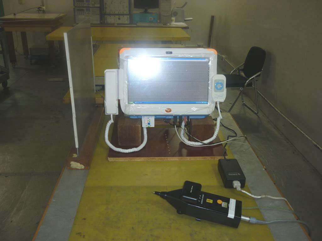
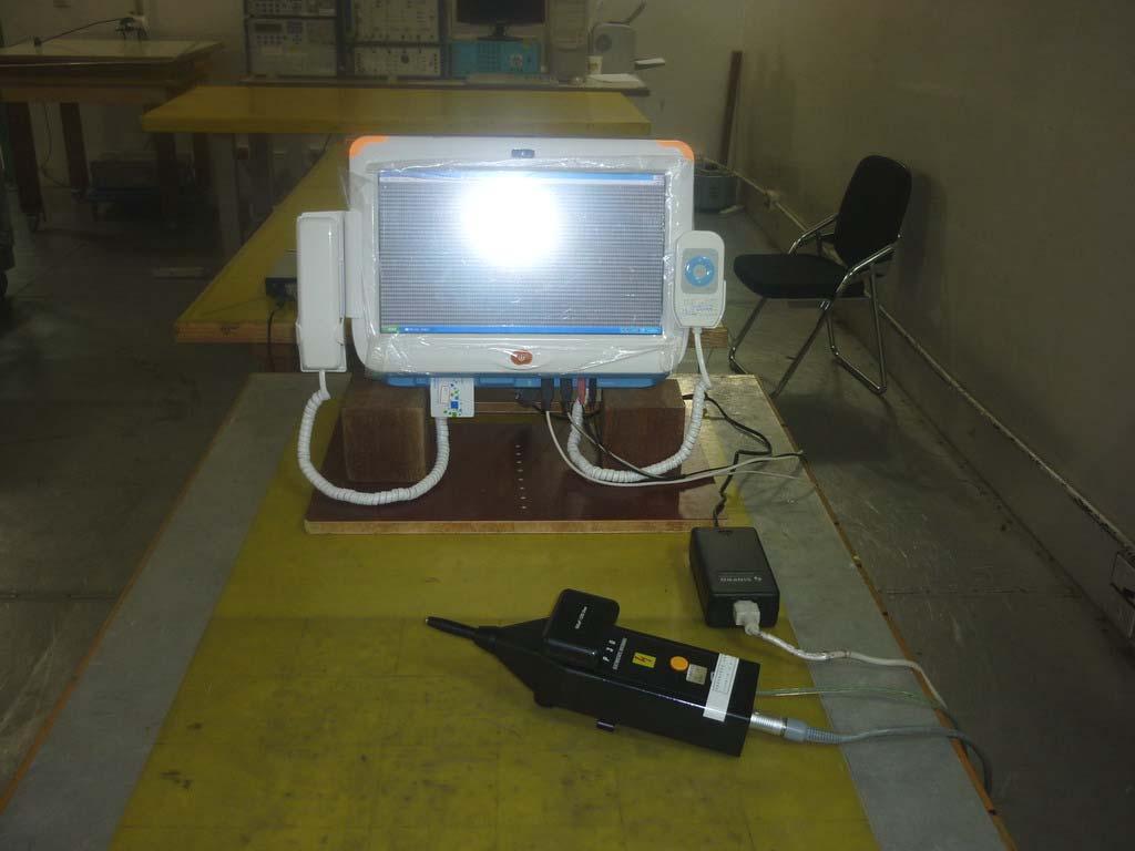
62 RADIATED ELECTROMAGNETIC FIELD TEST FAST TRANSIENTS/BURST TEST Page 61
 Page 62")
63 SURGE IMMUNITY TEST CONDUCTED DISTURBANCE, INDUCED BY RADIO-FREQUENCY FIELDS TEST (MAIN PORT) Page 62
")
64 CONDUCTED DISTURBANCE, INDUCED BY RADIO-FREQUENCY FIELDS TEST (USB PORT) CONDUCTED DISTURBANCE, INDUCED BY RADIO-FREQUENCY FIELDS TEST (COM PORT) Page 63

65 POWER FREQUENCY MAGENTIC FIELD IMMUNITY TEST VOLTAGE DIPS / INTERRUPTION TEST Page 64
66 APPENDIX 1: PHOTOGRAPHS OF EUT Refer to T120229L03 External Photographs. Page 65


67 Reference No: T Report No: T120229L03 PHOTOGRAPHS OF EUT Type 1 Page 1 / 4 Rev.01

68 Reference No: T Report No: T120229L03 Type 2 Page 2 Rev.01


69 Reference No: T Report No: T120229L03 SINPRO / MPU Page 3 Rev.01

70 Reference No: T Report No: T120229L03 Page 4 Rev.01
FCC 47 CFR PART 15 SUBPART B TEST REPORT
 FCC 47 CFR PART 15 SUBPART B TEST REPORT for 10.4 Rugged Tablet PC Model: R10V28M-VMXXXX (X=A~Z, a~z, 0 ~9, Blank or Slash) Test Report Number: 80808002-D Issued for Winmate Communication INC. 9F, No.
FCC 47 CFR PART 15 SUBPART B TEST REPORT
 FCC 47 CFR PART 15 SUBPART B TEST REPORT for 19 Multimedia LCD Monitor MODEL: R19LXXX-IPXXXX (X=A~Z, a~z, 0 ~9, Blank or Slash) Test Report Number: 90406001-D Issued for Winmate Communication INC. 9F,
C-Tick EMC TEST REPORT. For. AC/DC Switching Power Supply
 C-Tick EMC TEST REPORT For AC/DC Switching Power Supply Model: CP0515(5V/1.5A); CP0520(5V/2A); CP0530 (5V/3A); CP0540 (5V/4A); CP0550 (5V/5A); CP0560 (5V/6A);CP0615(6V/1.5A); CP0620(6V/2A); CP0625 (6V/2.5A);
FCC 47 CFR PART 15 SUBPART B TEST REPORT. For. External USB 2.0 HDD Enclosure
 FCC 47 CFR PART 15 SUBPART B TEST REPORT For External USB 2.0 HDD Enclosure Model: AV300, AV500, LD300; AP35USL; EN318UHCR; EMV18BK; EMV18SL; EMV25BK; EMV25SL; EMV35BK; EMV35DBK; EMV35DSL; EMV35SL; ENAP25C;
CE EMC TEST REPORT. for. 8.4 G-WIN Rugged Panel PC MODEL: R08A83X-VMXXXX (X=A~Z, a~z, 0~9, Blank or Slash) Test Report Number: E.
 Test Report Number: E.") CE EMC TEST REPORT for 8.4 G-WIN Rugged Panel PC MODEL: R08A83X-VMXXXX (X=A~Z, a~z, 0~9, Blank or Slash) Test Report Number: 80625001-E Issued for Winmate Communication INC. 9F, No. 111-6, Shing-De Rd.,
CE EMC TEST REPORT for 8.4 G-WIN Rugged Panel PC MODEL: R08A83X-VMXXXX (X=A~Z, a~z, 0~9, Blank or Slash) Test Report Number: 80625001-E Issued for Winmate Communication INC. 9F, No. 111-6, Shing-De Rd.,
CE EMC TEST REPORT. for. IPC Model: IPC-619S; IPC-619XXXXXXXXXXXX; SYS-4U619X-XXXXXXXXXX (X = 0-9, A-Z or Blank) Test Report Number: E
 Test Report Number: E") CE EMC TEST REPORT for IPC Model: IPC-619S; IPC-619XXXXXXXXXXXX; SYS-4U619X-XXXXXXXXXX (X = 0-9, A-Z or Blank) Test Report Number: 90921102-E Issued for Advantech Co. Ltd. No.1, Alley 20, Lane 26, Rueiguang
CE EMC TEST REPORT for IPC Model: IPC-619S; IPC-619XXXXXXXXXXXX; SYS-4U619X-XXXXXXXXXX (X = 0-9, A-Z or Blank) Test Report Number: 90921102-E Issued for Advantech Co. Ltd. No.1, Alley 20, Lane 26, Rueiguang
EMC TEST REPORT For MPP SOLAR INC Inverter/ Charger Model Number : PIP 4048HS
 EMC-E20130903E EMC TEST REPORT For MPP SOLAR INC Inverter/ Charger Model Number : PIP 4048HS Prepared for : MPP SOLAR INC Address : 4F, NO. 50-1, SECTION 1, HSIN-SHENG S. RD. TAIPEI, TAIWAN Prepared by
FCC 47 CFR PART 15 SUBPART B
 FCC 47 CFR PART 15 SUBPART B TEST REPORT For DC TO DC CONVERTER Model : D100 Series Issued for MicroPower Direct, LLC 232 Tosca Drive Stoughton, MA02072 U.S.A. Issued by Compliance Certification Services
CE EMC Test Report GUANGZHOU DMKEMOTOR CO. LTD
 CE REPORT CE EMC Test Report Equipment under Test: Model /Type: Applicant: Address: Manufacturer: Address: Laboratory: Address: Report Number Brush D.C. Motor D5D120-24GU D2D10-12GN, D2D10-24GN, D2D10-36GN,
FCC CLASS B COMPLIANCE REPORT (DoC)
") FCC CLASS B COMPLIANCE REPORT (DoC) for Electromagnetic Emissions Of ENTRY LEVEL IP PHONE Trade Name : XONTEL Model Number : XT-19P Serial Number : N/A Report Number : PZD1611741-F Date : Regulations :
FCC CLASS B COMPLIANCE REPORT (DoC) for Electromagnetic Emissions Of ENTRY LEVEL IP PHONE Trade Name : XONTEL Model Number : XT-19P Serial Number : N/A Report Number : PZD1611741-F Date : Regulations :
EMC TEST REPORT. For. Switching Mode Power Adaptor. Model No.: 9W/14.4V/EU(18V/1.0A), 19W/14.4V/EU(12V/1.5A)
, 19W/14.4V/EU(12V/1.5A)") EMC TEST REPORT For Company Limited Liability «Faraday Electronics» Switching Mode Power Adaptor Model No.: 9W/14.4V/EU(18V/1.0A), 19W/14.4V/EU(12V/1.5A) Prepared For : Company Limited Liability «Faraday
EMC TEST REPORT For Company Limited Liability «Faraday Electronics» Switching Mode Power Adaptor Model No.: 9W/14.4V/EU(18V/1.0A), 19W/14.4V/EU(12V/1.5A) Prepared For : Company Limited Liability «Faraday
EMC TEST REPORT. Report No.: CE10-LIE040101E
 EMC TEST REPORT Report No.: CE10-LIE040101E Product: LED TUBE Model No.: T10, T8, T5 Applicant: Shenzhen Saiju Electronic Co., Ltd. Address: 2nd. Xianshun Industrial Park, Gushu, Xixiang, Bao an, Shenzhen,
VCCI TEST REPORT. for. Communication Appliance
 VCCI TEST REPORT for Communication Appliance MODEL: ODS-VL2-8; ODS-VL2-8-2AC; ODS-VL2-8-DC; ODS-VL2-8-2DC; ODS-VL2-XL-8; ODS-VL2-XL-8-2A; ODS-VL2-XL-8-DC; ODS-VL2-XL-8-2D; ODS-VL2-16; ODS-VL2-16-2AC; ODS-VL2-16-DC;
CE EMC TEST REPORT. For. ATX Power Supply Tester. Model: POWER JUDGE ; TEST-ALIM-ATX-20/24 ; PSTESTER-1. Trade Name: Connectland ; POWMAX.
 CE EMC TEST REPORT For ATX Power Supply Tester Model: POWER JUDGE ; TEST-ALIM-ATX-20/24 ; PSTESTER-1 Trade Name: Connectland ; POWMAX Issued for COMING DATA CO., LTD. 5F-1, NO. 13, WU CHUNG 1RD, HSIN CHUNG
for Issued for Supremevalue Technology CO., Ltd 4/F,A4 Bldg.,Yinlong Industrial Park,292# Shenshan Rd,518116, Longgang District,Shenzhen,China.
 EMC TEST REPORT for Product: Car Charger Trade Mark: MEKNIC Model: SV-PC01,SV-PC02,SV-PC03,SV-PC04,SV-PC05, SV-PC06,SV-PC07,SV-PC08,SV-PC09,SV-PC10, SV-PC11,SV-PC12,SV-PC13,SV-PC14,SV-PC15, SV-PC16,SV-PC17,SV-PC18,SV-PC19,SV-PC20
CE TEST CERTIFICATION
 according to Certification No.: E5NC004 European Standard EN 61000-6-4:2001 EN 61000-3-2: 2000, EN 61000-3-3:1995/A1:2001 and EN 61000-6-2:2001 ( IEC 61000-4-2:1995/A1:1998, IEC 61000-4-3: 1995/A1:1998,
CE EMC Test Certification
 Certification No.: EC57C001 CE EMC Test Certification According to European Standard EN 55022:1998/A1:2000/A2:2003 Class A, EN 61000-3-2: 2000, EN 61000-3-3:1995/A1:2001 and EN 55024:1998/A1:2001/A2:2003
CE TEST CERTIFICATION
 Certification No.: E5DC001 according to European Standard EN 61000-6-4:2001 EN 61000-3-2: 2000, EN 61000-3-3:1995/A1:2001 and EN 61000-6-2:2001 ( IEC 61000-4-2:1995/A1:1998, IEC 61000-4-3: 1995/A1:1998,
FCC VERIFICATION TEST REPORT
 FCC VERIFICATION TEST REPORT for 2.4GHz Digital Headphone Model: DHP380, DHP380A Marketing Name: ADH300 Brand: ARKON Test Report Number: C170526Z02-F Issued for: ARKON ELECTRONICS(HUIZHOU)CO.,LIMITED NO.4
No. 620 HuaYuan Commercial Center, No. 347 XiXiang Road,XiXiang Town, Bao An District, ShenZhen City Tel : Fax:
 No. 620 HuaYuan Commercial Center, No. 347 XiXiang Road,XiXiang Town, Bao An District, ShenZhen City Tel : +86-755-27912080 Fax: +86-755-27916936 FCC TEST REPORT Product name : 7PORT DUAL SUPPLY POE SWITCH
ELECTRONICS TESTING CENTER(ETC), TAIWAN
, TAIWAN") File No. : 06-03-RBF-111-01 EMC TESTING DEPARTMENT II Page: 1 / 35 TEST REPORT Responsible Party Manufacturer Description of Product Trade Name : Huan Vu Enterprise Co., Ltd. : Huan Vu Enterprise Co.,
File No. : 06-03-RBF-111-01 EMC TESTING DEPARTMENT II Page: 1 / 35 TEST REPORT Responsible Party Manufacturer Description of Product Trade Name : Huan Vu Enterprise Co., Ltd. : Huan Vu Enterprise Co.,
FCC Verification TEST REPORT
 FCC Verification TEST REPORT Product: 5 in 1 Environment Meter Model no.: ET-965 Trade Mark: N/A Report No.: TCT140915E005 Issued Date: Sep. 22, 2014 Issued for: Shenzhen Flus Technology Co., Ltd 3rd Floor,
TEST REPORT... 1 CONTENT...
 CONTENT TEST REPORT... 1 CONTENT... 2 1 TEST RESULTS SUMMARY... 3 2 EMC RESULTS CONCLUSION... 4 3 LABORATORY MEASUREMENTS... 6 4 EMI TEST... 7 4.1 CONTINUOUS CONDUCTED DISTURBANCE VOLTAGE TEST... 7 4.2
Harmonic Current emission EN :2014 Class A Pass. Voltage Fluctuation and Flicker EN :2013 Clause 5 Pass
 Reference No.: WTS15F0323845E Page 2 of 33 1 Test Summary Test Item Mains Terminal Disturbance Voltage, 148.5kHz to 30MHz Disturbance Power, 30MHz to 300MHz Discontinuous Disturbance (Click) Radiated Emission,
EN 55022: 2010+AC:2011 Clause 6.1 Pass. Harmonic Current EN :2006+A1:2009+A2:2009 Class A N/A
 Reference No.: WT12106773-N-S-E Page 2 of 33 1 Test Summary Test Item Mains Terminal Disturbance Voltage, 150KHz to 30MHz Radiation Emission, 30MHz to 1000MHz EMISSION Test Standard Class / Severity Result
EMC TEST REPORT. ADDRESS : #2 Creation Rd. 4, Science-Based Ind. Park Hsinchu Taiwan, R.O.C.
 EMC TEST REPORT REPORT NO. : RM110613E07 MODEL NO. : M-R0027 RECEIVED : June 13, 2011 TESTED : June 17, 2011 ISSUED : June 22, 2011 APPLICANT : LOGITECH FAR EAST LTD. ADDRESS : #2 Creation Rd. 4, Science-Based
Discontinuous Disturbance (Click) EN :2006+A1:2009+A2:2011 Clause N/A** Radiated Emission, 30MHz to 1000MHz
 EN :2006+A1:2009+A2:2011 Clause N/A** Radiated Emission, 30MHz to 1000MHz") Reference No.: WTN13F0706038E Page 2 of 40 1 Test Summary Test Item Mains Terminal Disturbance Voltage, 148.5kHz to 30MHz Disturbance Power, 30MHz to 300MHz EMISSION Test Standard Class / Severity Result
Reference No.: WTN13F0706038E Page 2 of 40 1 Test Summary Test Item Mains Terminal Disturbance Voltage, 148.5kHz to 30MHz Disturbance Power, 30MHz to 300MHz EMISSION Test Standard Class / Severity Result
CE EMC TEST REPORT. For EMERGENCY BATTERY KIT V-TAC EXPORTS LIMITED V-TAC EXPORTS LIMITED. Global-Standard Testing Service Co., Ltd.
 CE EMC TEST REPORT For EMERGENCY BATTERY KIT Model No.: VT-510, VT-514, VT-515, VT-518, VT-530, VT-511, VT-503 Applicant : V-TAC EXPORTS LIMITED ROOM NO.301, KAM ON BUILDING 176A QUEENS ROAD CENTRAL, CENTRAL,
EMC TEST REPORT. according to
 EMC TEST REPORT according to European Standard EN 55022:2006/A1:2007 Class B, EN 61000-3-2:2006, EN 61000-3-3:1995/A1:2001/A2:2006, EN 55024:1998/A1:2001/A2:2003 (IEC 61000-4-2:Edition 1.2:2001-04, IEC
ITUNER NETWORKS CORPORATION EMC REPORT Fremont Blvd. Fremont, CA
 Shenzhen BST Technology Co., Ltd. ITUNER NETWORKS CORPORATION EMC REPORT Prepared For : ITUNER NETWORKS CORPORATION 47801 Fremont Blvd. Fremont, CA. 94538 Product Name: PicoPSU-150 Trade Name: PicoPSU
CE EMC TEST REPORT. for. HDPro MODEL: HDPro. Test Report Number: E. Issued to: CalDigit Miraloma Ave. #B Placentia, CA 92870
 CE EMC TEST REPORT for HDPro MODEL: HDPro Test Report Number: 80910213-E Issued to: CalDigit 1941 Miraloma Ave. #B Placentia, CA 92870 Issued by: Compliance Certification Services Inc. Sindian BU. No.163-1,
EN 55015: 2013 Clause Pass. EN 55015: 2013 Clause Pass. EN 55015: 2013 Clause Pass
 Reference No.: WTD15S0730643E Page 2 of 42 1 Test Summary Test Item Conducted Disturbance at Mains Terminal, 9kHz to 30MHz Radiation electromagnetic disturbance, 9kHz to 30MHz Radiation Emission, 30MHz
TEST SUMMARY. Prüfbericht - Nr.: Test Report No.: Seite 2 von 27. Page 2 of 27
 15072768 001 Seite 2 von 27 Page 2 of 27 TEST SUMMARY 4.1.1 HARMONICS ON AC MAINS 4.1.2 VOLTAGE CHANGES, VOLTAGE FLUCTUATIONS AND FLICKER ON AC MAINS 4.1.3 MAINS TERMINAL CONTINUOUS DISTURBANCE VOLTAGE
EMC Test Report For Changzhou Airwheel Technology Co.,Ltd. Airwheel Model: A6S,A6,A6P,A6PS,A6T,A6TS
 EMC Test Report For Changzhou Airwheel Technology Co.,Ltd. Airwheel Model: A6S,A6,A6P,A6PS,A6T,A6TS Prepared For : Prepared By : Changzhou Airwheel Technology Co.,Ltd. Fl.5, East of No. 10 Building, high-tech
2620 Modular Measurement and Control System
 European Union (EU) Council Directive 89/336/EEC Electromagnetic Compatibility (EMC) Test Report 2620 Modular Measurement and Control System Sensoray March 31, 2006 April 4, 2006 Tests Conducted by: ElectroMagnetic
CERTIFICATE. Issued Date: Apr. 20, 2006 Report No.: 064L079-IT-US-P01V01
 CERTIFICATE Issued Date: Apr. 20, 2006 Report No.: 064L079-IT-US-P01V01 This is to certify that the following designated product Product : 19 inch Rack-mounted Data Acquisition Computer Trade name : Moxa
EMC Test Report. Report Number: M030826
 Page 1 of 36 EMC Technologies Pty Ltd ABN 82 057 105 549 57 Assembly Drive Tullamarine Victoria Australia 3043 Ph: + 613 9335 3333 Fax: + 613 9338 9260 email: melb@emctech.com.au EMC Test Report Report
Certificate of Test AND KEEPS ALL REQUIREMENTS ACCORDING THE FOLLOWING REGULATIONS IEC :2001 IEC :2007
 Certificate of Test WE HEREBY CERTIFY THAT: Certificate No.: R07122709E Yuan Hsun Electric Co., Ltd. No. 57, Chung He Rd, Zuo-Ying Dist., Kaohsiung City 813, Taiwan R.O.C. Quad photobeam detector Quad-200CS
TEST SUMMARY. Prüfbericht - Nr.: Test Report No.: Seite 2 von 25. Page 2 of 25
 15072259 001 Seite 2 von 25 Page 2 of 25 TEST SUMMARY 4.1.1 HARMONICS ON AC MAINS 4.1.2 VOLTAGE FLUCTUATIONS ON AC MAINS 4.1.3 MAINS TERMINAL CONTINUOUS DISTURBANCE VOLTAGE 4.1.4 DISCONTINUOUS INTERFERENCE
EMC TEST REPORT. for. Coliy Technology Co.,Ltd. Fluxgate Gaussmeter
 Page 1 of 48 EMC TEST REPORT for Coliy Technology Co.,Ltd. Fluxgate Gaussmeter Prepared for : Coliy Technology Co.,Ltd. Address : Block B,9 th Floor,Xinzhongtai Business Building,Gushu 2nd Road,Xi Town,Bao
Discontinuous Disturbance (Click) EN : 2011 Clause Pass Radiated Emission, 30MHz to 1000MHz
 EN : 2011 Clause Pass Radiated Emission, 30MHz to 1000MHz") Reference No.: WTU15U0933879E Page 2 of 45 1 Test Summary Test Item Mains Terminal Disturbance Voltage, 148.5kHz to 30MHz Disturbance Power, 30MHz to 300MHz EMISSION Test Standard Class / Severity Result
Reference No.: WTU15U0933879E Page 2 of 45 1 Test Summary Test Item Mains Terminal Disturbance Voltage, 148.5kHz to 30MHz Disturbance Power, 30MHz to 300MHz EMISSION Test Standard Class / Severity Result
EMC REPORT. ShenZhen KY Technology Co.,Ltd. No.369, BaoTian 1st RD, TieGang Industrial Park, Xixiang Town, Baoan District, ShenZhen, PRC.
 Report No.: UNI2016121702ER-01 Page 1 / 30 ShenZhen KY Technology Co.,Ltd EMC REPORT Prepared For: ShenZhen KY Technology Co.,Ltd Product Name: Smart bracelet No.369, BaoTian 1st RD, TieGang Industrial
APPLICATION FOR EMC DIRECTIVE. On Behalf of. Shenzhen Qinhan Lighting Co., Ltd. led flood light. Trade Name:
 APPLICATION FOR EMC DIRECTIVE On Behalf of Shenzhen Qinhan Lighting Co., Ltd led flood light Trade Name: Model: QH-TGC-400W, QH-TGC-300W, QH-TGC-500W, QH-TGC-800W, QH-TGC-1000W Prepared For : Shenzhen
Overview of EMC Regulations and Testing. Prof. Tzong-Lin Wu Department of Electrical Engineering National Taiwan University
 Overview of EMC Regulations and Testing Prof. Tzong-Lin Wu Department of Electrical Engineering National Taiwan University What is EMC Electro-Magnetic Compatibility ( 電磁相容 ) EMC EMI (Interference) Conducted
Test Report. Guangdong East Power Co., Ltd. Fully Automatic AC Voltage Regulator. Brand Name:
 Test Report Applicant: Product Name: Brand Name: Model No.: Guangdong East Power Co., Ltd. Fully Automatic AC Voltage Regulator EAST ZTY-30KVA Date of Receipt : Aug. 30, 2013 Date of Test: Sep. 03, 2013
CE EMC TEST REPORT. For IPC. Model: ACP Trade Name: ADVANTECH. Issued for
 CE EMC TEST REPORT For IPC Model: ACP-2320 Trade Name: ADVANTECH Issued for Advantech Co., Ltd. No. 1, Alley 20, Lane 26, Rueiguang Road, Neihu District, Taipei 114, Taiwan, R.O.C. Issued by Compliance
TEST REPORT. Product: Thermo-Hygrometer Model No.: FL-201, FL-201W Trade mark: N/A Report No.: TCT151014E001 Issued Date: Oct. 15, 2015.
 TEST REPORT Product: Thermo-Hygrometer Model No.: FL-201, FL-201W Trade mark: N/A Report No.: TCT151014E001 Issued Date: Oct. 15, 2015 Issued for: Shenzhen Flus Technology Co., Ltd 3rd Floor, Lantian Building,
CE EMC TEST REPORT. For. Panel PC. Model: PPC-153M. Trade Name: ADVANTECH. Issued for. Advantech Co., Ltd.
 CE EMC TEST REPORT For Panel PC Model: PPC-153M Trade Name: ADVANTECH Issued for Advantech Co., Ltd. No. 1, Alley 20, Lane 26, Rueiguang Road, Neihu District, Taipei 114, Taiwan, R.O.C. Issued by COMPLIANCE
TEST SUMMARY Seite 2 von 27. Prüfbericht - Nr.: Test Report No HARMONICS ON AC MAINS RESULT: Passed
 17035561 001 Seite 2 von 27 Page 2 of 27 TEST SUMMARY 5.1.1 HARMONICS ON AC MAINS RESULT: Passed 5.1.2 VOLTAGE FLUCTUATIONS ON AC MAINS RESULT: Passed 5.1.3 TERMINAL CONTINUOUS DISTURBANCE VOLTAGE AT RESULT:
1 SUMMARY OF STANDARDS AND RESULTS
 1 SUMMARY OF STANDARDS AND RESULTS 1.1 Description of Standards and Results The EUT have been tested according to the applicable standards as referenced below: EMISSION Description of Test Item Standard
CE EMC CERTIFICATION
 according to Certification No.: EC78C004-01 European Standard EN 55022:2006 Class A, EN 61000-3-2:2000, EN 61000-3-3:1995/A1:2001 and EN 55024:1998/A1:2001/A2:2003 ( IEC 61000-4-2:1995/A2:2000, IEC 61000-4-3:2002,
EMC TEST REPORT for : DONGGUAN EVER DEVELOPMENT ELECTRONIC CO., Electronic calculator Model No.: KF15758
 Page 1 of 20 Report No. R011604553E EMC TEST REPORT for DONGGUAN EVER DEVELOPMENT ELECTRONIC CO., LTD. Electronic calculator Model No.: KF15758 Prepared for Address Prepared by Address : DONGGUAN EVER
Page: 1 of 20 EMC TEST REPORT EN55024:1998+A2:2003
 Page: 1 of 20 EMC TEST REPORT Reference No. Applicant : WT05060412 : Gembird Electronics Ltd. Equipment Under Test (EUT) : Product Name : Cable Standards Model No : UAS111-M, UAS111, UAS112 : EN55022:1998+A2:2003
Test Report GUANGDONG EAST POWER CO., LTD
 Test Report Applicant: Product Name: Brand Name: Model No.: GUANGDONG EAST POWER CO., LTD Online High Frequency UPS EAST EA906IIRTS, EA906IIRTH Date of Receipt : Feb. 26, 2014 Date of Test: Mar. 24, 2014
TABLE OF CONTENTS. Report Reference No.: GST E Issued: Oct. 21, 2011 Revised: None. Page 2 of 46
 TABLE OF CONTENTS 1. GENERAL INFORMATION...5 1.1 PRODUCT DESCRIPTION FOR EQUIPMENT UNDER TEST (EUT)...5 1.2 OBJECTIVE...5 1.3 RELATED SUBMITTAL(S)/GRANT(S)...5 1.4 TEST METHODOLOGY...5 1.5 TEST FACILITY...5
EMC TEST REPORT For INNOKIN TECHNOLOGY CO., LIMITED. ITaste vv. Model No.: ITaste vv
 EMC TEST REPORT For INNOKIN TECHNOLOGY CO., LIMITED ITaste vv Model No.: ITaste vv Prepared for : INNOKIN TECHNOLOGY CO., LIMITED Address : 3# Floor, #B Building, Heng Chang Rong Industrial Park, Gonghe
Test Report. Product Name: Wireless 11g USB Adapter Model No. : MS-6826, UB54G FCC ID. : DoC
 Test Report Product Name: Wireless 11g USB Adapter Model No. : MS-6826, UB54G FCC ID. : DoC Applicant : MICRO-STAR INT L Co., LTD Address : No 69, Li-De st., Jung-He City, Taipei Hsien, Taiwan, R.O.C Date
EMC TEST REPORT for LEDELS LIGHTING CO., LTD. LED module Model No. : LL-F12T4815X6B
 Page 1 of 27 Report No. R011412016E-1 EMC TEST REPORT for LEDELS LIGHTING CO., LTD LED module Model No. : LL-F12T4815X6B Prepared for : LEDELS LIGHTING CO., LTD Address : 5F, Block C, Mingjinhai Ind. Park,
TEST REPORT. Table of Contents
 Page:2 of 28 Table of Contents 1. DOCUMENT POLICY AND TEST STATEMENT... 3 1.1 DOCUMENT POLICY... 3 1.2 TEST STATEMENT... 3 2. DESCRIPTION OF EUT AND TEST MODE... 4 2.1 GENERAL DESCRIPTION OF EUT... 4 2.2
EMC Test Report FATEK AUTOMATION CORP. FATEK. FBs-TBOX N/A
 EMC Test Report Applicant: Address of Applicant: Trade Name: FATEK AUTOMATION CORP. 26FL, NO.29, SEC.2, JUNGJENG E. RD., DANSHUEI DIST., NEW TAIPEI CITY, TAIWAN, R.O.C. FATEK Equipment Under Test: Training
EMC COMPLIANCE TEST REPORT
 EMC COMPLIANCE TEST REPORT Technical Statement of Conformity in accordance with the council directive 2004/108/EC The product Equipment Under Test Model Number Product Series Report Number Issue Date Test
CONFORMANCE TEST REPORT FOR EN /-6
 CONFORMANCE TEST REPORT FOR EN 301489-1/-6 Client: Product: Model: Manufacturer/supplier: Aztech Systems Limited DECT Phone H315-S1 (FP) Aztech Systems Limited Date test item received: 2006/05/09 Date
EMC TEST REPORT For. Shenzhen Ruideou Keji Youxian Gongsi. Shenzhen Ruideou Keji Youxian Gongsi
 EMC TEST REPORT For Shenzhen Ruideou Keji Youxian Gongsi Product Name: Trademark: Milligram Scale WAOAW Model Number: W-01-50 Prepared For : Address: Prepared By : Address: Shenzhen Ruideou Keji Youxian
EMC REPORT DONGGUAN FIT-WATCH CO., LTD. 18#,Hedong No.1 road,jinsha village,changan town, Dongguan City, Guangdong Province.
 DONGGUAN FIT-WATCH CO., LTD. EMC REPORT Prepared For : DONGGUAN FIT-WATCH CO., LTD. 18#,Hedong No.1 road,jinsha village,changan town, Dongguan City, Guangdong Province Product Name : Trade Name : Model
EMC Testing Report. Dual-120CS. Yuan Hsun Electric Co., Ltd.
 EMC Testing Report Equipment Under Test: Model Number: Serial No.: Applicant: Address of Applicant: Multi-Frequency (4 Channel Selectable) Twin Photobeam Detector Dual-120CS Dual-90CS, Dual-60CS, Dual-30CS
TEST REPORT. Table of Contents
 Page:2 of 24 Table of Contents 1. DOCUMENT POLICY AND TEST STATEMENT... 3 1.1 DOCUMENT POLICY...3 1.2 TEST STATEMENT...3 2. DESCRIPTION OF EUT AND TEST MODE... 4 2.1 GENERAL DESCRIPTION OF EUT...4 2.2
FCC DOC TEST REPORT. According to. 47 CFR, Part 2, Part 15, CISPR PUB. 22, ICES 003 Issue 6
 FCC DOC TEST REPORT According to 47 CFR, Part 2, Part 15, CISPR PUB. 22, ICES 003 Issue 6 Applicant Address Equipment Model No. Trade Name : Panasonic India Pvt. Ltd. : 6th Floor, "SPIC BUILDING" Annexe,
Shenzhen Toby Technology Co., Ltd. EMC Test Report. Report No.: TB-EMC Page: 1 of 20
 Shenzhen Toby Technology Co., Ltd. Report No.: TB-EMC125641 Page: 1 of 20 EMC Test Report Application No. : TB12114299 Applicant : Newmb Technology Co., Ltd. Equipment Under Test (EUT) EUT Name : USB HUB
Test Report. Product Name : IPC Model No.
 Test Report Product Name : IPC Model No. : On Demand Switch 3 (RODS3-DEFAULT) On Demand Switch 3 (RODS3-S1-DEFAULT) On Demand Switch 3 (RODS3-S2-DEFAULT) Applicant : Radware Ltd. Address : 22 Raoul Wallenberg
TABLE OF CONTENTS 1. GENERAL DESCRIPTION OF EUT 3 2. GENERAL INFORMATION OF TEST CONDUCTED EMISSION TEST RADIATED EMISSION TEST 11
 Page : 2 / 38 TABLE OF CONTENTS 1. GENERAL DESCRIPTION OF EUT 3 2. GENERAL INFORMATION OF TEST 4 3.1 CONDUCTED EMISSION TEST 7 3.2 RADIATED EMISSION TEST 11 3.3 ELECTROSTATIC DISCHARGE IMMUNITY TEST 14
EMC TEST REPORT. According to
 EMC TEST REPORT According to EN 55022:2006/A1:2007 (Class B) EN 55024 : 1998/ A1:2001/ A2:2003 EN 61000-3-2 : 2006/A1:2009/A2:2009 IEC 61000-4-2 : 2008 EN 61000-3-3 : 2008 IEC 61000-4-3 : 2010 IEC 61000-4-4
Prepared for Address. : KST DIGITAL TECHNOLOGY LIMITED : No.226, Pangu Street, Meixian, Meizhou, Guangdong. Prepared by
 EMC TEST REPORT For KST DIGITAL TECHNOLOGY LIMITED Coreless Servo Model No.: X12-508 Additional Model No.: DS215MG, DS315MG, DS213MG, DS313MG, DS12C, DS12T, X12-306 Prepared for Address : KST DIGITAL TECHNOLOGY
Report for Excelsys EMC Measurements for 4Xgen Purchase Order: Project Number EMT07J026 Rev. B
 Report for Excelsys on EMC Measurements for 4Xgen Purchase Order: Project Number EMT07J026 Rev. B Rev Date Comment A April 2007 Change in DoC content B May 2007 Added Immunity Section EMT is a TÜV Appointed
EMC standards. Presented by: Karim Loukil & Kaïs Siala
 Training Course on Conformity and Interoperability on Type Approval testing for Mobile Terminals, Homologation Procedures and Market Surveillance, Tunis-Tunisia, from 20 to 24 April 2015 EMC standards
VCCI TEST REPORT. According to. Class B ITE. Equipment : USB video camera
 VCCI TEST REPORT According to Class B ITE Equipment : USB video camera Model No. : V-U0011 Applicant : Logitech Far East Ltd. 2 Creation Road IV, Science-Based Ind. Park, Hsinchu, Taiwan. The test result
Test Report. : 09A255R-ITCEP28V01 Report Version : V1.0
 Established 1981 Advanced Test Equipment Rentals www.atecorp.com 800-404-ATEC (2832) Test Report Product Name : Industrial IEEE 802.11a/b/g dual-rf Access Point/Bridge/Client Model No. : AWK-6222-xx-y
CE EMC TEST REPORT. Model Name: JZH-RF898B JZH-RX898B Report No.: BCTC E. Prepared for
 Shenzhen BCTC Technology Co., Ltd. Report No.: BCTC-160608172-2E CE EMC TEST REPORT Product: Fishing bite alarm Trade Name: Model Name: JZH-RF898B JZH-RX898B Report No.: BCTC-160608172-2E Prepared for
C E R T I F I C A T I O N
 C E R T I F I C A T I O N Applicant Address Manufacturer Address : American Power Conversion Holding Inc. Taiwan Branch : 3F., No. 205, Sec. 3, Beixin Rd., Xindian Dist., New Taipei City 231, Taiwan R.O.C.
EN v3.1.1 TEST REPORT FOR. Bluetooth Serial Port Module MODEL NUMBER: LMX9838 REPORT NUMBER: 14U17620-E1V3 ISSUE DATE: AUGUST 31, 2017
 EN 301 489-17 v3.1.1 TEST REPORT FOR Bluetooth Serial Port Module MODEL NUMBER: LMX9838 REPORT NUMBER: 14U17620-E1V3 ISSUE DATE: AUGUST 31, 2017 Prepared for Texas Instrument 2900 Semiconductor Drive Santa
CERTIFICATE. Issued Date: Apr. 02, 2009 Report No.: R-ITUSP01V01
 CERTIFICATE Issued Date: Apr. 02, 2009 Report No.: 093337R-ITUSP01V01 This is to certify that the following designated product Product : 2G 8/16PORT Serial Device Server Trade name : Moxa Model Number
FCC CLASS B COMPLIANCE REPORT (DOC)
") Page : 1 of 17 FCC CLASS B COMPLIANCE REPORT (DOC) Test Report No. : EM/2003/20077 Applicant/Factory : Moxa Technologies Co., Ltd. Address of Applicant : Fl. 4, No. 135, Lane 235, Pao-Chiao Rd., Shing
Page : 1 of 17 FCC CLASS B COMPLIANCE REPORT (DOC) Test Report No. : EM/2003/20077 Applicant/Factory : Moxa Technologies Co., Ltd. Address of Applicant : Fl. 4, No. 135, Lane 235, Pao-Chiao Rd., Shing
EMC TEST REPORT for SHENZHEN MUST ENERGY TECHNOLOGY CO., LTD
 Page 1 of 45 Report No. R011607240E EMC TEST REPORT for SHENZHEN MUST ENERGY TECHNOLOGY CO., LTD INVERTER CHARGER Model No.: PV35-4K DC24V MPK, PV35-4K DC48V MPK, PV35-5K DC48V MPK, PV35-6K DC48V MPK Prepared
C E R T I F I C A T I O N
 C E R T I F I C A T I O N Applicant Address Manufacturer Address :American Power Conversion Holding Inc. Taiwan Branch :3F., No. 205, Sec. 3, Beixin Rd., Xindian Dist., New Taipei City 231, Taiwan R.O.C.
ETSI EN V1.2.1: 2002 TEST REPORT. For. Bluetooth USB Hub. Model: MS Trade Name: MSI. Issued to
 ETSI EN 301 489-17 V1.2.1: 2002 TEST REPORT For Bluetooth USB Hub Model: MS-6871 Trade Name: MSI Issued to MICRO-STAR INT'L CO., LTD. NO. 69, Li-De St, Jung-He City, Taipei Hsien, Taiwan, R.O.C. Issued
EN v1.2.1 ( ) TEST REPORT FOR b/g PCIExpress Minicard MODEL NUMBER: AR5BXB63 REPORT NUMBER: 06U
 TEST REPORT FOR b/g PCIExpress Minicard MODEL NUMBER: AR5BXB63 REPORT NUMBER: 06U") EN 301 489-17 v1.2.1 (2002-08) TEST REPORT FOR 802.11b/g PCIExpress Minicard MODEL NUMBER: AR5BXB63 REPORT NUMBER: 06U10459-6 ISSUE DATE: JULY 31, 2006 Prepared for ATHEROS COMMUNICATIONS, INC. 5480 GREAT
EN 301 489-17 v1.2.1 (2002-08) TEST REPORT FOR 802.11b/g PCIExpress Minicard MODEL NUMBER: AR5BXB63 REPORT NUMBER: 06U10459-6 ISSUE DATE: JULY 31, 2006 Prepared for ATHEROS COMMUNICATIONS, INC. 5480 GREAT
EMC TEST REPORT. Report No. : EM/2004/10096 Page : 1 of 19
 EMC TEST REPORT Page : 1 of 19 Equipment Under Test Model No. Applicant Address of Applicant : Bluetooth Headset : FB-HS01 : Formosa Teletek Corporation : 358, Huaya 2 nd Rd., Gueishan shiang, Taoyuan,
VCCI TEST REPORT. According to. V-3/ , TECHNICAL REQUIREMENTS, Class B ITE. Equipment : USB video camera. Model No. : V-U0017 / V-U0021
 VCCI TEST REPORT According to V-3/2009.04, TECHNICAL REQUIREMENTS, Class B ITE Equipment : USB video camera Model No. : V-U0017 / V-U0021 Applicant : Logitech Far East Ltd. 2 Creation Road IV, Science-Based
TEST REPORT. Report No. : EM/2008/80003 Page : 1 of 54
 Equipment Under Test Brand Name Model No. Added Model(s) Applicant Address of Applicant Page : 1 of 54 TEST REPORT : AC Servo Motor : Kingservo : AC 400W servo motor : N/A : Ho Fo Automation CO., LTD :
Test Report. Product Name: Cable Modem Model No.: BEFCMU10 ver.3 FCC ID. : Q87-BEFCMU10V3
 Report No. 036H064FI Test Report Product Name: Cable Modem Model No.: BEFCMU10 ver.3 FCC ID. : Q87-BEFCMU10V3 Applicant : Cisco-Linksys, LLC Address : 17401 Armstrong Avenue, Irvine, CA 92614 USA Date
SUZHOU MAILI ELECTRICAL APPLIANCE CO., LTD NO.666,JIANLIN RD, XUGUAN SUBAREA, SUZHOU HIGH-TECH ZONE
 EMC TEST REPORT For SUZHOU MAILI ELECTRICAL APPLIANCE CO., LTD Product Name: Pure sine wave power inverter Trademark: Model : Prepared For : Address: Prepared By : Address: ML-1000W ML-300W---ML-8000W.
EMC TEST REPORT. For. Soma Medical (Sabah) Sdn Bhd ( D) UVGI AIR STERILIZER. Model No.: SM 20
 Sdn Bhd ( D) UVGI AIR STERILIZER. Model No.: SM 20") EMC TEST REPORT For Soma Medical (Sabah) Sdn Bhd (1248058-D) UVGI AIR STERILIZER Model No.: SM 20 Prepared For : Soma Medical (Sabah) Sdn Bhd (1248058-D) : Block E, Lot 28, 2nd floor, Signature Office,
EMC TEST REPORT For Soma Medical (Sabah) Sdn Bhd (1248058-D) UVGI AIR STERILIZER Model No.: SM 20 Prepared For : Soma Medical (Sabah) Sdn Bhd (1248058-D) : Block E, Lot 28, 2nd floor, Signature Office,
MIL STD 461F TEST REPORT. For. Rugged PDA. Model Number: P37B. Trade Name: N/A. Issued to
 MIL STD 461F TEST REPORT For Rugged PDA Model Number: P37B Trade Name: N/A Issued to ACA Digital Corporation 17F.,No 866-7, Zhongzheng Rd, Zhonghe City, Taipei County, 235, Taiwan, R,O,C Issued by Compliance
FCC Part 15 Subpart B
 Report No.: 15A111603E-F Page 1 of 23 Test Report FCC Part 15 Subpart B for Electromagnetic Interference of Product: Managed PoE Industrial Ethernet Switch Trade Name: N/A Model Number: IS-DG512P-2F-8;
Guangdong East Power Co., Ltd. Uninterruptible Power Systems
 Test Report Applicant: Product Name: Brand Name: Model No.: Guangdong East Power Co., Ltd. Uninterruptible Power Systems EAST EA8806, EA8804 Date of Receipt : Nov. 01, 2012 Date of Test: Nov. 03, 2012
EMC TEST REPORT. For. Boardcon Technology Limited. MINI9G45 Computer on Module. Model No. : MINI9G45
 REPORT NO. PRSZ15110502E EMC TEST REPORT For Boardcon Technology Limited. MINI9G45 Computer on Module Model No. : MINI9G45 Prepared For : Boardcon Technology Limited. : Room 702, Hua Feng Xin An Business
CE EMC TEST REPORT. for. Multi-function Pest Repeller MODEL: UP11XX(X=0~9 or A~Z) Test Report Number: T130322D10-E. Issued to:
 Test Report Number: T130322D10-E. Issued to:") CE EMC TEST REPORT for Multi-function Pest Repeller MODEL: UP11XX(X=0~9 or A~Z) Test Report Number: T130322D10-E Issued to: DIGIMAX INNOVATIVE PRODUCTS LTD. 2F., No.196, Sec. 2, Zhongxing Rd., Xindian
CE EMC TEST REPORT for Multi-function Pest Repeller MODEL: UP11XX(X=0~9 or A~Z) Test Report Number: T130322D10-E Issued to: DIGIMAX INNOVATIVE PRODUCTS LTD. 2F., No.196, Sec. 2, Zhongxing Rd., Xindian
ETSI EN V2.2.0 ( ) ETSI EN V2.1.1 ( ) TEST REPORT. United GULF GATE Co.
 ETSI EN V2.1.1 ( ) TEST REPORT. United GULF GATE Co.") ETSI EN 301 489-1 V2.2.0 (2017-03) ETSI EN 301 489-3 V2.1.1 (2017-03) TEST REPORT For United GULF GATE Co. Aladel Tower,F21,Fahad Al Salem St., State of KUWAIT Model: XT-10P Report Type: Amended Report
ETSI EN 301 489-1 V2.2.0 (2017-03) ETSI EN 301 489-3 V2.1.1 (2017-03) TEST REPORT For United GULF GATE Co. Aladel Tower,F21,Fahad Al Salem St., State of KUWAIT Model: XT-10P Report Type: Amended Report
C E R T I F I C A T I O N
 C E R T I F I C A T I O N Applicant Address Manufacturer Address : American Power Conversion Holding Inc. Taiwan Branch : 3F., No. 205, Sec. 3, Beixin Rd., Xindian Dist., New Taipei City 231, Taiwan R.O.C.
EMC TEST REPORT. For MICRO-STAR INT'L CO.,LTD. USB Card Reader
 EMC TEST REPORT For MICRO-STAR INT'L CO.,LTD USB Card Reader Model : StarReader Prepared For : MICRO-STAR INT'L CO.,LTD No.69, Lide St., Jhonghe City, Taipei County 235, Taiwan Prepared By : Shenzhen Best
Test Report. Applicant ASUSTeK COMPUTER INC. 4F, No. 150, Li-Te Rd., Peitou, Taipei, Taiwan. Date of Receipt Jan. 28, Issued Date Mar.
 Test Report Product Name Model No. FCC ID. IC ID. WPC Qi 1.1/1.0 compliance wireless charging micro-usb box Wireless Charger MSQ-ASUSWLCHARGER 3568A-ASWLCHARGER Applicant ASUSTeK COMPUTER INC. Address