CE EMC TEST REPORT. For. Panel PC. Model: PPC-153M. Trade Name: ADVANTECH. Issued for. Advantech Co., Ltd.
|
|
|
- Shon Moody
- 5 years ago
- Views:
Transcription
1 CE EMC TEST REPORT For Panel PC Model: PPC-153M Trade Name: ADVANTECH Issued for Advantech Co., Ltd. No. 1, Alley 20, Lane 26, Rueiguang Road, Neihu District, Taipei 114, Taiwan, R.O.C. Issued by COMPLIANCE CERTIFICATION SERVICES INC. No. 81-1, Lane 210, Bade Rd., 2, Luchu Hsiang, Taoyuan Hsien, (338) Taiwan, R.O.C. TEL: FAX: Note: This report shall not be reproduced except in full, without the written approval of Compliance Certification Services Inc. Ltd. This document may be altered or revised by Compliance Certification Services Inc. personnel only, and shall be noted in the revision section of the document. Page 1 Total Page: 61 Rev. 00
2 TABLE OF CONTENTS 1 TEST RESULT CERTIFICATION EUT DESCRIPTION TEST METHODOLOGY EUT SYSTEM OPERATION DECISION OF FINAL TEST MODE SETUP OF EQUIPMENT UNDER TEST FACILITIES AND ACCREDITATIONS FACILITIES LABORATORY ACCREDITATIONS AND LISTINGS INSTRUMENT AND CALIBRATION MEASURING INSTRUMENT CALIBRATION TEST AND MEASUREMENT EQUIPMENT LINE CONDUCTED & RADIATED EMISSION TEST LIMIT TEST PROCEDURE OF LINE CONDUCTED EMISSION TEST PROCEDURE OF COMMON MODE CONDUCTED EMISSION FOR TELECOMMUNICATION PORT TEST PROCEDURE OF RADIATED EMISSION TEST RESULTS POWER HARMONICS TEST POWER VOLTAGE FLUCTUATION / FLICKER TEST ELECTROSTATIC DISCHARGE (ESD) IMMUNITY TEST RADIATED ELECTROMAGNETIC FIELD IMMUNITY TEST FAST TRANSIENTS/BURST IMMUNITY TEST SURGE IMMUNITY TEST CONDUCTED DISTRBANCE/INDUCED RADIO-FREQUENCY FIELD IMMUNITY TEST POWER FREQUENCY MAGNETIC FIELD IMMUNITY TEST VOLTAGE DIPS / SHORT INTERRUPTIONS...42 APPENDIX I - PHOTOGRAPHS OF TEST SETUP...45 APPENDIX II TEST RESULT OF EN / Page 2 Rev. 00
3 1 TEST RESULT CERTIFICATION Applicant: Manufacturer: Equipment Under Test: Trade Name: Model: Detailed EUT Description: Advantech Co., Ltd. No. 1, Alley 20, Lane 26, Rueiguang Road, Neihu District, Taipei 114, Taiwan, R.O.C. Advantech Co., Ltd. No. 1, Alley 20, Lane 26, Rueiguang Road, Neihu District, Taipei 114, Taiwan, R.O.C. Panel PC ADVANTECH PPC-153M See Item 2 of this report Date of Test: September 6 ~ 22, 2003 Deviation: None Applicable Standard Class/Limit/Criterion Test Result EN : 2001, including EN 55011: A1: 1999 Class B No non-compliance noted IEC : 2001 See Item 10 of this report No non-compliance noted IEC : 1995 See Item 11 of this report No non-compliance noted IEC : 1995 See Item 12 of this report No non-compliance noted IEC : 1995 See Item 13 of this report No non-compliance noted IEC : 1996 See Item 14 of this report No non-compliance noted IEC : 1993 See Item 15 of this report No non-compliance noted IEC : 1994 See Item 16 of this report No non-compliance noted EN : A1: A2: 1998 Class A/ D No non-compliance noted EN :1995 Limit No non-compliance noted Deviation from Applicable Standard None The above equipment was tested by for compliance with the requirements set forth in the EMC Directive 93/42/EEC and the technical standards mentioned above. The results of testing in this report apply only to the product/system, which was tested. Other similar equipment will not necessarily produce the same results due to production tolerance and measurement uncertainties. Approved by: Reviewed by: Jonson Lee Director of Linkou Laboratory Jessie Wang Section Manager of Linkou Laboratory Page 3 Rev. 00
4 2 EUT DESCRIPTION Product Trade Name Model Housing Type EUT Power Rating Panel PC ADVANTECH PPC-153M Plastic VAC, 50-60Hz, 3A AC Power Supply Manufacturer: SKYNET Model SNP-8086M AC Power Cord Type Unshielded, 1.8m (Detachable) CPU Manufacturer Intel Model: Pentium III 1.26GHz CPU Board Manufacturer ADVANTECH Model: PCM-9672 OSC/Clock Frequencies Memory Capacity 133MHz 128MHz HDD Manufacturer IBM Model DJSA-210 IS20ABBA (10GB) FDD Manufacturer Y.E DATA Model YD-702J-6037J CD-ROM Manufacturer ASUS Model SCD-2400 LCD Panel Manufacturer CPT Model CLAA150XG01 Page 4 Rev. 00
5 I/O Port of EUT I/O Port Type Q TY TESTED WITH 1). Parallel Port 1 1 2). Serial Port 4 4 3). Video Port (VGA) 1 1 4). PS/2 Keyboard/ Mouse Port 1 1 5). Game Port 1 1 6). Line In Port 1 1 7). Line Out Port 1 1 8). Microphone Port 1 1 9). LAN Port ). USB Port 2 2 Page 5 Rev. 00
6 3 TEST METHODOLOGY 3.1 EUT SYSTEM OPERATION 1. EMI test program was loaded and executed in Windows 98 mode. 2. The EMI test program sequentially exercised all I/O S of EUT. 3. A communicated software was loaded and executed to communicate between EUT and remote side. 4. Test EUT receives message from remote side, and filling the screen of EUT and monitor with upper case of H patterns. 5. Repeat 2 to 4. Note: Test program is self-repeating throughout the test. 3.2 DECISION OF FINAL TEST MODE 1. The following test mode(s) were scanned during the preliminary test: Mode Resolution Mbps Mode Resolution-- 10Mbps 2. After the preliminary scan, the following test mode was found to produce the highest emission level. Mode 1 Then, the EUT configuration and cable configuration of the above highest emission mode was chosen for all final test items. Page 6 Rev. 00
7 4 SETUP OF EQUIPMENT UNDER TEST Setup Diagram See test photographs attached in Appendix 1 for the actual connections between EUT and support equipment. Support Equipment Model Serial FCC Data No. Equipment Trade Name # # ID Cable Shielded, 1.8m 1. Monitor 959NF AQ19H2RT706137Y FCC DoC SAMSUNG with two cores Power Cord Unshielded, 1.8m 2. Modem DM IFAXDM1414 ACEEX Shielded, 1.8m Unshielded, 1.8m 3. Modem DM IFAXDM1414 ACEEX Shielded, 1.8m Unshielded, 1.8m 4. Printer 2225C 2648S40021 DK467GSM24 HP Shielded, 1.8m Unshielded, 1.8m PS/2 Keyboard (One to two adapter) PS/2 Mouse (One to two adapter) SK-2800C B1C790BCPJCN6L GYUR79SK Compaq Shielded, 1.8m N/A M-CAA43 LZA FCC DoC Logitech Shielded, 1.8m N/A 7. USB Mouse MO19UCA FCC DoC HP Shielded, 1.8m N/A 8. USB Mouse MO19UCA FCC DoC HP Shielded, 1.8m N/A 9. Mouse M-MM43 LZE FCC DoC Logitech Shielded, 1.8m N/A 10. Mouse M-MM43 LZE FCC DoC Logitech Shielded, 1.8m N/A 11. Multimedia Earphone Axis-301 N/A FCC DoC Labtec Unshielded, 1.25m N/A 12. Walkman RQ-L10 HB FCC DoC Panasonic Unshielded, 1.8m N/A 13. Microphone DM-510 N/A N/A KOKA Unshielded, 2.8m N/A 14. Joystick G-ZA-PHI PHB FCC DoC Logitech Shielded, 1.8m N/A Printer (For PMPF) Notebook PC (Remote) STYLUS C60 DR3K FCC DoC EPSON Shielded, 1.8m Unshielded, 1.8m M285 NU DoC LEO LAN Cable: Unshielded, 10m AC Cable: Unshielded, 1.8m DC Cable: Unshielded, 1.8m with a core Note: All the above equipment/cables were placed in worse case positions to maximize emission signals during emission test. Grounding: Grounding was in accordance with the manufacturer s requirements and conditions for the intended use. Page 7 Rev. 00
8 5 FACILITIES AND ACCREDITATIONS 5.1 FACILITIES All measurement facilities used to collect the measurement data are located at CCS Taiwan Linkou Lab at No. 81-1, Lane 210, Bade Rd., 2, Luchu Hsiang, Taoyuan Hsien, Taiwan. The measurement facilities are constructed in conformance with the requirements of CISPR 16-1, ANSI C63.4 and other equivalent standards. Page 8 Rev. 00
9 5.2 LABORATORY ACCREDITATIONS AND LISTINGS The test facilities used to perform Electromagnetic compatibility tests are registered or accredited by the organizations listed in the following table which includes the recognized scope specifically. Country Agency Scope of Accreditation Logo USA NVLAP EN 55011, EN , AS/NZS 1044, CNS , EN 55022, CNS 13438, EN , EN , ANSI C63.4, FCC OST/MP-5, AS/NZS 3548IEC , IEC , IEC , IEC , IEC , IEC , IEC USA FCC 3/10 meter Open Area Test Sites to perform FCC Part 15/18 measurements 93105, Japan VCCI 3/10 meter Open Area Test Sites and conducted test sites to perform radiated/conducted measurements R-393/1066/725/879 C-402/747/912 Norway NEMKO EN /2, EN /2, IEC /2, EN , EN , EN 55011, EN 55013, EN /2, EN 55015, EN 55022, EN 55024, EN /3, EN , IEC /3/4/5/6/8/11, EN , EN , EN , EN , EN /03/07/08/09/17, EN /3, EN , EN ELA 124a ELA 124b ELA 124c Taiwan CNLA EN , EN , EN , EN , EN , 47 CFR FCC Part 15 Subpart C, EN , EN , CNS 13439, CNS , CNS 14115, CNS 13438, AS/NZS 3548, CNS , IEC /4/5/6/8/11, CNS /3 Taiwan BSMI CNS 13438, CNS , CNS 13439, CNS SL2-IS-E-0014 / IN-E-0014 /A1-E-0014 /R1-E-0014 /R2-E-0014 /L1-E-0014 Canada Industry Canada RSS212, Issue 1 IC IC Note: No part of this report may be used to claim or imply product endorsement by CNLA, NVLAP or other government agency. Page 9 Rev. 00
10 6 INSTRUMENT AND CALIBRATION 6.1 MEASURING INSTRUMENT CALIBRATION The measuring equipment utilized to perform the tests documented in this report has been calibrated once a year or in accordance with the manufacturer's recommendations, and is traceable to recognized national standards. 6.2 TEST AND MEASUREMENT EQUIPMENT The following list contains measurement equipment used for testing. The equipment conforms to the requirement of CISPR 16-1, ANSI C63.2 and. other required standards. Calibration of all test and measurement, including any accessories that may effect such calibration, is checked frequently to ensure the accuracy. Adjustments are made and correction factors are applied in accordance with the instructions contained in the respective manual. Equipment Used for Emission Measurement Conducted Emission Test Site # 3 Name of Equipment Manufacturer Model Serial Number Calibration Due EMI Test Receiver R&S ESHS /003 08/07/2004 LISN R&S ESH2-Z /010 12/15/2003 LISN EMCO 3825/ /27/2004 Note: The measurement uncertainty is less than +/- 2.83dB, which is evaluated as per the NAMAS NIS 81 and CISPR/A/291/CDV. Open Area Test Site # 4 Name of Equipment Manufacturer Model Serial Number Calibration Due Spectrum Analyzer ADVANTEST R N.C.R EMI Test Receiver R&S ESCS /030 02/17/2004 Bilog Antenna CHASE CBL 6112B /10/2004 Turn Table Chance most N/A N/A N.C.R Antenna Tower Chance most N/A N/A N.C.R Controller Chance most N/A N/A N.C.R RF Switch ANRITSU MP59B M51067 N.C.R Site NSA C&C Lab. N/A N/A 08/08/2004 Note: The measurement uncertainty is less than +/- 3.36dB, which is evaluated as per the NAMAS NIS 81 and CISPR/A/291/CDV. Page 10 Rev. 00
11 Power Harmonic & Voltage Fluctuation/Flicker Measurement (EN &-3-3) Name of Equipment Manufacturer Model Serial Number Calibration Due Harmonic & Flicker Tester HAEFELY TRENCH PHF /13/2003 Equipment Used for Immunity Measurement ESD Test Site (EN ) Name of Equipment Manufacturer Model Serial Number Calibration Due ESD Generator SCHAFFNER NSG /26/2004 EQUIPMENT TYPE Radiated Electromagnetic Field immunity test ( ) ( MHz) MFR MODEL NUMBER SERIAL NUMBER LAST CAL. CAL DUE. Signal Generator R&S SMY /009 02/19/ /18/2004 Amplifier KALMUS LA1000V N/A N/A Amplifier KALMUS 757LC N/A N/A BiconiLog Antenna EMCO N/A N/A Anechoic Chamber COMTEST Compact Full CFAC ADT-S01 08/11/ /10/2004 Radiated Electromagnetic Field immunity test ( ) ( MHz) EQUIPMENT TYPE MFR MODEL NUMBER SERIAL NUMBER LAST CAL. CAL DUE. Signal Generator HP E4422A US /11/ /10/2004 Amplifier E-Field Sensor 3GHz EM Radiation Monitor Amplifier Research 80S1G N/A N/A W&G TYP-8 AD /23/ /22/2003 W&G EMR-20 AB /23/ /22/2003 Power Sensor R&S NRV-Z /038 11/21/ /20/2003 Power Sensor R&S NRV-Z /039 11/21/ /20/2003 Power Meter R&S NRVD /040 11/21/ /20/2003 BiconiLog Antenna EMCO N/A N/A Anechoic Chamber COMTEST Compact Full CFAC ADT-S01 08/11/ /10/2004 Page 11 Rev. 00
12 Fast Transients/Burst Test Site ( ) Name of Equipment Manufacturer Model Serial Number Calibration Due Fast Transients/Burst Generator HAEFELY TRENCH PEFT- JUNIOR /19/2004 Surge Immunity Test Site (EN ) Name of Equipment Manufacturer Model Serial Number Calibration Due Surge Tester HAEFELY TRENCH PSUGER /19/2004 CS Test Site (EN ) Name of Equipment Manufacturer Model Serial Number Calibration Due S.G. R&S SMY /05/2004 Power Amplifier ar 500A100A N.C.R CDN Lüthi 801-M /25/2004 CDN FRANKONIA CDN-M2 A /27/2004 CDN SCHAFFNER T /16/2003 Power Frequency Magnetic Field Immunity Test Site ( ) Name of Equipment Manufacturer Model Serial Number Calibration Due TRIAX ELF Magnetic Field Meter F.W.BELL /20/2003 Clamp Meter National 300K K 11/18/2003 Magnetic Field Tester HAEFELY TRENCH MAG N.C.R Voltage Dips/Short Interruption and Voltage Variation Immunity Test Site ( ) Name of Equipment Manufacturer Model Serial Number Calibration Due Dips/Interruption and Variations Simulator HAEFELY TRENCH PLINE /27/2004 Page 12 Rev. 00
13 7 LINE CONDUCTED & RADIATED EMISSION TEST 7.1 LIMIT Maximum permissible level of Line Conducted Emission Frequency (MHz) Class A (dbuv) Class B (dbuv) Quasi-peak Average Quasi-peak Average Note: The lower limit shall apply at the transition frequency. Maximum permissible level of Common Mode Conducted Emission (Telecommunication Ports) CLASS A CLASS B Frequency Voltage Limit (dbuv) Current Limit (dbua) (MHz) Quasi-peak Average Quasi-peak Average Frequency Voltage Limit (dbuv) Current Limit (dbua) (MHz) Quasi-peak Average Quasi-peak Average Note: The lower limit shall apply at the transition frequency. Maximum permissible level of Radiated Emission measured at 10 meter Frequency (MHz) Class A (dbuv/m) Quasi-peak Class B (dbuv/m) Quasi-peak Note: The lower limit shall apply at the transition frequency. Page 13 Rev. 00
14 7.2 TEST PROCEDURE OF LINE CONDUCTED EMISSION Procedure of Preliminary Test The EUT was set up as per the test configuration to simulate typical usage per the user s manual. When the EUT is a tabletop system, a wooden table with a height of 0.8 meters is used and is placed on the ground plane as per EN (see Test Facility for the dimensions of the ground plane used). When the EUT is a floor-standing equipment, it is placed on the ground plane which has a 3-12 mm non-conductive covering to insulate the EUT from the ground plane. Support equipment, if needed, was placed as per EN All I/O cables were positioned to simulate typical actual usage as per EN The test equipment EUT installed received AC power, 230VAC/50Hz, through a Line Impedance Stabilization Network (LISN), which supplied power source and was grounded to the ground plane. All support equipment received power from a second LISN. The EUT test program was started. Emissions were measured on each current carrying line of the EUT using an EMI Test Receiver connected to the LISN powering the EUT. The Receiver scanned from 150kHz to 30MHz for emissions in each of the test modes. During the above scans, the emissions were maximized by cable manipulation. The test mode(s) described in Item 3.2 were scanned during the preliminary test. After the preliminary scan, we found the test mode described in Item 3.2 producing the highest emission level. The EUT configuration and cable configuration of the above highest emission level were recorded for reference of the final test. Procedure of Final Test EUT and support equipment were set up on the test bench as per the configuration with highest emission level in the preliminary test. A scan was taken on both power lines, Line 1 and Line 2, recording at least the six highest emissions. Emission frequency and amplitude were recorded into a computer in which correction factors were used to calculate the emission level and compare reading to the applicable limit. If EUT emission level was less 2dB to the Average limit in Q.P. mode, then the emission signal was re-checked using an Average detector. The test data of the worst-case condition(s) was recorded. Page 14 Rev. 00
15 Data Sample: Freq. (MHz) Q.P. Raw (dbuv) Average Raw (dbuv) Q.P. Limit (dbuv) Average Limit (dbuv) Q.P. Margin (db) Average Margin (db) Note x.xx L1 Freq. = Emission frequency in MHz Raw dbuv = Uncorrected Analyzer/Receiver reading + Insertion loss of LISN, if it > 0.5 db Limit dbuv = Limit stated in standard Margin db = Reading in reference to limit Note = Current carrying line of reading --- = The emission level complied with the Average limits, with at least 2dB margin limits, so no further recheck. Calculation Formula Margin (db) = RAW (dbuv) Limit (dbuv) 7.3 TEST PROCEDURE OF COMMON MODE CONDUCTED EMISSION FOR TELECOMMUNICATION PORT Selecting ISN for unscreened cable or a current probe for screened cable to take measurement. The port of the EUT was connected to the remote side support equipment through the ISN/Current Probe and communication in normal condition. Making a overall range scan by using the test receiver controlled by controller and record at least six highest emissions for showing in the test report. Emission frequency and amplitude were recorded into a computer in which correction factors were used to calculate the emission level and compare reading to the applicable limit. In case of measuring on the screened cable, the current limit shall be applied, otherwise the voltage limit should be applied. The following test mode(s) were scanned during the preliminary test: Mode 1 10/100Mbps After the preliminary scan, we found the following test mode(s) producing the highest emission level and test data of the worst case was recorded. Mode 1 Page 15 Rev. 00
16 Data Sample: Freq. (MHz) Q.P. Raw (dbuv) AV. Raw (dbuv) Q.P. Limit (dbuv) AV. Limit (dbuv) Q.P. Margin (db) AV. Margin (db) x.xx Note Freq.: Emission frequency Raw: Uncorrected Analyzer / Receiver reading Limit: Limit stated in standard Margin: Reading in reference to limit Note: Current carrying line of reading - : The emission level complied with the Average limits, with at least 2 db margin, so no further recheck. 7.4 TEST PROCEDURE OF RADIATED EMISSION Procedure of Preliminary Test The equipment was set up as per the test configuration to simulate typical usage per the user s manual. When the EUT is a tabletop system, a wooden turntable with a height of 0.8 meters is used which is placed on the ground plane. When the EUT is a floor-standing equipment, it is placed on the ground plane which has a 3-12 mm non-conductive covering to insulate the EUT from the ground plane. Support equipment, if needed, was placed as per EN All I/O cables were positioned to simulate typical usage as per EN The EUT received AC power source, 230VAC/50Hz, from the outlet socket under the turntable. All support equipment received power from another socket under the turntable. The antenna was placed at 10 meter away from the EUT as stated in EN The antenna connected to the Spectrum Analyzer via a cable and at times a pre-amplifier would be used. The Analyzer / Receiver quickly scanned from 30MHz to 1000MHz. The EUT test program was started. Emissions were scanned and measured rotating the EUT to 360 degrees and positioning the antenna 1 to 4 meters above the ground plane, in both the vertical and the horizontal polarization, to maximize the emission reading level. The test mode(s) described in Item 3.2 were scanned during the preliminary test: After the preliminary scan, we found the test mode described in Item 3.2 producing the highest emission level. The EUT and cable configuration, antenna position, polarization and turntable position of the above highest emission level were recorded for the final test. Page 16 Rev. 00
17 Procedure of Final Test EUT and support equipment were set up on the turntable as per the configuration with highest emission level in the preliminary test. The Analyzer / Receiver scanned from 30MHz to 1000MHz. Emissions were scanned and measured rotating the EUT to 360 degrees, varying cable placement and positioning the antenna 1 to 4 meters above the ground plane, in both the vertical and the horizontal polarization, to maximize the emission reading level. Recorded at least the six highest emissions. Emission frequency, amplitude, antenna position, polarization and turntable position were recorded into a computer in which correction factors were used to calculate the emission level and compare reading to the applicable limit and only Q.P. reading is presented. The test data of the worst-case condition(s) was recorded. Data Sample: Freq. (MHz) Raw Data (dbuv) Corr. Factor (db/m) Emiss. Level (dbuv/m) Limits (dbuv/m) Margin (db) xx.xx Freq. = Emission frequency in MHz Raw Data (dbuv) = Uncorrected Analyzer / Receiver reading Corr. Factor (db/m) = Antenna factor + Cable loss Amplifier gain Emiss. Level (dbuv/m) = Raw reading converted to dbuv/m and CF added Limit (dbuv/m) = Limit stated in standard Margin (db) = Reading in reference to limit P = Peak Reading Q = Quasi-peak Reading A = Average Reading Calculation Formula Margin (db) = Emiss. Level (dbuv/m) Limits (dbuv/m) Emission Level (dbuv/m) = Raw Data (dbuv) + Corr. Factor (db/m) Page 17 Rev. 00
18 7.5 TEST RESULTS Line Conducted Emission Model: PPC-153M Test Mode: Mode 1 Temperature: 29 C Tested by: George Kuo Humidity: 61% RH Test Results: Passed (The chart below shows the highest readings taken from the final data) FREQ Q.P. AVG Q.P. AVG Q.P. AVG NOTE MHz Raw Raw Limit Limit Margin Margin dbuv dbuv dbuv dbuv db db L L L L L L L L L L L L2 L1 = Line One (Live Line) / L2 = Line Two (Neutral Line) Note: --- denotes the emission level was or more than 2dB below the Average limit, so no re-check anymore. Page 18 Rev. 00
19 Common Mode Conducted Emission Model: PPC-153M Test Mode: Mode 1 Temperature: 30 C Tested by: Max Yan Humidity: 60% RH Test Results: Passed (The chart below shows the highest readings taken from the final data) FREQ Q.P. AVG Q.P. AVG Q.P. AVG NOTE MHz RAW RAW Limit Limit Margin Margin dbuv dbuv dbuv dbuv db db Base Base Base Base Base Base Base Base Base Base Base Base NOTE: --- denotes the emission level was or more than 2dB below the Average limit, so no re-check anymore. Page 19 Rev. 00
20 Radiated Emission (A) Model: PPC-153M Test Mode: Mode 1 Temperature: 30 C Humidity: 60% RH Tested by: Arno Hsieh Detector Function: Quasi-peak. Antenna: Vertical at 10m Test Results: Pass (The chart below shows the highest readings taken from the final data) ================================================================= Freq. Raw Corr. Emiss. Limits Margin Data Factor Level (MHz) (dbuv) (db/m) (dbuv/m) (dbuv/m) (db) ================================================================= Page 20 Rev. 00
21 Radiated Emission (B) Model: PPC-153M Test Mode: Mode 1 Temperature: 30 C Humidity: 60% RH Tested by: Arno Hsieh Detector Function: Quasi-peak. Antenna: Horizontal at 10m Test Results: Pass (The chart below shows the highest readings taken from the final data) ================================================================= Freq. Raw Corr. Emiss. Limits Margin Data Factor Level (MHz) (dbuv) (db/m) (dbuv/m) (dbuv/m) (db) ================================================================= Page 21 Rev. 00
22 8 POWER HARMONICS TEST Port : AC mains Basic Standard : EN ( A1: A2: 1998) Limits Tested by : V CLASS A ; V CLASS D : Arno Hsieh Temperature : 25 C Humidity : 41% RH Limit: Limits for Class A equipment Limits for Class D equipment Harmonics Max. permissible Harmonics Max. permissible Max. permissible harmonics Order harmonics current Order harmonics current current per watt ma/w n A n A Odd harmonics Odd Harmonics only <=n<= x15/n 15<=n<= /n 0.15x15/n Even harmonics <=n<= x8/n Page 22 Rev. 00
23 Block Diagram of Test Setup: Harmonics & Flicker Analyzer + Power Source ( PF 555 ) Power Cord EUT Support Units 0.8m Test Procedure: a. The EUT was placed on the top of a wooden table 0.8 meters above the ground and operated to produce the maximum harmonic components under normal operating conditions for each successive harmonic component in turn. b. The correspondent test program of test instrument to measure the current harmonics emanated from EUT is chosen. The measure time shall be not less than the time necessary for the EUT to be exercised. Test Result : (See Appendix II for details) PASS FAIL Page 23 Rev. 00
24 9 POWER VOLTAGE FLUCTUATION / FLICKER TEST Port : AC mains Basic Standard : EN (1995) Limits : 5 of EN Tested by : Arno Hsieh Temperature : 25 C Humidity : 41% RH Limit: TEST ITEM LIMIT REMARK P st 1.0 P st means short-term flicker indicator. P lt 0.65 P lt means long-term flicker indicator. T dt (ms) 200 T dt means maximum time that dt exceeds 3 %. d max (%) 4% d max means maximum relative voltage change. dc (%) 3% dc means relative steady-state voltage change Block Diagram of Test Setup: Harmonics & Flicker Analyzer + Power Source ( PF 555 ) Power Cord EUT Support Units 0.8m Page 24 Rev. 00
25 Test Procedure: a. The EUT was placed on the top of a wooden table 0.8 meters above the ground and operated to produce the most unfavorable sequence of voltage changes under normal operating conditions. b. During the flick measurement, the measure time shall include that part of whole operation cycle in which the EUT produce the most unfavorable sequence of voltage changes. The observation period for short-term flicker indicator is 10 minutes and the observation period for long-term flicker indicator is 2 hours. Test Result: (See Appendix II for details) ** Continue Test Parameter Measurement Value Limit Result P st Pass P lt Pass T dt (ms) Pass d max (%) 0% 4% Pass dc (%) 0% 3% Pass ** Manual Switch Test Parameter Measurement Value Limit Result P st Pass P lt Pass T dt (ms) Pass d max (%) 0% 4% Pass dc (%) 0% 3% Pass Page 25 Rev. 00
26 10 ELECTROSTATIC DISCHARGE (ESD) IMMUNITY TEST Port : Enclosure Basic Standard : IEC/EN Test Level : ± 2, 4, 8 kv (Air Discharge) ± 2, 4, 6 kv (Contact Discharge) ± 2, 4, 6 kv (Indirect Discharge) Performance Criterion : The Equipment or System shall be able to provide the essential performance and remain safe. Tested by Temperature Humidity Pressure : Arno Hsieh : 29 o C : 54% RH : 1017mbar Block Diagram of Test Setup: (The 470 k ohm resistors are installed per standard requirement.) VCP Indirect Support units >1m EUT & its direct Support Units HCP Wooden Table 0.8m Ground Reference Plane Page 26 Rev. 00
27 Test Procedure: The electrostatic discharges were applied as follows: Amount of Discharges Voltage Coupling Result (Pass/Fail) 10 / Point ± 2, 4, 8 kv Air Discharge Pass 10 / Point ± 2, 4, 6 kv Contact Discharge Pass 10 / Point ± 2, 4, 6 kv Indirect Discharge HCP (Front) Pass 10 / Point ± 2, 4, 6 kv Indirect Discharge VCP (Left) Pass 10 / Point ± 2, 4, 6 kv Indirect Discharge VCP (Back) N/A 10 / Point ± 2, 4, 6 kv Indirect Discharge VCP (Right) Pass **For the tested points to EUT, please refer to attached page. (Blue Arrow Mark For Contact Discharge And Red Arrow Mark For Air Discharge) Observation: No any function degraded during the tests. Compliance Criteria: Under the test conditions specified in , the EQUIPMENT or SYSTEM shall be able to provide the ESSENTIAL PERFORMANCE and remain safe. The following DEGRADATIONS associated with ESSENTIAL PERFORMANCE and safety shall not be allowed: Component failures Changes in programmable parameters Reset to factory defaults (manufacturer s presets) Chang of operating mode False alarms Cessation or interruption of any intended operation, even if accompanied by an alarm Initiation of any unintended operation, including unintended or uncontrolled motion, even if accompanied by an alarm Error of a displayed numerical value sufficiently large to affect diagnosis or treatment Noise on a waveform in which the noise is indistinguishable from physiologically-produced signals or the noise interferes with interpretation of physiologically-produced signals Artefact or distortion in an image in which the artefact is indistinguishable from physiologically-produced signals or the distortion interferes with interpretation of physiologically-produced signals Failure of automatic diagnosis or treatment EQUIPMENT and SYSTEMS to diagnose or treat, even if accompanied by an alarm. For EQUIPMENT and SYSTEMS with multiple FUNCTIONS, the criteria apply to each FUNCTION, parameter and channel. The EQUIPMENT or SYSTEM may exhibit DEGRADATION of performance (e.g. deviation from manufacturer s specifications) that does not affect ESSENTIAL PERFORMANCE or safety. Page 27 Rev. 00


28 The Tested Points of EUT Photo 1 of 5 Photo 2 of 5 Page 28 Rev. 00


29 The Tested Points of EUT Photo 3 of 5 Photo 4 of 5 Page 29 Rev. 00

30 The Tested Points of EUT Photo 5 of 5 Page 30 Rev. 00
31 11 RADIATED ELECTROMAGNETIC FIELD IMMUNITY TEST Port : Enclosure Basic Standard : IEC/EN Requirements : 10 V/m / with 80% AM. 1kHz Modulation. Performance Criterion : The Equipment or System shall be able to provide the essential performance and remain safe. Tested by Temperature Humidity Pressure : Arno Hsieh : 29 o C : 63% RH : 1017mbar Block Diagram of Test Setup: 7x3x3 3 meter EUT & Support Units 1.5 meter 0.8m Power Amp Signal Generator EUT Monitoring by using a camera PC Controller to control S.G. & PA as well as forward power Control Room Page 31 Rev. 00
32 Test Procedure: Frequency Range Steps Dwell Time 80MHz ~ 2500MHz : 1 % of fundamental : 3 sec Range (MHz) Field Modulation Polarity Position Result (Pass/Fail) V/m No H 0 Pass V/m No V 0 Pass V/m No H 90 Pass V/m No V 90 Pass V/m No H 180 Pass V/m No V 180 Pass V/m No H 270 Pass V/m No V 270 Pass Observation: No any function degraded during the tests. Compliance Criteria: Under the test conditions specified in , the EQUIPMENT or SYSTEM shall be able to provide the ESSENTIAL PERFORMANCE and remain safe. The following DEGRADATIONS associated with ESSENTIAL PERFORMANCE and safety shall not be allowed: Component failures Changes in programmable parameters Reset to factory defaults (manufacturer s presets) Chang of operating mode False alarms Cessation or interruption of any intended operation, even if accompanied by an alarm Initiation of any unintended operation, including unintended or uncontrolled motion, even if accompanied by an alarm Error of a displayed numerical value sufficiently large to affect diagnosis or treatment Noise on a waveform in which the noise is indistinguishable from physiologically-produced signals or the noise interferes with interpretation of physiologically-produced signals Artefact or distortion in an image in which the artefact is indistinguishable from physiologically-produced signals or the distortion interferes with interpretation of physiologically-produced signals Failure of automatic diagnosis or treatment EQUIPMENT and SYSTEMS to diagnose or treat, even if accompanied by an alarm. For EQUIPMENT and SYSTEMS with multiple FUNCTIONS, the criteria apply to each FUNCTION, parameter and channel. The EQUIPMENT or SYSTEM may exhibit DEGRADATION of performance (e.g. deviation from manufacturer s specifications) that does not affect ESSENTIAL PERFORMANCE or safety. Page 32 Rev. 00
33 12 FAST TRANSIENTS/BURST IMMUNITY TEST Port : On Power Supply Lines and LAN Cable Basic Standard : IEC/EN Requirements : ± 2 kv for Power Supply Line ± 1 kv for LAN Cable Performance Criterion : The Equipment or System shall be able to provide the essential performance and remain safe. Tested by Temperature Humidity Pressure : Arno Hsieh : 29 o C : 54% RH : 1017mbar Block Diagram of Test Setup: EUT Support Units AC Line EFT/Burst/ Surge Generator 0.8m Non-Conductive Table Controller Computer To Load Comm. Line 3 m 10cm EUT AC Line Burst Generator Injection Clamp Non-Conductive Table 0.8m Page 33 Rev. 00
34 Test Procedure: Impulse Frequency : 5kHz Tr/Th : 5/50ns Burst Duration : 15ms Burst Period : 3Hz Inject Line Voltage kv Inject Method Result (Pass/Fail) L ± 2 Direct Pass N ± 2 Direct Pass PE ± 2 Direct Pass L + N ± 2 Direct Pass L + PE ± 2 Direct Pass N + PE ± 2 Direct Pass L + N + PE ± 2 Direct Pass RJ45 Port (LAN Cable) Observation: No any function degraded during the tests. ± 1 Clamp Pass Page 34 Rev. 00
35 Compliance Criteria: Under the test conditions specified in , the EQUIPMENT or SYSTEM shall be able to provide the ESSENTIAL PERFORMANCE and remain safe. The following DEGRADATIONS associated with ESSENTIAL PERFORMANCE and safety shall not be allowed: Component failures Changes in programmable parameters Reset to factory defaults (manufacturer s presets) Chang of operating mode False alarms Cessation or interruption of any intended operation, even if accompanied by an alarm Initiation of any unintended operation, including unintended or uncontrolled motion, even if accompanied by an alarm Error of a displayed numerical value sufficiently large to affect diagnosis or treatment Noise on a waveform in which the noise is indistinguishable from physiologically-produced signals or the noise interferes with interpretation of physiologically-produced signals Artefact or distortion in an image in which the artefact is indistinguishable from physiologically-produced signals or the distortion interferes with interpretation of physiologically-produced signals Failure of automatic diagnosis or treatment EQUIPMENT and SYSTEMS to diagnose or treat, even if accompanied by an alarm. For EQUIPMENT and SYSTEMS with multiple FUNCTIONS, the criteria apply to each FUNCTION, parameter and channel. The EQUIPMENT or SYSTEM may exhibit DEGRADATION of performance (e.g. deviation from manufacturer s specifications) that does not affect ESSENTIAL PERFORMANCE or safety. Page 35 Rev. 00
36 13 SURGE IMMUNITY TEST Port : Power Cord and LAN Cable Basic Standard : IEC/EN Requirements : ± 0.5, 1 kv (Line to Line) ± 0.5, 1, 2 kv (Line to Ground) Performance Criteria : The Equipment or System shall be able to provide the essential performance and remain safe. Tested by Temperature Humidity Pressure : Arno Hsieh : 29 o C : 54% RH : 1017mbar Block Diagram of Test Setup: To AC Source Surge Immunity Test EUT & Support Units 0.8m Controller Computer Page 36 Rev. 00
37 Test Procedure: Voltage Waveform : 1.2/50 us Current Waveform : 8/20 us Polarity : Positive/Negative Phase angle : 0 o, 90 o, 270 o Number of Test : 5 Coupling Line Voltage (kv) Polarity Coupling Method Result (Pass/Fail) L1-L2 0.5, 1 Positive Capacitive Pass L1-PE 0.5, 1, 2 Positive Capacitive Pass L2-PE 0.5, 1, 2 Positive Capacitive Pass L1-L2 0.5, 1 Negative Capacitive Pass L1-PE 0.5, 1, 2 Negative Capacitive Pass L2-PE 0.5, 1, 2 Negative Capacitive Pass Observation: No any function degraded during the tests. Compliance Criteria: Under the test conditions specified in , the EQUIPMENT or SYSTEM shall be able to provide the ESSENTIAL PERFORMANCE and remain safe. The following DEGRADATIONS associated with ESSENTIAL PERFORMANCE and safety shall not be allowed: Component failures Changes in programmable parameters Reset to factory defaults (manufacturer s presets) Chang of operating mode False alarms Cessation or interruption of any intended operation, even if accompanied by an alarm Initiation of any unintended operation, including unintended or uncontrolled motion, even if accompanied by an alarm Error of a displayed numerical value sufficiently large to affect diagnosis or treatment Noise on a waveform in which the noise is indistinguishable from physiologically-produced signals or the noise interferes with interpretation of physiologically-produced signals Artefact or distortion in an image in which the artefact is indistinguishable from physiologically-produced signals or the distortion interferes with interpretation of physiologically-produced signals Failure of automatic diagnosis or treatment EQUIPMENT and SYSTEMS to diagnose or treat, even if accompanied by an alarm. For EQUIPMENT and SYSTEMS with multiple FUNCTIONS, the criteria apply to each FUNCTION, parameter and channel. The EQUIPMENT or SYSTEM may exhibit DEGRADATION of performance (e.g. deviation from manufacturer s specifications) that does not affect ESSENTIAL PERFORMANCE or safety. Page 37 Rev. 00
38 14 CONDUCTED DISTRBANCE/INDUCED RADIO-FREQUENCY FIELD IMMUNITY TEST Port : AC Port and LAN Cable Basic Standard : IEC/EN Requirements Injection Method : 10 V with 80% AM. 1kHz Modulation. : CDN-M3 for Power Cord CDN-T4 for LAN Cable Performance Criterion : The Equipment or System shall be able to provide the essential performance and remain safe. Tested by Temperature Humidity Pressure : Arno Hsieh : 29 o C : 54% RH : 1017mbar Block Diagram of Test Setup: Side View: 10 cm isolation supporter 0.1m< L <0.3m EUT and Support units CDN Power Amplifier PC Controller Ground Reference Plane Top View: 0.1m<L<0.3m 3-5 cm isolation supporter Support Units Ground Reference Plane EUT & Support Units EM-Clamp/ CDN Power Amplifier PC Controller 10 cm isolation supporter Page 38 Rev. 00
39 Test Procedure: Frequency Range : 0.15MHz-80MHz Frequency Step : 1% of fundamental Dwell Time : 3 sec Range (MHz) Field Modulation Result (Pass/Fail) V Yes Pass Observation: No any function degraded during the tests. Compliance Criteria: Under the test conditions specified in , the EQUIPMENT or SYSTEM shall be able to provide the ESSENTIAL PERFORMANCE and remain safe. The following DEGRADATIONS associated with ESSENTIAL PERFORMANCE and safety shall not be allowed: Component failures Changes in programmable parameters Reset to factory defaults (manufacturer s presets) Chang of operating mode False alarms Cessation or interruption of any intended operation, even if accompanied by an alarm Initiation of any unintended operation, including unintended or uncontrolled motion, even if accompanied by an alarm Error of a displayed numerical value sufficiently large to affect diagnosis or treatment Noise on a waveform in which the noise is indistinguishable from physiologically-produced signals or the noise interferes with interpretation of physiologically-produced signals Artefact or distortion in an image in which the artefact is indistinguishable from physiologically-produced signals or the distortion interferes with interpretation of physiologically-produced signals Failure of automatic diagnosis or treatment EQUIPMENT and SYSTEMS to diagnose or treat, even if accompanied by an alarm. For EQUIPMENT and SYSTEMS with multiple FUNCTIONS, the criteria apply to each FUNCTION, parameter and channel. The EQUIPMENT or SYSTEM may exhibit DEGRADATION of performance (e.g. deviation from manufacturer s specifications) that does not affect ESSENTIAL PERFORMANCE or safety. Page 39 Rev. 00
40 15 POWER FREQUENCY MAGNETIC FIELD IMMUNITY TEST Port : Enclosure Basic Standard : IEC/EN Requirements : 3 A/m Performance Criterion : The Equipment or System shall be able to provide the essential performance and remain safe. Tested by Temperature Humidity Pressure : Arno Hsieh : 29 o C : 54% RH : 1017mbar Block Diagram of Test Setup: Induction Coil 1/2 Dimension of EUT EUT Signal Generator To Earth Ground Page 40 Rev. 00
41 Test Procedure: Field Strength : 3A/m Power Freq. : 50Hz Orientation : X, Y, Z Orientation Field Result (Pass/Fail) Remark X 3A/m Pass Y 3A/m Pass Z 3A/m Pass Observation: No any function degraded during the tests. Compliance Criteria: Under the test conditions specified in , the EQUIPMENT or SYSTEM shall be able to provide the ESSENTIAL PERFORMANCE and remain safe. The following DEGRADATIONS associated with ESSENTIAL PERFORMANCE and safety shall not be allowed: Component failures Changes in programmable parameters Reset to factory defaults (manufacturer s presets) Chang of operating mode False alarms Cessation or interruption of any intended operation, even if accompanied by an alarm Initiation of any unintended operation, including unintended or uncontrolled motion, even if accompanied by an alarm Error of a displayed numerical value sufficiently large to affect diagnosis or treatment Noise on a waveform in which the noise is indistinguishable from physiologically-produced signals or the noise interferes with interpretation of physiologically-produced signals Artefact or distortion in an image in which the artefact is indistinguishable from physiologically-produced signals or the distortion interferes with interpretation of physiologically-produced signals Failure of automatic diagnosis or treatment EQUIPMENT and SYSTEMS to diagnose or treat, even if accompanied by an alarm. For EQUIPMENT and SYSTEMS with multiple FUNCTIONS, the criteria apply to each FUNCTION, parameter and channel. The EQUIPMENT or SYSTEM may exhibit DEGRADATION of performance (e.g. deviation from manufacturer s specifications) that does not affect ESSENTIAL PERFORMANCE or safety. Page 41 Rev. 00
42 16 VOLTAGE DIPS / SHORT INTERRUPTIONS Port : AC mains Basic Standard : IEC/EN Requirement Voltage Dips : PHASE ANGLE 0, 45, 90, 135, 180, 225, 270, 315 degrees Test Level % U T Reduction (%) Duration ( periods ) <5 > Voltage Interceptions Test Interval Test Level % U T : Min. 10 sec. Reduction (%) Duration ( periods ) <5 > Performance Criteria : The Equipment or System shall be able to provide the essential performance and remain safe. Tested by Temperature Humidity Pressure : Arno Hsieh : 29 o C : 54% RH : 1017mbar Block Diagram of Test Setup: To AC Source Dips/Interruption and Variations Simulator EUT & Support Units 0.8m Controller Computer Page 42 Rev. 00
43 Test Procedure: The duration with a sequence of three dips/interruptions with interval of 10 s minimum (Between each test event) Voltage Dips: Test Level % U T Reduction (%) Duration ( periods ) Observation Result Normal PASS Normal PASS Normal PASS Voltage Interruptions: Test Level Reduction Duration % U T (%) ( periods ) Observation Result EUT shut down, but can be auto recovered as the events disappear. PASS Note: 1. Normal - No any functions degrade during and after the test. 2. For Voltage Interruption, EQUIPMENT and SYSTEMS are allowed a deviation from the requirements of j) at the IMMUNITY TEST LEVEL specified in Table 211, provided the EQUIPMENT or SYSTEM remains safe, experiences no component failures and is restorable to the pre-test state with OPERATOR intervention. Determination of compliance is based upon performance of the EQUIPMENT or SYSTEM during and after application of the test sequence. Observation: No any function degraded during the tests. Page 43 Rev. 00
44 Compliance Criteria: Under the test conditions specified in , the EQUIPMENT or SYSTEM shall be able to provide the ESSENTIAL PERFORMANCE and remain safe. The following DEGRADATIONS associated with ESSENTIAL PERFORMANCE and safety shall not be allowed: Component failures Changes in programmable parameters Reset to factory defaults (manufacturer s presets) Chang of operating mode False alarms Cessation or interruption of any intended operation, even if accompanied by an alarm Initiation of any unintended operation, including unintended or uncontrolled motion, even if accompanied by an alarm Error of a displayed numerical value sufficiently large to affect diagnosis or treatment Noise on a waveform in which the noise is indistinguishable from physiologically-produced signals or the noise interferes with interpretation of physiologically-produced signals Artefact or distortion in an image in which the artefact is indistinguishable from physiologically-produced signals or the distortion interferes with interpretation of physiologically-produced signals Failure of automatic diagnosis or treatment EQUIPMENT and SYSTEMS to diagnose or treat, even if accompanied by an alarm. For EQUIPMENT and SYSTEMS with multiple FUNCTIONS, the criteria apply to each FUNCTION, parameter and channel. The EQUIPMENT or SYSTEM may exhibit DEGRADATION of performance (e.g. deviation from manufacturer s specifications) that does not affect ESSENTIAL PERFORMANCE or safety. Page 44 Rev. 00


45 APPENDIX I - PHOTOGRAPHS OF TEST SETUP LINE CONDUCTED EMISSION TEST (EN 55011) Page 45 Rev. 00
 Page 46")
46 COMMON MODE CONDUCTED EMISSION (EN 55011) Page 46 Rev. 00

 Page")
47 RADIATED EMISSION TEST (EN 55011) Page 47 Rev. 00

48 POWER HARMONIC & VOLTAGE FLUCTUATION / FLICKER TEST Page 48 Rev. 00
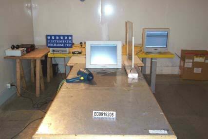

49 ELECTROSTATIC DISCHARGE TEST Page 49 Rev. 00

50 RADIATED ELECTROMAGNETIC FIELD TEST Page 50 Rev. 00

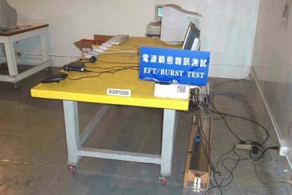
51 FAST TRANSIENTS/BURST TEST Page 51 Rev. 00

52 SURGE IMMUNITY TEST Page 52 Rev. 00

53 CONDUCTED DISTURBANCE, INDUCED BY RADIO-FREQUENCY FIELDS TEST Page 53 Rev. 00


54 POWER FREQUENCY MAGNETIC FIELD IMMUNITY TEST VOLTAGE DIPS / INTERRUPTION TEST Page 54 Rev. 00
55 APPENDIX II TEST RESULT OF EN / EN TEST REPORT 2003/9/16 01:29 PM Unit: Panel PC Model No.: PPC-153M Remarks: Temp: 25 o C Humid: 41% Operator: Arno Hsieh =========================================== TEST SETUP Test Freq.: Hz. Test Voltage: vac Waveform : SINE Test Time: 2.5 min. Classification : CLASS A Test Type: STEADY-STATE Prog. Zo Enabled: YES Prog. Zo: Motor Driven with Phase Angle Control: NO Impedance selected: DIRECT Synthetic R+L Enabled: NO Resistance: Ohms Inductance: uh MAX WATTS: 65.2W Page 55 Rev. 00
56 TEST DATA Result: PASS Harmonic Current Results Hn AMPS LO Limit HI Limit Result PASS NaN NaN PASS PASS PASS PASS PASS PASS PASS PASS PASS PASS PASS PASS PASS PASS PASS PASS PASS PASS PASS PASS Page 56 Rev. 00
57 PASS PASS PASS PASS PASS PASS PASS PASS PASS PASS PASS PASS PASS PASS PASS PASS PASS PASS PASS PASS END OF REPORT Page 57 Rev. 00
C-Tick EMC TEST REPORT. For. AC/DC Switching Power Supply
 C-Tick EMC TEST REPORT For AC/DC Switching Power Supply Model: CP0515(5V/1.5A); CP0520(5V/2A); CP0530 (5V/3A); CP0540 (5V/4A); CP0550 (5V/5A); CP0560 (5V/6A);CP0615(6V/1.5A); CP0620(6V/2A); CP0625 (6V/2.5A);
FCC 47 CFR PART 15 SUBPART B TEST REPORT. For. External USB 2.0 HDD Enclosure
 FCC 47 CFR PART 15 SUBPART B TEST REPORT For External USB 2.0 HDD Enclosure Model: AV300, AV500, LD300; AP35USL; EN318UHCR; EMV18BK; EMV18SL; EMV25BK; EMV25SL; EMV35BK; EMV35DBK; EMV35DSL; EMV35SL; ENAP25C;
CE EMC TEST REPORT. For IPC. Model: ACP Trade Name: ADVANTECH. Issued for
 CE EMC TEST REPORT For IPC Model: ACP-2320 Trade Name: ADVANTECH Issued for Advantech Co., Ltd. No. 1, Alley 20, Lane 26, Rueiguang Road, Neihu District, Taipei 114, Taiwan, R.O.C. Issued by Compliance
FCC 47 CFR PART 15 SUBPART B
 FCC 47 CFR PART 15 SUBPART B TEST REPORT For DC TO DC CONVERTER Model : D100 Series Issued for MicroPower Direct, LLC 232 Tosca Drive Stoughton, MA02072 U.S.A. Issued by Compliance Certification Services
CE EMC TEST REPORT. For. ATX Power Supply Tester. Model: POWER JUDGE ; TEST-ALIM-ATX-20/24 ; PSTESTER-1. Trade Name: Connectland ; POWMAX.
 CE EMC TEST REPORT For ATX Power Supply Tester Model: POWER JUDGE ; TEST-ALIM-ATX-20/24 ; PSTESTER-1 Trade Name: Connectland ; POWMAX Issued for COMING DATA CO., LTD. 5F-1, NO. 13, WU CHUNG 1RD, HSIN CHUNG
FCC CLASS B COMPLIANCE REPORT (DoC)
") FCC CLASS B COMPLIANCE REPORT (DoC) for Electromagnetic Emissions Of ENTRY LEVEL IP PHONE Trade Name : XONTEL Model Number : XT-19P Serial Number : N/A Report Number : PZD1611741-F Date : Regulations :
FCC CLASS B COMPLIANCE REPORT (DoC) for Electromagnetic Emissions Of ENTRY LEVEL IP PHONE Trade Name : XONTEL Model Number : XT-19P Serial Number : N/A Report Number : PZD1611741-F Date : Regulations :
FCC 47 CFR PART 15 SUBPART B TEST REPORT
 FCC 47 CFR PART 15 SUBPART B TEST REPORT for 19 Multimedia LCD Monitor MODEL: R19LXXX-IPXXXX (X=A~Z, a~z, 0 ~9, Blank or Slash) Test Report Number: 90406001-D Issued for Winmate Communication INC. 9F,
FCC 47 CFR PART 15 SUBPART B TEST REPORT
 FCC 47 CFR PART 15 SUBPART B TEST REPORT for 10.4 Rugged Tablet PC Model: R10V28M-VMXXXX (X=A~Z, a~z, 0 ~9, Blank or Slash) Test Report Number: 80808002-D Issued for Winmate Communication INC. 9F, No.
EMC COMPLIANCE TEST REPORT
 EMC COMPLIANCE TEST REPORT for IP PHONE Trade Name : XONTEL Model Number : XT-30G Serial Number : N/A Report Number : PZD1612757-E Date : Regulations : See below Standards EN 50561-1:2013+AC:2015; EN 61000-3-2:
ETSI EN V1.2.1: 2002 TEST REPORT. For. Bluetooth USB Hub. Model: MS Trade Name: MSI. Issued to
 ETSI EN 301 489-17 V1.2.1: 2002 TEST REPORT For Bluetooth USB Hub Model: MS-6871 Trade Name: MSI Issued to MICRO-STAR INT'L CO., LTD. NO. 69, Li-De St, Jung-He City, Taipei Hsien, Taiwan, R.O.C. Issued
ELECTRONICS TESTING CENTER(ETC), TAIWAN
, TAIWAN") File No. : 06-03-RBF-111-01 EMC TESTING DEPARTMENT II Page: 1 / 35 TEST REPORT Responsible Party Manufacturer Description of Product Trade Name : Huan Vu Enterprise Co., Ltd. : Huan Vu Enterprise Co.,
File No. : 06-03-RBF-111-01 EMC TESTING DEPARTMENT II Page: 1 / 35 TEST REPORT Responsible Party Manufacturer Description of Product Trade Name : Huan Vu Enterprise Co., Ltd. : Huan Vu Enterprise Co.,
CERTIFICATE. Issued Date: Apr. 20, 2006 Report No.: 064L079-IT-US-P01V01
 CERTIFICATE Issued Date: Apr. 20, 2006 Report No.: 064L079-IT-US-P01V01 This is to certify that the following designated product Product : 19 inch Rack-mounted Data Acquisition Computer Trade name : Moxa
No. 620 HuaYuan Commercial Center, No. 347 XiXiang Road,XiXiang Town, Bao An District, ShenZhen City Tel : Fax:
 No. 620 HuaYuan Commercial Center, No. 347 XiXiang Road,XiXiang Town, Bao An District, ShenZhen City Tel : +86-755-27912080 Fax: +86-755-27916936 FCC TEST REPORT Product name : 7PORT DUAL SUPPLY POE SWITCH
EMC TEST REPORT For MPP SOLAR INC Inverter/ Charger Model Number : PIP 4048HS
 EMC-E20130903E EMC TEST REPORT For MPP SOLAR INC Inverter/ Charger Model Number : PIP 4048HS Prepared for : MPP SOLAR INC Address : 4F, NO. 50-1, SECTION 1, HSIN-SHENG S. RD. TAIPEI, TAIWAN Prepared by
Harmonic Current emission EN :2014 Class A Pass. Voltage Fluctuation and Flicker EN :2013 Clause 5 Pass
 Reference No.: WTS15F0323845E Page 2 of 33 1 Test Summary Test Item Mains Terminal Disturbance Voltage, 148.5kHz to 30MHz Disturbance Power, 30MHz to 300MHz Discontinuous Disturbance (Click) Radiated Emission,
EMC TEST REPORT. For. Switching Mode Power Adaptor. Model No.: 9W/14.4V/EU(18V/1.0A), 19W/14.4V/EU(12V/1.5A)
, 19W/14.4V/EU(12V/1.5A)") EMC TEST REPORT For Company Limited Liability «Faraday Electronics» Switching Mode Power Adaptor Model No.: 9W/14.4V/EU(18V/1.0A), 19W/14.4V/EU(12V/1.5A) Prepared For : Company Limited Liability «Faraday
EMC TEST REPORT For Company Limited Liability «Faraday Electronics» Switching Mode Power Adaptor Model No.: 9W/14.4V/EU(18V/1.0A), 19W/14.4V/EU(12V/1.5A) Prepared For : Company Limited Liability «Faraday
Discontinuous Disturbance (Click) EN :2006+A1:2009+A2:2011 Clause N/A** Radiated Emission, 30MHz to 1000MHz
 EN :2006+A1:2009+A2:2011 Clause N/A** Radiated Emission, 30MHz to 1000MHz") Reference No.: WTN13F0706038E Page 2 of 40 1 Test Summary Test Item Mains Terminal Disturbance Voltage, 148.5kHz to 30MHz Disturbance Power, 30MHz to 300MHz EMISSION Test Standard Class / Severity Result
Reference No.: WTN13F0706038E Page 2 of 40 1 Test Summary Test Item Mains Terminal Disturbance Voltage, 148.5kHz to 30MHz Disturbance Power, 30MHz to 300MHz EMISSION Test Standard Class / Severity Result
FCC Verification TEST REPORT
 FCC Verification TEST REPORT Product: 5 in 1 Environment Meter Model no.: ET-965 Trade Mark: N/A Report No.: TCT140915E005 Issued Date: Sep. 22, 2014 Issued for: Shenzhen Flus Technology Co., Ltd 3rd Floor,
Test Report. Product Name: Cable Modem Model No.: BEFCMU10 ver.3 FCC ID. : Q87-BEFCMU10V3
 Report No. 036H064FI Test Report Product Name: Cable Modem Model No.: BEFCMU10 ver.3 FCC ID. : Q87-BEFCMU10V3 Applicant : Cisco-Linksys, LLC Address : 17401 Armstrong Avenue, Irvine, CA 92614 USA Date
EMC TEST REPORT. Report No.: CE10-LIE040101E
 EMC TEST REPORT Report No.: CE10-LIE040101E Product: LED TUBE Model No.: T10, T8, T5 Applicant: Shenzhen Saiju Electronic Co., Ltd. Address: 2nd. Xianshun Industrial Park, Gushu, Xixiang, Bao an, Shenzhen,
CE EMC TEST REPORT. for. IPC Model: IPC-619S; IPC-619XXXXXXXXXXXX; SYS-4U619X-XXXXXXXXXX (X = 0-9, A-Z or Blank) Test Report Number: E
 Test Report Number: E") CE EMC TEST REPORT for IPC Model: IPC-619S; IPC-619XXXXXXXXXXXX; SYS-4U619X-XXXXXXXXXX (X = 0-9, A-Z or Blank) Test Report Number: 90921102-E Issued for Advantech Co. Ltd. No.1, Alley 20, Lane 26, Rueiguang
CE EMC TEST REPORT for IPC Model: IPC-619S; IPC-619XXXXXXXXXXXX; SYS-4U619X-XXXXXXXXXX (X = 0-9, A-Z or Blank) Test Report Number: 90921102-E Issued for Advantech Co. Ltd. No.1, Alley 20, Lane 26, Rueiguang
TEST SUMMARY. Prüfbericht - Nr.: Test Report No.: Seite 2 von 27. Page 2 of 27
 15072768 001 Seite 2 von 27 Page 2 of 27 TEST SUMMARY 4.1.1 HARMONICS ON AC MAINS 4.1.2 VOLTAGE CHANGES, VOLTAGE FLUCTUATIONS AND FLICKER ON AC MAINS 4.1.3 MAINS TERMINAL CONTINUOUS DISTURBANCE VOLTAGE
CE EMC Test Certification
 Certification No.: EC57C001 CE EMC Test Certification According to European Standard EN 55022:1998/A1:2000/A2:2003 Class A, EN 61000-3-2: 2000, EN 61000-3-3:1995/A1:2001 and EN 55024:1998/A1:2001/A2:2003
Page: 1 of 20 EMC TEST REPORT EN55024:1998+A2:2003
 Page: 1 of 20 EMC TEST REPORT Reference No. Applicant : WT05060412 : Gembird Electronics Ltd. Equipment Under Test (EUT) : Product Name : Cable Standards Model No : UAS111-M, UAS111, UAS112 : EN55022:1998+A2:2003
TEST REPORT. Table of Contents
 Page:2 of 24 Table of Contents 1. DOCUMENT POLICY AND TEST STATEMENT... 3 1.1 DOCUMENT POLICY...3 1.2 TEST STATEMENT...3 2. DESCRIPTION OF EUT AND TEST MODE... 4 2.1 GENERAL DESCRIPTION OF EUT...4 2.2
TEST SUMMARY. Prüfbericht - Nr.: Test Report No.: Seite 2 von 25. Page 2 of 25
 15072259 001 Seite 2 von 25 Page 2 of 25 TEST SUMMARY 4.1.1 HARMONICS ON AC MAINS 4.1.2 VOLTAGE FLUCTUATIONS ON AC MAINS 4.1.3 MAINS TERMINAL CONTINUOUS DISTURBANCE VOLTAGE 4.1.4 DISCONTINUOUS INTERFERENCE
Shenzhen Toby Technology Co., Ltd. EMC Test Report. Report No.: TB-EMC Page: 1 of 20
 Shenzhen Toby Technology Co., Ltd. Report No.: TB-EMC125641 Page: 1 of 20 EMC Test Report Application No. : TB12114299 Applicant : Newmb Technology Co., Ltd. Equipment Under Test (EUT) EUT Name : USB HUB
EMC Test Report. Report Number: M030826
 Page 1 of 36 EMC Technologies Pty Ltd ABN 82 057 105 549 57 Assembly Drive Tullamarine Victoria Australia 3043 Ph: + 613 9335 3333 Fax: + 613 9338 9260 email: melb@emctech.com.au EMC Test Report Report
Test Report. Product Name: Wireless 11g USB Adapter Model No. : MS-6826, UB54G FCC ID. : DoC
 Test Report Product Name: Wireless 11g USB Adapter Model No. : MS-6826, UB54G FCC ID. : DoC Applicant : MICRO-STAR INT L Co., LTD Address : No 69, Li-De st., Jung-He City, Taipei Hsien, Taiwan, R.O.C Date
2620 Modular Measurement and Control System
 European Union (EU) Council Directive 89/336/EEC Electromagnetic Compatibility (EMC) Test Report 2620 Modular Measurement and Control System Sensoray March 31, 2006 April 4, 2006 Tests Conducted by: ElectroMagnetic
EN 55015: 2013 Clause Pass. EN 55015: 2013 Clause Pass. EN 55015: 2013 Clause Pass
 Reference No.: WTD15S0730643E Page 2 of 42 1 Test Summary Test Item Conducted Disturbance at Mains Terminal, 9kHz to 30MHz Radiation electromagnetic disturbance, 9kHz to 30MHz Radiation Emission, 30MHz
TABLE OF CONTENTS Page 1 of VERIFICATION OF CONFORMITY SYSTEM DESCRIPTION PRODUCT INFORMATION SUPPORT EQUIPMENT
 ELECTROMAGNETIC COMPLIANCE TEST REPORT For Electric nail art drill Model Name: HBS-021, HBS-278, HBS-288, HBS-530, HBS-540 Brand Name: Date of Issue: May 7, 2011 Prepared For Houbos Hardware & Electrical
TABLE OF CONTENTS 1. GENERAL DESCRIPTION OF EUT 3 2. GENERAL INFORMATION OF TEST CONDUCTED EMISSION TEST RADIATED EMISSION TEST 11
 Page : 2 / 38 TABLE OF CONTENTS 1. GENERAL DESCRIPTION OF EUT 3 2. GENERAL INFORMATION OF TEST 4 3.1 CONDUCTED EMISSION TEST 7 3.2 RADIATED EMISSION TEST 11 3.3 ELECTROSTATIC DISCHARGE IMMUNITY TEST 14
Certificate of Test AND KEEPS ALL REQUIREMENTS ACCORDING THE FOLLOWING REGULATIONS IEC :2001 IEC :2007
 Certificate of Test WE HEREBY CERTIFY THAT: Certificate No.: R07122709E Yuan Hsun Electric Co., Ltd. No. 57, Chung He Rd, Zuo-Ying Dist., Kaohsiung City 813, Taiwan R.O.C. Quad photobeam detector Quad-200CS
CERTIFICATE. Issued Date: Apr. 02, 2009 Report No.: R-ITUSP01V01
 CERTIFICATE Issued Date: Apr. 02, 2009 Report No.: 093337R-ITUSP01V01 This is to certify that the following designated product Product : 2G 8/16PORT Serial Device Server Trade name : Moxa Model Number
T A B L E O F C O N T E N T S DESCRIPTION PAGE
 TABLE OF CONTENTS DESCRIPTION PAGE 1. CERTIFICATION... 3 2. SUMMARY OF TEST RESULTS... 4 3. GENERAL INFORMATION... 5 3.1 PRODUCTION DESCRIPTION... 5 3.2 TEST MODES & EUT COMPONENTS DESCRIPTION... 5 3.3
EN 55022: 2010+AC:2011 Clause 6.1 Pass. Harmonic Current EN :2006+A1:2009+A2:2009 Class A N/A
 Reference No.: WT12106773-N-S-E Page 2 of 33 1 Test Summary Test Item Mains Terminal Disturbance Voltage, 150KHz to 30MHz Radiation Emission, 30MHz to 1000MHz EMISSION Test Standard Class / Severity Result
TEST REPORT... 1 CONTENT...
 CONTENT TEST REPORT... 1 CONTENT... 2 1 TEST RESULTS SUMMARY... 3 2 EMC RESULTS CONCLUSION... 4 3 LABORATORY MEASUREMENTS... 6 4 EMI TEST... 7 4.1 CONTINUOUS CONDUCTED DISTURBANCE VOLTAGE TEST... 7 4.2
EMC Testing Report. Dual-120CS. Yuan Hsun Electric Co., Ltd.
 EMC Testing Report Equipment Under Test: Model Number: Serial No.: Applicant: Address of Applicant: Multi-Frequency (4 Channel Selectable) Twin Photobeam Detector Dual-120CS Dual-90CS, Dual-60CS, Dual-30CS
EMC TEST REPORT. Report No.: TS EME Model No.: 33XR-A Issued Date: Jan. 08, 2009
 Page 1 of 18 EMC TEST REPORT Report No.: TS08100063-EME Model No.: 33XR-A Issued Date: Jan. 08, 2009 Applicant: Test Method/ Standard: Test By: FLUKE CORP. 6920 Seaway Blvd, M/S 266D Everett, WA 98203
VCCI TEST REPORT. for. Communication Appliance
 VCCI TEST REPORT for Communication Appliance MODEL: ODS-VL2-8; ODS-VL2-8-2AC; ODS-VL2-8-DC; ODS-VL2-8-2DC; ODS-VL2-XL-8; ODS-VL2-XL-8-2A; ODS-VL2-XL-8-DC; ODS-VL2-XL-8-2D; ODS-VL2-16; ODS-VL2-16-2AC; ODS-VL2-16-DC;
TEST REPORT. Table of Contents
 Page:2 of 35 Table of Contents 1. DOCUMENT POLICY AND TEST STATEMENT... 4 1.1 DOCUMENT POLICY...4 1.2 TEST STATEMENT...4 1.3 EUT MODIFICATION...4 2. DESCRIPTION OF EUT AND TEST MODE... 5 2.1 GENERAL DESCRIPTION
FCC Part 15 Subpart B
 Report No.: 15A111603E-F Page 1 of 23 Test Report FCC Part 15 Subpart B for Electromagnetic Interference of Product: Managed PoE Industrial Ethernet Switch Trade Name: N/A Model Number: IS-DG512P-2F-8;
EMC TEST REPORT For. Shenzhen Ruideou Keji Youxian Gongsi. Shenzhen Ruideou Keji Youxian Gongsi
 EMC TEST REPORT For Shenzhen Ruideou Keji Youxian Gongsi Product Name: Trademark: Milligram Scale WAOAW Model Number: W-01-50 Prepared For : Address: Prepared By : Address: Shenzhen Ruideou Keji Youxian
TEST REPORT. Issued for:
 TEST REPORT FCC ID: 2ACJAPLT76XXG Product: TABLET PC Model No.: PLT7650G, PLT7649G, PLT76XXG ( XX can be replaced by digital from 00 to 99 ) Trade mark: N/A Report No.: TCT150721E012 Issued Date: Aug.
VERIFICATION OF COMPLIANCE
 VERIFICATION OF COMPLIANCE This Verification of Compliance is hereby issued to the product designated below. Product Model Trade name Applicant Patient Infotainment Terminal/ Computer PIT-1502W; PIT-15XXXXXXXXXXXXXXXX;
CE EMC TEST REPORT. for. 8.4 G-WIN Rugged Panel PC MODEL: R08A83X-VMXXXX (X=A~Z, a~z, 0~9, Blank or Slash) Test Report Number: E.
 Test Report Number: E.") CE EMC TEST REPORT for 8.4 G-WIN Rugged Panel PC MODEL: R08A83X-VMXXXX (X=A~Z, a~z, 0~9, Blank or Slash) Test Report Number: 80625001-E Issued for Winmate Communication INC. 9F, No. 111-6, Shing-De Rd.,
CE EMC TEST REPORT for 8.4 G-WIN Rugged Panel PC MODEL: R08A83X-VMXXXX (X=A~Z, a~z, 0~9, Blank or Slash) Test Report Number: 80625001-E Issued for Winmate Communication INC. 9F, No. 111-6, Shing-De Rd.,
EN :2007+A1:2011 Electromagnetic compatibility Emission standard for residential, commercial and light-industrial environments
 EMC Page 3 / 33 Test report No.: EN 61000-6-3:2007+A1:2011 Electromagnetic compatibility Emission standard for residential, commercial and light-industrial environments Date of measurement: 2013-10-16
TEST REPORT. Report No. : EM/2008/80003 Page : 1 of 54
 Equipment Under Test Brand Name Model No. Added Model(s) Applicant Address of Applicant Page : 1 of 54 TEST REPORT : AC Servo Motor : Kingservo : AC 400W servo motor : N/A : Ho Fo Automation CO., LTD :
CE TEST CERTIFICATION
 according to Certification No.: E5NC004 European Standard EN 61000-6-4:2001 EN 61000-3-2: 2000, EN 61000-3-3:1995/A1:2001 and EN 61000-6-2:2001 ( IEC 61000-4-2:1995/A1:1998, IEC 61000-4-3: 1995/A1:1998,
EMC Testing Report. StarCam Genie N/A MICRO-STAR INT L CO., LTD.
 EMC Testing Report Equipment Under Test MSI StarCam Genie Model Number Serial No. Applicant Address of Applicant StarCam Genie N/A MICRO-STAR INT L CO., LTD. No.69, Lide St., Jhonghe City, Taipei County
CE EMC Test Report GUANGZHOU DMKEMOTOR CO. LTD
 CE REPORT CE EMC Test Report Equipment under Test: Model /Type: Applicant: Address: Manufacturer: Address: Laboratory: Address: Report Number Brush D.C. Motor D5D120-24GU D2D10-12GN, D2D10-24GN, D2D10-36GN,
EMC VERIFICATION SUMMARY Report No.: SZHH
 EMC VERIFICATION SUMMARY Toy ITE Others Additional Models: 0801 to 0899 INCLUSIVE, 0804, 0804W, 0805, 0806, 0807, 0808, 0809, 0811, 0811W, 0812, 0813, 0814,0815, 0816, 0817,0817 ROOM 619, 6/F. PENINSULA
Test Report. Product Name : IPC Model No.
 Test Report Product Name : IPC Model No. : On Demand Switch 3 (RODS3-DEFAULT) On Demand Switch 3 (RODS3-S1-DEFAULT) On Demand Switch 3 (RODS3-S2-DEFAULT) Applicant : Radware Ltd. Address : 22 Raoul Wallenberg
EMC TEST REPORT. according to
 EMC TEST REPORT according to European Standard EN 55022:2006/A1:2007 Class B, EN 61000-3-2:2006, EN 61000-3-3:1995/A1:2001/A2:2006, EN 55024:1998/A1:2001/A2:2003 (IEC 61000-4-2:Edition 1.2:2001-04, IEC
Test Report. Product Name : Access Point Model No.: MS-6809 FCC ID.: I4L-MS6809
 Test Report Product Name : Access Point Model No.: MS-6809 FCC ID.: I4L-MS6809 Applicant : MICRO-STAR INT L Co., LTD Address : No 69, Li-De st., Jung-He City, Taipei Hsien, Taiwan, R.O.C Date of Receipt
FCC & RSS-216 (Class II Permissive Change) Wireless Power Transfer Report. for A Acer Incorporated
 Wireless Power Transfer Report. for A Acer Incorporated") Page 1 of 17 FCC 15.209 & RSS-216 (Class II Permissive Change) Wireless Power Transfer Report for A Acer Incorporated 8F., No.88, Sec. 1, Xintai 5th Rd., Xizhi, New Taipei City 22181, Taiwan (R.O.C) Product
Page 1 of 17 FCC 15.209 & RSS-216 (Class II Permissive Change) Wireless Power Transfer Report for A Acer Incorporated 8F., No.88, Sec. 1, Xintai 5th Rd., Xizhi, New Taipei City 22181, Taiwan (R.O.C) Product
EMC REPORT. ShenZhen KY Technology Co.,Ltd. No.369, BaoTian 1st RD, TieGang Industrial Park, Xixiang Town, Baoan District, ShenZhen, PRC.
 Report No.: UNI2016121702ER-01 Page 1 / 30 ShenZhen KY Technology Co.,Ltd EMC REPORT Prepared For: ShenZhen KY Technology Co.,Ltd Product Name: Smart bracelet No.369, BaoTian 1st RD, TieGang Industrial
Test Report. Product Name : b P3 Wireless LAN PCMCIA Card Model No. : WN-110 FCC ID : QDWWN110
 Test Report Product Name : 802.11b P3 Wireless LAN PCMCIA Card Model No. : WN-110 FCC ID : QDWWN110 Applicant : AirVast Technology Inc. Address : 4F-1, No. 1, Ln. 21, Hsin Hua Rd., Kueishan Industrial
EMC COMPLIANCE TEST REPORT
 EMC COMPLIANCE TEST REPORT Technical Statement of Conformity in accordance with the council directive 2004/108/EC The product Equipment Under Test Model Number Product Series Report Number Issue Date Test
Overview of EMC Regulations and Testing. Prof. Tzong-Lin Wu Department of Electrical Engineering National Taiwan University
 Overview of EMC Regulations and Testing Prof. Tzong-Lin Wu Department of Electrical Engineering National Taiwan University What is EMC Electro-Magnetic Compatibility ( 電磁相容 ) EMC EMI (Interference) Conducted
MIL STD 461F TEST REPORT. For. Rugged PDA. Model Number: P37B. Trade Name: N/A. Issued to
 MIL STD 461F TEST REPORT For Rugged PDA Model Number: P37B Trade Name: N/A Issued to ACA Digital Corporation 17F.,No 866-7, Zhongzheng Rd, Zhonghe City, Taipei County, 235, Taiwan, R,O,C Issued by Compliance
for Issued for Supremevalue Technology CO., Ltd 4/F,A4 Bldg.,Yinlong Industrial Park,292# Shenshan Rd,518116, Longgang District,Shenzhen,China.
 EMC TEST REPORT for Product: Car Charger Trade Mark: MEKNIC Model: SV-PC01,SV-PC02,SV-PC03,SV-PC04,SV-PC05, SV-PC06,SV-PC07,SV-PC08,SV-PC09,SV-PC10, SV-PC11,SV-PC12,SV-PC13,SV-PC14,SV-PC15, SV-PC16,SV-PC17,SV-PC18,SV-PC19,SV-PC20
FCC DOC TEST REPORT. According to. 47 CFR, Part 2, Part 15, CISPR PUB. 22, ICES 003 Issue 6
 FCC DOC TEST REPORT According to 47 CFR, Part 2, Part 15, CISPR PUB. 22, ICES 003 Issue 6 Applicant Address Equipment Model No. Trade Name : Panasonic India Pvt. Ltd. : 6th Floor, "SPIC BUILDING" Annexe,
EN v3.1.1 TEST REPORT FOR. Bluetooth Serial Port Module MODEL NUMBER: LMX9838 REPORT NUMBER: 14U17620-E1V3 ISSUE DATE: AUGUST 31, 2017
 EN 301 489-17 v3.1.1 TEST REPORT FOR Bluetooth Serial Port Module MODEL NUMBER: LMX9838 REPORT NUMBER: 14U17620-E1V3 ISSUE DATE: AUGUST 31, 2017 Prepared for Texas Instrument 2900 Semiconductor Drive Santa
ITUNER NETWORKS CORPORATION EMC REPORT Fremont Blvd. Fremont, CA
 Shenzhen BST Technology Co., Ltd. ITUNER NETWORKS CORPORATION EMC REPORT Prepared For : ITUNER NETWORKS CORPORATION 47801 Fremont Blvd. Fremont, CA. 94538 Product Name: PicoPSU-150 Trade Name: PicoPSU
Prepared for Address. : KST DIGITAL TECHNOLOGY LIMITED : No.226, Pangu Street, Meixian, Meizhou, Guangdong. Prepared by
 EMC TEST REPORT For KST DIGITAL TECHNOLOGY LIMITED Coreless Servo Model No.: X12-508 Additional Model No.: DS215MG, DS315MG, DS213MG, DS313MG, DS12C, DS12T, X12-306 Prepared for Address : KST DIGITAL TECHNOLOGY
C E R T I F I C A T I O N
 C E R T I F I C A T I O N Applicant Address Manufacturer Address : American Power Conversion Holding Inc. Taiwan Branch : 3F., No. 205, Sec. 3, Beixin Rd., Xindian Dist., New Taipei City 231, Taiwan R.O.C.
CE TEST CERTIFICATION
 Certification No.: E5DC001 according to European Standard EN 61000-6-4:2001 EN 61000-3-2: 2000, EN 61000-3-3:1995/A1:2001 and EN 61000-6-2:2001 ( IEC 61000-4-2:1995/A1:1998, IEC 61000-4-3: 1995/A1:1998,
EMC TEST REPORT. Report No. : EM/2004/10096 Page : 1 of 19
 EMC TEST REPORT Page : 1 of 19 Equipment Under Test Model No. Applicant Address of Applicant : Bluetooth Headset : FB-HS01 : Formosa Teletek Corporation : 358, Huaya 2 nd Rd., Gueishan shiang, Taoyuan,
Test Report. : 09A255R-ITCEP28V01 Report Version : V1.0
 Established 1981 Advanced Test Equipment Rentals www.atecorp.com 800-404-ATEC (2832) Test Report Product Name : Industrial IEEE 802.11a/b/g dual-rf Access Point/Bridge/Client Model No. : AWK-6222-xx-y
EMC TEST REPORT. For. Boardcon Technology Limited. MINI9G45 Computer on Module. Model No. : MINI9G45
 REPORT NO. PRSZ15110502E EMC TEST REPORT For Boardcon Technology Limited. MINI9G45 Computer on Module Model No. : MINI9G45 Prepared For : Boardcon Technology Limited. : Room 702, Hua Feng Xin An Business
CONFORMANCE TEST REPORT FOR EN /-6
 CONFORMANCE TEST REPORT FOR EN 301489-1/-6 Client: Product: Model: Manufacturer/supplier: Aztech Systems Limited DECT Phone H315-S1 (FP) Aztech Systems Limited Date test item received: 2006/05/09 Date
C E R T I F I C A T I O N
 C E R T I F I C A T I O N Applicant Address Manufacturer Address : American Power Conversion Holding Inc. Taiwan Branch : 3F., No. 205, Sec. 3, Beixin Rd., Xindian Dist., New Taipei City 231, Taiwan R.O.C.
EMC TEST REPORT. NORTE SIRIUS ENTERPRISE CO., LTD , Shin-Sheng St., Chung-Ho Dist, New Taipei City, Taiwan
 Page 1 of 32 EMC TEST REPORT Report No.: TS11020117-EME Model No.: NS-PSE, NS-POINTED, NS-PSQUARE, NS-PF-S, NS-PT, NS-PR, NS-PU, NS-PF-H, NS-BALIBA, NS-FLEXMA Issued Date: Mar. 01, 2011 Applicant: NORTE
SUZHOU MAILI ELECTRICAL APPLIANCE CO., LTD NO.666,JIANLIN RD, XUGUAN SUBAREA, SUZHOU HIGH-TECH ZONE
 EMC TEST REPORT For SUZHOU MAILI ELECTRICAL APPLIANCE CO., LTD Product Name: Pure sine wave power inverter Trademark: Model : Prepared For : Address: Prepared By : Address: ML-1000W ML-300W---ML-8000W.
EMC TEST REPORT For INNOKIN TECHNOLOGY CO., LIMITED. ITaste vv. Model No.: ITaste vv
 EMC TEST REPORT For INNOKIN TECHNOLOGY CO., LIMITED ITaste vv Model No.: ITaste vv Prepared for : INNOKIN TECHNOLOGY CO., LIMITED Address : 3# Floor, #B Building, Heng Chang Rong Industrial Park, Gonghe
Test Report. Applicant ASUSTeK COMPUTER INC. 4F, No. 150, Li-Te Rd., Peitou, Taipei, Taiwan. Date of Receipt Jan. 28, Issued Date Mar.
 Test Report Product Name Model No. FCC ID. IC ID. WPC Qi 1.1/1.0 compliance wireless charging micro-usb box Wireless Charger MSQ-ASUSWLCHARGER 3568A-ASWLCHARGER Applicant ASUSTeK COMPUTER INC. Address
EMC Test Report FATEK AUTOMATION CORP. FATEK. FBs-TBOX N/A
 EMC Test Report Applicant: Address of Applicant: Trade Name: FATEK AUTOMATION CORP. 26FL, NO.29, SEC.2, JUNGJENG E. RD., DANSHUEI DIST., NEW TAIPEI CITY, TAIWAN, R.O.C. FATEK Equipment Under Test: Training
C E R T I F I C A T I O N
 C E R T I F I C A T I O N Applicant Address Manufacturer Address :American Power Conversion Holding Inc. Taiwan Branch :3F., No. 205, Sec. 3, Beixin Rd., Xindian Dist., New Taipei City 231, Taiwan R.O.C.
FCC Test Report. Report No.: AGC FE01 2AAP6UB15MSKB. Attestation of Global Compliance (Shenzhen) Co., Ltd
 Co., Ltd") Page 1 of 24 FCC Test Report Report No.: AGC03052141001FE01 FCC ID 2AAP6UB15MSKB PRODUCT DESIGNATION : Keyboard BRAND NAME : N/A MODEL NAME : UB-15MSKB CLIENT : Shenzhen Zowee Technology Co., Ltd. DATE
Page 1 of 24 FCC Test Report Report No.: AGC03052141001FE01 FCC ID 2AAP6UB15MSKB PRODUCT DESIGNATION : Keyboard BRAND NAME : N/A MODEL NAME : UB-15MSKB CLIENT : Shenzhen Zowee Technology Co., Ltd. DATE
FCC CLASS B COMPLIANCE REPORT (DOC)
") Page : 1 of 17 FCC CLASS B COMPLIANCE REPORT (DOC) Test Report No. : EM/2003/20077 Applicant/Factory : Moxa Technologies Co., Ltd. Address of Applicant : Fl. 4, No. 135, Lane 235, Pao-Chiao Rd., Shing
Page : 1 of 17 FCC CLASS B COMPLIANCE REPORT (DOC) Test Report No. : EM/2003/20077 Applicant/Factory : Moxa Technologies Co., Ltd. Address of Applicant : Fl. 4, No. 135, Lane 235, Pao-Chiao Rd., Shing
APPLICATION FOR EMC DIRECTIVE. On Behalf of. Shenzhen Qinhan Lighting Co., Ltd. led flood light. Trade Name:
 APPLICATION FOR EMC DIRECTIVE On Behalf of Shenzhen Qinhan Lighting Co., Ltd led flood light Trade Name: Model: QH-TGC-400W, QH-TGC-300W, QH-TGC-500W, QH-TGC-800W, QH-TGC-1000W Prepared For : Shenzhen
VCCI TEST REPORT. According to. Class B ITE. Equipment : USB video camera
 VCCI TEST REPORT According to Class B ITE Equipment : USB video camera Model No. : V-U0011 Applicant : Logitech Far East Ltd. 2 Creation Road IV, Science-Based Ind. Park, Hsinchu, Taiwan. The test result
Declaration of Conformity (DoC)
") Declaration of Conformity (DoC) Per 47 CFR 2.1077(a) & 15.19(a)(3) The following device is herewith confirmed to comply with Part 15 of the FCC Rules. Product Name : PCIE-USB380,PCIE-USB340 Model No. :
Declaration of Conformity (DoC) Per 47 CFR 2.1077(a) & 15.19(a)(3) The following device is herewith confirmed to comply with Part 15 of the FCC Rules. Product Name : PCIE-USB380,PCIE-USB340 Model No. :
MIL STD 461F TEST REPORT. For. Rugged PDA. Model Number: P37B. Trade Name: N/A. Issued to
 MIL STD 461F TEST REPORT For Rugged PDA Model Number: P37B Trade Name: N/A Issued to ACA Digital Corporation 17F.,No 866-7, Zhongzheng Rd, Zhonghe City, Taipei County, 235, Taiwan, R,O,C Issued by Compliance
Discontinuous Disturbance (Click) EN : 2011 Clause Pass Radiated Emission, 30MHz to 1000MHz
 EN : 2011 Clause Pass Radiated Emission, 30MHz to 1000MHz") Reference No.: WTU15U0933879E Page 2 of 45 1 Test Summary Test Item Mains Terminal Disturbance Voltage, 148.5kHz to 30MHz Disturbance Power, 30MHz to 300MHz EMISSION Test Standard Class / Severity Result
Reference No.: WTU15U0933879E Page 2 of 45 1 Test Summary Test Item Mains Terminal Disturbance Voltage, 148.5kHz to 30MHz Disturbance Power, 30MHz to 300MHz EMISSION Test Standard Class / Severity Result
TEST REPORT. Table of Contents
 Page:2 of 28 Table of Contents 1. DOCUMENT POLICY AND TEST STATEMENT... 3 1.1 DOCUMENT POLICY... 3 1.2 TEST STATEMENT... 3 2. DESCRIPTION OF EUT AND TEST MODE... 4 2.1 GENERAL DESCRIPTION OF EUT... 4 2.2
Test Report. Product Name : PC2PC-Bluetooth Model No. : MS Date of Receipt : Apr. 22, Date of Test : May 09, Report No.
 Report No. 024L064E Test Report Product Name : PC2PC-Bluetooth Model No. : MS-6967 Applicant : MICRO-STAR INT'L Co., LTD. Address : No. 69, Li-De St, Jung-He City, Taipei Hsien, Taiwan, R.O.C. Date of
EN v1.2.1 ( ) TEST REPORT FOR n 1X2 PCIe MINICARD TRANSCEIVER MODEL NUMBER: AR5B91 REPORT NUMBER: 08U
 TEST REPORT FOR n 1X2 PCIe MINICARD TRANSCEIVER MODEL NUMBER: AR5B91 REPORT NUMBER: 08U") EN 301 489-17 v1.2.1 (2002-08) TEST REPORT FOR 802.11n 1X2 PCIe MINICARD TRANSCEIVER MODEL NUMBER: AR5B91 REPORT NUMBER: 08U11615-3 ISSUE DATE: FEBRUARY 29, 2008 Prepared for ATHEROS COMMUNICATIONS, INC.
EN 301 489-17 v1.2.1 (2002-08) TEST REPORT FOR 802.11n 1X2 PCIe MINICARD TRANSCEIVER MODEL NUMBER: AR5B91 REPORT NUMBER: 08U11615-3 ISSUE DATE: FEBRUARY 29, 2008 Prepared for ATHEROS COMMUNICATIONS, INC.
FCC CFR47 PART 15 SUBPART C CERTIFICATION TEST REPORT FOR DUAL RADIO OUTDOOR ACCESS POINT MODEL NUMBER: AP-ONE FCC ID: SWX-AP1R2
 FCC CFR47 PART 15 SUBPART C CERTIFICATION TEST REPORT FOR DUAL RADIO OUTDOOR ACCESS POINT MODEL NUMBER: AP-ONE REPORT NUMBER: 04U3091-1 ISSUE DATE: JANUARY 07, 2005 Prepared for UBIQUITI NETWORKS 1111
CERTIFICATE. Issued Date: Aug. 20, 2009 Report No.: R-ITUSP02V01
 CERTIFICATE Issued Date: Aug. 20, 2009 Report No.: 095364R-ITUSP02V01 This is to certify that the following designated product Product : TCF-142-RM Series/Rack Chassis Trade name : Moxa Model Number :
Report for Excelsys EMC Measurements for 4Xgen Purchase Order: Project Number EMT07J026 Rev. B
 Report for Excelsys on EMC Measurements for 4Xgen Purchase Order: Project Number EMT07J026 Rev. B Rev Date Comment A April 2007 Change in DoC content B May 2007 Added Immunity Section EMT is a TÜV Appointed
EMC TEST REPORT. for. Coliy Technology Co.,Ltd. Fluxgate Gaussmeter
 Page 1 of 48 EMC TEST REPORT for Coliy Technology Co.,Ltd. Fluxgate Gaussmeter Prepared for : Coliy Technology Co.,Ltd. Address : Block B,9 th Floor,Xinzhongtai Business Building,Gushu 2nd Road,Xi Town,Bao
ELECTRONICS TESTING CENTER, TAIWAN
 File No.: 09-06-MAS-242-03 EMC TESTING DEPARTMENT Page:1/12 CONFORMANCE TEST REPORT FOR EN 301489-1 / -17 Report No.: 09-06-MAS-242-03 Client: Product: Model: Manufacturer/supplier: Ezurio Limited. Bluetooth
EMC TEST REPORT. ADDRESS : #2 Creation Rd. 4, Science-Based Ind. Park Hsinchu Taiwan, R.O.C.
 EMC TEST REPORT REPORT NO. : RM110613E07 MODEL NO. : M-R0027 RECEIVED : June 13, 2011 TESTED : June 17, 2011 ISSUED : June 22, 2011 APPLICANT : LOGITECH FAR EAST LTD. ADDRESS : #2 Creation Rd. 4, Science-Based
FCC DoC TEST REPORT. TESTED : Sep. 01 to 02, 2010 APPLICANT : LOGITECH FAR EAST LTD.
 FCC DoC TEST REPORT REPORT NO. : FD990901E04 MODEL NO. : Y-R0016 RECEIVED : Sep. 01, 2010 TESTED : Sep. 01 to 02, 2010 ISSUED DATE : Sep. 07, 2010 APPLICANT : LOGITECH FAR EAST LTD. ADDRESS : #2 Creation
Test Certificate A sample of the following product received on May 13, 2011 and tested on May 13, 18 and 19, 2011 complied with the requirements of,
 Test Certificate A sample of the following product received on May 13, 2011 and tested on May 13, 18 and 19, 2011 complied with the requirements of, EN 301 489-1 V1.8.1 Electromagnetic compatibility and
1 SUMMARY OF STANDARDS AND RESULTS
 1 SUMMARY OF STANDARDS AND RESULTS 1.1 Description of Standards and Results The EUT have been tested according to the applicable standards as referenced below: EMISSION Description of Test Item Standard
EMC TEST REPORT For ShenZhen ZhangQing Electronic LTD poe tester Model No.: WS POE Tester/Detector Additional Model No: Please Refer to Page 8
 EMC TEST REPORT For ShenZhen ZhangQing Electronic LTD poe tester Model No.: WS POE Tester/Detector Additional Model No: Please Refer to Page 8 Prepared for Address : ShenZhen ZhangQing Electronic LTD :