Project Name: SpyBot
|
|
|
- Raymond Shanon Johnston
- 6 years ago
- Views:
Transcription
1 EEL 4924 Electrical Engineering Design (Senior Design) Final Report April 23, 2013 Project Name: SpyBot Team Members: Name: Josh Kurland Name: Parker Karaus
2 TABLE OF CONTENTS Project Abstract...3 Introduction...4 Technical Objectives...5 Cost Objectives...10 Parts List...11 Division of Labor...13 TABLE OF FIGURES Block Diagram. 9 Gantt Chart. 14 Schematics. 15 PCB Layouts. 17 Software Flowcharts 19 2
3 Abstract Our project consists of a remote controlled vehicle equipped with a servo turret and mounted wireless camera. The vehicle is controlled remotely by a portable device using Xbee Wireless transceivers. Utilizing two joysticks the user can control the movement of the vehicle as well the camera direction. A large push button operates a laser that can be used to mark specific targets. The remote control also houses a Beagleboard-XM computer with an ARM8 processor. The Beagleboard takes the live video feed from the camera and implements a color tracking algorithm, which is then sent to a monitor through HDMI. 3
4 Introduction The SpyBot is used as a search and destroy device capable of tracking a subject (colored ball) from a distance. The purpose of this project was to build a remote controlled vehicle with a camera attached to a pan/tilt servo turret. The device will provide the user with a video feed in order to drive the vehicle and move the camera. The vehicle can be driven in close range within eyesight or over longer range through use of the video feed. The video displayed to the user has the option to track a colored target. The rover vehicle and camera can be driven or turned independently of one another. 4
5 Technical Objectives This project consisted of two distinct spheres of focus: Driving the vehicle and following an object. The vehicle uses DC motors driven by a microprocessor with H bridges in between. The H bridge takes the PWM pulse from the microprocessor and uses it as a signal to open and close the transistor gates and allow the voltage to flow to the motor. The wider the PWM pulse (the more area under the curve) the longer the gates will be opened, and the faster the motor will run. This also allows the motors to be controlled both forward and reverse. By using four control signals we can precisely control left and right steering. Sending a pulse to A and C will move the motors forward. A pulse on B and D will put the motors in reverse. Turning is achieved by sending signals to opposite directions. For example, 5
6 to turn left at an angle, C can be set to full speed while B will drive back at a fraction of its maximum, thus turning at precise angle. The vehicle and the remote control are both powered by 9.6V NiMH rechargeable batteries. To recharge the cells, we built a recharging circuit that provides a current source (from a 12V 500mA power pack) of about 200 ma. This slowly charges the battery packs until they reach their peak charge. Upon reaching their peak, the voltage curve will start to dip. To sense this voltage drop, a TL081 op amp was used as a comparator, with one input being the battery voltage by itself (in the negative input of the op amp), the other being the battery voltage along with a charging capacitor (in the positive input of the op amp). The capacitor will discharge slowly and still be greater than the pure battery voltage after the drop. This will result in a large increase in voltage from the output pin (from about 1-2 V to above 9 V). The op amp output is applied to the gate pin of a power PMOS transistor. When it receives a high voltage, there is not enough of a differential between source and gate to close the transistor, as the source end is receiving the voltage from the regulator. When the output is low (meaning the two compared voltages are near equal), the gate will have little voltage applied, meaning the source is being biased enough to create a large gate source differential, closing the transistor and allowing the batteries to charge. As the circuit must be closed to begin charging initially and obtain the voltage comparison, a switch is used to bridge the PMOS temporarily, after which it can be open to allow the PMOS and op amp to start or stop charging on their own. A large capacitor was used to ensure that the difference in peak voltage and dropped voltage would not be missed. Target color identification is achieved by using a thresholding algorithm. First the image is converted from RGB into an HSV color scale. Then the specific color s minimum and maximum HSV range values are set. This converts the video into a binary image, where all the pixels that fall outside of the threshold range are removed, leaving just the pixels of interest. The threshold 6
7 values can be set using a calibration algorithm that takes the average and standard deviation of all of the H, S, and V values. The maximum will be the average plus one standard deviation up to account for slightly brighter or duller values. The minimum will be the average minus the standard deviation. This will work as long as the entire frame is filled by the object. Any background color will affect the calibration. Target tracking is done by finding the spatial moment of the already thresholded binary image. The spatial moment of the image is the weighted average of the centroid over the area. ( ) ( ) ( ) ( ) This algorithm returns the first order moment of the colored object as it changes position in pixel space. This method is limited to tracking just one object at a time. If multiple objects of the same color are in the frame, the algorithm will attempt to detect the change in both objects. This will result in the moment being in the middle of both objects, instead identifying the correct position. Lastly, the processed video needed to be displayed to a screen. In the original proposal, we had not yet settled on what type of device we were going to use to process the video, so the specifics of the display output were not given. The Beagleboard was chosen due to its supported DVI-D output as well as special LCD expansion headers. It wasn t until later that it was discovered that the operating system chosen for its OpenCV support did not also include support to those expansion headers. The next option was to acquire an analog composite screen and use a digital to analog converter to output the video. After spending far longer than necessary modifying the kernel to support different screen resolutions, we learned that the 7
8 signal converter was in fact not compatible with the DVI-D video output used by the Beagleboard, so that the board would never get the digital handshake that it was expecting. Therefore the third choice was taken to use a standard computer monitor to view the camera video feed. While this method is not very portable, it is able to support far higher resolutions than the previous LCD designs could, resulting in a much better overall image. 8
9 Block Diagram 9
10 Cost Objectives Our initial goal was to spend less than $300 on this project, not including the cost of the computer and xbees. We ended up using the BeagleBoard as the computer for the image processing software, which cost a significant amount. The project still cost less than $500 overall, which was our absolute limit in purchasing, so our estimate was not too far off. According to the parts list below, which also includes spare parts and some unused parts, we spend a total of $ on all parts of the project. This includes the remote, rover, motor drivers, and PCBs (all of our PCBs were milled for free by UF or Advanced Circuits). Our project is similar to a handful of RC cars on the market with live video feeds. For example, the Spy Gear Spy Video Car VX-6 ( VX-6/dp/B004QM91JE/ref=sr_1_3?ie=UTF8&qid= &sr=8-3&keywords=rc+car+with+camera) is a remote controller car with LCD mounted in the controller. It costs far less than our project, mostly due to the lack of image processing of any sort, which we performed with the BeagleBoard. Our Spybot project is also able to turn the camera without turning the rover, since it is mounted on the pan/tilt servos rather than directly on the car. 10
11 Parts List SPYBOT Item Quantity Cost Shipping Total Remote Joystick 2 $3.95 $2.00 $7.90 Xbee NiMH Battery Pack 1 $16.00 $10.00 $26.00 Switch 3 $0.00 $0.00 $0.00 9V to 5V Regulator 1 $0.00 $0.00 $0.00 5V to 3.3V Regulator 1 $0.00 $0.00 $0.00 Large Push Button 1 $0.00 $0.00 $0.00 Enclosure 1 $8.00 $0.00 $8.00 MicroController 1 $0.00 $0.00 $0.00 Computer BeagleBoard 1 $ $0.00 $ HDMI - DVI Connector 1 $2.00 $0.00 $2.00 Computer Monitor Rover Rover-5 Platform 1 $27.00 $25.13 $52.13 IP Camera 1 $49.99 $0.00 $49.99 Xbee NiMH Battery Pack 1 $16.00 $10.00 $26.00 Processor 1 $0.00 $0.00 $0.00 Pan/Tilt Bracket 1 $5.95 $0.00 $5.95 Pan/Tilt Servo 2 $8.95 $0.00 $17.90 Low Power Laser 1 $7.95 $0.00 $7.95 Proximity Sensor 1 $13.95 $4.43 $18.38 Voltage Regulator 3 $0.00 $0.00 $0.00 Barrel Jack 1 $3.88 $0.00 $3.88 Recharge Circuit Op Amp 1 $0.00 $0.00 $0.00 Resistor 1 $0.00 $0.00 $0.00 Capacitor 3 $0.00 $0.00 $0.00 Switch 1 $0.00 $0.00 $0.00 Potentiometer 1 $0.00 $0.00 $0.00 Transistor 1 $0.20 $0.00 $0.20 Voltage Regulator 1 $0.00 $0.00 $0.00 Diode 3 $0.00 $0.00 $
12 H Bridges NPN MOSFET 20 $0.77 $0.00 $15.40 *includes spares/extras PNP MOSFET 10 $0.91 $0.00 $9.10 *includes spares/extras Resistor 12 $0.00 $0.00 $0.00 Opto-Isolator 8 $0.00 $0.00 $0.00 TOTAL $
13 Division of Labor Parker Karaus was responsible for H Bridge design and construction Battery Recharging circuit design and construction Xbee transceiver communication Josh Kurland was responsible for Beagleboard kernel, Operating System and OpenCV installation Image processing and tracking Camera setup and interface Shared tasks consist of PCB design Motor/servo drive code Parts selection 13
14 Gantt Chart Project Selection P+J Joystick Testing Xbee Communication P+J MicroProcessor PWM J DC Motor Interfacing P IP Camera Interacing P+J LCD Driver J Testing P+J Time 14

15 Schematics Rover: Recharge/Regulator: 15

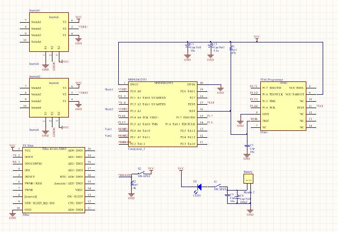
16 H-Bridge: Remote: 16

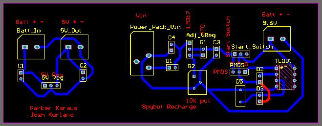
17 PCB Layouts Rover: Recharge/Regulator: 17

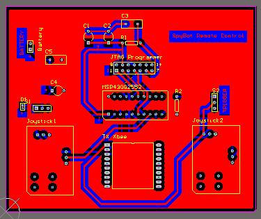
18 H-Bridge: Remote: 18
19 Software Flowcharts Rover: 19
20 Remote: 20
Electronic Components
 Electronic Components Arduino Uno Arduino Uno is a microcontroller (a simple computer), it has no way to interact. Building circuits and interface is necessary. Battery Snap Battery Snap is used to connect
Boozer Cruiser. EEL Electrical Engineering Design 2 Final Design Report. April 23, The Mobile Bartending Robot.
 EEL4924 - Electrical Engineering Design 2 Final Design Report April 23, 2013 Boozer Cruiser The Mobile Bartending Robot Team Members: Mackenzie Banker Perry Fowlkes mbanker@ufl.edu perry.pfowlkes@gmail.com
EEL4914 Senior Design. Final Design Report
 EEL4914 Senior Design Final Design Report Electric Super Bike The Best Team in the World Matt Fisher madfish@ufl.edu Richard Orr gautama@ufl.edu 21 April 2008 1 Contents Contents...2 Abstract...3 Project
Wireless Music Dock - WMD Portable Music System with Audio Effect Applications
 Wireless Music Dock - WMD Portable Music System with Audio Effect Applications Preliminary Design Report EEL 4924 Electrical Engineering Design (Senior Design) 26 January 2011 Members: Jeffrey Post and
M328 version ESR inductance capacitance meter multifunctional tester DIY
 M328 version ESR inductance capacitance meter multifunctional tester DIY About transistor Multifunction Tester: The tester uses 3.7V rechargeable lithium battery (battery model: 14500) powered portable
Final Design Report. Project Title: Multi-Function Pontoon (MFP)
") EEL 4924 Electrical Engineering Design (Senior Design) Final Design Report 25 April 2012 Project Title: Multi-Function Pontoon (MFP) Team Members: Name: Mikkel Gabbadon Name: Sheng-Po Fang Project Abstract:
EEL 4924 Electrical Engineering Design (Senior Design) Final Design Report 25 April 2012 Project Title: Multi-Function Pontoon (MFP) Team Members: Name: Mikkel Gabbadon Name: Sheng-Po Fang Project Abstract:
Built-in soft-start feature. Up-Slope and Down-Slope. Power-Up safe start feature. Motor will only start if pulse of 1.5ms is detected.
 Thank You for purchasing our TRI-Mode programmable DC Motor Controller. Our DC Motor Controller is the most flexible controller you will find. It is user-programmable and covers most applications. This
Lock Cracker S. Lust, E. Skjel, R. LeBlanc, C. Kim
 Lock Cracker S. Lust, E. Skjel, R. LeBlanc, C. Kim Abstract - This project utilized Eleven Engineering s XInC2 development board to control several peripheral devices to open a standard 40 digit combination
A Solar-Powered Wireless Data Acquisition Network
 A Solar-Powered Wireless Data Acquisition Network E90: Senior Design Project Proposal Authors: Brian Park Simeon Realov Advisor: Prof. Erik Cheever Abstract We are proposing to design and implement a solar-powered
STARTER / GENERATOR MOTOR CONTROLLER
 MIL-PRF-38534 AND 38535 CERTIFIED FACILITY M.S.KENNEDY CORP. STARTER / GENERATOR MOTOR CONTROLLER 4413 (315) 701-6751 FEATURES: 28V/160A Brushless DC motor control capability. 28V/90A Synchronous Boost
ECE 511: FINAL PROJECT REPORT GROUP 7 MSP430 TANK
 ECE 511: FINAL PROJECT REPORT GROUP 7 MSP430 TANK Team Members: Andrew Blanford Matthew Drummond Krishnaveni Das Dheeraj Reddy 1 Abstract: The goal of the project was to build an interactive and mobile
Wednesday 7 June 2017 Afternoon Time allowed: 1 hour 30 minutes
 Please write clearly in block capitals. Centre number Candidate number Surname Forename(s) Candidate signature A-level ELECTRONICS Unit 4 Programmable Control Systems Wednesday 7 June 2017 Afternoon Time
High Current DC Motor Driver Manual
 High Current DC Motor Driver Manual 1.0 INTRODUCTION AND OVERVIEW This driver is one of the latest smart series motor drivers designed to drive medium to high power brushed DC motor with current capacity
Ocean Controls KT-5198 Dual Bidirectional DC Motor Speed Controller
 Ocean Controls KT-5198 Dual Bidirectional DC Motor Speed Controller Microcontroller Based Controls 2 DC Motors 0-5V Analog, 1-2mS pulse or Serial Inputs for Motor Speed 10KHz, 1.25KHz or 156Hz selectable
Autonomous Robot Control Circuit
 Autonomous Robot Control Circuit - Theory of Operation - Written by: Colin Mantay Revision 1.07-06-04 Copyright 2004 by Colin Mantay No part of this document may be copied, reproduced, stored electronically,
Enhanced SmartDrive40 MDS40B
 Enhanced SmartDrive40 MDS40B User's Manual Rev 1.0 December 2015 Created by Cytron Technologies Sdn. Bhd. All Rights Reserved 1 INDEX 1. Introduction 3 2. Packing List 4 3. Product Specifications 5 4.
o What happens if S1 and S2 or S3 and S4 are closed simultaneously? o Perform Motor Control, H-Bridges LAB 2 H-Bridges with SPST Switches
 Cornerstone Electronics Technology and Robotics II H-Bridges and Electronic Motor Control 4 Hour Class Administration: o Prayer o Debriefing Botball competition Four States of a DC Motor with Terminals
Introduction to Electronics and Breadboarding Circuits
 Introduction to Electronics and Breadboarding Circuits What we're going to learn today: What is an electronic circuit? What kind of power is needed for these projects? What are the fundamental principles
RBS RADIO BATTERY SWITCH CONSTRUCTION MANUAL. RBS Construction Manual Issue 1 Page 1
 RBS RADIO BATTERY SWITCH CONSTRUCTION MANUAL RBS Construction Manual Issue 1 Page 1 CONTENTS 1 Introduction... 4 1.1 RBS features... 4 2 Batteries... 5 3 RBS specifications... 6 4 Circuit Description...
Final Report. Chazer Gator. by Siddharth Garg
 Final Report Chazer Gator by Siddharth Garg EEL 5666: Intelligent Machines Design Laboratory A. Antonio Arroyo, PhD Eric M. Schwartz, PhD Thomas Vermeer, Mike Pridgen No table of contents entries found.
roject work presentation
 roject work presentation roject Title: roject Index: 122 Microcontroller based power controller for an Electric Vehicle. y: Eric Bulimo Ubaga F17/1451/2011 upervisor: xaminer: Mr. C. Ombura. Dr. Dharma.
1 Second Time Base From Crystal Oscillator
 1 Second Time Base From Crystal Oscillator The schematic below illustrates dividing a crystal oscillator signal by the crystal frequency to obtain an accurate (0.01%) 1 second time base. Two cascaded 12
Massachusetts Institute of Technology MIT
 Massachusetts Institute of Technology MIT Real Time Wireless Electrocardiogram (ECG) Monitoring System Introductory Analog Electronics Laboratory Guilherme K. Kolotelo, Rogers G. Reichert Cambridge, MA
Preliminary Design Report. Project Title: Search and Destroy
 EEL 494 Electrical Engineering Design (Senior Design) Preliminary Design Report 9 April 0 Project Title: Search and Destroy Team Member: Name: Robert Bethea Email: bbethea88@ufl.edu Project Abstract Name:
4.2.2 Metal Oxide Semiconductor Field Effect Transistor (MOSFET)
") 4.2.2 Metal Oxide Semiconductor Field Effect Transistor (MOSFET) The Metal Oxide Semitonductor Field Effect Transistor (MOSFET) has two modes of operation, the depletion mode, and the enhancement mode.
4.2.2 Metal Oxide Semiconductor Field Effect Transistor (MOSFET) The Metal Oxide Semitonductor Field Effect Transistor (MOSFET) has two modes of operation, the depletion mode, and the enhancement mode.
RB-Rop-08 Scorpion XXL Dual 20A 6V to 28V R/C DC Motor Driver
 RB-Rop-08 Scorpion XXL Dual 20A 6V to 28V R/C DC Motor Driver The Robot Power Scorpion XXL is a flexible high-performance two-channel motor controller for small to medium mobile robots such as firefighting
Discrete Op-Amp Kit MitchElectronics 2019
 Discrete Op-Amp Kit MitchElectronics 2019 www.mitchelectronics.co.uk CONTENTS Introduction 3 Schematic 4 How It Works 5 Materials 9 Construction 10 Important Information 11 Page 2 INTRODUCTION Even if
DLVP A OPERATOR S MANUAL
 DLVP-50-300-3000A OPERATOR S MANUAL DYNALOAD DIVISION 36 NEWBURGH RD. HACKETTSTOWN, NJ 07840 PHONE (908) 850-5088 FAX (908) 908-0679 TABLE OF CONTENTS INTRODUCTION...3 SPECIFICATIONS...5 MODE SELECTOR
AD557 SPECIFICATIONS. T A = 25 C, V CC = 5 V unless otherwise noted) REV. B
 REV. B") SPECIFICATIONS Model Min Typ Max Unit RESOLUTION 8 Bits RELATIVE ACCURACY 0 C to 70 C ± 1/2 1 LSB Ranges 0 to 2.56 V Current Source 5 ma Sink Internal Passive Pull-Down to Ground 2 SETTLING TIME 3 0.8
SPECIFICATIONS Model Min Typ Max Unit RESOLUTION 8 Bits RELATIVE ACCURACY 0 C to 70 C ± 1/2 1 LSB Ranges 0 to 2.56 V Current Source 5 ma Sink Internal Passive Pull-Down to Ground 2 SETTLING TIME 3 0.8
Handy dandy little circuit #17 #17
 Handy dandy little circuit #17 #17 Download # 17 in PDF There are a lot of alarm systems on the market but you might be inclined to build your own. This little project can be put together using inexpensive
Experiment (1) Principles of Switching
 Principles of Switching") Experiment (1) Principles of Switching Introduction When you use microcontrollers, sometimes you need to control devices that requires more electrical current than a microcontroller can supply; for this,
Experiment (1) Principles of Switching Introduction When you use microcontrollers, sometimes you need to control devices that requires more electrical current than a microcontroller can supply; for this,
Robot Rangers. Low Level Design Document. Ben Andersen Jennifer Berry Graham Boechler Andrew Setter
 Robot Rangers Low Level Design Document Ben Andersen Jennifer Berry Graham Boechler Andrew Setter 2/17/2011 1 Table of Contents Introduction 3 Problem Statement and Proposed Solution 3 System Description
Adafruit 16-channel PWM/Servo Shield
 Adafruit 16-channel PWM/Servo Shield Created by lady ada Last updated on 2018-08-22 03:36:11 PM UTC Guide Contents Guide Contents Overview Assembly Shield Connections Pins Used Connecting other I2C devices
MD03-50Volt 20Amp H Bridge Motor Drive
 MD03-50Volt 20Amp H Bridge Motor Drive Overview The MD03 is a medium power motor driver, designed to supply power beyond that of any of the low power single chip H-Bridges that exist. Main features are
Preliminary Design Report. Project Title: Mutli-Function Pontoon (MFP)
") EEL 4924 Electrical Engineering Design (Senior Design) Preliminary Design Report 31 January 2011 Project Title: Mutli-Function Pontoon (MFP) Team Members: Name: Mikkel Gabbadon Name: Sheng-Po Fang Project
EEL 4924 Electrical Engineering Design (Senior Design) Preliminary Design Report 31 January 2011 Project Title: Mutli-Function Pontoon (MFP) Team Members: Name: Mikkel Gabbadon Name: Sheng-Po Fang Project
DC motor control using arduino
 DC motor control using arduino 1) Introduction: First we need to differentiate between DC motor and DC generator and where we can use it in this experiment. What is the main different between the DC-motor,
Robotic Navigation Distance Control Platform
 Robotic Navigation Distance Control Platform System Block Diagram Student: Scott Sendra Project Advisors: Dr. Schertz Dr. Malinowski Date: November 18, 2003 Objective The objective of the Robotic Navigation
Multi-Stage Power Conversion Proposal
 Multi-Stage Power Conversion Proposal Joe Driscoll, Paul Hemberger, David Yamnitsky Introduction MSPC is a three stage power converter system where each stage not only supports a useful application, but
CHAPTER 7 HARDWARE IMPLEMENTATION
 168 CHAPTER 7 HARDWARE IMPLEMENTATION 7.1 OVERVIEW In the previous chapters discussed about the design and simulation of Discrete controller for ZVS Buck, Interleaved Boost, Buck-Boost, Double Frequency
Hobby Servo Tutorial. Introduction. Sparkfun: https://learn.sparkfun.com/tutorials/hobby-servo-tutorial
 Hobby Servo Tutorial Sparkfun: https://learn.sparkfun.com/tutorials/hobby-servo-tutorial Introduction Servo motors are an easy way to add motion to your electronics projects. Originally used in remotecontrolled
I. INTRODUCTION MAIN BLOCKS OF ROBOT
 Stair-Climbing Robot for Rescue Applications Prof. Pragati.D.Pawar 1, Prof. Ragini.D.Patmase 2, Mr. Swapnil.A.Kondekar 3, Mr. Nikhil.D.Andhare 4 1,2 Department of EXTC, 3,4 Final year EXTC, J.D.I.E.T Yavatmal,Maharashtra,
Autonomous Refrigerator. Vinícius Bazan Adam Jerozolim Luiz Jollembeck
 Autonomous Refrigerator Vinícius Bazan Adam Jerozolim Luiz Jollembeck Introduction Components Circuits Coding Marketing Conclusion Introduction Uses Specimen and Culture Refrigerators can be found in many
PCB & Circuit Designing (Summer Training Program) 6 Weeks/ 45 Days PRESENTED BY
 6 Weeks/ 45 Days PRESENTED BY") PCB & Circuit Designing (Summer Training Program) 6 Weeks/ 45 Days PRESENTED BY RoboSpecies Technologies Pvt. Ltd. Office: D-66, First Floor, Sector- 07, Noida, UP Contact us: Email: stp@robospecies.com
PCB & Circuit Designing (Summer Training Program) 6 Weeks/ 45 Days PRESENTED BY RoboSpecies Technologies Pvt. Ltd. Office: D-66, First Floor, Sector- 07, Noida, UP Contact us: Email: stp@robospecies.com
List of Items Available in the Laboratory the Lab
 List of Items Available in the Laboratory the Lab Category Component 555 Timer $0.30 5V Relay $3.50 74xxx Series IC Chip $0.30 Battery - 12V (rechargeable Lead-acid type) $16.00 Battery - 6V (rechargeable
PRELIMINARY DESIGN REPORT
 PRELIMINARY DESIGN REPORT Dodge This! DODGERS: Cristobal Rivero Derek Fairbanks 1/27/2009 Abstract: Our project is to develop an automatic dodge ball game. It consists of an infrared video camera, computer,
Bill of Materials: PWM Stepper Motor Driver PART NO
 PWM Stepper Motor Driver PART NO. 2183816 Control a stepper motor using this circuit and a servo PWM signal from an R/C controller, arduino, or microcontroller. Onboard circuitry limits winding current,
Temperature Monitoring and Fan Control with Platform Manager 2
 August 2013 Introduction Technical Note TN1278 The Platform Manager 2 is a fast-reacting, programmable logic based hardware management controller. Platform Manager 2 is an integrated solution combining
MTC-2 highlight features: ACU highlight features: Contents. MTC-2 and ACU User Manual V5.1
 MTC-2 can work alone as a twin motor ECS (electronic speed controller) for RC tanks. When the ACU (auxiliary control unit) is connected, it can also control turret rotation, gun elevation, gun firing,
Semiconductor 9/21/2015
 Semiconductor Electronics 9/21/2015 Starting simple the diode. The diode is one of the simplest semiconductor devices. It is comprised of two layers of semiconductor. One is impregnated with an electron
Temperature Monitoring and Fan Control with Platform Manager 2
 Temperature Monitoring and Fan Control September 2018 Technical Note FPGA-TN-02080 Introduction Platform Manager 2 devices are fast-reacting, programmable logic based hardware management controllers. Platform
ECE 477 Digital Systems Senior Design Project Rev 8/09. Homework 5: Theory of Operation and Hardware Design Narrative
 ECE 477 Digital Systems Senior Design Project Rev 8/09 Homework 5: Theory of Operation and Hardware Design Narrative Team Code Name: _ATV Group No. 3 Team Member Completing This Homework: Sebastian Hening
Marine Debris Cleaner Phase 1 Navigation
 Southeastern Louisiana University Marine Debris Cleaner Phase 1 Navigation Submitted as partial fulfillment for the senior design project By Ryan Fabre & Brock Dickinson ET 494 Advisor: Dr. Ahmad Fayed
PS2-SMC-06 Servo Motor Controller Interface
 PS2-SMC-06 Servo Motor Controller Interface PS2-SMC-06 Full Board Version PS2 (Playstation 2 Controller/ Dual Shock 2) Servo Motor Controller handles 6 servos. Connect 1 to 6 Servos to Servo Ports and
High Current MOSFET Toggle Switch with Debounced Push Button
 Set/Reset Flip Flop This is an example of a set/reset flip flop using discrete components. When power is applied, only one of the transistors will conduct causing the other to remain off. The conducting
6. HARDWARE PROTOTYPE AND EXPERIMENTAL RESULTS
 6. HARDWARE PROTOTYPE AND EXPERIMENTAL RESULTS Laboratory based hardware prototype is developed for the z-source inverter based conversion set up in line with control system designed, simulated and discussed
Project Name: Tail-Gator
 EEL 4924 Electrical Engineering Design (Senior Design) Final Report 22 April 2013 Project Name: Tail-Gator Team Name: Eye in the Sky Team Members: Name: Anthony Incardona Name: Fredrik Womack Page 2/14
Park Ranger. Li Yang April 21, 2014
 Park Ranger Li Yang April 21, 2014 University of Florida Department of Electrical and Computer Engineering EEL 5666C IMDL Written Report Instructors: A. Antonio Arroyo, Eric M. Schwartz TAs: Andy Gray,
The FMMT718 Range, Features and Applications
 The Range, Features and Applications Replacing SOT89, SOT223 and D-Pak Products with High Current SOT23 Bipolar Transistors. David Bradbury Neil Chadderton Designers of surface mount products wishing to
MTC-2 highlight features: ACU highlight features: Contents. MTC-2 and ACU User Manual V4.0
 MTC-2 can work alone as a twin motor ECS (electronic speed controller) for RC tanks. When the ACU (auxiliary control unit) is connected, it can also control turret rotation, gun elevation, gun firing,
Adafruit 16-channel PWM/Servo Shield
 Adafruit 16-channel PWM/Servo Shield Created by lady ada Last updated on 2017-06-29 07:25:45 PM UTC Guide Contents Guide Contents Overview Assembly Shield Connections Pins Used Connecting other I2C devices
Simple-H User Manual
 Simple-H User Manual Thank you for your purchase of the Robot Power Simple-H. This manual explains the features and functions of the Simple-H along with some tips for successful application. Before using
Industrial Automation Training Academy. Arduino, LabVIEW & PLC Training Programs Duration: 6 Months (180 ~ 240 Hours)
") nfi Industrial Automation Training Academy Presents Arduino, LabVIEW & PLC Training Programs Duration: 6 Months (180 ~ 240 Hours) For: Electronics & Communication Engineering Electrical Engineering Instrumentation
nfi Industrial Automation Training Academy Presents Arduino, LabVIEW & PLC Training Programs Duration: 6 Months (180 ~ 240 Hours) For: Electronics & Communication Engineering Electrical Engineering Instrumentation
MD04-24Volt 20Amp H Bridge Motor Drive
 MD04-24Volt 20Amp H Bridge Motor Drive Overview The MD04 is a medium power motor driver, designed to supply power beyond that of any of the low power single chip H-Bridges that exist. Main features are
Features and Applications of the FMMT617 and FMMT717 SuperSOT SOT23 Transistors 3A NPN and 2.5A PNP SOT23 Bipolar Devices
 Features and Applications of the and SuperSOT SOT23 Transistors 3A NPN and 2.5A PNP SOT23 Bipolar Devices David Bradbury Neil Chadderton Introduction The following note describes some of the features,
WELCOME TO THE SEMINAR ON INTRODUCTION TO ROBOTICS
 WELCOME TO THE SEMINAR ON INTRODUCTION TO ROBOTICS Introduction to ROBOTICS Get started with working with Electronic circuits. Helping in building a basic line follower Understanding more about sensors
Embedded Systems & Robotics (Winter Training Program) 6 Weeks/45 Days
 6 Weeks/45 Days") Embedded Systems & Robotics (Winter Training Program) 6 Weeks/45 Days PRESENTED BY RoboSpecies Technologies Pvt. Ltd. Office: W-53G, Sector-11, Noida-201301, U.P. Contact us: Email: stp@robospecies.com
Embedded Systems & Robotics (Winter Training Program) 6 Weeks/45 Days PRESENTED BY RoboSpecies Technologies Pvt. Ltd. Office: W-53G, Sector-11, Noida-201301, U.P. Contact us: Email: stp@robospecies.com
Hydra: A Three Stage Power Converter
 6.101 Project Proposal Paul Hemberger, Joe Driscoll, David Yamnitsky Hydra: A Three Stage Power Converter Introduction Hydra is a three stage power converter system where each stage not only supports a
*X036/12/01* X036/12/01 TECHNOLOGICAL STUDIES HIGHER NATIONAL QUALIFICATIONS 2015 TUESDAY 12 MAY 1.00 PM 4.00 PM
 X036/12/01 NATIONAL QUALIFICATIONS 2015 TUESDAY 12 MAY 1.00 PM.00 PM TECHNOLOGICAL STUDIES HIGHER 200 marks are allocated to this paper. Answer all questions in Section A (120 marks). Answer two questions
CEEN Bot Lab Design A SENIOR THESIS PROPOSAL
 CEEN Bot Lab Design by Deborah Duran (EENG) Kenneth Townsend (EENG) A SENIOR THESIS PROPOSAL Presented to the Faculty of The Computer and Electronics Engineering Department In Partial Fulfillment of Requirements
Jaguar Motor Controller (Stellaris Brushed DC Motor Control Module with CAN)
") Jaguar Motor Controller (Stellaris Brushed DC Motor Control Module with CAN) 217-3367 Ordering Information Product Number Description 217-3367 Stellaris Brushed DC Motor Control Module with CAN (217-3367)
Jaguar Motor Controller (Stellaris Brushed DC Motor Control Module with CAN) 217-3367 Ordering Information Product Number Description 217-3367 Stellaris Brushed DC Motor Control Module with CAN (217-3367)
Ocean Controls KT-5221 Modbus IO Module
 Ocean Controls Modbus IO Module 8 Relay Outputs 4 Opto-Isolated Inputs 2 Analog Inputs (10 bit) 1 PWM Output (10 bit) 4 Input Counters Connections via Pluggable Screw Terminals 0-5V or 0-20mA Analog Inputs,
Touchless Control: Hand Motion Triggered Light Timer
 Touchless Control: Hand Motion Triggered Light Timer 6.101 Final Project Report Justin Graves Spring 2018 1 Introduction Often times when you enter a new room you are troubled with finding the light switch
Adafruit 16-Channel PWM/Servo HAT & Bonnet for Raspberry Pi
 Adafruit 16-Channel PWM/Servo HAT & Bonnet for Raspberry Pi Created by lady ada Last updated on 2018-03-21 09:56:10 PM UTC Guide Contents Guide Contents Overview Powering Servos Powering Servos / PWM OR
Bi-Directional DC Motor Speed Controller 5-32Vdc (3166v2)
") General Guidelines for Electronic Kits and Assembled Modules Thank you for choosing one of our products. Please take some time to carefully read the important information below concerning use of this product.
General Guidelines for Electronic Kits and Assembled Modules Thank you for choosing one of our products. Please take some time to carefully read the important information below concerning use of this product.
DACPORT Low Cost, Complete P-Compatible 8-Bit DAC AD557*
 a FEATURES Complete 8-Bit DAC Voltage Output 0 V to 2.56 V Internal Precision Band-Gap Reference Single-Supply Operation: 5 V ( 10%) Full Microprocessor Interface Fast: 1 s Voltage Settling to 1/2 LSB
Viper 2x35 Operating Modes
 SP ROBOTIC WORKS PVT. LTD. Viper 2x35 Operating Modes Contents 1. Operating Modes... 2 1.1 Input Modes... 2 1.1.1 R/C Transmitter Mode... 2 1.1.2 Microcontroller Mode... 3 1.2 Motor Control Modes... 3
Fast IC Power Transistor with Thermal Protection
 Fast IC Power Transistor with Thermal Protection Introduction Overload protection is perhaps most necessary in power circuitry. This is shown by recent trends in power transistor technology. Safe-area,
Automotive Surge Suppression Devices Can Be Replaced with High Voltage IC
 Automotive Surge Suppression Devices Can Be Replaced with High Voltage IC By Bruce Haug, Senior Product Marketing Engineer, Linear Technology Background Truck, automotive and heavy equipment environments
2015 International Future Energy Challenge Topic B: Battery Energy Storage with an Inverter That Mimics Synchronous Generators. Qualification Report
 2015 International Future Energy Challenge Topic B: Battery Energy Storage with an Inverter That Mimics Synchronous Generators Qualification Report Team members: Sabahudin Lalic, David Hooper, Nerian Kulla,
T6+ Analog I/O Section. Installation booklet for part numbers: 5/4-80A-115 5/4-90A-115 5/4-80A /4-90A-1224
 T and T+ are trade names of Trol Systems Inc. TSI reserves the right to make changes to the information contained in this manual without notice. publication /4A115MAN- rev:1 2001 TSI All rights reserved
How to build a Cracklebox. Red Wierenga Brooklyn College Center for Computer Music October 13, 2015
 How to build a Cracklebox Red Wierenga Brooklyn College Center for Computer Music October 13, 2015 What s a Cracklebox? What s a Cracklebox? The Cracklebox was developed by Michel Waisvisz and others at
OpenAFM. Electronics
 OpenAFM Electronics Voice Coils Each coil is controlled by a pair of push-pull amplifiers. One of each pair has a constant output voltage of 2.5v The other member of the pair is controlled by the output
Electronics, Sensors, and Actuators
 Electronics, Sensors, and Actuators 4/14/15 David Flicker BE107 Overview Basic electronics and components Sensors Actuators Electronics 101 Voltage, V, is fundamentally how much energy is gained or lost
PreLab 6 PWM Design for H-bridge Driver (due Oct 23)
") GOAL PreLab 6 PWM Design for H-bridge Driver (due Oct 23) The overall goal of Lab6 is to demonstrate a DC motor controller that can adjust speed and direction. You will design the PWM waveform and digital
GOAL PreLab 6 PWM Design for H-bridge Driver (due Oct 23) The overall goal of Lab6 is to demonstrate a DC motor controller that can adjust speed and direction. You will design the PWM waveform and digital
Castle Creations, INC.
 Castle Link Live Communication Protocol Castle Creations, INC. 6-Feb-2012 Version 2.0 Subject to change at any time without notice or warning. Castle Link Live Communication Protocol - Page 1 1) Standard
ELEC1 (JUN13ELEC101) General Certificate of Education Advanced Subsidiary Examination June Introductory Electronics TOTAL. Time allowed 1 hour
 General Certificate of Education Advanced Subsidiary Examination June Introductory Electronics TOTAL. Time allowed 1 hour") Centre Number Surname Candidate Number For Examiner s Use Other Names Candidate Signature Examiner s Initials Question Mark General Certificate of Education Advanced Subsidiary Examination June 2013 1
Centre Number Surname Candidate Number For Examiner s Use Other Names Candidate Signature Examiner s Initials Question Mark General Certificate of Education Advanced Subsidiary Examination June 2013 1
User s Manual. ACPL-339J Isolated Gate Driver Evaluation Board. Quick-Start. Testing Either Arm of The Half Bridge Inverter Driver (without IGBT)
") ACPL-339J Isolated Gate Driver Evaluation Board User s Manual Quick-Start Visual inspection is needed to ensure that the evaluation board is received in good condition. The default connections of the evaluation
ACPL-339J Isolated Gate Driver Evaluation Board User s Manual Quick-Start Visual inspection is needed to ensure that the evaluation board is received in good condition. The default connections of the evaluation
Motors and Servos Part 2: DC Motors
 Motors and Servos Part 2: DC Motors Back to Motors After a brief excursion into serial communication last week, we are returning to DC motors this week. As you recall, we have already worked with servos
Miniature PCM Remote Control
 Miniature PCM Remote Control part : transmit at 4 MHz and 950 nm! Here s a design that should gladden the hearts of many model builders. A really small proportional remote control unit built using standard
PCB & Circuit Designing
 (Summer Training Program) 4 Weeks/30 Days PRESENTED BY RoboSpecies Technologies Pvt. Ltd. Office: W-53G, Sector-11, Noida-201301, U.P. Contact us: Email: stp@robospecies.com Website: www.robospecies.com
SELF-SUSTAINABLE SOLAR STREET LIGHT CHARGING
 SELF-SUSTAINABLE SOLAR STREET LIGHT CHARGING By Anirban Banerjee Priya Mehta Surya Teja Tadigadapa Final Report for ECE 445, Senior Design, Fall 2017 TA: Zipeng Wang December 2017 Project No. 4 Abstract
Programming PIC Microchips
 Programming PIC Microchips Fís Foghlaim Forbairt Programming the PIC microcontroller using Genie Programming Editor Workshop provided & facilitated by the PDST www.t4.ie Page 1 DC motor control: DC motors
Autonomous Visual Rover
 Autonomous Visual Rover Diante Reid, Sean Day, Liem Huynh School of Electrical Engineering and Computer Science, University of Central Florida, Orlando, Florida, 32816-2450 Abstract In this paper we present
PCB & Circuit Designing (Summer Training Program 2014)
") (Summer Training Program 2014) PRESENTED BY In association with RoboSpecies Technologies Pvt. Ltd. Office: A-90, Lower Ground Floor, Sec- 4, Noida, UP Contact us: Email: stp@robospecies.com Website: www.robospecies.com
(Summer Training Program 2014) PRESENTED BY In association with RoboSpecies Technologies Pvt. Ltd. Office: A-90, Lower Ground Floor, Sec- 4, Noida, UP Contact us: Email: stp@robospecies.com Website: www.robospecies.com
Solar Array Maximum Powerpoint Tracker
 Solar Array Maximum Powerpoint Tracker Michigan State University Senior Design Capstone ECE 480, Team 8 Fall 2014 Project Sponsor Michigan State University Solar Car Team Project Facilitator Bingseng Wang
Inside The imax B6 Balance Charger
 University of Canterbury Competitive Robotics (UCCR1) VEX Texas Instruments Electronics Online Challenge Jack Wilkie Table of Contents Introduction... 2 Disassembly... 2 Analysis... 4 Conclusion... 6 Jack
LDOR: Laser Directed Object Retrieving Robot. Final Report
 University of Florida Department of Electrical and Computer Engineering EEL 5666 Intelligent Machines Design Laboratory LDOR: Laser Directed Object Retrieving Robot Final Report 4/22/08 Mike Arms TA: Mike
The Transistor Tester user manual
 The Transistor Tester user manual Power: The Transistor Tester can be powered from 6.8V-12V DC. This can be achieved by a 9V layerbuilt battery or two 3.7V Lithium-ion battery in series, or with a 9V DC
Refer to the drawing on page 2 to familiarize yourself with the connectors and controls on the
 PT Boat Sound by CAUTION: This device can be damaged by static discharge. Please exercise care during installation to avoid this possibility. Discharge yourself to an electrical ground (outlet cover screw
Abu Dhabi Men s College, Electronics Department. Logic Families
 bu Dhabi Men s College, Electronics Department Logic Families There are several different families of logic gates. Each family has its capabilities and limitations, its advantages and disadvantages. The