Solid State Aircraft
|
|
|
- Julian Miller
- 6 years ago
- Views:
Transcription
1 Solid State Aircraft NIAC 6 th Annual Meeting October 19-20, 2004 Seattle, Washington Anthony Colozza Northland Scientific / Ohio Aerospace Institute Cleveland, Ohio

2 Solid State Aircraft Team Members Mr. Anthony Colozza (PI): Mr. Phillip Jenkins: Dr. Mohsen Shahinpoor Mr. Teryn Dalbello: Dr. Kakkattukuzhy Isaac Mr. Curtis Smith: Dr. David Olinger Andrew Day Lindsay Robbins NSI/OAI OAI Environmental Robotics Inc. University of Toledo/ICOMP University of Missouri-Rolla OAI Worcester Polytechnic Institute
 to produce an aircraft that has no moving parts, can fly at high altitudes, is easily deployable and has applications on Earth, Venus and")
3 Solid State Aircraft Artist Concept Drawing The aircraft concept is to integrate three unique types of materials (thin film solar arrays, thin film lithium batteries and an ionic polymer metal composite) to produce an aircraft that has no moving parts, can fly at high altitudes, is easily deployable and has applications on Earth, Venus and Mars
4 Aircraft Operation Thin Film Battery Cathode Grid IPMC Material Thin Film Array Anode Grid The aircraft operates by collecting and converting sun light to electricity through a thin film photovoltaic array. This electricity is then stored in a battery. At specified intervals the energy is discharge to the anode and cathode grids to set up an electric field about the IPMC (synthetic muscles )material This electric field causes the IPMC to move thereby causing a flapping motion of the wing. This flapping motion produces lift and thrust for the aircraft. The electric field generated by the grids is controllable, therefore the shape and motion of the wing is controllable on each flap.
.")
5 Thin Film Photovoltaic Array Light Weight: Active material is on the order of 1 to 2 microns thick Highly Flexible: Ideal for the flexing and motion of a flapping wing Substrate: Can be made of most materials, presently the best candidate is Kapton (or other polymers). Potentially the Battery or IPMC can be utilized as the substrate CdS/Cu2S CuInSe2 CuGaSe2 CuInS2 CdTe a-si CASCADES Specific Power: 1 kw/kg near term, 2 kw/kg projected

6 Thin Film Battery/Capacitor Characteristics ITNES sample battery Rechargeable, Lightweight and Flexible Configurable in any series / parallel combination Rapid charging / discharging capability Can be charged / discharged 1000s of times with little loss in capacity Enables long duration flight times Long shelf life with little self discharge Ideal for stowage during interplanetary transit Operate over a wide temperature range Enables the batteries to operate under various environmental conditions The batteries have the capability to provide high pulse currents Ideal for short duration power loading such as flapping the wings
7 Ionic Polymer-Metal Composite (IPMC) QuickTime and a YUV420 codec decompressor are needed to see this picture. This is the core material of the aircraft. It provides the propulsion and control for the vehicle. The IPMC material has the unique capability to deform when an electric field is present across it. The amount and force of the deformation is directly related to the strength of the electric field. The deformation is not permanent and returns to its original shape once the electric field is eliminated. The material can be manufactured in any size and initial or base shape.
8 IPMC Material Constructed of an Ion Exchange Membrane that is surface coated with a conductive medium such as Platinum Placement of the electrodes can be used to tailor the bending of the material to any shape Metal Electrodes Contact Electrode + PIEM - Pt Particles The material will bend toward the anode side of the electrodes Pt Electrode OFF PIEM PIEM + - ON
9 IPMC Motion Under an electric field the ion exchange membrane Enables the migration of ions which allows water molecules and Hydrated cations to migrate toward the negative pole. This internal movement of water molecules is responsible for creating Internal strains within the material which enable it to move For the IPMC material to operate it must be sufficiently Hydrated Leakage and operation in dry environments may require sealing or redesign of the material for efficient long term use + + side chain hydrated cation-na(h2o)4 + water fixed anion mobile cation


10 Potential Operational Environments The analysis is set up so that the environments of either Venus, Earth or Mars can be easily selected All the relevant environmental conditions are expressed in equation format for easy use in the analysis A single variable is used to select the planet of operation. All subsequent environmental information is changed to the selected planets environment,

11 Constants Mean Solar Intensity Orbital Eccentricity Day Length Maximum Declination Mean Orbital Radius Days in the Year Perihelion Day Number Mean Planet Radius Gravitational Force Environmental Properties Variables as Function of Altitude Solar Attenuation Atmospheric Density Atmospheric Temperature Atmospheric Viscosity Wind Velocity Variable as Function of Time of Year and Location Solar Elevation Angle


12 Venus Environment Rotation Period (Day) of Venus is Longer the Revolution Period (Year) Potentially Enabling Continuous Flight Earth Surface Atmosphere is mainly Carbon Dioxide (96.5%) Also contains trace amounts of corrosive Compounds (Hydrochloric, hydrofluoric & Sulfuric Acids) Atmospheric Density Equals Earth Surface Density at ~50 km Incident Solar Intensity is ~2600 W/m 2 Very high wind speeds above the cloud tops ~ 100 m/s Clouds On Venus Extend Upwards to ~64 km


13 80 km Ice Crystal Haze Venus Atmospheric Structure -93 C 70km Sulfuric Acid Cloud Deck Thin Smog -43 C 60km 50 km 40 km 30 km 20 km Slow Convection Circulation 10 to 50 km Atmosphere Convectively Stable, Global Circulation Patterns Horizontal With Rising Currents at the Equator Descending at the Poles Thick Opaque Clouds, High Sulfuric Acid Gloomy Red Murk Haze layer - Thin Likely Sulfuric Acid Particles Atmosphere is Clear Below 30 km -23 C 67 C 142 C 210 C 390 C 10 km 0 km Slow Convection Cells, Low Winds Surface 410 C 455 C

 The majority of Earth s weather occurs")
14 Earth Environment Gravitational Force 9.81 m/s 2 Solar Intensity 1352 W/m 2 Atmospheric composition is approximately 80% Nitrogen, 20% Oxygen Wind speeds generally increase from the surface up to a maximum around the top of the Troposphere (Jet Stream) The majority of Earth s weather occurs within the Troposphere which extends to approximately 12 km

15 Mars Environment The atmosphere on Mars is very thin. At the Surface the density is similar to 30 km on Earth The atmosphere is composed mostly of Carbon Dioxide The temperature on Mars is on average much colder then on Earth Although at certain times of the year and locations the temperature will rise above freezing, most of the time temperatures are well below the freezing point of water. The gravitational force on Mars (3.57 m/s 2 )is about 1/3 what it is on Earth. Solar intensity at Mars is ~590 W/m 2 There are few clouds but dust storms are fairly common
. Resistance to water evaporation from IPOC within arid environments. Low temperature operation.")
16 Environmental Considerations on the Structure The SSA must be capable of withstanding the environmental conditions at the various proposed operational locations. Resistance to corrosive atmospheric compounds (ex, sulfuric acid on Venus). Resistance to water evaporation from IPOC within arid environments. Low temperature operation. Erosive effects of dust (especially for Mars operation). The selection and evaluation of coatings to resist these environmental effects is under way

17 Nature Inspired Configuration Nature Has A Way Of Finding The Optimum Initial Chord distribution is based on the Pteranodon wing shape. Chord distribution will be optimized through CFD analysis for the design flight conditions of the SSA. The Pteranodon is the largest animal that ever flew. It is the closest in size, weight and wing span to the SSA As an initial starting point for a more detailed wing design the Pteranodon wing shape will be used as the model.
18 Baseline Aircraft Configuration Like all flapping wing flyers in nature (birds, bats) the solid state aircraft will have a low wing loading and operate within a low Reynolds number flight regime. ri Chord Length, c i Normalized Chord Distribution Station from Root to Tip Wing Section Length, R Wing geometry and motion are all variable that can be adjusted to provide optimum array output and flight performance

19 Material Integration: Near Term Goal: To produce a method for combining the solar array, battery and IPMC materials into a single flexible structure for lab testing. Off-the-Shelf components will be used as much as possible. The array & IPMC will be assembled using adhesives, lamination or other readily available means. The control grid will be constructed integral with the IPMC material. Potential adhesion methods will be tested on coupon samples of the thin film array, IPMC, wiring and electrodes. Due to the development stage of thin film batteries, these initial integration tests will only include the array and IPMC materials. External batteries or capacitors will be used during this initial testing. The various integration methods will be tested for adhesion and bending capability.
20 Electrode Placement & Operation This is one of the more critical & challenging tasks to be undertaken For efficient flight the wing must be capable of flapping, twisting & changing the camber of the airfoil along the wing length This is accomplished by the placement and operation of the electrodes that control the IPMC material motion Analysis of the electric field generation for various electrode placements Devise an electrode layout & associated voltage strength / polarity to achieve a given wing shape Devise a means of controlling electrode voltage from a single processor & power source Produce a wing test section to validate the electric field analysis & control scheme

 micron Force resolution down to 1 mg Efficiency")
21 IPMC Material Properties & Construction Two of the largest pieces of IPMC (~45 cm X 23 cm) ever made have been constructed to serve as test wing sections. Young's Modulus, E Up to 2 GPa Shear Modulus, G Up to 1 GPa Poisson's ratio, ν Typical: Power density (W/mass) Up to 100 J/kg Max force density (Cantilever Up to 40 Kgf/Kg Mode) Max displacement/strain Up to 4% linear strain Bandwidth (speed) Up to 1 khz in cantilever vibratory mode for actuations Up to 1 MHz for sensing Resolution (force and Displacement accuracy down to 1 displacement control) micron Force resolution down to 1 mg Efficiency (electromechanical) Up to 6 %(frequency dependent) for actuation Up to 90% for sensing Density Down to 0.8 g/cm 3 Material Efficiency

22 Long Term Integration Strategy Goal: To provide a scheme to producing a fully integrated composite structure from the three main materials and subsequent components. The potential of construction the SSA by depositing each component material layer onto the subsequent layer is being investigated. This method would use the IPMC material as the main substrate. The battery layer and solar cell layer as well as the electrodes and wiring would be build directly onto the IPMC through a combination of deposition and lithography techniques. Some of the main issues that are to be examined are the material compatibilities, adhesion characteristics, material thickness and deposition and lithography techniques, their capabilities and requirements.
23 Feasibility Analysis Approach Flight Environment (Ex. Altitude, Latitude) Available Power Power Required To Fly Aircraft Geometry (Ex. Aspect Ratio, Wing Area, Mass) Feasibility analysis is an iterative process between the power available and the power required to fly. The flight environment and aircraft geometry and properties factor into determining these quantities.
 Time of year (δ) Time of day (θ) Available power also depends on the Atmosphere attenuation (τ) Solar cell")
24 Power Production The amount of power available to the aircraft is based on the Environmental conditions it is flying within Output power will vary based on the Latitude of flight (φ) Time of year (δ) Time of day (θ) Available power also depends on the Atmosphere attenuation (τ) Solar cell efficiency (η)
25 Approximately 50,000 spreadsheet cells are used to calculate the array output The output power of the array is calculated by determining the power of a small segment of the array and integrating this over the length of the wing. This is performed throughout the flap motion.
26 Effect of Wing Angle and Attitude on Array Output Power Summer Solstice The analysis allows the SSA attitude to be varied. The SSA can be pointed in any direction (360 ) within the plane of flight. This will eventually enable the analysis to simulate a mission flight. The examples shown are for Earth It should be noted however, that the attitude of the aircraft did not have a significant effect on the output power for summertime month operation.
27 Effect of Wing Angle and Attitude on Array Output Power Winter Solstice The wing was curved in a parabolic shape. The wing curvature is also a variable in the analysis and effects both power output and lift generation.
28 Power Output Along the Wing June 21st, 0 Latitude 0 Attitude Power output along the wing is shown for different wing angles, times of the day, latitudes and aircraft attitude. This calculation of instantaneous output power is integrated and summed to provide the energy available throughout a flap cycle Wing Station Variation in output power along the wing is not significantly effected when that aircraft is at an attitude of 0
29 Power Output Along the Wing More significant effects on the output power along the wing are seen at attitudes of 90
30 Power Production Throughout A Flap Cycle Total energy available is the integrated area under the flap cycle power curve This energy is compared to the energy required to determine feasibility under the given flight conditions and aircraft geometry. The shorter the flap duration the greater the energy produced & however, the greater the power required Energy Available Energy Required Flap Duration Glide Duration Maximum Glide 12,658 J 12,658 J 3.3 s 10.6 s Minimum Glide 11,961 J 2,439 J 13.9 s 0 s

31 Power Consumption Motion of the Wing Communications Bending Twisting Induced Drag Parasite Drag Power required by internal systems & their inefficiencies Drag due to lift generation & movement through the air Payload Control Grid Avionics Computer System
32 Power Consumption due to Motion Motion of the wing consists of a flapping rate and maximum angle traversed during the flap The forces generated by the wing motion are due to the acceleration and deceleration of the wing mass. These forces vary along the wing length The force and therefore energy required to move a small segment of the wing is calculated. These are summed and multiplied by the efficiency of the IPMC in generating the required force. This integrated force calculation is performed over the flap cycle.
33 Wing Force Due to Motion Force versus Distance Traveled for Various Wing Lengths, Maximum Flap Angles and Flap Frequencies 10 The power required to move the wing is the area under the force vs distance traveled curve. Force (N) Length 1m, Angle 40, Cycle 1s Length 1m, Angle 40, Cycle 4s Length 1m, Angle 60, Cycle 1s Length 1m, Angle 60, Cycle 4s Length 3m, Angle 40, Cycle 1s Length 3m, Angle 40, Cycle 4s Length 3m, Angle 60, Cycle 1s Length 3m, Angle 60, Cycle 4s The distance traveled varies along the wing length to a maximum at the tip. The tapered planform minimizes the mass at the wing tip and therefore minimizes the force required to move the wing Distance Travled (m)
 and the specific masses of the components that make it up. Force Generated Thrust Lift Weight Payload mass (0.25 kg) Solar array specific mass (~0.")
34 Required Lift The required lift needed for the aircraft to fly will depend on the total mass of the aircraft. The wing mass is dependent on its shape (area) and the specific masses of the components that make it up. Force Generated Thrust Lift Weight Payload mass (0.25 kg) Solar array specific mass (~0.12 kg/m 2 ) IPMC material specific mass (~1.5 kg/m 2 ) Thin film battery specific mass (~ 0.25 kg/m 2 ) Operational systems (communications, flight computer, etc.) mass (0.5 kg)
35 Producing Enough Lift to Fly For a given airfoil & chord distribution, the lift produced by the wing is calculated throughout a flap cycle. This lift generation will be dependent on the various wing motion parameters The angle the wing traverses The rate at which the wing is moving The twist or change in angle of attack of the specific segment of the wing The lift produced by each segment of the wing throughout the flap motion is calculated and summed to get the total wing lift generated.
36 Determination of Lift & Thrust Generation The propulsion force and lift generation of the aircraft are accomplished by the flapping of the wings. By altering the shape and angle of attack of the wing the amount of lift and the direction of this lift force can be controlled This is the same method birds use to generate lift and thrust The lift and lift vector generated can Vary between each wing as well as along the wing span itself. This provides a significant amount of control and provides a means for maneuvering

37 Ongoing Aerodynamic Analysis & Design 2-D performance estimates will be generated under specific flight conditions using airfoil analysis tools (FLUENT, XFOIL, JavaFoil) SSA Analysis tool will be used to evaluate the performance of the SSA with various types of airfoils based on their 2D performance characteristics Using the 2D results an airfoil and wing distribution will be selected. Full 3D steady-state modeling of the wing will be done at fixed points thorughout the flapping motion. An evaluation of the tools and approach necessary to perform a full 3D analysis of the moving wing are being determined Airfoil Selection: Thin Airfoil with 1% thickness & 5% Camber Attributes: Good low Reynolds number characteristics Thin cross section minimizes mass Performance data is being generated at low Reynolds numbers (~100,000)


38 CFD Airfoil Analysis CFD analysis is ongoing to provide lift coefficient and drag coefficient data for a thin curved airfoil at Angles of attack and Reynolds numbers representative of the estimated SSA flight regime and wing motion Various Flat Plate Airfoils, Eppler 378 & Selig 1091 are being evaluated Curved Flat Plate Turbulence Velocity Field Selig 1091 Velocity Field Eppler 378

39 Aerodynamic & CFD Analysis Goals The aerodynamic analysis is to provide a performance estimate (lift & drag) of the SSA under various operational conditions. Through an iterative process this analysis will be used to determine the optimum wing geometry, motion and SSA performance capabilities. Ultimately the CFD analysis is to provide a full steady-state 3D flow field over the SSA using the optimized wing geometry and motion for discrete points throughout the flapping motion. Requirements and a plan for achieving a full transient 3D analysis are being assembled.
 The power needed for each individual wing segment to overcome this drag is equal")
40 Total drag is the summation of the parasite & induced drag or each of the individual segments along the wing. The Associated Drag Velocity due to Wing Motion Resultant Velocity D f = i 0 P i =D i V i 1 2 ρv 2 i (c f 2S + c d S) The power needed for each individual wing segment to overcome this drag is equal to the drag on that segment and the segments instantaneous velocity. Velocity of a segment of the wing. V fi = Free Stream Velocity V 2 + 4θr i t f
41 Overall Energy Balance The energy balance is performed over a complete flap cycle. The energy collected by the solar array must be equal to or greater then that needed by the vehicle to fly and power all its systems. Sufficient lift must be generated during the flapping portion of the cycle so that the aircraft can climb For a given wing geometry, motion and flight location, the flap duration / glide duration are iterated upon to produce a combination that enables the aircraft to fly. Or to produce a combination that minimizes energy consumption. Power Time
42 The energy consumed during the flap has to equal the energy collected during the total flap and glide cycle. Power Available Analysis Method Inputs Flapping Frequency Flap Angle Aircraft Size Altitude Lift Generated Flight Speed Flap to Glide Ratio Power Consumed (Motion & Drag) The analysis was an iterative process For a given set of inputs the flight speed and flap to glide ratio would be calculated. If no solution existed then certain inputs would be varied until a solution was found.
43 Analysis Progress and Objectives Using the analysis described results on the flight capabilities under Earth environmental conditions were produced These results were generated to validate the analysis method as well as investigate the aircraft performance sensitivity and flight envelope to variations in operational conditions and size. Effect of Latitude Effect of Altitude Effect of Flight Time of Year Effect of Aircraft Size Updated aerodynamic data will be incorporated into the analysis to provide more accurate results. The analysis tool will be utilized to optimize the aircraft geometry and wing motion. Results will be generated for Venus and Mars flight environments.
44 As latitude increases the available energy decreases. The energy required decreased with increasing flap duration, until the glide duration equals zero. Energy available increases as the cycle time (flap duration + glide duration) increases. The minimum power required occurs when the glide duration goes to zero. This is because the required flap duration time increases at a faster rate then the decrease in glide duration. Effect of Latitude For Flight on Earth at 15 km Altitude on March 21st with a 10m wingspan
45 Effect of Altitude For Flight on Earth at 45 N Latitude on March 21st with a 10m wingspan Energy required varies slightly with increasing altitude. As altitude increases the maximum flap duration decreases. Shorter more frequent flaps are needed to compensate for the lower density air. Energy available is reduced as altitude increases due to the shorter flap cycles Flap Duration (s)
46 Effect of Time of the Year For Flight on Earth at 45 N Latitude at 15 km Altitude with a 10m wingspan The available energy decreases in the winter months and increased during the summer due to seasonal effects.
47 Effect of Aircraft Size For Flight on Earth at 45 N Latitude, Altitude of 15 km on March 21st The aircraft scales with size by increasing the flap duration. Larger aircraft require more energy per flap but also produce much more energy. At a given altitude the larger the aircraft the larger the flap durations can be and therefore the more efficient the aircraft is Flap Duration (s)
48 Maximum Achievable Altitude For Flight on Earth at 45 N Latitude, Curves show flight at the maximum efficiency when the glide duration is zero. As the aircraft size increases the maximum altitude increases but this is a diminishing

49 Mission Analysis Utilizing the SSA capabilities established from the performance & communications analysis & vehicle design work, an evaluation of the potential mission the SSA may be capable of carrying out will be made. Critical factors will be flight duration, flight altitude, payload capacity, payload power availability& data transfer capability. From these various types of science data gathering & observing equipment will be assessed. The mission assessments will be performed for all three potential planets of operation. Both individual & multiple aircraft operations will be considered. For multiple aircraft missions, a fleet of SSAs can be considered which could either perform a unique task or provide an infrastructure such as a communications network. Specific aspects of the missions are also being considered these include: Stowage while in space transit (for Venus and Mars missions) Deployment Navigation Altitude Control Landing
50 Science & Payload Science & other equipment will be evaluated for use on the SSA. This evaluation will take into consideration the instruments mass, volume, power requirements and operational concerns such as vibration as well as the potential for miniaturization. Potential science & data gathering includes: Camera, high resolution and context Atmospheric measurements: temperature, pressure etc. Magnetic field measurements. Communications relay transmitter / receiver Atmospheric sounding with various frequencies (dependent on the capabilities of the communications system) Beacon In addition to specific payloads, the systems on board the SSA will be evaluated to determine if any dual use potential exists. For example the communications antenna may be used to send receive signals at various frequencies in order to collect data in a sounding fashion.
 can be imaged at various angles Imagery can be used for survalence, mapping or geological characterization of the planet.")
51 Science: High Resolution Imagery Detailed images can be taken on a regional scale at high resolution Vertical structures (canyon, mountain) can be imaged at various angles Imagery can be used for survalence, mapping or geological characterization of the planet.

52 Science: Atmospheric Sampling & Analysis Examine the Atmosphere Both Vertically & Horizontally (Temperature & Pressure) Sample Atmospheric Trace Gases Determine Concentrations of Trace Gases and Reactive Oxidizing Species Examine the Correlation with the Presence of Active Oxidizing Agents and Absence of Organics in Martina Soil Investigation of Dust within the Atmosphere and Dust Storms Sample Long Lived Airborne Dust in the Atmosphere (Size, Distribution, Electrostatic Charging etc.)

53 Science: Magnetic Field Mapping Mapping of the Magnetic Fields can Give Insight into the Tectonic History of the Planet & Investigate the Geology and Geophysics of Venus
54 Communications System Communications to satellite with transparent metallic antenna Communications or data collection through sounding to surface with thin film antenna Getting data & information to and from the SSA is a critical function. The unique configuration of the SSA & its thin light flexible structure pose a unique challenge for the communications system.
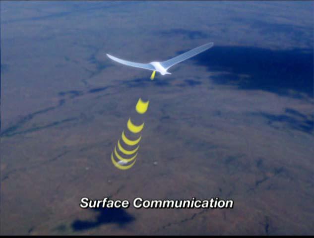


55 Quickly Deployable Observation / Communications Network

56 Solid State Aircraft Mission Animation
Venus Aircraft. design evolution Geoffrey A. Landis. NASA John Glenn Research Center. Geoffrey A. Landis.
 Venus Aircraft design evolution 2000-2008 Geoffrey A. Landis NASA John Glenn Research Center Geoffrey A. Landis Venus Aircraft Atmospheric exploration trade-study Balloon Simple technology Demonstrated
Rec. ITU-R P RECOMMENDATION ITU-R P *
 Rec. ITU-R P.682-1 1 RECOMMENDATION ITU-R P.682-1 * PROPAGATION DATA REQUIRED FOR THE DESIGN OF EARTH-SPACE AERONAUTICAL MOBILE TELECOMMUNICATION SYSTEMS (Question ITU-R 207/3) Rec. 682-1 (1990-1992) The
Space Weather and the Ionosphere
 Dynamic Positioning Conference October 17-18, 2000 Sensors Space Weather and the Ionosphere Grant Marshall Trimble Navigation, Inc. Note: Use the Page Down key to view this presentation correctly Space
A Hybrid Trailing Edge Control Surface Concept
 Pınar ARSLAN, Uğur KALKAN, Harun TIRAŞ, İlhan Ozan TUNÇÖZ, Yosheph YANG, Ercan GÜRSES, Melin ŞAHİN, Serkan ÖZGEN, Yavuz YAMAN Department of Aerospace Enginnering, Middle East Technical University Ankara,
Design of an Airborne SLAR Antenna at X-Band
 Design of an Airborne SLAR Antenna at X-Band Markus Limbach German Aerospace Center (DLR) Microwaves and Radar Institute Oberpfaffenhofen WFMN 2007, Markus Limbach, Folie 1 Overview Applications of SLAR
The Earth s Atmosphere
 ESS 7 Lectures 15 and 16 May 5 and 7, 2010 The Atmosphere and Ionosphere The Earth s Atmosphere The Earth s upper atmosphere is important for groundbased and satellite radio communication and navigation.
Analysis of Potential for Venus-Bound Cubesat Scientific Investigations
 Analysis of Potential for Venus-Bound Cubesat Scientific Investigations Image Sources: Earth Science and Remote Sensing Unit, NASA Johnson Space Center; JAXA / ISAS / DARTS / Damia Bouic / Elsevier inc.
ESS 7 Lectures 15 and 16 November 3 and 5, The Atmosphere and Ionosphere
 ESS 7 Lectures 15 and 16 November 3 and 5, 2008 The Atmosphere and Ionosphere The Earth s Atmosphere The Earth s upper atmosphere is important for groundbased and satellite radio communication and navigation.
Hyper-spectral, UHD imaging NANO-SAT formations or HAPS to detect, identify, geolocate and track; CBRN gases, fuel vapors and other substances
 Hyper-spectral, UHD imaging NANO-SAT formations or HAPS to detect, identify, geolocate and track; CBRN gases, fuel vapors and other substances Arnold Kravitz 8/3/2018 Patent Pending US/62544811 1 HSI and
High-speed wavefront control using MEMS micromirrors T. G. Bifano and J. B. Stewart, Boston University [ ] Introduction
![High-speed wavefront control using MEMS micromirrors T. G. Bifano and J. B. Stewart, Boston University [ ] Introduction](/thumbs/72/66548311.jpg "High-speed wavefront control using MEMS micromirrors T. G. Bifano and J. B. Stewart, Boston University [ ] Introduction") High-speed wavefront control using MEMS micromirrors T. G. Bifano and J. B. Stewart, Boston University [5895-27] Introduction Various deformable mirrors for high-speed wavefront control have been demonstrated
High-speed wavefront control using MEMS micromirrors T. G. Bifano and J. B. Stewart, Boston University [5895-27] Introduction Various deformable mirrors for high-speed wavefront control have been demonstrated
Ionospheric Propagation
 Ionospheric Propagation Page 1 Ionospheric Propagation The ionosphere exists between about 90 and 1000 km above the earth s surface. Radiation from the sun ionizes atoms and molecules here, liberating
DYNAMIC POSITIONING CONFERENCE October 17 18, 2000 SENSORS. Space Weather and the Ionosphere. Grant Marshall Trimble Navigation Inc.
 DYNAMIC POSIIONING CONFERENCE October 17 18, 2000 SENSORS Space Weather and the Ionosphere Grant Marshall rimble Navigation Inc. Images shown here are part of an animated presentation and may not appear
Remote Sensing: John Wilkin IMCS Building Room 211C ext 251. Active microwave systems (1) Satellite Altimetry
 Satellite Altimetry") Remote Sensing: John Wilkin wilkin@marine.rutgers.edu IMCS Building Room 211C 732-932-6555 ext 251 Active microwave systems (1) Satellite Altimetry Active microwave instruments Scatterometer (scattering
Remote Sensing: John Wilkin wilkin@marine.rutgers.edu IMCS Building Room 211C 732-932-6555 ext 251 Active microwave systems (1) Satellite Altimetry Active microwave instruments Scatterometer (scattering
Sw earth Dw Direct wave GRw Ground reflected wave Sw Surface wave
 WAVE PROPAGATION By Marcel H. De Canck, ON5AU Electromagnetic radio waves can propagate in three different ways between the transmitter and the receiver. 1- Ground waves 2- Troposphere waves 3- Sky waves
Active microwave systems (1) Satellite Altimetry
 Satellite Altimetry") Remote Sensing: John Wilkin Active microwave systems (1) Satellite Altimetry jwilkin@rutgers.edu IMCS Building Room 214C 732-932-6555 ext 251 Active microwave instruments Scatterometer (scattering from
Remote Sensing: John Wilkin Active microwave systems (1) Satellite Altimetry jwilkin@rutgers.edu IMCS Building Room 214C 732-932-6555 ext 251 Active microwave instruments Scatterometer (scattering from
CHAPTER 6 ENVIRONMENTAL CONDITIONS
 CHAPTER 6 ENVIRONMENTAL CONDITIONS 6.1 Summary This Chapter provides the natural environment at Xichang Satellite Launch Center (XSLC), the thermal environment during satellite processing, the thermal
Nanosat Deorbit and Recovery System to Enable New Missions
 SSC11-X-3 Nanosat Deorbit and Recovery System to Enable New Missions Jason Andrews, Krissa Watry, Kevin Brown Andrews Space, Inc. 3415 S. 116th Street, Ste 123, Tukwila, WA 98168, (206) 342-9934 jandrews@andrews-space.com,
FDM Printed Fixed Wing UAV
 AMRC Design and Prototyping Group Case study FDM Printed Fixed Wing UAV amrc.co.uk DPTC Case Study FDM Printed Fixed Wing UAV AMRC Design and Prototyping Group A team of engineers from the AMRC s new Design
IONOSPHERE EFFECTS ON GPS/RF COMMUNICATION, ELECTRIC, METAL NETWORKS AND SPACECRAFTS OSMAN AKGÜN
 IONOSPHERE EFFECTS ON GPS/RF COMMUNICATION, ELECTRIC, METAL NETWORKS AND SPACECRAFTS 2119212 OSMAN AKGÜN IONOSPHERE IONOSPHERE EFFECTS POSSIBLE EFFECTS GPS errors Atomic oxygen attack Spacecraft charging
CubeSat Advisors: Mechanical: Dr. Robert Ash ECE: Dr. Dimitrie Popescu 435 Team Members: Kevin Scott- Team Lead Robert Kelly- Orbital modeling and
 CubeSat Fall 435 CubeSat Advisors: Mechanical: Dr. Robert Ash ECE: Dr. Dimitrie Popescu 435 Team Members: Kevin Scott- Team Lead Robert Kelly- Orbital modeling and power Austin Rogers- Attitude control
Emergency Locator Signal Detection and Geolocation Small Satellite Constellation Feasibility Study
 Emergency Locator Signal Detection and Geolocation Small Satellite Constellation Feasibility Study Authors: Adam Gunderson, Celena Byers, David Klumpar Background Aircraft Emergency Locator Transmitters
SPACE-BASED SOLAR FARMING. Space Engineering Seminar July 13 th, 2017 Rahmi Rahmatillah
 SPACE-BASED SOLAR FARMING Space Engineering Seminar July 13 th, 2017 Rahmi Rahmatillah Outline Solar Energy The disadvantage of Solar Energy Space Based Solar Generation Why Space Based Solar Power? How
Application Bulletin 240
 Application Bulletin 240 Design Consideration CUSTOM CAPABILITIES Standard PC board fabrication flexibility allows for various component orientations, mounting features, and interconnect schemes. The starting
Plasma in the ionosphere Ionization and Recombination
 Plasma in the ionosphere Ionization and Recombination Jamil Muhammad Supervisor: Professor kjell Rönnmark 1 Contents: 1. Introduction 3 1.1 History.3 1.2 What is the ionosphere?...4 2. Ionization and recombination.5
Intermediate and Advanced Labs PHY3802L/PHY4822L
 Intermediate and Advanced Labs PHY3802L/PHY4822L Torsional Oscillator and Torque Magnetometry Lab manual and related literature The torsional oscillator and torque magnetometry 1. Purpose Study the torsional
Terrestrial Ionospheres
 Terrestrial Ionospheres I" Stan Solomon" High Altitude Observatory National Center for Atmospheric Research Boulder, Colorado stans@ucar.edu Heliophysics Summer School National Center for Atmospheric Research
Remote Sensing: John Wilkin IMCS Building Room 211C ext 251. Active microwave systems (1) Satellite Altimetry
 Satellite Altimetry") Remote Sensing: John Wilkin wilkin@marine.rutgers.edu IMCS Building Room 211C 732-932-6555 ext 251 Active microwave systems (1) Satellite Altimetry Active microwave instruments Scatterometer (scattering
Remote Sensing: John Wilkin wilkin@marine.rutgers.edu IMCS Building Room 211C 732-932-6555 ext 251 Active microwave systems (1) Satellite Altimetry Active microwave instruments Scatterometer (scattering
Printing versus coating technology Which way Printed Electronics with solution coating will go?
 Printing versus coating technology Which way Printed Electronics with solution coating will go? Frank Schäfer, Andrea Glawe, Dr. Daniel Eggerath, KROENERT GmbH& Co KG, Schuetzenstrasse 105, 22761 Hamburg
Radar Reprinted from "Waves in Motion", McGourty and Rideout, RET 2005
 Radar Reprinted from "Waves in Motion", McGourty and Rideout, RET 2005 What is Radar? RADAR (Radio Detection And Ranging) is a way to detect and study far off targets by transmitting a radio pulse in the
WHAT IS A CUBESAT? DragonSat-1 (1U CubeSat)
") 1 WHAT IS A CUBESAT? Miniaturized satellites classified according to height (10-30 cm) Purpose is to perform small spacecraft experiments. Use has increased due to relatively low cost DragonSat-1 (1U CubeSat)
1 WHAT IS A CUBESAT? Miniaturized satellites classified according to height (10-30 cm) Purpose is to perform small spacecraft experiments. Use has increased due to relatively low cost DragonSat-1 (1U CubeSat)
On January 14, 2004, the President announced a new space exploration vision for NASA
 Exploration Conference January 31, 2005 President s Vision for U.S. Space Exploration On January 14, 2004, the President announced a new space exploration vision for NASA Implement a sustained and affordable
Measurement of Microscopic Three-dimensional Profiles with High Accuracy and Simple Operation
 238 Hitachi Review Vol. 65 (2016), No. 7 Featured Articles Measurement of Microscopic Three-dimensional Profiles with High Accuracy and Simple Operation AFM5500M Scanning Probe Microscope Satoshi Hasumura
High Frequency Propagation (and a little about NVIS)
") High Frequency Propagation (and a little about NVIS) Tom McDermott, N5EG August 18, 2010 September 2, 2010 Updated: February 7, 2013 The problem Radio waves, like light waves, travel in ~straight lines.
High Frequency Propagation (and a little about NVIS) Tom McDermott, N5EG August 18, 2010 September 2, 2010 Updated: February 7, 2013 The problem Radio waves, like light waves, travel in ~straight lines.
THE NASA/JPL AIRBORNE SYNTHETIC APERTURE RADAR SYSTEM. Yunling Lou, Yunjin Kim, and Jakob van Zyl
 THE NASA/JPL AIRBORNE SYNTHETIC APERTURE RADAR SYSTEM Yunling Lou, Yunjin Kim, and Jakob van Zyl Jet Propulsion Laboratory California Institute of Technology 4800 Oak Grove Drive, MS 300-243 Pasadena,
Outlines. Attenuation due to Atmospheric Gases Rain attenuation Depolarization Scintillations Effect. Introduction
 PROPAGATION EFFECTS Outlines 2 Introduction Attenuation due to Atmospheric Gases Rain attenuation Depolarization Scintillations Effect 27-Nov-16 Networks and Communication Department Loss statistics encountered
EFFECT OF IONOSPHERIC INDUCED DEPOLARIZA- TION ON SATELLITE SOLAR POWER STATION
 Progress In Electromagnetics Research Letters, Vol. 9, 39 47, 29 EFFECT OF IONOSPHERIC INDUCED DEPOLARIZA- TION ON SATELLITE SOLAR POWER STATION K. Chaudhary and B. R. Vishvakarma Electronics Engineering
MEMS in ECE at CMU. Gary K. Fedder
 MEMS in ECE at CMU Gary K. Fedder Department of Electrical and Computer Engineering and The Robotics Institute Carnegie Mellon University Pittsburgh, PA 15213-3890 fedder@ece.cmu.edu http://www.ece.cmu.edu/~mems
INTRODUCTION The validity of dissertation Object of investigation Subject of investigation The purpose: of the tasks The novelty:
 INTRODUCTION The validity of dissertation. According to the federal target program "Maintenance, development and use of the GLONASS system for 2012-2020 years the following challenges were determined:
Alameda Applied Sciences Corporation
 Alameda Applied Sciences Corporation Coaxial Energetic Deposition (CED TM ) of superconducting thin films of Nb for RF cavities* Mahadevan Krishnan, Andrew Gerhan, Kristi Wilson, Jason Wright, Brian Bures
INTRODUCTION. Flying freely. Aircraft that do not require a runway. Unconventionally shaped VTOL flying robots
 R E S E A R C H INTRODUCTION Flying freely Aircraft that do not require a runway A runway is generally required for aircraft to take off or land. In contrast, vertical take-off and landing (VTOL) aircraft
Ionospheric Impacts on UHF Space Surveillance. James C. Jones Darvy Ceron-Gomez Dr. Gregory P. Richards Northrop Grumman
 Ionospheric Impacts on UHF Space Surveillance James C. Jones Darvy Ceron-Gomez Dr. Gregory P. Richards Northrop Grumman CONFERENCE PAPER Earth s atmosphere contains regions of ionized plasma caused by
RECOMMENDATION ITU-R SA (Question ITU-R 131/7) a) that telecommunications between the Earth and stations in deep space have unique requirements;
 a) that telecommunications between the Earth and stations in deep space have unique requirements;") Rec. ITU-R SA.1014 1 RECOMMENDATION ITU-R SA.1014 TELECOMMUNICATION REQUIREMENTS FOR MANNED AND UNMANNED DEEP-SPACE RESEARCH (Question ITU-R 131/7) Rec. ITU-R SA.1014 (1994) The ITU Radiocommunication
Rec. ITU-R SA.1014 1 RECOMMENDATION ITU-R SA.1014 TELECOMMUNICATION REQUIREMENTS FOR MANNED AND UNMANNED DEEP-SPACE RESEARCH (Question ITU-R 131/7) Rec. ITU-R SA.1014 (1994) The ITU Radiocommunication
A Laser-Based Thin-Film Growth Monitor
 TECHNOLOGY by Charles Taylor, Darryl Barlett, Eric Chason, and Jerry Floro A Laser-Based Thin-Film Growth Monitor The Multi-beam Optical Sensor (MOS) was developed jointly by k-space Associates (Ann Arbor,
MicroVacuum Arc Thruster Design for a CubeSat Class Satellite
 MicroVacuum Arc Thruster Design for a CubeSat Class Satellite SSC02-I-2 and John William Hartmann University of Illinois in Urbana and Champaign, 306 Talbot Lab, 104 S Wright St., Urbana IL 61802, (217)
RADIOMETRIC TRACKING. Space Navigation
 RADIOMETRIC TRACKING Space Navigation Space Navigation Elements SC orbit determination Knowledge and prediction of SC position & velocity SC flight path control Firing the attitude control thrusters to
ATS 351 Lecture 9 Radar
 ATS 351 Lecture 9 Radar Radio Waves Electromagnetic Waves Consist of an electric field and a magnetic field Polarization: describes the orientation of the electric field. 1 Remote Sensing Passive vs Active
ANTENNA ELEMENTS INTEGRATED INTO THE PARACHUTES OF PLANETARY ENTRY PROBES
 WORKSHOP ANTENNA ELEMENTS INTEGRATED INTO THE PARACHUTES OF PLANETARY ENTRY PROBES Carlos Corral van Damme Maarten van der Vorst Rodolfo Guidi Simón Benolol GMV, 2006 Property of GMV All rights reserved
APTUS : Applications for Tether United Satellites
 SSC01-VII-5 APTUS : Applications for Tether United Satellites m_fitzpatrick@mail.utexas.edu The University of Texas at Austin Department of Aerospace Engineering WRW 412A C0600 The University of Texas
Reading 28 PROPAGATION THE IONOSPHERE
 Reading 28 Ron Bertrand VK2DQ http://www.radioelectronicschool.com PROPAGATION THE IONOSPHERE The ionosphere is a region of the upper atmosphere extending from a height of about 60 km to greater than 500
Istanbul Technical University Faculty of Aeronautics and Astronautics Space Systems Design and Test Laboratory
 Title: Space Advertiser (S-VERTISE) Primary POC: Aeronautics and Astronautics Engineer Hakan AYKENT Organization: Istanbul Technical University POC email: aykent@itu.edu.tr Need Worldwide companies need
Power modeling and budgeting design and validation with in-orbit data of two commercial LEO satellites
 SSC17-X-08 Power modeling and budgeting design and validation with in-orbit data of two commercial LEO satellites Alan Kharsansky Satellogic Av. Raul Scalabrini Ortiz 3333 piso 2, Argentina; +5401152190100
RECOMMENDATION ITU-R S.1340 *,**
 Rec. ITU-R S.1340 1 RECOMMENDATION ITU-R S.1340 *,** Sharing between feeder links the mobile-satellite service and the aeronautical radionavigation service in the Earth-to-space direction in the band 15.4-15.7
RECOMMENDATION ITU-R P Attenuation by atmospheric gases
 Rec. ITU-R P.676-6 1 RECOMMENDATION ITU-R P.676-6 Attenuation by atmospheric gases (Question ITU-R 01/3) (1990-199-1995-1997-1999-001-005) The ITU Radiocommunication Assembly, considering a) the necessity
Using the Radio Spectrum to Understand Space Weather
 Using the Radio Spectrum to Understand Space Weather Ray Greenwald Virginia Tech Topics to be Covered What is Space Weather? Origins and impacts Analogies with terrestrial weather Monitoring Space Weather
Two-way satellite Internet consists of:
 1. INTRODUCTION Airborne Internet is a private, secure and reliable peer-to-peer aircraft communications network that uses the same technology as the commercial Internet. It is an implementation which
RADIOMETRIC TRACKING. Space Navigation
 RADIOMETRIC TRACKING Space Navigation October 24, 2016 D. Kanipe Space Navigation Elements SC orbit determination Knowledge and prediction of SC position & velocity SC flight path control Firing the attitude
AIRCRAFT AVIONIC SYSTEMS
 AIRCRAFT AVIONIC SYSTEMS B-777 cockpit Package C:\Documents and ettings\administrato Course Outline Radio wave propagation Aircraft Navigation Systems - Very High Omni-range (VOR) system - Instrument Landing
Atmospheric Effects. Attenuation by Atmospheric Gases. Atmospheric Effects Page 1
 Atmospheric Effects Page 1 Atmospheric Effects Attenuation by Atmospheric Gases Uncondensed water vapour and oxygen can be strongly absorptive of radio signals, especially at millimetre-wave frequencies
PRELIMINARY DESIGN OF A CUBESAT FOR PLUME SAMPLING AND IMAGING AT EUROPA
 PRELIMINARY DESIGN OF A CUBESAT FOR PLUME SAMPLING AND IMAGING AT EUROPA David GAUDIN (1), N. André (1), M. Blanc (1), D. Mimoun (2) (1) IRAP/CNRS-UPS, Toulouse, France (2) ISAE-SUPAERO, Toulouse, France
The Evolution of Nano-Satellite Proximity Operations In-Space Inspection Workshop 2017
 The Evolution of Nano-Satellite Proximity Operations 02-01-2017 In-Space Inspection Workshop 2017 Tyvak Introduction We develop miniaturized custom spacecraft, launch solutions, and aerospace technologies
Joshua Laub Jake Tynis Lindsey Andrews
 Joshua Laub Jake Tynis Lindsey Andrews Small, lightweight satellites Developed by California Polytechnic State University and Stanford University Relatively low cost Short development time Auxiliary payloads
SPACE. (Some space topics are also listed under Mechatronic topics)
") SPACE (Some space topics are also listed under Mechatronic topics) Dr Xiaofeng Wu Rm N314, Bldg J11; ph. 9036 7053, Xiaofeng.wu@sydney.edu.au Part I SPACE ENGINEERING 1. Vision based satellite formation
SPACE (Some space topics are also listed under Mechatronic topics) Dr Xiaofeng Wu Rm N314, Bldg J11; ph. 9036 7053, Xiaofeng.wu@sydney.edu.au Part I SPACE ENGINEERING 1. Vision based satellite formation
The MARS Helicopter and Lessons for SATCOM Testing
 The MARS Helicopter and Lessons for SATCOM Testing Innovation: Kratos Defense Byline NASA engineers dreamed up an ingenious solution to this problem: pair the rover with a flying scout that can peer over
Satellite Sub-systems
 Satellite Sub-systems Although the main purpose of communication satellites is to provide communication services, meaning that the communication sub-system is the most important sub-system of a communication
U-Pilot can fly the aircraft using waypoint navigation, even when the GPS signal has been lost by using dead-reckoning navigation. Can also orbit arou
 We offer a complete solution for a user that need to put a payload in a advanced position at low cost completely designed by the Spanish company Airelectronics. Using a standard computer, the user can
Microwave Remote Sensing (1)
") Microwave Remote Sensing (1) Microwave sensing encompasses both active and passive forms of remote sensing. The microwave portion of the spectrum covers the range from approximately 1cm to 1m in wavelength.
Microwave Remote Sensing (1) Microwave sensing encompasses both active and passive forms of remote sensing. The microwave portion of the spectrum covers the range from approximately 1cm to 1m in wavelength.
Cefiro: An Aircraft Design Project in the University of Seville
 Cefiro: An Aircraft Design Project in the University of Seville Carlos Bernal Ortega, Andrés Fernández Lucena, Pedro López Teruel, Adrián Martín Cañal, Daniel Pérez Alcaraz, Francisco Samblás Carrasco
RECOMMENDATION ITU-R S *
 Rec. ITU-R S.1339-1 1 RECOMMENDATION ITU-R S.1339-1* Rec. ITU-R S.1339-1 SHARING BETWEEN SPACEBORNE PASSIVE SENSORS OF THE EARTH EXPLORATION-SATELLITE SERVICE AND INTER-SATELLITE LINKS OF GEOSTATIONARY-SATELLITE
Atmospheric Effects. Atmospheric Refraction. Atmospheric Effects Page 1
 Atmospheric Effects Page Atmospheric Effects The earth s atmosphere has characteristics that affect the propagation of radio waves. These effects happen at different points in the atmosphere, and hence
Development of Hybrid Flight Simulator with Multi Degree-of-Freedom Robot
 Development of Hybrid Flight Simulator with Multi Degree-of-Freedom Robot Kakizaki Kohei, Nakajima Ryota, Tsukabe Naoki Department of Aerospace Engineering Department of Mechanical System Design Engineering
RECOMMENDATION ITU-R SA (Question ITU-R 210/7)
") Rec. ITU-R SA.1016 1 RECOMMENDATION ITU-R SA.1016 SHARING CONSIDERATIONS RELATING TO DEEP-SPACE RESEARCH (Question ITU-R 210/7) Rec. ITU-R SA.1016 (1994) The ITU Radiocommunication Assembly, considering
Rec. ITU-R SA.1016 1 RECOMMENDATION ITU-R SA.1016 SHARING CONSIDERATIONS RELATING TO DEEP-SPACE RESEARCH (Question ITU-R 210/7) Rec. ITU-R SA.1016 (1994) The ITU Radiocommunication Assembly, considering
Polarization orientation of the electric field vector with respect to the earth s surface (ground).
.") Free space propagation of electromagnetic waves is often called radio-frequency (rf) propagation or simply radio propagation. The earth s atmosphere, as medium introduces losses and impairments to the
Free space propagation of electromagnetic waves is often called radio-frequency (rf) propagation or simply radio propagation. The earth s atmosphere, as medium introduces losses and impairments to the
A Review of MEMS Based Piezoelectric Energy Harvester for Low Frequency Applications
 Available Online at www.ijcsmc.com International Journal of Computer Science and Mobile Computing A Monthly Journal of Computer Science and Information Technology IJCSMC, Vol. 3, Issue. 9, September 2014,
Piezoelectric Sensors and Actuators
 Piezoelectric Sensors and Actuators Outline Piezoelectricity Origin Polarization and depolarization Mathematical expression of piezoelectricity Piezoelectric coefficient matrix Cantilever piezoelectric
Miniaturized In-Situ Plasma Sensors Applications for NSF Small Satellite program. Dr. Geoff McHarg
 Miniaturized In-Situ Plasma Sensors Applications for NSF Small Satellite program Dr. Geoff McHarg National Science Foundation Small Satellite Workshop- CEDAR June 2007 FalconSat-3 Physics on a small satellite
PEGASUS : a future tool for providing near real-time high resolution data for disaster management. Lewyckyj Nicolas
 PEGASUS : a future tool for providing near real-time high resolution data for disaster management Lewyckyj Nicolas nicolas.lewyckyj@vito.be http://www.pegasus4europe.com Overview Vito in a nutshell GI
Magnetron. Physical construction of a magnetron
 anode block interaction space cathode filament leads Magnetron The magnetron is a high-powered vacuum tube that works as self-excited microwave oscillator. Crossed electron and magnetic fields are used
EE Chapter 14 Communication and Navigation Systems
 EE 2145230 Chapter 14 Communication and Navigation Systems Two way radio communication with air traffic controllers and tower operators is necessary. Aviation electronics or avionics: Avionic systems cover
X-FPM(4L)/X-FPM(4L)-AR
/X-FPM(4L)-AR") LC-Tec Displays AB X-FPM(4L)/X-FPM(4L)-AR product specification February, 2016 X-FPM(4L)/X-FPM(4L)-AR PRODUCT SPECIFICATION Content 1. Revision history... 2 2. Product description... 2 3. Ordering information...
LC-Tec Displays AB X-FPM(4L)/X-FPM(4L)-AR product specification February, 2016 X-FPM(4L)/X-FPM(4L)-AR PRODUCT SPECIFICATION Content 1. Revision history... 2 2. Product description... 2 3. Ordering information...
Chapter 3 Solution to Problems
 Chapter 3 Solution to Problems 1. The telemetry system of a geostationary communications satellite samples 100 sensors on the spacecraft in sequence. Each sample is transmitted to earth as an eight-bit
SRA Life, Earth, and Physical Science Laboratories correlation to Illinois Learning Standards: Science Grades 6-8
 SRA Life, Earth, and Physical Science Laboratories correlation to Illinois Learning Standards: Science Grades 6-8 SRA Life, Earth, and Physical Science Laboratories provide core science content in an alternate
FOREBODY VORTEX CONTROL ON HIGH PERFORMANCE AIRCRAFT USING PWM- CONTROLLED PLASMA ACTUATORS
 26 TH INTERNATIONAL CONGRESS OF THE AERONAUTICAL SCIENCES FOREBODY VORTEX CONTROL ON HIGH PERFORMANCE AIRCRAFT USING PWM- CONTROLLED PLASMA ACTUATORS Takashi Matsuno*, Hiromitsu Kawazoe*, Robert C. Nelson**,
Starshade Technology Development Status
 Starshade Technology Development Status Dr. Nick Siegler NASA Exoplanets Exploration Program Chief Technologist Jet Propulsion Laboratory California Institute of Technology Dr. John Ziemer NASA Exoplanets
Study of small scale plasma irregularities. Đorđe Stevanović
 Study of small scale plasma irregularities in the ionosphere Đorđe Stevanović Overview 1. Global Navigation Satellite Systems 2. Space weather 3. Ionosphere and its effects 4. Case study a. Instruments
In the summer of 2002, Sub-Orbital Technologies developed a low-altitude
 1.0 Introduction In the summer of 2002, Sub-Orbital Technologies developed a low-altitude CanSat satellite at The University of Texas at Austin. At the end of the project, team members came to the conclusion
National Aeronautics and Space Administration. Four to Soar. Aeronautics Field Trip Resources for Museums and Science Centers
 Four to Soar Aeronautics Field Trip Resources for Museums and Science Centers Acknowledgements Instructional Design Christina O Guinn NASA Ames Research Center Activity Conception and Development Jeffery
Global Environmental MEMS Sensors (GEMS): Revolutionary Observing Technology for the 21st Century
: Revolutionary Observing Technology for the 21st Century") Global Environmental MEMS Sensors (GEMS): Revolutionary Observing Technology for the 21st Century NIAC Phase I CP-01-02 John Manobianco, Randolph J. Evans, Jonathan L. Case, David A. Short ENSCO, Inc.
Global Environmental MEMS Sensors (GEMS): Revolutionary Observing Technology for the 21st Century NIAC Phase I CP-01-02 John Manobianco, Randolph J. Evans, Jonathan L. Case, David A. Short ENSCO, Inc.
DelFly Versions. See Figs. A.1, A.2, A.3, A.4 and A.5.
 DelFly Versions A See Figs. A.1, A.2, A.3, A.4 and A.5. Springer Science+Bussiness Media Dordrecht 2016 G.C.H.E. de Croon et al., The DelFly, DOI 10.1007/978-94-017-9208-0 209 210 Appendix A: DelFly Versions
Temperature and Water Vapor Density Effects On Weather Satellite
 Temperature and Water Vapor Density Effects On Weather Satellite H. M. Aljlide 1, M. M. Abousetta 2 and Amer R. Zerek 3 1 Libyan Academy of Graduate Studies, Tripoli, Libya, heba.0000@yahoo.com 2 Tripoli
Chapter 30: Principles of Active Vibration Control: Piezoelectric Accelerometers
 Chapter 30: Principles of Active Vibration Control: Piezoelectric Accelerometers Introduction: Active vibration control is defined as a technique in which the vibration of a structure is reduced or controlled
Using Carbon Nano-Tube Field Emitters to Miniaturize X-Ray Tubes
 Using Carbon Nano-Tube Field Emitters to Miniaturize X-Ray Tubes Authors: Martin Pesce, RT(R), Xiaohui Wang, PhD, Peter Rowland X-rays are produced by the impact of an accelerated electron beam on a tungsten
TigreSAT 2010 &2011 June Monthly Report
 2010-2011 TigreSAT Monthly Progress Report EQUIS ADS 2010 PAYLOAD No changes have been done to the payload since it had passed all the tests, requirements and integration that are necessary for LSU HASP
Trimble Business Center:
 Trimble Business Center: Modernized Approaches for GNSS Baseline Processing Trimble s industry-leading software includes a new dedicated processor for static baselines. The software features dynamic selection
FPM(L)-NIR(1100) Content PRODUCT SPECIFICATION
-NIR(1100) Content PRODUCT SPECIFICATION") LC-Tec Displays AB FPM(L)-NIR(1100) product specification February, 2016 FPM(L)-NIR(1100) PRODUCT SPECIFICATION Content 1. Revision history... 2 2. Product description... 2 3. Ordering information... 2
LC-Tec Displays AB FPM(L)-NIR(1100) product specification February, 2016 FPM(L)-NIR(1100) PRODUCT SPECIFICATION Content 1. Revision history... 2 2. Product description... 2 3. Ordering information... 2
F-16 Quadratic LCO Identification
 Chapter 4 F-16 Quadratic LCO Identification The store configuration of an F-16 influences the flight conditions at which limit cycle oscillations develop. Reduced-order modeling of the wing/store system
Supplementary Materials for
 advances.sciencemag.org/cgi/content/full/2/6/e1501326/dc1 Supplementary Materials for Organic core-sheath nanowire artificial synapses with femtojoule energy consumption Wentao Xu, Sung-Yong Min, Hyunsang
DEVELOPMENTS IN THE APPLICATION OF LS-DYNA TO FLUID STRUCTURE INTERACTION (FSI) PROBLEMS IN RECOVERY SYSTEM DESIGN AND ANALYSIS
 PROBLEMS IN RECOVERY SYSTEM DESIGN AND ANALYSIS") 7 th International LS-DYNA Users Conference Fluid/Structure DEVELOPMENTS IN THE APPLICATION OF LS-DYNA TO FLUID STRUCTURE INTERACTION (FSI) PROBLEMS IN RECOVERY SYSTEM DESIGN AND ANALYSIS Anthony P. Taylor
7 th International LS-DYNA Users Conference Fluid/Structure DEVELOPMENTS IN THE APPLICATION OF LS-DYNA TO FLUID STRUCTURE INTERACTION (FSI) PROBLEMS IN RECOVERY SYSTEM DESIGN AND ANALYSIS Anthony P. Taylor
The Nemo Bus: A Third Generation Nanosatellite Bus for Earth Monitoring and Observation
 The Nemo Bus: A Third Generation Nanosatellite Bus for Earth Monitoring and Observation FREDDY M. PRANAJAYA Manager, Advanced Systems Group S P A C E F L I G H T L A B O R A T O R Y University of Toronto
Application Note 1047
 Low On-Resistance Solid-State Relays for High-Reliability Applications Application Note 10 Introduction In military, aerospace, and commercial applications, the high performance, long lifetime, and immunity
CHALLENGES IN BUILDING SPACE ELEVATOR
 CHALLENGES IN BUILDING SPACE ELEVATOR BY: SO URABH KAUSHAL NISHANT ARO RA INDIA ers.arora.kaushal@ gm ail.com 1 CONTENTS INTRODUCTION CURRENT TECHNOLOGY How SPACE ELEVATOR works? Components of SPACE ELEVATOR