FDM Printed Fixed Wing UAV
|
|
|
- Damian Marsh
- 5 years ago
- Views:
Transcription


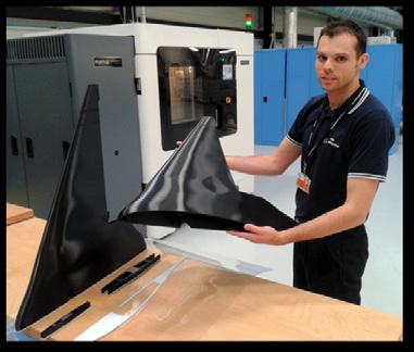

1 AMRC Design and Prototyping Group Case study FDM Printed Fixed Wing UAV amrc.co.uk
 airframe constructed entirely of ABS plastic, using Fused Deposition Modelling (FDM) technology.")
2 DPTC Case Study FDM Printed Fixed Wing UAV AMRC Design and Prototyping Group A team of engineers from the AMRC s new Design & Prototyping Group (DPG) have designed, manufactured and flight tested a prototype Unmanned Aerial Vehicle (UAV) airframe constructed entirely of ABS plastic, using Fused Deposition Modelling (FDM) technology. The recent increase in the use of both additive layer manufacturing and UAVs has led to the availability of a number of 3D printed UAVs for a range of applications. Small wingspan, fixed wing aircraft are used for applications ranging from hobby flying to reconnaissance and humanitarian aid. Key drivers in the development of these vehicles are manufacturing lead time and cost, with additional focus on ease of assembly. With this in mind, the DPG undertook an internal project to design and build a low cost UAV airframe in ABS using their Stratasys Fortus 900mc FDM machine. For printing relatively large components such as a UAV airframe, FDM technology was chosen over stereo lithography and selective laser sintering for its lower initial investment, material cost and simplified process. Ordinarily, an FDM built aircraft would require significant amounts of support material around its component parts to prevent the airframe structures from deforming during the build process. Using support material adds a direct material cost, and significantly increases build time, in some cases by an order of magnitude. This is a result of the machine having to change between build and support structure heads after each printed layer. A more efficient self- supporting design is however constrained to a maximum angle in the machines vertical orientation (layer height). This requirement places onerous geometrical constraints upon the designer, particularly for a small aircraft operating at low Reynolds numbers, where performance depends largely upon a complex combination of specific and accurately orientated geometrical forms.

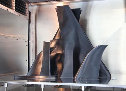
3 The manufacturing aspects of the project were led by Additive Manufacture Development Engineer Mark Cocking: By understanding the capability of the FDM process & associated software, we were able to manipulate the design to contain a number of unique features as well as preventing build deformation. All parts required for the airframe can be combined onto a single build within the DPGs Fortus 900 machine, taking less than 24 hours with ABS- M30 material. Before design for additive manufacture optimisation, this airframe would take over 120 hours to produce. With these constraints in mind, a number of conceptual CAD models were created for evaluation. A range of configurations, sweep angles, chord lengths, taper ratios and aerofoil sections were considered. Development Engineer John Mann was responsible for detail design and CAD modelling of the aircraft: The whole airframe was designed specifically for additive manufacture. The optimum configuration for the diverse requirements of aerodynamic performance and FDM manufacture appeared to be the blended- wing- body. This type of design has a number of advantages: Primarily for this project, it lends itself to FDM technology due to the smooth leading and trailing edges over each half- span. This configuration allowed all geometry to remain below the critical angles beyond which support material would be required. In addition, the aerodynamic advantages over conventional fuselage and wing designs, and its potential as a testing platform for a range of new technologies were considerations during the down selection process.

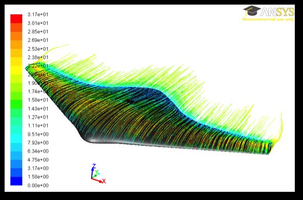
4 Computational Fluid Dynamics (CFD) was used to optimise the chosen design and to assess the lift, drag, pitching moment and other characteristics over a range of angles of incidence. Sam Bull, Development Engineer, conducted these analyses: The final configuration comprised two aerofoil sections blending from a thick, reflexed section in the body to a thinner, conventional section on the outer wing. The trailing edge was extended aft near the centre, where the reflexed aerofoil aids the longitudinal stability of the tailless design. The FDM process also allowed the design to incorporate swept wings with straight leading edges, suited to the low Mach number flight regime the UAV would operate in. The airframe comprises just nine parts, all of which are built using the FDM process: Two wings, two elevons, two spars, two wing end fences and a central spine. None of these components require support material during build. The aircraft was designed to split into two halves about the central spine. This configuration allowed a larger wingspan to be built within the FDM machines build envelope, and made transportation easier. A pair of short spars (front and rear) clip into sockets formed within each wing half, giving a rapid set- up time for flight. The low part count contributes to the rapid manufacturing time for the airframe. The airframe has a wingspan of 1.5 metres, and weighs under 2kg. The internal structure of the wings is a semi- monocoque which has to serve a number of purposes: The unsupported thin walled structures have to withstand becoming distorted as the build height increases during manufacture. Aerodynamic loads around the aerofoil in flight act to distort the skin and create bending moments, especially in manoeuvres. The wing structure has to withstand these loads. Due to the requirement to minimise fixings and reduce part count, the structure has to incorporate a solution for ease of assembly of the two wing halves. In this case, two locating

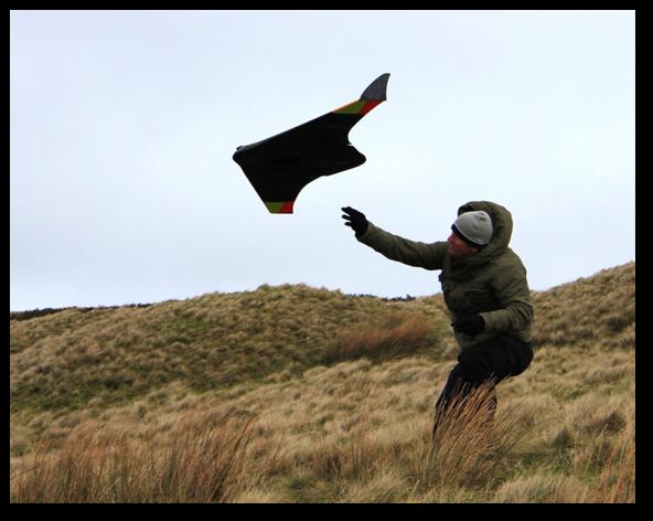
5 spars are used to snap the wings together without any additional fixings, while adding rigidity and strength to counteract launch and flight loads. The control surfaces, in this case trailing edge elevons, were designed to snap fit onto two hinges that protruded from the outer wing section. Elevon control is by means of a direct acting servo in each wing. The servos are fixed onto mounting spigots housed within the aft section of the body. The wing tips are capped by flat end fences which clip into the ends of the aerofoil sections, closing them to span wise airflow and helping to reduce induced drag. The wing end fences also provide a degree of yaw stability, and serve as a retaining structure for the elevons. In order to prove the design, the UAV was flight tested as a radio controlled slope soaring glider. The aircraft showed good stability, and low aerodynamic noise at speed indicated an efficient wing design.


6 Senior Design Engineer Dr. Garth Nicholson oversaw the project: Following successful flight testing, the airframe is currently being optimised further to incorporate blended winglets and twin ducted fan propulsion, to facilitate the target flight envelope. Future planned developments include full on- board data logging of flight parameters, autonomous operation by GPS, and control by surface morphing technology. Concepts for novel ducted fan designs are also being investigated. Through this project, the AMRC s Design and Prototyping Group have demonstrated that design for manufacture of relatively large, thin walled parts can be optimised for the FDM process such that only build material is required without any support structure, thus giving considerable manufacturing time and cost savings.
7 - - For detailed information about the development of the FDM Printed ABS Fixed Wing UAV, contact Dr Garth Nicholson, Senior Design Engineer: g.nicholson@amrc.co.uk For more information on the AMRC s Design and Prototyping Group, contact Craig Roberts, Head of Design: c.roberts@amrc.co.uk
Fundamentals of Model Airplane Building
 The dihedral and sweepback give stability The finished glider ready to launch Fundamentals of Model Airplane Building A Complete Course for Beginners Who Wish to Become Expert. How to Build a Contest Glider-Part
Designed in 2005 by Bernard Burton. Assembly manual Bernard Burton DRAFT 1
 Designed in 2005 by Bernard Burton Assembly manual 2005 - Bernard Burton DRAFT 1 The plans can be requested via this link http://www.gundersonaerodesign.com/m12plansreq.htm The laser kit is available here
The Olympic DLG. (Discus launch glider) by Chris Brislin
 by Chris Brislin") The Olympic DLG (Discus launch glider) by Chris Brislin 1 Contents Parts List/ What you need 3 Before you begin 4 Wing Construction 5-9 Pod Construction 9-13 Tail assembly 13-? Control linkages 9-10 Finishing
The Olympic DLG (Discus launch glider) by Chris Brislin 1 Contents Parts List/ What you need 3 Before you begin 4 Wing Construction 5-9 Pod Construction 9-13 Tail assembly 13-? Control linkages 9-10 Finishing
A Hybrid Trailing Edge Control Surface Concept
 Pınar ARSLAN, Uğur KALKAN, Harun TIRAŞ, İlhan Ozan TUNÇÖZ, Yosheph YANG, Ercan GÜRSES, Melin ŞAHİN, Serkan ÖZGEN, Yavuz YAMAN Department of Aerospace Enginnering, Middle East Technical University Ankara,
ParkJet Builder s Manual
 ParkJet Builder s Manual Thank you for purchasing the ParkJet. The ParkJet is a profile ducted fan airplane that can be flown in a larger park. The ParkJet was initially designed by Scott Stoops and modified
Wing. Gently bend the top of the wing over. With the paper removed, it should produce a nice curve.
 Fuselage Remove the paper in the four areas shown. Basically, from the trailing edge of the canard forward in the three nose segments and on the rear bottom of the fuse. Normal B fold for the sides but
Bed must be leveled and printer adjusted to produce good single layer prints. Measurement and calibration of your filament is highly recommended.
 Printing Instructions: ABS or PET is preferred for durability. Bed must be leveled and printer adjusted to produce good single layer prints. Measurement and calibration of your filament is highly recommended.
Tough warrior. The author's many years of intensive competition are your guarantee of a sturdy, fliable design with all "bugs" eliminated.
 Tough warrior. The author's many years of intensive competition are your guarantee of a sturdy, fliable design with all "bugs" eliminated. LAST month we described the construction of the fuselage and motor
Cefiro: An Aircraft Design Project in the University of Seville
 Cefiro: An Aircraft Design Project in the University of Seville Carlos Bernal Ortega, Andrés Fernández Lucena, Pedro López Teruel, Adrián Martín Cañal, Daniel Pérez Alcaraz, Francisco Samblás Carrasco
C-180 Builder s Manual
 C-180 Builder s Manual. May 20, 2002 Last revised July 11, 2002 Copyright! 2002 Douglas Binder, Mountain Models www.mountainmodels.com sales@mountainmodels.com (719) 630-3186 1 Required Equipment! Xacto
Joint Collaborative Project. between. China Academy of Aerospace Aerodynamics (China) and University of Southampton (UK)
 and University of Southampton (UK)") Joint Collaborative Project between China Academy of Aerospace Aerodynamics (China) and University of Southampton (UK) ~ PhD Project on Performance Adaptive Aeroelastic Wing ~ 1. Abstract The reason for
Joint Collaborative Project between China Academy of Aerospace Aerodynamics (China) and University of Southampton (UK) ~ PhD Project on Performance Adaptive Aeroelastic Wing ~ 1. Abstract The reason for
Tapered Wings. I have attached a documents on tapered wing construction. The round leading edge and constant spars is not a problem.
 TaperedWings Paul: My concerns for the highly tapered wing is the build difficulty and stall characteristics. Remotely piloted aircraft can be difficult to control if the wing isn t built true i.e. free
STRATOSPHERE CONTEST MODEL
 STRATOSPHERE CONTEST MODEL A Super-Duration Fuselage Plane With Extremely High Power-Weight Ratio It Has Made a Flight of Thirty- Five Minutes Construction of the light hut strong frame work is simple
CENTER WING SECTION (CWS) WORK REPORT
 WORK REPORT") CENTER WING SECTION (CWS) WORK REPORT No. Check Parts / Description Qty PHASE 1: Preparations 1 [ ] 6V1-3 Rear ribs 2R & 2L 1 [ ] L Angle 6 2 [ ] 6V2-1 Rear Ribs.032 2R & 2L 2 [ ] 6V5-1 Gear Rib Doubler
CENTER WING SECTION (CWS) WORK REPORT No. Check Parts / Description Qty PHASE 1: Preparations 1 [ ] 6V1-3 Rear ribs 2R & 2L 1 [ ] L Angle 6 2 [ ] 6V2-1 Rear Ribs.032 2R & 2L 2 [ ] 6V5-1 Gear Rib Doubler
Construction on this ship came to
 On the Wing... Redwing XC, Part 4 Fuselage components, vertical fin and rudder Bill & Bunny Kuhlman, bsquared@themacisp.net Construction on this ship came to a near standstill for a couple of months, but
TIGER MOTH 120 ASSEMBLY INSTRUCTIONS
 TIGER MOTH 120 ASSEMBLY INSTRUCTIONS SPECIFICATIONS Wing Span: Length: Radio: Flying Weight: 1920mm 1580mm 4 channel with 6 servos 4200g AILERON ASSEMBLY 1 Start by removing the servo cover from the bottom
COMET 24" HELLCAT REPRODUCTION ASSEMBLY GUIDE
 COMET 24" HELLCAT REPRODUCTION A RUBBER POWERED 24" WING SPAN MODEL BY PAUL BRADLEY ASSEMBLY GUIDE AUGUST 2016 CHANGES MADE TO THE ORIGINAL The following changes were made to the original Comet kit structural
Application of RP Technology with Polycarbonate Material for Wind Tunnel Model Fabrication
 Application of RP Technology with Polycarbonate Material for Wind Tunnel Model Fabrication A. Ahmadi Nadooshan, S. Daneshmand, and C. Aghanajafi Abstract Traditionally, wind tunnel models are made of metal
FLITZEBOGEN-2 Assembly instructions
 FLITZEBOGEN-2 Assembly instructions Trim the end of the fuselage to the length of 925mm from the nose. Be careful to avoid splitting the carbon fibers. Sand the base of the stab mount in preparation for
AMRC Design & Prototyping Group Capability directory
 AMRC Design & Prototyping Group Capability directory The AMRC Design & Prototyping Group undertakes high-risk research to develop novel products, machinery and equipment to help UK manufacturers deliver
Hardware Modeling and Machining for UAV- Based Wideband Radar
 Hardware Modeling and Machining for UAV- Based Wideband Radar By Ryan Tubbs Abstract The Center for Remote Sensing of Ice Sheets (CReSIS) at the University of Kansas is currently implementing wideband
EXPERIMENTAL STUDY OF THE MORPHING FLAP AS A LOW NOISE HIGH LIFT DEVICE FOR AIRCRAFT WING
 28 TH INTERNATIONAL CONGRESS OF THE AERONAUTICAL SCIENCES EXPERIMENTAL STUDY OF THE MORPHING FLAP AS A LOW NOISE HIGH LIFT DEVICE FOR AIRCRAFT WING Yasuhiro TANI*, Yoshiyuki MATSUDA*, Akira DOI*, Yuya
COMET SENIOR DART REPRODUCTION ASSEMBLY GUIDE
 COMET SENIOR DART REPRODUCTION A RUBBER POWERED 24" WING SPAN MODEL BY PAUL BRADLEY ASSEMBLY GUIDE JANUARY 2018 CHANGES MADE TO THE ORIGINAL The following changes were made to the original Comet kit structural
Development of Hybrid Flight Simulator with Multi Degree-of-Freedom Robot
 Development of Hybrid Flight Simulator with Multi Degree-of-Freedom Robot Kakizaki Kohei, Nakajima Ryota, Tsukabe Naoki Department of Aerospace Engineering Department of Mechanical System Design Engineering
Nick Limber s Debby. Debby Gas Job *** *** By Nick Limber
 DON T SKIP THIS Debby Gas Job *** HERE'S ANOTHER SMOOTH LITTLE GAS BUGGY FROM NICK LIMBER DRAWING BOARD. ALL YOU LADS WHO HAVE BUILT NICK'S SLEEK SHIPS KNOW THEY'RE TOP-NOTCH, AND WON'T WANT TO PASS THIS
2.1 Parts List Tool requirement Before you start assembling the Stabiliser Front Spar Center Doublers...
 Stabilizer Assembly 2.0 Exploded View...Error! Bookmark not defined. 2.1 Parts List...3 2.2 Tool requirement...5 2.3 Before you start assembling the Stabiliser...6 2.4 Front Spar...6 2.5 Center Doublers...7
Cover the wing trailing edge and the aileron leading edge with strapping tape as shown.
 Cover the wing trailing edge and the aileron leading edge with strapping tape as shown. The aileron hinges are done using strapping tape on the top and bottom surfaces of the ailerons as shown. Make sure
Comparison between FDM Model and Steel Model as Wind Tunnel Testing Models
 Comparison between FDM Model and Steel Model as Wind Tunnel Testing Models S. DANESHMAND 1, R. ADELNIA 2, S. AGHANAJAFI 3 Mechanical Group, Majlesi Azad University Isfahan IRAN Saeed_daneshmand@yahoo.com,
DRAFT COPY BUILDING INSTRUCTIONS FOR BLACKBURN BUCCANEER S2 VERSION 1 (BETA BUILD) BY MARK DOUGLAS
 BY MARK DOUGLAS") BUILDING INSTRUCTIONS FOR BLACKBURN BUCCANEER S2 VERSION 1 (BETA BUILD) BY MARK DOUGLAS COPYRIGHT MARK DOUGLAS 2011 THIS IS A "SHORT" KIT FOR EXPERIENCED BUILDERS AND FLYERS ONLY, DESIGNED BY A SHED DWELLING
BUILDING INSTRUCTIONS FOR BLACKBURN BUCCANEER S2 VERSION 1 (BETA BUILD) BY MARK DOUGLAS COPYRIGHT MARK DOUGLAS 2011 THIS IS A "SHORT" KIT FOR EXPERIENCED BUILDERS AND FLYERS ONLY, DESIGNED BY A SHED DWELLING
Small Unmanned Aerial Vehicle Simulation Research
 International Conference on Education, Management and Computer Science (ICEMC 2016) Small Unmanned Aerial Vehicle Simulation Research Shaojia Ju1, a and Min Ji1, b 1 Xijing University, Shaanxi Xi'an, 710123,
Additive Inc - RAPID PROTOTYPING
 Additive Inc - RAPID PROTOTYPING Professional 3D Printing - FDM Page 1 / 6 About Us Additive, Inc is among leading rapid prototyping companies specializing in high quality FDM ( Fused Deposition Modeling
DRAWING KEY FOLD TYPES A B C EDGE BEVEL REFERENCE/ OPTIONAL
 RR Finch B DRAWING KEY FOLD TYPES A B C A - FOLD (ABOVE) B - FOLD (BESIDE) C - FOLD (COVER) LINE TYPE/COLOR SYMBOLS PART NUMBER CUT 50% SCORE CREASE NAME MATERIAL MODEL - VERSION QUANTITY 45 DOUBLE BEVEL
Bob's Card Models and [Resources]
![Bob's Card Models and [Resources]](/thumbs/81/83816834.jpg "Bob's Card Models and [Resources]") Bob's Card Models www.bobscardmodels.altervista.org and www.zealot.com [Resources] Grumman Albatross HU-16E 1:72 The Grumman HU-16 Albatross is a large twin-radial engine amphibious flying boat. Originally
Bob's Card Models www.bobscardmodels.altervista.org and www.zealot.com [Resources] Grumman Albatross HU-16E 1:72 The Grumman HU-16 Albatross is a large twin-radial engine amphibious flying boat. Originally
THE STREAMLINER! A super Class D fuselage model
 THE STREAMLINER! A super Class D fuselage model by CHRISTIAN D. BERGER THE two most important characteristics of a contest model are its climb, and gliding ability. For, after all, you have to get up high
96 WING SPAN SPITFIRE (COPYRIGHT PROTECTED 2014) ALL RIGHTS RESERVED
 ALL RIGHTS RESERVED") 96 WING SPAN SPITFIRE (COPYRIGHT PROTECTED 2014) ALL RIGHTS RESERVED GENERAL INSTRUCTIONS Should you elect to use the recommended Door Skin, which is 1/8 mahogany plywood measuring 36 x 88. Have it cut
96 WING SPAN SPITFIRE (COPYRIGHT PROTECTED 2014) ALL RIGHTS RESERVED GENERAL INSTRUCTIONS Should you elect to use the recommended Door Skin, which is 1/8 mahogany plywood measuring 36 x 88. Have it cut
The model boasts of twin fuselages and three fins
 An Experimental Twin Tractor One of the Most Unique and Finest Fliers Ever Presented. If You Want Something Different, Build and Fly This One By FELIX GUTMANN The model boasts of twin fuselages and three
ULS Cherokee. Ultra Low Speed aircraft for indoor RC flying. Zippkits. Specifications: Required to complete:
 Zippkits ULS Cherokee Ultra Low Speed aircraft for indoor RC flying. Specifications: Span- 28 inches Wing Area- 151 Sq/In Wing Loading- 3.0 ounces/ft Weight- 3.5 ounces RTF Build time- 1-2 Hours Radio-
Piper Cherokee /3 scale. Construction Manual
 Piper Cherokee 140 1/3 scale Construction Manual STAB CONSTRUCTION 1. Remove foam cores from cradle and place on flat surface. Inspect pieces before you epoxy halves together making sure leading and trailing
ZupAir ZULU OWNER S MANUAL
 ZupAir ZULU OWNER S MANUAL 1 Introduction Thank you for purchasing the ZupAir Zulu. This glider has excellent performance, a terrific speed-range, responsive handling and great aerobatic capability. A
Performance and Design of UAVs: Test Aircraft Development
 Performance and Design of UAVs: Test Aircraft Development Xavier Perraudin Herbert J. and Selma W. Bernstein Class of 1945 Internship Report Mechanical Engineering and Applied Mechanics University of Pennsylvania
52 ND 3AF INTERNATIONAL CONFERENCE ON APPLIED AERODYNAMICS
 52 ND 3AF INTERNATIONAL CONFERENCE ON APPLIED AERODYNAMICS Numerical sizing of Active Flow Control concepts on the outer wing Lyon, March 28, 2017 Presenter: Jean-Pierre Rosenblum (Dassault Aviation) NUMERICAL
SPUNKY ASSEMBLY MANUAL
 SPUNKY ASSEMBLY MANUAL Please read the tips section at the back of this manual regarding the use of laser cut parts. The proper removal and preparation of these parts is important. When laser cut, some
90 WING SPAN P-51D MUSTANG (COPYRIGHT PROTECTED 2014) ALL RIGHTS RESERVED
 ALL RIGHTS RESERVED") 90 WING SPAN P-51D MUSTANG (COPYRIGHT PROTECTED 2014) ALL RIGHTS RESERVED GENERAL INSTRUCTIONS This design is basically an enlargement of the very popular fun scale Mustang 60 Size. You can build it light
90 WING SPAN P-51D MUSTANG (COPYRIGHT PROTECTED 2014) ALL RIGHTS RESERVED GENERAL INSTRUCTIONS This design is basically an enlargement of the very popular fun scale Mustang 60 Size. You can build it light
Visit of Northrop Grumman. Systems Engineering/ Engineering Design 12/5/16. Jim Scanlan
 Visit of Northrop Grumman Systems Engineering/ Engineering Design 12/5/16 Jim Scanlan Southampton Has eight University Technology Centres; four aerospace related; Rolls-Royce UTC in design Rolls-Royce
PITTS S2S CONSTRUCTION
 PITTS S2S CONSTRUCTION FUSELAGE CONSTRUCTION 1) Place the right fuselage side over the plan and mark the former positions. Place the left side over the right side and mark the former positions. Glue F1
This is the author s final accepted version.
 Dehaeze, F., Allen, C. B. and Barakos, G. N. (2017) The Collaborative Development of New CFD Methods Adapted for Tilt Rotor Aircraft in the HiPerTilt Project. 35th AIAA Applied Aerodynamics Conference,
Classical Control Based Autopilot Design Using PC/104
 Classical Control Based Autopilot Design Using PC/104 Mohammed A. Elsadig, Alneelain University, Dr. Mohammed A. Hussien, Alneelain University. Abstract Many recent papers have been written in unmanned
1 P a g e. P13231 UAV Test Bed Setup Manual
 1 P a g e P13231 UAV Test Bed Setup Manual Table of Contents Introduction....3 Wings... 3-4 Pitot Tube....3 Aileron Fault...4 Accelerometers.4 Fuselage.. 5-8 GPS.5 FPV System..5 ArduPilot 7 GoPro 7 Rudder
SE5a Wing Panels rev 1.0
 SE5a Wing Panels rev 1.0 The top and bottom wings are different. They might look the same but the bottom wing has one less rib and some rib spacing difference. This is due to where the wooden interplane
Thank you for your purchase of the Lee Ulinger, FoamtanaS, Yak-55, or Extra 330 3D Depron foam, Aerobatic airplane.
 Thank you for your purchase of the Lee Ulinger, FoamtanaS, Yak-55, or Extra 330 3D Depron foam, Aerobatic airplane. Tools you will need to build Recommended additional items: #11 hobby knife Motor: Hacker
SPAD. SPAD Derelict. Simple Plastic Airplane Design
 Derelict SPAD Simple Plastic Airplane Design SPAD Derelict The Derelict. This is our third design entry for an RCCA legal open "B" class plane. The main difference in this design is the choice of materials.
FDM Matchplate Patterns for Green Sand Casting
 FDM Matchplate Patterns for Green Sand Casting Sand casting is a cost effective and efficient process for small-lot production, and yet, when using automated equipment, it is an effective manufacturing
MORPHING AIRCRAFT DESIGN TEAM
 VIRGINIA TECH AEROSPACE ENGINEERING SENIOR DESIGN PROJECT Spring Semester Final Design Report 2 May 2002 MORPHING AIRCRAFT DESIGN TEAM Greg Eggleston Caroline Hutchison Chris Johnston Brian Koch Greg Wargo
F-16 Falcon 70mm EDF
 F-16 Falcon 70mm EDF Instruction manual Specifications: Winspan: 640 mm Length: 990 mm Weight: 900-1100 gram Ducted fans 70mm x 1 Required tools and components:. 4 ch. Computer Radio system w/ 2 servos.
Cartoon from the AIAA Northrop F-5 Case Study
 Aircraft Geometry There is a standard terminology We need to make sure we know it We can often work with analytically designed shapes - characterized by a small number of parameters Real airplanes don
DE HAVILLAND DH86 EXPRESS by Ivan Pettigrew Construction Notes
 DE HAVILLAND DH86 EXPRESS by Ivan Pettigrew Construction Notes As a five year old, growing up in New Zealand, the only aeroplanes I had ever seen were single engine biplanes. When they flew low over our
Lockheed Martin 2016 LOCKHEED MARTIN CORPORATION. ALL RIGHTS RESERVED
 Lockheed Martin 1 Helping the Future Arrive 2 Our People 115,000 Employees 60,000 Scientists & Engineers 500+ U.S. Facilities Operating in 70 Countries 3 Lockheed Martin 100+ Years of Accelerating Tomorrow
ESDU by IHS Markit Accelerate Aerospace Design and Development Customer Testimonials from Academia and Commercial Engineers
 ESDU Aerospace Content Discover the data critical to support aerospace and aircraft design in these ESDU data series: Aerodynamics - A wide range of data and methods applicable to aircraft design, atmospheric
The Accuracy Myth DON T MAKE THE MISTAKE OF CONFUSING HIGH RESOLUTION WITH ACCURACY
 By Bonnie Meyer, Stratasys As additive manufacturing is called on to produce parts that do more than look good, there s a growing emphasis on dimensional accuracy and repeatability over resolution. Most
F-16 Quadratic LCO Identification
 Chapter 4 F-16 Quadratic LCO Identification The store configuration of an F-16 influences the flight conditions at which limit cycle oscillations develop. Reduced-order modeling of the wing/store system
Parts Identification
 We are excited to introduce the Model Aero Aqua Sport. This is an excellent sport flyer, equally at home flying from grass fields, water, or even snow! The unique V-tail gives the Aqua Sport a distinctive
Specifications Wingspan: 43cm Flying Weight: 33 grams (with battery) Channels: 3 Suggested Receiver: 4Ch Micro Motor: 7mm Brushed Geardrive
 Channels: 3 Suggested Receiver: 4Ch Micro Motor: 7mm Brushed Geardrive") Specifications Wingspan: 43cm Flying Weight: 33 grams (with battery) Channels: 3 Suggested Receiver: 4Ch Micro Motor: 7mm Brushed Geardrive Airframe Kit (Included Contents) * Airframe Parts Sheets (Depron)
Specifications Wingspan: 43cm Flying Weight: 33 grams (with battery) Channels: 3 Suggested Receiver: 4Ch Micro Motor: 7mm Brushed Geardrive Airframe Kit (Included Contents) * Airframe Parts Sheets (Depron)
Velocity Slingjet. Specifications: Construction Span Length Take-off weight w/ gear. Balsa/foam/film 1055m m (41.54 ) 1040m m (40.
 1040m m (40.") Velocity Slingjet Specifications: Construction Span Length Take-off weight w/ gear Recommended servos w/o nose-steering Recommended fan Recommended motor Recommended controller Balsa/foam/film 1055m m
Velocity Slingjet Specifications: Construction Span Length Take-off weight w/ gear Recommended servos w/o nose-steering Recommended fan Recommended motor Recommended controller Balsa/foam/film 1055m m
INCLUDED IN THIS KIT: SPECIFICATION: NEEDED BUILDING TOOLS: REQUIRED EQUIPMENT:
 Please review this entire manual before beginning assembly. By doing so it will help you better understand each step as you progress in the actual building of your kit, and you will do a better job in
Hobby King Sunbird Build log
 Hobby King Sunbird Build log The Sunbird is a neat kit, with quite a clever interlocking design and a very elegant wingplan reminiscent of the classic Bird of Time. In theory, the design will force all
Hobby Lobby Zip Supplementary instructions Please refer to the included drawings while using these assembly instructions
 Materials needed: 15 or 30 minute epoxy Medium CA Masking tape Scotch tape Servo Tape Wax paper Tools Needed: Pencil or marker Flat building surface Hobby knife or razor blade 7/64" or 3mm drill bit 3/16"
FORWARD FUSELAGE SIDES & REAR TOP SKINS
 FORWARD FUSELAGE SIDES & REAR TOP SKINS WORK REPORT Step No. Check Parts / Tools Qty Preparations. 1 [ ] 6F5-3 Upper Front Longerons 2 2 [ ] 6F5-5 Heel Support 1 3 [ ] 6F5-2 Front Floor Skin 1 3 [ ] Firewall
E-AERO EPP PITTS KIT From BP HOBBIES. Parts Included in kit
 E-AERO EPP PITTS KIT From BP HOBBIES Parts Included in kit Thank you for purchasing the BP Hobbies/E-aero EPP Pitts. Please take the time to read through the instruction manual before beginning the build.
ATI Horizon (AM) Programme helping to build the future Additively
 Programme helping to build the future Additively") ATI Horizon (AM) Programme helping to build the future Additively In Mar 2014, five partners came together to work on a 13.4 million ATI-funded project called ATI Horizon (AM) in order to develop Additive
ATI Horizon (AM) Programme helping to build the future Additively In Mar 2014, five partners came together to work on a 13.4 million ATI-funded project called ATI Horizon (AM) in order to develop Additive
UAV Flight Control Using Flow Control Actuators
 AIAA Atmospheric Flight Mechanics Conference 08-11 August 2011, Portland, Oregon AIAA 2011-6450 UAV Flight Control Using Flow Control Actuators Eric N Johnson, Girish Chowdhary, Rajeev Chandramohan, Anthony
RESolution V2 Manual
 RESolution V2 Manual Note for the German Manual: Yellow Bottle thick CA Pink Bottle Med CA Blue tube 5 minute Epoxy Green tube 90 Minute Epoxy Construction of the Fuselage Step 1: Cover the plan with a
16. Wing Final Assembly and Installation
 Section Objective: Installation and rigging of ailerons. Pitot tube install, and any other wing related items. Required Parts: Left aileron push rod ALA-0072, Right aileron push rod ALA-0073, Push tube
What is Aspect Ratio? Using Aviation to Teach Math Concepts
 What is Aspect Ratio? Using Aviation to Teach Math Concepts Grade Level: 5 through 8 (easily adaptable for younger and older students) Time Required: approximately 90 minutes Overview Using the companion
(Build Instructions)
") (Build Instructions) Specifications * Wingspan: 58cm * Length: 50cm * Flying Weight: 59 grams * Channels: 3 (Rudder Elevator Throttle) * Suggested Receiver: 4Ch Micro * Motor: 8mm GearDrive * Prop: GWS
(Build Instructions) Specifications * Wingspan: 58cm * Length: 50cm * Flying Weight: 59 grams * Channels: 3 (Rudder Elevator Throttle) * Suggested Receiver: 4Ch Micro * Motor: 8mm GearDrive * Prop: GWS
9.3 FUSELAGE ASSEMBLY 14/03/02
 9.3 MATING THE TAIL CONE TO THE CABIN 1) Trim the bottom flange of both FUS-339 side skins on the tailcone assembly as in Figure 1. 2) Remove the bottom two RBULK 2A s of bulkhead A on the tailcone. 3)
REAR FUSELAGE ASSEMBLY
 SECTION 5 Tail Attachments on Fuselage Ref Dwg 8RU-3 The rudder hinge line (HL) is parallel to the aft edge of the fuselage skin SECTION 5 - Page 1 of 9 Looking at the top of the rear fuselage. Stabilizer
Introducing The Cloud Models Westland Whirlwind
 Produced by Cloud Models,Deopham Road,Morley,Wymondham, Norfolk,NR18 9AA E-mail sales@cloudmodels.com web site cloudmodels.com Introducing The Cloud Models Westland Whirlwind By Tricks Thank you for purchasing
High performance 90mm fiberglass jet
 High performance 90mm fiberglass jet Assembly manual For intermediate and advanced fliers only! Specs Wingspan: 1255mm Fuselage length: 1250mm Flying weight: 2600-3000g Wing area: 22.6 dm² Wing loading:
ZODIAC CH 601 Series Kit Aircraft
 ZODIAC CH 601 Series Kit Aircraft THE FOLLOWING IS A DRAFT MANUAL This manual has been written and published strictly for informational purpose. It has been prepared as a guide to facilitate the assembly
3D Fun Flyer Build Guide 30 Span
 3D Fun Flyer Build Guide 30 Span Designed by Me_Wantee RC Groups Thread http://www.rcgroups.com/forums/showthread.php?t=659911&pp=25 My Setup Motor Axi 2212/34 Prop 10 x 4.7 Speedie 18A Servos are eflight
1. Build the bottom first - make sure your table is flat. Build the entire plane using foam safe CA and kicker. The best technique is to spray kicker
 Wxá zç uç `tçué 1. Build the bottom first - make sure your table is flat. Build the entire plane using foam safe CA and kicker. The best technique is to spray kicker on one part and apply a sparing amount
Combat Foamie. An electric powered model made from sheet foam for full contact combat matches. Designed by. Plan by Paul Bradley. Jerry W.
 Combat Foamie An electric powered model made from sheet foam for full contact combat matches Designed by Jerry W. Hagood Plan by Paul Bradley July 2010 Combat Foamie Top View 22.9 CG is 7.3 back from nose
Then there was a lightened, stripped back version using a lighter fans and batteries, without retracts and flaps.
 42 DUCTED FAN HAWK BUILD GUIDE When the design process started I very much wanted two version; a scale model with flaps, retracts, Red Arrows detailing, a more powerful fan, and larger battery capacity.
Note - the nose ribs and are thinner than the main ribs. These nose ribs will use a thinner rib cap than the ribs. This is per design.
 Stabilizer rev 1.2 The SE5a stabilizer is the heartbeat of the tail and is recreated like the full scale version. All tail pieces depend on the stabilizer. It uses the steel fittings, pulleys, inspection
SZD-10 bis CZAPLA ASSEMBLY MANUAL IN PICTURES
 1 RUDDER Plan and parts: 2 Assembly steps: Photo above: glue together rudder spar, ribs and trailing edge. Clamp spar to a flat surface (chipboard on the photo) and make sure the straight aligment of the
Citabria Pro. Aerobatic Parkflyer. by Joel Dirnberger
 Citabria Pro Aerobatic Parkflyer by Joel Dirnberger Revision C: December 21, 2004 Citabria Pro Building Instructions Length: Wingspan: Wing Area: Flying Weight: Wing Loading: Functions: Specifications:
By Pvt. Ted Lanham COULD BE A FREE-FLIGHT JOB OR CONTROLLINER. THIS SEMI-SCALE CLASS B GASSIE HAS EYE-APPEAL, CONTEST-LIKE PERFORMANCE.
 By Pvt. Ted Lanham COULD BE A FREE-FLIGHT JOB OR CONTROLLINER. THIS SEMI-SCALE CLASS B GASSIE HAS EYE-APPEAL, CONTEST-LIKE PERFORMANCE. Rearwin Speedster was used as basis for this design. Model, ready
Taylorcraft Indoor / Cul-De-Sac Flyer
 Taylorcraft Indoor / Cul-De-Sac Flyer Taylocraft Specifications Wingspan: 28.0 in. Wing Area: 117 sq. in. Weight (Ready to Fly): 3.0 3.1 oz. Wing Loading: 3.7 3.8 oz. / sq. ft. LIABILITY RELEASE In that
INCLUDED IN THIS KIT: SPECIFICATION: NEEDED BUILDING TOOLS: REQUIRED EQUIPMENT:
 Please review this entire manual before beginning assembly. By doing so it will help you better understand each step as you progress in the actual building of your kit, and you will do a better job in
D-SEND#2 FLIGHT DEMONSTRATION FOR LOW SONIC BOOM DESIGN TECHNOLOGY
 D-SEND#2 FLIGHT DEMONSTRATION FOR LOW SONIC BOOM DESIGN TECHNOLOGY Masahisa Honda*, Kenji Yoshida* *Japan Aerospace Exploration Agency honda.masahisa@jaxa.jp; yoshida.kenji@jaxa.jp Keywords: D-SEND, sonic
A new benchmarking part for evaluating the accuracy and repeatability of Additive Manufacturing (AM) processes
 processes") A new benchmarking part for evaluating the accuracy and repeatability of Additive Manufacturing (AM) processes Dr Muhammad Fahad, Dr Neil Hopkinson Abstract Additive Manufacturing (AM) refers to a new
A new benchmarking part for evaluating the accuracy and repeatability of Additive Manufacturing (AM) processes Dr Muhammad Fahad, Dr Neil Hopkinson Abstract Additive Manufacturing (AM) refers to a new
FINAL ASSEMBLY- DOORS
 - DOORS DRAWING 8XF-5 ASSEMBLY OF THE DOORS CONTENTS SECTIONS #4a DOOR FRAME #4b DOOR GUSSETS & BOTTOM SKIN #4c DOOR LATCH & STOP Helpful building tips: Use a flat, unwrapped piece of plywood for the door
BOOMERANG TORUS. Aerobatic Sport Jet for 20 to 34 lbs (P80 to P160) thrust turbines.
 thrust turbines.") BOOMERANG TORUS Aerobatic Sport Jet for 20 to 3 lbs (P80 to P160) thrust turbines. Specifications: Span... 83" (2209mm.) Span with Wingtip Tanks 90" (2286mm.) Length...87" (2108mm.) Weight 29 Lbs.(13.15
BOOMERANG TORUS Aerobatic Sport Jet for 20 to 3 lbs (P80 to P160) thrust turbines. Specifications: Span... 83" (2209mm.) Span with Wingtip Tanks 90" (2286mm.) Length...87" (2108mm.) Weight 29 Lbs.(13.15
Design Analysis Process
 Prototype Design Analysis Process Rapid Prototyping What is rapid prototyping? A process that generates physical objects directly from geometric data without traditional tools Rapid Prototyping What is
Reinhard Joachim Huyssen
 CV: RJ Huyssen (December 2014) Reinhard Joachim Huyssen Aeronautical Engineer (MEng) University of Pretoria Career Focus and Specialization Specializing in the art of engineering design, having designed
Design of UAV for photogrammetric mission in Antarctic area
 Design of UAV for photogrammetric mission in Antarctic area Tomasz Goetzendorf-Grabowski Warsaw University of Technology, Warsaw, Poland Nowowiejska 24, 00-665 Warsaw, Poland tgrab@meil.pw.edu.pl Mirosław
Flight control system for a reusable rocket booster on the return flight through the atmosphere
 Flight control system for a reusable rocket booster on the return flight through the atmosphere Aaron Buysse 1, Willem Herman Steyn (M2) 1, Adriaan Schutte 2 1 Stellenbosch University Banghoek Rd, Stellenbosch
WING ASSEMBLY 23.5 (Continued)
") A VERY IMPORTANT NOTE found on many wing drawings states Do not drill any unspecified holes into spar. This is extremely important as any extra holes may, under extreme conditions, WEAKEN THE SPAR. Note;
A VERY IMPORTANT NOTE found on many wing drawings states Do not drill any unspecified holes into spar. This is extremely important as any extra holes may, under extreme conditions, WEAKEN THE SPAR. Note;
Building Tips This model can be built using the following types of adhesives:
 Page 1 Building Tips This model can be built using the following types of adhesives: Epoxy (with or without microballons) Odorless cyanoacrylate (CA) with accelerator UHU Creativ for Styrofoam (or UHU
Your kit contains the following parts. Please check your kit for any missing or damaged parts before starting construction.
 Your kit contains the following parts Please check your kit for any missing or damaged parts before starting construction COMPLETE KIT PARTS LIST 1 Plan Sheet #1 1 Plan Sheet #2 2 Decal Sheet 2 White Tissue