0.1uf ± _ ~P-3T_VIRTUAL. , -1\/V R4 2k0 1k0 ~ K = 1 + R3/R4
|
|
|
- Matilda Reeves
- 6 years ago
- Views:
Transcription
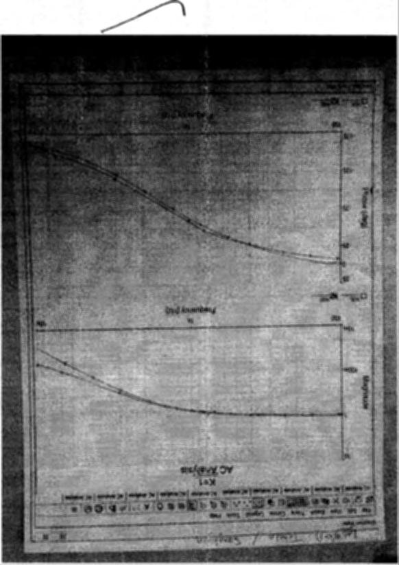
1 ELE Electrical Fundamentals Laboratory II ~ Lab 9 - April 1, 2016 Return of the Sallen Key Filter Gabriel Ortiz The purpose of this lab is to experimentally verify the Multisim simulations that you ran in the pre-lab. Specifically we want to compare the performance of the Sall en Key filter to the 1st order filter. Use Multisim to simulate a first order RC filter with R = lk Ohm and C = 0.1 µf. Print out a plot of the gain and the phase shift with the grid on. The frequency range should be the same used in the pre-lab. We will be plotting the measured points on these graphs. You will need three copies of the graphs. Build the following circuit: XFGl Sallen-Key Low Pass Filter C2, !~----, R1 0.1uf 1k0 R = R1, R2 C = C1, C2 ~~U1 ± _ ~P-3T_VIRTUAL 0.1[F R3, -1\V R4 2k0 1k0 ~ K = 1 + R3R4 2k!l R10 1k0 Sallen Key Output R9 and R3 must be equal to keep the DC gain = 1. Run the above circuit for the following cases. Plot the gain and phase shift on the graphs that you just printed out (don't forget to record the actual numbers in your notebook). 1. Let K = 1 (R3 and R9 = 0). Note that f:e gain of the Sallen Key is always lower than the 1st order. Frequency Gain (Vout Vin) (V) Phase Shift (Degrees) loohz Hz ,; 800Hz khz ' 3 khz \ A12.3 7kHz lokhz ~ ~
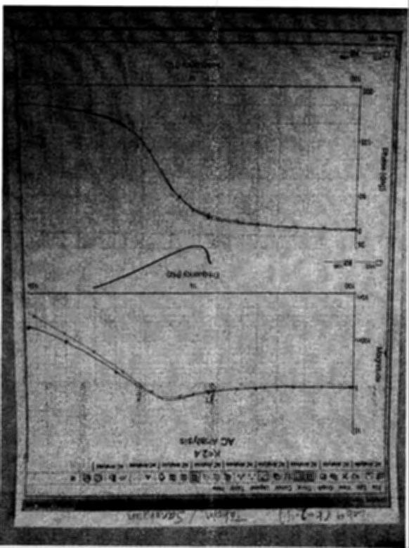
2 2. Let k = 1.6. This is the Butterworth filter. Is the gain always less than or equal to 1? YES. Frequency Gain (VoutNin) (V) Phase Shift (De2rees) loohz Hz lc Hz 0.954,J k" khz ' \...-" 3kHz kHz lokhz Let K = 2.4. (Note, in the pre-lab we used K=2.0). How does the gain of the Sallen Key act at frequencies less than the cutoff frequency? The gain of the Sallen Key is much higher at frequencies less than the cutoff frequency Find the frequency that has the highest gain khz Compare this frequency to the frequency corresponding to the imaginary part of the pole for K = 2.4. The frequency at K = 2.4 is 1.52 khz. Our values are very close Frequency Gain (VoutNin) (V) Phase Shift (De2rees) loohz Hz Hz ~ 1 khz 1.41.;,2'8'.80 3kHz I kHz lokhz Let K = 3. We can adjust the gain so the pole has no real part. At this point the circuit will oscillate. Start by disconnecting the signal generator. Connect Rl to ground. Now, replace R3 with the Decade Box. Don't worry about the changing R9 in the voltage divider. Set R3 so K = 2.8. There should be no output signal. Increase R3 until you see oscillation. If R3 is too high you will see a square wave. Adjusting R3 can be a little tricky. When you get a nice sine wave measure the frequency. Compare the measured frequency to the fr~quency with the maximum gain in the pre- 1~. ' Calculated Frequency= 1592 Hz ~ Our Measured Frequency= 1610 Hz~ They are pretty close to each other.
3 l5 ELE Electrical Fundamentals Laboratory II Lab 2 - February 1, 2016 DC and AC Bridge Circuits Name: Dylan Heh, China Smith Date: Introduction: This lab explores the use of both DC and AC Bridge Circuits. Part 1: Build the circuit below. _L_Vl -=-12 V T ~"~ lokohm DC l~hm ~ Decade Box j Thermister Adjust the decade resistance box until the voltmeter reads zero volts. The bridge is now balanced, and the decade resistance box has the same resistance as the thermistor at ambient temperature. Now grab the thermistor between your finger and thumb and watch the voltmeter change. The bridge is becoming unbalanced because the thermistor's resistance is changing. What is the maximum voltage change you observe? _31 lm ~ Is the thermistor's resistance increasing or decreasing? Increase Byhowmuch? 30on_ Part 2: Build the circuit given in Part 2 of the Pre-Lab. Put the multimeter into the circuit. Set the multimeter for AC Voltage. Note the oscilloscope will not work in this configuration. Change the resistance in the decade box till the output voltage on the multimeter is equal to 0. V=_OV_lOkn ~ Does this match your expectations? - Yes the resistance would equal the other side to balance the bridge
4 Measure each individual component using the multimeter. Use the measured values to recalculate the given formula. Does this better match the data? yes the formula gives the exact value for the bridge to be stable Change C4 to 0.22 uf adjust the decade box to zero the output. R5 = 21k.Q --- Does the formula give a good measure of the capacitance of C4? yes Use an unknown box for C4 the capacitor is between the black.9d the orange banana plugs. Determine the unknown capacitance. Unknown Box = unknown box #5 Capacitance=.0032uF
5 Part 3: Build the circuit given in Part 3 of the Pre-Lab. Measure the AC Voltage for 10 frequencies between 1 khz and 2 khz. Frequency AC Voltage 1 khz.73 V 1.1 khz.68v 1.2 khz.63 V 1.3 khz.61 V 1.4 khz.59v 1.5 khz.59v khz.60v \..' 1.7 khz.60v 1.8 khz.62v 2kHz.67V Is the measured frequency with the lowest AC Voltage the same as the lowest frequency found in the pre-lab? Yes Change Cl and C2 to 0.01 uf. Find the frequency with the lowest AC Voltage. Frequency= 2.lkHz ~ Is this what you would expect based on the formula No Note the accuracy of the AC part of the Multimeter losses accuracy as the frequency increases.
6 ELE Electrical Fundamentals Laboratory II Lab 10 - April 8, 2016 The Boost Converter Tahsin Tahmid Part 1: Build the circuit below, which is a boost converter. For the lab, I replaced some of the components used in the pre-lab with better components. If there are no IRF530 transistors available, you can substitute a 2N7000. In the circuit below there is no resistor between Ll and Vl as in the pre-lab. This resistor is not needed since Ll already has some resistance. Vl should go from 0-5 V. We can do this by using the CMOS output on the function generator. Measure the voltage across the 1 on resistor with the oscilloscope to monitor the current through the inductor (V = IR). Determine the maximum current through the inductor. Are there any discontinuities in the inductor's current? (Does the current through the inductor ever chang~tly?) Max Current : 310 A= 0.3A. ~ There are no discontinuity. Now measure the output voltage on the other channel. What is the output voltage? Vout = 7.5 V V2 -=-sv ~ - 3 (ct; V1 R1 2kHz 10 n 5V 01 1mH 1N4002GP --~-~ Q1 4 IRF530NS +I C1 10uF 5 Rload 1k0 0 Vout Part 2: We will now measure the voltage, output ripple and efficiency of the boost converter as a function of duty cycle of the input square wave. First replace the 10 ohm resistor with a wire (this will significantly increase the output voltage). Put one oscilloscope probe on the input square wave. Put the second probe on the output. Measure the output voltage, the voltage ripple and calculate the efficiency for duty cycles of.2,.5 and.8. The output ripple is just the variation in the output voltage divided by the mean output voltage. The efficiency is just the power that is dissipated in R1oad (V 2 R) divided by the power into the system from V2 (from the power supply, take the voltage and the current and multiply them). Change R1oad to 2000 ohms. Repeat the measurements. Change R1oad to 470 ohms. Repeat the measurements.
7 Out C cle Out ut 0.2 Vout= Ripple= Efficiency= R=lkO 12.5V 5.76% 63.8% R=2k0 17.4V 8.05% 67.3% R= V 16.1% 65.7% ~ 0.5 I Vout= Ripple= Efficiency= 0.8 Vout= Ripple= Efficiencv= 15V 9.33% 26.0% 13.3 V 10.5% 14.0% 20.2 V 5.94% % 4.37% 17.8% 15.9% Part 3: Make a comment in your report about how a regulated switching power supply can be made. A regulated supply is a power supply that maintains a fixed output voltage ( e.g. 15V) regardless of the load (the amount of current drawn from th~ power supply). We can alter the duty cycle to regulate the power s. I voltage. Important Note: The power rating of Rtoad is V,i Watt. You will be operating the resister at about 1 W. The resister will heat up! Since you are only running for a short period of time, you should be o.k. But don't touch it. L
8 -
9 --.
EK307 Active Filters and Steady State Frequency Response
 EK307 Active Filters and Steady State Frequency Response Laboratory Goal: To explore the properties of active signal-processing filters Learning Objectives: Active Filters, Op-Amp Filters, Bode plots Suggested
Theory: The idea of this oscillator comes from the idea of positive feedback, which is described by Figure 6.1. Figure 6.1: Positive Feedback
 Name1 Name2 12/2/10 ESE 319 Lab 6: Colpitts Oscillator Introduction: This lab introduced the concept of feedback in combination with bipolar junction transistors. The goal of this lab was to first create
UNIVERSITY OF TECHNOLOGY, JAMAICA SCHOOL OF ENGENEERING. Electrical Engineering Science. Laboratory Manual
 UNIVERSITY OF TECHNOLOGY, JAMAICA SCHOOL OF ENGENEERING Electrical Engineering Science Laboratory Manual Table of Contents Experiment #1 OHM S LAW... 3 Experiment # 2 SERIES AND PARALLEL CIRCUITS... 8
Experiment 2 Electric Circuit Fundamentals
 Experiment 2 Electric Circuit Fundamentals Introduction This experiment has two parts. Each part will have to be carried out using the Multisim Electronics Workbench software. The experiment will then
Chapter 1: DC circuit basics
 Chapter 1: DC circuit basics Overview Electrical circuit design depends first and foremost on understanding the basic quantities used for describing electricity: Voltage, current, and power. In the simplest
Exercise 2: High-Pass Filters
 Exercise 2: High-Pass Filters EXERCISE OBJECTIVE When you have completed this exercise, you will be able to calculate and measure the cutoff frequencies oscilloscope. DISCUSSION of inductors, capacitors,
UNIVERSITY OF TECHNOLOGY, JAMAICA School of Engineering -
 UNIVERSITY OF TECHNOLOGY, JAMAICA School of Engineering - Electrical Engineering Science Laboratory Manual Table of Contents Safety Rules and Operating Procedures... 3 Troubleshooting Hints... 4 Experiment
SKEU 3741 BASIC ELECTRONICS LAB
 Faculty: Subject Subject Code : SKEU 3741 FACULTY OF ELECTRICAL ENGINEERING : 2 ND YEAR ELECTRONIC DESIGN LABORATORY Review Release Date Last Amendment Procedure Number : 1 : 2013 : 2013 : PK-UTM-FKE-(0)-10
Lab 4: Analysis of the Stereo Amplifier
 ECE 212 Spring 2010 Circuit Analysis II Names: Lab 4: Analysis of the Stereo Amplifier Objectives In this lab exercise you will use the power supply to power the stereo amplifier built in the previous
Lab 1: Basic RL and RC DC Circuits
 Name- Surname: ID: Department: Lab 1: Basic RL and RC DC Circuits Objective In this exercise, the DC steady state response of simple RL and RC circuits is examined. The transient behavior of RC circuits
University of Michigan EECS 311: Electronic Circuits Fall 2008 LAB 2 ACTIVE FILTERS
 University of Michigan EECS 311: Electronic Circuits Fall 2008 LAB 2 ACTIVE FILTERS Issued 9/22/2008 Pre Lab Completed 9/29/2008 Lab Due in Lecture 10/6/2008 Introduction In this lab you will design a
Chapter 1: DC circuit basics
 Chapter 1: DC circuit basics Overview Electrical circuit design depends first and foremost on understanding the basic quantities used for describing electricity: voltage, current, and power. In the simplest
EE 210: CIRCUITS AND DEVICES
 EE 210: CIRCUITS AND DEVICES LAB #3: VOLTAGE AND CURRENT MEASUREMENTS This lab features a tutorial on the instrumentation that you will be using throughout the semester. More specifically, you will see
Lab #2: Electrical Measurements II AC Circuits and Capacitors, Inductors, Oscillators and Filters
 Lab #2: Electrical Measurements II AC Circuits and Capacitors, Inductors, Oscillators and Filters Goal: In circuits with a time-varying voltage, the relationship between current and voltage is more complicated
ECE 53A: Fundamentals of Electrical Engineering I
 ECE 53A: Fundamentals of Electrical Engineering I Laboratory Assignment #1: Instrument Operation, Basic Resistor Measurements and Kirchhoff s Laws Fall 2007 General Guidelines: - Record data and observations
Lab #2: Electrical Measurements II AC Circuits and Capacitors, Inductors, Oscillators and Filters
 Lab #2: Electrical Measurements II AC Circuits and Capacitors, Inductors, Oscillators and Filters Goal: In circuits with a time-varying voltage, the relationship between current and voltage is more complicated
Lab 5 Second Order Transient Response of Circuits
 Lab 5 Second Order Transient Response of Circuits Lab Performed on November 5, 2008 by Nicole Kato, Ryan Carmichael, and Ti Wu Report by Ryan Carmichael and Nicole Kato E11 Laboratory Report Submitted
Experiment 9 AC Circuits
 Experiment 9 AC Circuits "Look for knowledge not in books but in things themselves." W. Gilbert (1540-1603) OBJECTIVES To study some circuit elements and a simple AC circuit. THEORY All useful circuits
The Series RLC Circuit and Resonance
 Purpose Theory The Series RLC Circuit and Resonance a. To study the behavior of a series RLC circuit in an AC current. b. To measure the values of the L and C using the impedance method. c. To study the
ECE212H1F University of Toronto 2017 EXPERIMENT #4 FIRST AND SECOND ORDER CIRCUITS ECE212H1F
 ECE212H1F University of Toronto 2017 EXPERIMENT #4 FIRST AND SECOND ORDER CIRCUITS ECE212H1F OBJECTIVES: To study the voltage-current relationship for a capacitor. To study the step responses of a series
Lab 3: AC Low pass filters (version 1.3)
") Lab 3: AC Low pass filters (version 1.3) WARNING: Use electrical test equipment with care! Always double-check connections before applying power. Look for short circuits, which can quickly destroy expensive
Lab 3: AC Low pass filters (version 1.3) WARNING: Use electrical test equipment with care! Always double-check connections before applying power. Look for short circuits, which can quickly destroy expensive
PHYS 3322 Modern Laboratory Methods I AC R, RC, and RL Circuits
 Purpose PHYS 3322 Modern Laboratory Methods I AC, C, and L Circuits For a given frequency, doubling of the applied voltage to resistors, capacitors, and inductors doubles the current. Hence, each of these
ECE ECE285. Electric Circuit Analysis I. Spring Nathalia Peixoto. Rev.2.0: Rev Electric Circuits I
 ECE285 Electric Circuit Analysis I Spring 2014 Nathalia Peixoto Rev.2.0: 140124. Rev 2.1. 140813 1 Lab reports Background: these 9 experiments are designed as simple building blocks (like Legos) and students
ECE 2010 Laboratory # 5 J.P.O Rourke
 ECE 21 Laboratory # 5 J.P.O Rourke Prelab: Simulate the circuit used in parts 1 and 2 of the Lab and record the simulated results. Your Prelab is due at the beginning of lab and will be checked off by
Study of Inductive and Capacitive Reactance and RLC Resonance
 Objective Study of Inductive and Capacitive Reactance and RLC Resonance To understand how the reactance of inductors and capacitors change with frequency, and how the two can cancel each other to leave
Control System Circuits with Opamps
 Control System Circuits with Opamps 27.04.2009 Purpose To introduce opamps, transistors and their usage To apply a control system with analog circuit elements. Difference Amplifier Figure 1 Basic Difference
EXPERIMENT 8: LRC CIRCUITS
 EXPERIMENT 8: LRC CIRCUITS Equipment List S 1 BK Precision 4011 or 4011A 5 MHz Function Generator OS BK 2120B Dual Channel Oscilloscope V 1 BK 388B Multimeter L 1 Leeds & Northrup #1532 100 mh Inductor
BEST BMET CBET STUDY GUIDE MODULE ONE
 BEST BMET CBET STUDY GUIDE MODULE ONE 1 OCTOBER, 2008 1. The phase relation for pure capacitance is a. current leads voltage by 90 degrees b. current leads voltage by 180 degrees c. current lags voltage
DC Power Supply Design
 Sopczynski 1 John Sopczynski EE 310 Section 4 DC Power Supply Design Introduction The goal of this experiment was to design a DC power supply. Our team would be receiving 120 Vrms oscillating at 60 Hz
LABORATORY #3 QUARTZ CRYSTAL OSCILLATOR DESIGN
 LABORATORY #3 QUARTZ CRYSTAL OSCILLATOR DESIGN OBJECTIVES 1. To design and DC bias the JFET transistor oscillator for a 9.545 MHz sinusoidal signal. 2. To simulate JFET transistor oscillator using MicroCap
EXPERIMENT #2 CARRIER OSCILLATOR
 EXPERIMENT #2 CARRIER OSCILLATOR INTRODUCTION: The oscillator is usually the first stage of any transmitter. Its job is to create a radio-frequency carrier that can be amplified and modulated before being
Project 6: Oscillator Circuits
 : Oscillator Circuits Ariel Moss The purpose of this experiment was to design two oscillator circuits: a Wien-Bridge oscillator at 3 khz oscillation and a Hartley Oscillator using a BJT at 5 khz oscillation.
ECE 2274 Lab 2. Your calculator will have a setting that will automatically generate the correct format.
 ECE 2274 Lab 2 Forward (DO NOT TURN IN) You are expected to use engineering exponents for all answers (p,n,µ,m, N/A, k, M, G) and to give each with a precision between one and three leading digits and
Exercise 1: Inductors
 Exercise 1: Inductors EXERCISE OBJECTIVE When you have completed this exercise, you will be able to describe the effect an inductor has on dc and ac circuits by using measured values. You will verify your
ELECTRICAL CIRCUITS LABORATORY MANUAL (II SEMESTER)
") ELECTRICAL CIRCUITS LABORATORY MANUAL (II SEMESTER) LIST OF EXPERIMENTS. Verification of Ohm s laws and Kirchhoff s laws. 2. Verification of Thevenin s and Norton s Theorem. 3. Verification of Superposition
ELECTRICAL CIRCUITS LABORATORY MANUAL (II SEMESTER) LIST OF EXPERIMENTS. Verification of Ohm s laws and Kirchhoff s laws. 2. Verification of Thevenin s and Norton s Theorem. 3. Verification of Superposition
ECE 2274 Lab 2 (Network Theorems)
") ECE 2274 Lab 2 (Network Theorems) Forward (DO NOT TURN IN) You are expected to use engineering exponents for all answers (p,n,µ,m, N/A, k, M, G) and to give each with a precision between one and three
ECE 2274 Lab 2 (Network Theorems) Forward (DO NOT TURN IN) You are expected to use engineering exponents for all answers (p,n,µ,m, N/A, k, M, G) and to give each with a precision between one and three
AC Measurements with the Agilent 54622D Oscilloscope
 AC Measurements with the Agilent 54622D Oscilloscope Objectives: At the end of this experiment you will be able to do the following: 1. Correctly configure the 54622D for measurement of voltages. 2. Perform
Exercise 1: Series Resonant Circuits
 Series Resonance AC 2 Fundamentals Exercise 1: Series Resonant Circuits EXERCISE OBJECTIVE When you have completed this exercise, you will be able to compute the resonant frequency, total current, and
Experiment #6: Biasing an NPN BJT Introduction to CE, CC, and CB Amplifiers
 SCHOOL OF ENGINEERING AND APPLIED SCIENCE DEPARTMENT OF ELECTRICAL AND COMPUTER ENGINEERING ECE 2115: ENGINEERING ELECTRONICS LABORATORY Experiment #6: Biasing an NPN BJT Introduction to CE, CC, and CB
Class #7: Experiment L & C Circuits: Filters and Energy Revisited
 Class #7: Experiment L & C Circuits: Filters and Energy Revisited In this experiment you will revisit the voltage oscillations of a simple LC circuit. Then you will address circuits made by combining resistors
ANALOG ELECTRONIC CIRCUITS LABORATORY MANUAL (CODE: EEE - 228)
") ANALOG ELECTRONIC CIRCUITS LABORATORY MANUAL (CODE: EEE - 228) DEPARTMENT OF ELECTRONICS & COMMUNICATION ENGINEERING ANIL NEERUKONDA INSTITUTE OF TECHNOLOGY & SCIENCES (Affiliated to AU, Approved by AICTE
ANALOG ELECTRONIC CIRCUITS LABORATORY MANUAL (CODE: EEE - 228) DEPARTMENT OF ELECTRONICS & COMMUNICATION ENGINEERING ANIL NEERUKONDA INSTITUTE OF TECHNOLOGY & SCIENCES (Affiliated to AU, Approved by AICTE
Power Electronics Laboratory-2 Uncontrolled Rectifiers
 Roll. No: Checked By: Date: Grade: Power Electronics Laboratory-2 and Uncontrolled Rectifiers Objectives: 1. To analyze the working and performance of a and half wave uncontrolled rectifier. 2. To analyze
EXPERIMENT 1: Characteristics of Passive and Active Filters
 Kathmandu University Department of Electrical and Electronics Engineering ELECTRONICS AND ANALOG FILTER DESIGN LAB EXPERIMENT : Characteristics of Passive and Active Filters Objective: To understand the
Laboratory 4: Amplification, Impedance, and Frequency Response
 ES 3: Introduction to Electrical Systems Laboratory 4: Amplification, Impedance, and Frequency Response I. GOALS: In this laboratory, you will build an audio amplifier using an LM386 integrated circuit.
BJT Fundamentals and Applications JOR
 Purpose: BJT Fundamentals and Applications JOR The purpose of this assignment is to design a Pulse Amplifier and a Common-Emitter Amplifier with voltage divider bias using a 2N2222A NPN bipolar junction
When you have completed this exercise, you will be able to determine the frequency response of an
 RC Coupling When you have completed this exercise, you will be able to determine the frequency response of an oscilloscope. The way in which the gain varies with frequency is called the frequency response.
ET1210: Module 5 Inductance and Resonance
 Part 1 Inductors Theory: When current flows through a coil of wire, a magnetic field is created around the wire. This electromagnetic field accompanies any moving electric charge and is proportional to
Resonant Frequency of the LRC Circuit (Power Output, Voltage Sensor)
") 72 Resonant Frequency of the LRC Circuit (Power Output, Voltage Sensor) Equipment List Qty Items Part Numbers 1 PASCO 750 Interface 1 Voltage Sensor CI-6503 1 AC/DC Electronics Laboratory EM-8656 2 Banana
72 Resonant Frequency of the LRC Circuit (Power Output, Voltage Sensor) Equipment List Qty Items Part Numbers 1 PASCO 750 Interface 1 Voltage Sensor CI-6503 1 AC/DC Electronics Laboratory EM-8656 2 Banana
On-Line Students Analog Discovery 2: Arbitrary Waveform Generator (AWG). Two channel oscilloscope
. Two channel oscilloscope") EET 150 Introduction to EET Lab Activity 5 Oscilloscope Introduction Required Parts, Software and Equipment Parts Figure 1, Figure 2, Figure 3 Component /Value Quantity Resistor 10 kω, ¼ Watt, 5% Tolerance
EET 150 Introduction to EET Lab Activity 5 Oscilloscope Introduction Required Parts, Software and Equipment Parts Figure 1, Figure 2, Figure 3 Component /Value Quantity Resistor 10 kω, ¼ Watt, 5% Tolerance
Physics 310 Lab 4 Transformers, Diodes, & Power Supplies
 Physics 310 Lab 4 Transformers, Diodes, & Power Supplies Equipment: O scope, W02G Bridge Rectifier, 110 6.3V transformer, four 1N4004 diodes, 1k, 10µF, 100µF, 1N5231 Zeener diode, ½ - Watt 100 Ω, 270Ω,
Frequency Selective Circuits
 Lab 15 Frequency Selective Circuits Names Objectives in this lab you will Measure the frequency response of a circuit Determine the Q of a resonant circuit Build a filter and apply it to an audio signal
EE 2274 RC and Op Amp Circuit Completed Prior to Coming to Lab. Prelab Part I: RC Circuit
 EE 2274 RC and Op Amp Circuit Completed Prior to Coming to Lab Prelab Part I: RC Circuit 1. Design a high pass filter (Fig. 1) which has a break point f b = 1 khz at 3dB below the midband level (the -3dB
LAB 4 : FET AMPLIFIERS
 LEARNING OUTCOME: LAB 4 : FET AMPLIFIERS In this lab, students design and implement single-stage FET amplifiers and explore the frequency response of the real amplifiers. Breadboard and the Analog Discovery
RC and RL Circuits. Figure 1: Capacitor charging circuit.
 RC and RL Circuits Page 1 RC and RL Circuits RC Circuits In this lab we study a simple circuit with a resistor and a capacitor from two points of view, one in time and the other in frequency. The viewpoint
Lab 2: Linear and Nonlinear Circuit Elements and Networks
 OPTI 380B Intermediate Optics Laboratory Lab 2: Linear and Nonlinear Circuit Elements and Networks Objectives: Lean how to use: Function of an oscilloscope probe. Characterization of capacitors and inductors
Lab E5: Filters and Complex Impedance
 E5.1 Lab E5: Filters and Complex Impedance Note: It is strongly recommended that you complete lab E4: Capacitors and the RC Circuit before performing this experiment. Introduction Ohm s law, a well known
PHYSICS 221 LAB #6: CAPACITORS AND AC CIRCUITS
 Name: Partners: PHYSICS 221 LAB #6: CAPACITORS AND AC CIRCUITS The electricity produced for use in homes and industry is made by rotating coils of wire in a magnetic field, which results in alternating
BME (311) Electric Circuits lab
 Electric Circuits lab") Summer 2016 Facility of Engineering Department of Biomedical Engineering BME (311) Electric Circuits lab Prepared By: Eng. Hala Amari Supervised By: Dr. Areen AL-Bashir Table of Contents Experiment # 1
Summer 2016 Facility of Engineering Department of Biomedical Engineering BME (311) Electric Circuits lab Prepared By: Eng. Hala Amari Supervised By: Dr. Areen AL-Bashir Table of Contents Experiment # 1
Electric Circuit Fall 2017 Lab10. LABORATORY 10 RLC Circuits. Guide. Figure 1: Voltage and current in an AC circuit.
 LABORATORY 10 RLC Circuits Guide Introduction RLC circuit When an AC signal is input to a RLC circuit, voltage across each element varies as a function of time. The voltage will oscillate with a frequency
ANADOLU UNIVERSITY FACULTY OF ENGINEERING AND ARCHITECTURE DEPARTMENT OF ELECTRICAL AND ELECTRONICS ENGINEERING
 ANADOLU UNIVERSITY FACULTY OF ENGINEERING AND ARCHITECTURE DEPARTMENT OF ELECTRICAL AND ELECTRONICS ENGINEERING EEM 206 ELECTRICAL CIRCUITS LABORATORY EXPERIMENT#3 RESONANT CIRCUITS 1 RESONANT CIRCUITS
ENG 100 Lab #2 Passive First-Order Filter Circuits
 ENG 100 Lab #2 Passive First-Order Filter Circuits In Lab #2, you will construct simple 1 st -order RL and RC filter circuits and investigate their frequency responses (amplitude and phase responses).
LABORATORY 7 v2 BOOST CONVERTER
 University of California Berkeley Department of Electrical Engineering and Computer Sciences EECS 100, Professor Bernhard Boser LABORATORY 7 v2 BOOST CONVERTER In many situations circuits require a different
Testing Power Factor Correction Circuits For Stability
 Keywords Venable, frequency response analyzer, impedance, injection transformer, oscillator, feedback loop, Bode Plot, power supply design, switching power supply, PFC, boost converter, flyback converter,
University of North Carolina, Charlotte Department of Electrical and Computer Engineering ECGR 3157 EE Design II Fall 2009
 University of North Carolina, Charlotte Department of Electrical and Computer Engineering ECGR 3157 EE Design II Fall 2009 Lab 1 Power Amplifier Circuits Issued August 25, 2009 Due: September 11, 2009
Exercise 2: Parallel RLC Circuits
 RLC Circuits AC 2 Fundamentals Exercise 2: Parallel RLC Circuits EXERCSE OBJECTVE When you have completed this exercise, you will be able to analyze parallel RLC circuits by using calculations and measurements.
Exercise 2: Inductors in Series and in Parallel
 Exercise 2: Inductors in Series and in Parallel EXERCISE OBJECTIVE When you have completed this exercise, you will be able to determine the total inductance of a circuit containing inductors in series
Basic DC Power Supply
 Basic DC Power Supply Equipment: 1. Analog Oscilloscope 2. Digital multimeter 3. Experimental board and connectors. Objectives: 1. To understand the basic DC power supply both half wave and full wave rectifier.
DEPARTMENT OF ELECTRICAL ENGINEERING LAB WORK EE301 ELECTRONIC CIRCUITS
 DEPARTMENT OF ELECTRICAL ENGINEERING LAB WORK EE301 ELECTRONIC CIRCUITS EXPERIMENT : 5 TITLE : ACTIVE FILTERS OUTCOME : Upon completion of this unit, the student should be able to: 1. gain experience with
Exercise 3: Power in a Series/Parallel Circuit
 DC Fundamentals Power in DC Circuits Exercise 3: Power in a Series/Parallel Circuit EXERCISE OBJECTIVE When you have completed this exercise, you will be able to determine the power dissipated in a series/
A 3-STAGE 5W AUDIO AMPLIFIER
 ECE 2201 PRELAB 7x BJT APPLICATIONS A 3-STAGE 5W AUDIO AMPLIFIER UTILIZING NEGATIVE FEEDBACK INTRODUCTION Figure P7-1 shows a simplified schematic of a 3-stage audio amplifier utilizing three BJT amplifier
Power supply circuits
 Power supply circuits Practical exercise in Analog Electronics Abstract In this lab some different power supply circuits should be characterized. 1 Introduction he four basic constituents of a power supply
Lab Exercise # 9 Operational Amplifier Circuits
 Objectives: THEORY Lab Exercise # 9 Operational Amplifier Circuits 1. To understand how to use multiple power supplies in a circuit. 2. To understand the distinction between signals and power. 3. To understand
Precalculations Individual Portion Filter Lab: Building and Testing Electrical Filters
 Name: Date of lab: Section number: M E 345. Lab 6 Precalculations Individual Portion Filter Lab: Building and Testing Electrical Filters Precalculations Score (for instructor or TA use only): / 20 1. (4)
PHY203: General Physics III Lab page 1 of 5 PCC-Cascade. Lab: AC Circuits
 PHY203: General Physics III Lab page 1 of 5 Lab: AC Circuits OBJECTIVES: EQUIPMENT: Universal Breadboard (Archer 276-169) 2 Simpson Digital Multimeters (464) Function Generator (Global Specialties 2001)*
Uncovering a Hidden RCL Series Circuit
 Purpose Uncovering a Hidden RCL Series Circuit a. To use the equipment and techniques developed in the previous experiment to uncover a hidden series RCL circuit in a box and b. To measure the values of
University of Portland EE 271 Electrical Circuits Laboratory. Experiment: Inductors
 University of Portland EE 271 Electrical Circuits Laboratory Experiment: Inductors I. Objective The objective of this experiment is to verify the relationship between voltage and current in an inductor,
Lab 3 Transient Response of RC & RL Circuits
 Lab 3 Transient Response of RC & RL Circuits Last Name: First Name: Student Number: Lab Section: Monday Tuesday Wednesday Thursday Friday TA Signature: Note: The Pre-Lab section must be completed prior
BME 3512 Bioelectronics Laboratory Six - Active Filters
 BME 5 Bioelectronics Laboratory Six - Active Filters Learning Objectives: Understand the basic principles of active filters. Describe the differences between active and passive filters. Laboratory Equipment:
ECEN Network Analysis Section 3. Laboratory Manual
 ECEN 3714----Network Analysis Section 3 Laboratory Manual LAB 07: Active Low Pass Filter Oklahoma State University School of Electrical and Computer Engineering. Section 3 Laboratory manual - 1 - Spring
SENSOR AND MEASUREMENT EXPERIMENTS
 SENSOR AND MEASUREMENT EXPERIMENTS Page: 1 Contents 1. Capacitive sensors 2. Temperature measurements 3. Signal processing and data analysis using LabVIEW 4. Load measurements 5. Noise and noise reduction
LABORATORY 3 v1 CIRCUIT ELEMENTS
 University of California Berkeley Department of Electrical Engineering and Computer Sciences EECS 100, Professor Bernhard Boser LABORATORY 3 v1 CIRCUIT ELEMENTS The purpose of this laboratory is to familiarize
II. Experimental Procedure
 Ph 122 July 27, 2006 Ohm's Law http://www.physics.sfsu.edu/~manuals/ph122/ I. Theory In this lab we will make detailed measurements on one resistor to see if it obeys Ohm's law. We will also verify the
Exercise 1: Power Division
 Power in AC Circuits AC 2 Fundamentals Exercise 1: Power Division EXERCISE OBJECTIVE When you have completed this exercise, you will be able to determine ac power division among the components of an RLC
Exercise 2: Q and Bandwidth of a Series RLC Circuit
 Series Resonance AC 2 Fundamentals Exercise 2: Q and Bandwidth of a Series RLC Circuit EXERCISE OBJECTIVE When you have completed this exercise, you will be able to calculate the bandwidth and Q of a series
DEPARTMENT OF ELECTRICAL ENGINEERING AND COMPUTER SCIENCE MASSACHUSETTS INSTITUTE OF TECHNOLOGY CAMBRIDGE, MASSACHUSETTS 02139
 DEPARTMENT OF ELECTRICAL ENGINEERING AND COMPUTER SCIENCE MASSACHUSETTS INSTITUTE OF TECHNOLOGY CAMBRIDGE, MASSACHUSETTS 039 READING ASSIGNMENT Spring Term 007 6.0 Introductory Analog Electronics Laboratory
Check out from stockroom:! Two 10x scope probes
 University of Utah Electrical & Computer Engineering Department ECE 3510 Lab 6 Basic Phase - Locked Loop M. Bodson, A. Stolp, 2/26/06 rev,3/1/09 Note : Bring a proto board, parts, and lab card this week.
AC Circuits. "Look for knowledge not in books but in things themselves." W. Gilbert ( )
") AC Circuits "Look for knowledge not in books but in things themselves." W. Gilbert (1540-1603) OBJECTIVES To study some circuit elements and a simple AC circuit. THEORY All useful circuits use varying
AC Circuits "Look for knowledge not in books but in things themselves." W. Gilbert (1540-1603) OBJECTIVES To study some circuit elements and a simple AC circuit. THEORY All useful circuits use varying
EK307 Passive Filters and Steady State Frequency Response
 EK307 Passive Filters and Steady State Frequency Response Laboratory Goal: To explore the properties of passive signal-processing filters Learning Objectives: Passive filters, Frequency domain, Bode plots
Week 8 AM Modulation and the AM Receiver
 Week 8 AM Modulation and the AM Receiver The concept of modulation and radio transmission is introduced. An AM receiver is studied and the constructed on the prototyping board. The operation of the AM
Non-ideal Behavior of Electronic Components at High Frequencies and Associated Measurement Problems
 Nonideal Behavior of Electronic Components at High Frequencies and Associated Measurement Problems Matthew Beckler beck0778@umn.edu EE30 Lab Section 008 October 27, 2006 Abstract In the world of electronics,
EE 241 Experiment #7: NETWORK THEOREMS, LINEARITY, AND THE RESPONSE OF 1 ST ORDER RC CIRCUITS 1
 EE 241 Experiment #7: NETWORK THEOREMS, LINEARITY, AND THE RESPONSE OF 1 ST ORDER RC CIRCUITS 1 PURPOSE: To verify the validity of Thevenin and maximum power transfer theorems. To demonstrate the linear
Electronics II. 3. measurement : Tuned circuits
 Electronics II. 3. measurement : Tuned circuits This laboratory session involves circuits which contain a double-t (or TT), a passive RC circuit: Figure 1. Double T passive RC circuit module The upper
Series and Parallel Resonant Circuits
 Series and Parallel Resonant Circuits Aim: To obtain the characteristics of series and parallel resonant circuits. Apparatus required: Decade resistance box, Decade inductance box, Decade capacitance box
EXPERIMENT NUMBER 8 Introduction to Active Filters
 EXPERIMENT NUMBER 8 Introduction to Active Filters i-1 Preface: Preliminary exercises are to be done and submitted individually. Laboratory hardware exercises are to be done in groups. This laboratory
Active Filter. Low pass filter High pass filter Band pass filter Band stop filter
 Active Filter Low pass filter High pass filter Band pass filter Band stop filter Active Low-Pass Filters Basic Low-Pass filter circuit At critical frequency, esistance capacitance X c ω c πf c So, critical
Experiment 1: Instrument Familiarization (8/28/06)
") Electrical Measurement Issues Experiment 1: Instrument Familiarization (8/28/06) Electrical measurements are only as meaningful as the quality of the measurement techniques and the instrumentation applied
Electrical Measurement Issues Experiment 1: Instrument Familiarization (8/28/06) Electrical measurements are only as meaningful as the quality of the measurement techniques and the instrumentation applied
University of Pennsylvania Department of Electrical and Systems Engineering. ESE 206: Electrical Circuits and Systems II - Lab
 University of Pennsylvania Department of Electrical and Systems Engineering ESE 206: Electrical Circuits and Systems II - Lab AC POWER ANALYSIS AND DESIGN I. Purpose and Equipment: Provide experimental
10: AMPLIFIERS. Circuit Connections in the Laboratory. Op-Amp. I. Introduction
 10: AMPLIFIERS Circuit Connections in the Laboratory From now on you will construct electrical circuits and test them. The usual way of constructing circuits would be to solder each electrical connection
ENEE307 Lab 7 MOS Transistors 2: Small Signal Amplifiers and Digital Circuits
 ENEE307 Lab 7 MOS Transistors 2: Small Signal Amplifiers and Digital Circuits In this lab, we will be looking at ac signals with MOSFET circuits and digital electronics. The experiments will be performed
HomeBrew RF Siganl Generator Emitter Follower
 V1 is 9.0 Volts dc V2 is input signal at 30 Mhz 4Vp-p Purpose and Function The drives the load and isolates the Adjustable Gain Amplifier from the load. Theory and Design This is simply a classic Emitter