UHF RFID Reader Design
|
|
|
- Dwain Parsons
- 6 years ago
- Views:
Transcription


1 IOT - Basics from the Expert EASP1 Design Case UHF RFID Reader Design Prof. Roland Küng, 2016


2 2004 The Big Bang of Internet of Things The Electronic Product Code (EPC) EPC provides unique* numbering scheme for physical objects EPC is only an ID, the information is stored on the network 96 bit = different codes - Age of earth is s - Diameter of universe is cm ID s available per person in this world - Total capacity of chip manufacturers is tags/year * Uniqueness by EPC and data behind in EPCIS kunr1-2

3 Possible Classification of RFID RuBee NFC BTLE ZigBee WLAN Semi-passive Semi-passive Semi-passive Semi-active passive passive passive active Inductive LF Inductive RF UHF & µwave RFID kunr1-3
4 Different Frequencies in Use kunr1-4 kunr1-4
5 IOT Simple passive UID Tag kunr1-5

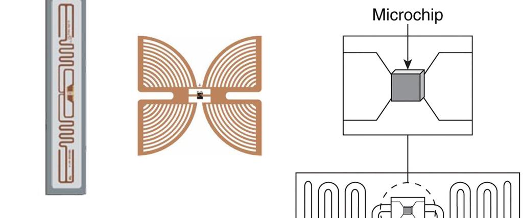
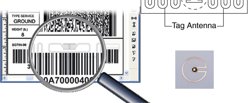
6 Tag Zoo kunr1-6


7 Example of Passive Tag kunr1-7
8 IOT Semi-passive Sensors µc Memory Sensor kunr1-8


9 Example of Semi-passive Sensor Rechargeable Battery Sensor Part Antenna Passive RFID kunr kunr1-9
 Path Loss 49 db @ 8 m Gain = 7 db Receiver")
 Path Loss 49 db @ 8 m -22 dbm (6 µw) backscatter signal Reality: Additionally orientation losses, system losses, fading,")
10 Passive UHF RFID Link Budget: - Read Tags up to 8m Distance - Limited by Tag Power Consumption Pt Gt Gr λ Pr = 2 2 (4π) d L 2 * EPC Class 1 Gen dbm - 16 dbm received at tag * S/N = 35 db + 33 dbm (2 W) Path Loss 49 8 m Gain = 7 db Receiver Noise: -99 dbm (F = 25 db, B = 100 khz) - 71 dbm (0.1 nw) Path Loss 49 8 m -22 dbm (6 µw) backscatter signal Reality: Additionally orientation losses, system losses, fading, n > 2... Additional noise sources, amplitude phase, TX to RX coupling kunr1-10

 Reader (Lesegerät)")
11 RFID EPC Gen2 UHF Reader 10 mm TX antenna modulation switch power amp RX antenna RADIATING signal processor synthesizer I Q 120 mm D A filter direct conversion receiver Passive Tag (Etikette) Reader (Lesegerät) kunr1-11
 Architektur DSP FPGA ADC")

12 RFID: 4 Watt EPC Gen2 Reader Software Defined Radio (SDR) Architektur DSP FPGA ADC DAC Synthesizer Xscale DC-RX TX Amp Supply Circulator Ethernet USB RS232 4 Antenna Ports kunr1-12
13 SDR: UHF RFID Reader RISC Processor - MAC - Reader Protocol - Interfaces Signal Processing - Sample Level on FPGA - Symbol Level on DSP - Air Protocol on DSP UHF Frontend - Direct Conversion Receiver - Carrier Suppression - Multi Antenna kunr1-13


14 Tag to Reader: Sub Carrier Encoding ASK or PSK modulation: 5 kbps < data rate < 640 kbps Baseband-FM0 for single reader per frequency channel saves bandwidth Miller sub carrier encoding for dense reader environment no reader - tag collisions if massive filtering is used + FM0 Interrogator commanding Interrogator listening Filter Miller Tag response Frequency kunr1-14
15 European Regulatory ETSI Channel BW = 200 khz 4 high power channels allowed within EU, ERP 4 W each Concurrent operation in close proximity of readers on same channel needed kunr1-15


16 Example: Dock Door Application Reader related risks Mutual interference among readers: Co-channel interference Adjacent channel interferences Multi Carrier and Miller Coding Organize frequency plan D = 4 m adjacent interferer distance D = 9 m co-channel interferer distance Nr. 7 an d 13 assumed to be blocked by interferer kunr1-16


17 Example: Dock Door Application Metro Germany Logistic Centre Swiss Post Härkingen Metro RFID Dock Door Portal Swiss Post Härkingen kunr1-17
18 Filtering UHF RFID Reader (Europe) Interrogator commanding Interrogator listening HP Filter Filter LP Tag response -240 khz DC 240 khz ± 80 ± 80 Frequency EPC Gen2/ Europe: Subcarrier and data rates are extremely variable! kunr1-18


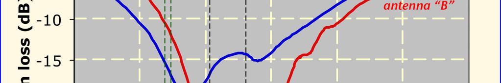
19 Interfering Power Levels Interferer has advantage over victim tag because its signal decreases with 1/d 2 versus 1/d 4 of the passive tag P Rx,dBm = P EIRP,dBm + G Rx, dbi + 20 log 4 λ π D First Spec Assumption: Adj. carrier level = weakest tag level fp = 320 khz, Ap = 3 db fs = 600 khz, As = 62 db 7 th order CH plus HP 2.O. against DC from own carrier kunr1-19


20 1 st idea: Integrated Active Filter I-,Q-Filter: N = 6, Butterworth unfortunately above 1 MHz Attenuation unsufficient IM3 spectral lines too high, as IM is generated mainly by interferers kunr1-20

21 What s Possible 2017: ADRF6518 Matched pair of programmable filters Continuous gain control range: 72 db Digital gain control: 30 db Filter bypass mode bandwidth (BW) 3 db small signal bandwidth: 1100 MHz, VGA2 and VGA3 21 db/12 db 6-pole Butterworth filter: 1 MHz to 63 MHz in 1 MHz steps, 0.5 db corner frequency IMD3: >65 dbc for 1.5 V p-p output
22 I-/Q- Basisband Filter 2 nd idea: Active RC failed due to GBP (Qmax 320 khz) I IN I OUT 3 rd idea: LC Filter Design selected Noise free No IM 7. Order LP 3 db Chebishev f c = 320 khz Q Q kunr1-22
23 I-/Q- Basisband Filter Carrier CH1 Tag Carrier CH2 LP Design shows most hardest Spec kunr1-23
24 Modern Characterization of ADC: Dynamic Range, Spurious ADC Speed and power constraints: 14 Bit ADC 5 Msps Fading Marge 10 db Max input level: -10 dbfs Tag signal dynamic range: 40 db Nr.of Bits for Min input level: 4 Bit Spurious min 10 db lower -10 dbfs Tag Dynamic Range 40 db SFDR -84 dbfs Min SNR 4 Bit -50 dbfs -74 dbfs kunr1-24
25 Selected ADC SNR SFDR Integrated dual 14-bit ADC Single 3 V supply operation (2.7 V to 3.6 V) SNR = 74 db (to Nyquist, AD ) SFDR = 86 dbc (to Nyquist, AD ) Low power: 90 mw/channel at 20 MSPS Nyquist Example: fs = 5 Msps, FFT 16k-point no averaging kunr1-25
26 Modern Characterization of ADC: Noise Floor ADC DAC SNR Noise Density [dbc/hz]: Measured Value - 10 log (BW) Noise für SNR: Noise Density + 10 log(f s /2) Noise Density [dbc/hz]: FFT Floor 10 log (f s /M) kunr1-26
27 Synthesizer for European (868 MHz, 4 channels) and US Regulations ( MHz) PLL: Modulus Divider Phase/Frequency Detector Charge Pump VCO MHZ Clock Buffer TCXO 20 MHz Loop Filter 3. Ordnung B = 4 khz kunr1-27
28 I/Q - Downconversion MAMXSS0011 uses FET Switch for mixing High IIP3: 20 dbm I Mixer 90 0 Phase Shifter Q Mixer 3 db Power Splitter Interrogator commanding Interrogator listening Filter Mixes the User Carrier In CHx to DC Tag response DC Frequency kunr1-28
29 Further Challenges for Reader Tag response in Dense Reader Mode is received in channel adjacent to carrier While transmitting, readers are emitting noise to this adjacent channels where the tag response is received Noise from several modulated readers sum up and interfere with weak tag responses Min. distance d between co-channel operated readers must be respected Lit.: ETSI EN V1.2.1 kunr1-29


30 UHF Signal Propagation Material Orientation Test fixture with 7 3 Gen2 tags, equally spaced in air medium Target read time: < 1 second kunr1-30


31 UHF Signal Propagation Multi-path reflections from metal (reinforcing in floors/ dock levellers and other objects), cause nulls and peaks that get worse with distance from the antenna. height Reader -3 dbm -14 dbm kunr1-31

32 λ π π λ = d h h 2 sin d ) (4 G G P 4 P r t r t t r Fading - Problem in Passive RFID Simple 2-Ray Model RFID: Carrier only Slow Flat Fading Channel kunr1-32
Definition of RF-ID. Lecture on RF-IDs
 Definition of RF-ID RF-ID: Radio Frequency Identification. Indicates the use of Electromagnetic waves to detect and identify TAGS (i.e. labels) purposely attached to objects Basic components (2) Interrogator
RFID Reader Frontends for a Dual-Frequency (13 MHz and 868 MHz) Rapid Prototyping Environment
 Rapid Prototyping Environment") RFID Reader Frontends for a Dual-Frequency (13 MHz and 868 MHz) Rapid Prototyping Environment Robert Langwieser, Michael Fischer and Prof. Dr. Arpad L. Scholtz Vienna University of Technology www.tuwien.ac.at
RFID Reader Frontends for a Dual-Frequency (13 MHz and 868 MHz) Rapid Prototyping Environment Robert Langwieser, Michael Fischer and Prof. Dr. Arpad L. Scholtz Vienna University of Technology www.tuwien.ac.at
Course Project. Project team forming deadline has passed Project teams will be announced soon Next step: project proposal presentation
 Course Project Project team forming deadline has passed Project teams will be announced soon Next step: project proposal presentation Presentation slides and one-page proposal document are due on Jan 30
Fully integrated UHF RFID mobile reader with power amplifiers using System-in-Package (SiP)
") Fully integrated UHF RFID mobile reader with power amplifiers using System-in-Package (SiP) Hyemin Yang 1, Jongmoon Kim 2, Franklin Bien 3, and Jongsoo Lee 1a) 1 School of Information and Communications,
Fully integrated UHF RFID mobile reader with power amplifiers using System-in-Package (SiP) Hyemin Yang 1, Jongmoon Kim 2, Franklin Bien 3, and Jongsoo Lee 1a) 1 School of Information and Communications,
FCC and ETSI Requirements for Short-Range UHF ASK- Modulated Transmitters
 From December 2005 High Frequency Electronics Copyright 2005 Summit Technical Media FCC and ETSI Requirements for Short-Range UHF ASK- Modulated Transmitters By Larry Burgess Maxim Integrated Products
HF-RFID. References. School of Engineering
 HF-RFID MSE, HF-RFID, 1 References [1] Klaus Finkenzeller, RFID-Handbuch, 5. Auflage, Hanser, 2008. [2] R. Küng, M. Rupf, RFID-Blockkurs, ergänzende MSE-Veranstaltung, ZHAW, 2011. Kontakt: ZHAW Zürcher
Keysight Technologies
 Keysight Technologies Generating Signals Basic CW signal Block diagram Applications Analog Modulation Types of analog modulation Block diagram Applications Digital Modulation Overview of IQ modulation
Physics of RFID. Pawel Waszczur McMaster RFID Applications Lab McMaster University
 1 Physics of RFID Pawel Waszczur McMaster RFID Applications Lab McMaster University 2 Agenda Radio Waves Active vs. Passive Near field vs. Far field Behavior of UHF fields Modulation & Signal Coding 3
ADI 2006 RF Seminar. Chapter II RF/IF Components and Specifications for Receivers
 ADI 2006 RF Seminar Chapter II RF/IF Components and Specifications for Receivers 1 RF/IF Components and Specifications for Receivers Fixed Gain and Variable Gain Amplifiers IQ Demodulators Analog-to-Digital
Evaluation of the Effect of Gen2 Parameters on the UHF RFID Tag Read Rate
 International Journal of Latest Trends in Computing (E-ISSN: 2045-5364) 160 Evaluation of the Effect of Gen2 Parameters on the UHF RFID Tag Read Rate Jussi Nummela, Petri Oksa, Leena Ukkonen and Lauri
Analysis and Simulation of UHF RFID System
 ICSP006 Proceedings Analysis and Simulation of UHF RFID System Jin Li, Cheng Tao Modern Telecommunication Institute, Beijing Jiaotong University, Beijing 00044, P. R. China Email: lijin3@63.com Abstract
Understanding RF and Microwave Analysis Basics
 Understanding RF and Microwave Analysis Basics Kimberly Cassacia Product Line Brand Manager Keysight Technologies Agenda µw Analysis Basics Page 2 RF Signal Analyzer Overview & Basic Settings Overview
TSEK02: Radio Electronics Lecture 8: RX Nonlinearity Issues, Demodulation. Ted Johansson, EKS, ISY
 TSEK02: Radio Electronics Lecture 8: RX Nonlinearity Issues, Demodulation Ted Johansson, EKS, ISY RX Nonlinearity Issues: 2.2, 2.4 Demodulation: not in the book 2 RX nonlinearities System Nonlinearity
Reconfigurable 6 GHz Vector Signal Transceiver with I/Q Interface
 SPECIFICATIONS PXIe-5645 Reconfigurable 6 GHz Vector Signal Transceiver with I/Q Interface Contents Definitions...2 Conditions... 3 Frequency...4 Frequency Settling Time... 4 Internal Frequency Reference...
SC5407A/SC5408A 100 khz to 6 GHz RF Upconverter. Datasheet. Rev SignalCore, Inc.
 SC5407A/SC5408A 100 khz to 6 GHz RF Upconverter Datasheet Rev 1.2 2017 SignalCore, Inc. support@signalcore.com P R O D U C T S P E C I F I C A T I O N S Definition of Terms The following terms are used
Specifications and Interfaces
 Specifications and Interfaces Crimson TNG is a wide band, high gain, direct conversion quadrature transceiver and signal processing platform. Using analogue and digital conversion, it is capable of processing
Backscatter and Ambient Communication. Yifei Liu
 Backscatter and Ambient Communication Yifei Liu Outline 1. Introduction 2. Ambient Backscatter 3. WiFi Backscatter 4. Passive WiFi Backscatter Outline 1. Introduction 2. Ambient Backscatter 3. WiFi Backscatter
LNS ultra low phase noise Synthesizer 8 MHz to 18 GHz
 LNS ultra low phase noise Synthesizer 8 MHz to 18 GHz Datasheet The LNS is an easy to use 18 GHz synthesizer that exhibits outstanding phase noise and jitter performance in a 3U rack mountable chassis.
TSEK38 Radio Frequency Transceiver Design: Project work B
 TSEK38 Project Work: Task specification A 1(15) TSEK38 Radio Frequency Transceiver Design: Project work B Course home page: Course responsible: http://www.isy.liu.se/en/edu/kurs/tsek38/ Ted Johansson (ted.johansson@liu.se)
Does The Radio Even Matter? - Transceiver Characterization Testing Framework
 Does The Radio Even Matter? - Transceiver Characterization Testing Framework TRAVIS COLLINS, PHD ROBIN GETZ 2017 Analog Devices, Inc. All rights reserved. 1 Which cost least? 3 2017 Analog Devices, Inc.
Today s mobile devices
 PAGE 1 NOVEMBER 2013 Highly Integrated, High Performance Microwave Radio IC Chipsets cover 6-42 GHz Bands Complete Upconversion & Downconversion Chipsets for Microwave Point-to-Point Outdoor Units (ODUs)
SC5306B 1 MHz to 3.9 GHz RF Downconverter Core Module. Datasheet SignalCore, Inc.
 SC5306B 1 MHz to 3.9 GHz RF Downconverter Core Module Datasheet 2015 SignalCore, Inc. support@signalcore.com SC5306B S PECIFICATIONS Definition of Terms The following terms are used throughout this datasheet
Reference Clock Distribution for a 325MHz IF Sampling System with over 30MHz Bandwidth, 64dB SNR and 80dB SFDR
 Reference Clock Distribution for a 325MHz IF Sampling System with over 30MHz Bandwidth, 64dB SNR and 80dB SFDR Michel Azarian Clock jitter introduced in an RF receiver through reference clock buffering
A UHF Radio Frequency Identification (RFID) System for Healthcare: Design and Implementation
 System for Healthcare: Design and Implementation") A UHF Radio Frequency Identification (RFID) System for Healthcare: Design and Implementation A. C. Polycarpou 1, G. Gregoriou 1, A. Dimitriou 2, A. Bletsas 3, J. N. Sahalos 1,2 Cyprus Academic Research
A UHF Radio Frequency Identification (RFID) System for Healthcare: Design and Implementation A. C. Polycarpou 1, G. Gregoriou 1, A. Dimitriou 2, A. Bletsas 3, J. N. Sahalos 1,2 Cyprus Academic Research
APPLICATION NOTE 3942 Optimize the Buffer Amplifier/ADC Connection
 Maxim > Design Support > Technical Documents > Application Notes > Communications Circuits > APP 3942 Maxim > Design Support > Technical Documents > Application Notes > High-Speed Interconnect > APP 3942
An All CMOS, 2.4 GHz, Fully Adaptive, Scalable, Frequency Hopped Transceiver
 An All CMOS, 2.4 GHz, Fully Adaptive, Scalable, Frequency Hopped Transceiver Farbod Behbahani John Leete Alexandre Kral Shahrzad Tadjpour Karapet Khanoyan Paul J. Chang Hooman Darabi Maryam Rofougaran
PROPAGATION CHANNEL EMULATOR : ECP
 PROPAGATION CHANNEL EMULATOR : ECP The ECP (Propagation Channel Emulator) synthesizes the principal phenomena of propagation occurring on RF signal links between earth and space. Developed by the R&D laboratory,
Chapter 4 Radio Communication Basics
 Chapter 4 Radio Communication Basics Chapter 4 Radio Communication Basics RF Signal Propagation and Reception Basics and Keywords Transmitter Power and Receiver Sensitivity Power - antenna gain: G TX,
Receiver Architecture
 Receiver Architecture Receiver basics Channel selection why not at RF? BPF first or LNA first? Direct digitization of RF signal Receiver architectures Sub-sampling receiver noise problem Heterodyne receiver
Supplemental Slides: MIMO Testbed Development at the MPRG Lab
 Supplemental Slides: MIMO Testbed Development at the MPRG Lab Raqibul Mostafa Jeffrey H. Reed Slide 1 Overview Space Time Coding (STC) Overview Virginia Tech Space Time Adaptive Radio (VT-STAR) description:
PTX-0350 RF UPCONVERTER, MHz
 PTX-0350 RF UPCONVERTER, 300 5000 MHz OPERATING MODES I/Q upconverter RF = LO + IF upconverter RF = LO - IF upconverter Synthesizer 10 MHz REFERENCE INPUT/OUTPUT EXTERNAL LOCAL OSCILLATOR INPUT I/Q BASEBAND
Module 8 Theory. dbs AM Detector Ring Modulator Receiver Chain. Functional Blocks Parameters. IRTS Region 4
 Module 8 Theory dbs AM Detector Ring Modulator Receiver Chain Functional Blocks Parameters Decibel (db) The term db or decibel is a relative unit of measurement used frequently in electronic communications
TSEK38: Radio Frequency Transceiver Design Lecture 7: Receiver Synthesis (II)
") TSEK38: Radio Frequency Transceiver Design Lecture 7: Receiver Synthesis (II) Ted Johansson, ISY ted.johansson@liu.se Systematic Receiver Synthesis (II) 4.3 Intermodulation characteristics Phase noise
TSEK38: Radio Frequency Transceiver Design Lecture 7: Receiver Synthesis (II) Ted Johansson, ISY ted.johansson@liu.se Systematic Receiver Synthesis (II) 4.3 Intermodulation characteristics Phase noise
SC5307A/SC5308A 100 khz to 6 GHz RF Downconverter. Datasheet SignalCore, Inc.
 SC5307A/SC5308A 100 khz to 6 GHz RF Downconverter Datasheet 2017 SignalCore, Inc. support@signalcore.com P RODUCT S PECIFICATIONS Definition of Terms The following terms are used throughout this datasheet
The LoRa Protocol. Overview. Interference Immunity. Technical Brief AN205 Rev A0
 Technical Brief AN205 Rev A0 The LoRa Protocol By John Sonnenberg Raveon Technologies Corp Overview The LoRa (short for Long Range) modulation scheme is a modulation technique combined with a data encoding
RF/IF Terminology and Specs
 RF/IF Terminology and Specs Contributors: Brad Brannon John Greichen Leo McHugh Eamon Nash Eberhard Brunner 1 Terminology LNA - Low-Noise Amplifier. A specialized amplifier to boost the very small received
Radio-Frequency Conversion and Synthesis (for a 115mW GPS Receiver)
") Radio-Frequency Conversion and Synthesis (for a 115mW GPS Receiver) Arvin Shahani Stanford University Overview GPS Overview Frequency Conversion Frequency Synthesis Conclusion GPS Overview: Signal Structure
Radio-Frequency Conversion and Synthesis (for a 115mW GPS Receiver) Arvin Shahani Stanford University Overview GPS Overview Frequency Conversion Frequency Synthesis Conclusion GPS Overview: Signal Structure
TSEK02: Radio Electronics Lecture 8: RX Nonlinearity Issues, Demodulation. Ted Johansson, EKS, ISY
 TSEK02: Radio Electronics Lecture 8: RX Nonlinearity Issues, Demodulation Ted Johansson, EKS, ISY 2 RX Nonlinearity Issues, Demodulation RX nonlinearities (parts of 2.2) System Nonlinearity Sensitivity
UHF-Technology. Vorlesung RFID Systems Benno Flecker, Michael Gebhart TU Graz, Sommersemester 2016
 UHF-Technology Vorlesung RFID Systems Benno Flecker, Michael Gebhart TU Graz, Sommersemester 2016 RFID System A traditional passive label (tag) is queried and it responds with it s ID accordingly. Power
RFID UHF pour l'identification et la traçabilité des objets. Jean-Marc Laheurte Professeur à l Université Paris-Est
 RFID UHF pour l'identification et la traçabilité des objets Jean-Marc Laheurte Professeur à l Université Paris-Est Séminaire TELECOM ParisTech du 10 janvier 2013 1 Agenda Generalities and Principles HF
Using Passive UHF RFID to Create The Intelligent Airport
 Using Passive UHF RFID to Create Intelligent S. Sabesan, M. J. Crisp, R. V. Penty and I. H. White Photonics Communications Group Department of Engineering University of Cambridge 9 J J Thomson Avenue Cambridge
CLOUDSDR RFSPACE #CONNECTED SOFTWARE DEFINED RADIO. final design might vary without notice
 CLOUDSDR #CONNECTED SOFTWARE DEFINED RADIO final design might vary without notice 1 - PRELIMINARY SPECIFICATIONS http://www.rfspace.com v0.1 RFSPACE CloudSDR CLOUDSDR INTRODUCTION The RFSPACE CloudSDR
NOISE, INTERFERENCE, & DATA RATES
 COMP 635: WIRELESS NETWORKS NOISE, INTERFERENCE, & DATA RATES Jasleen Kaur Fall 2015 1 Power Terminology db Power expressed relative to reference level (P 0 ) = 10 log 10 (P signal / P 0 ) J : Can conveniently
Final Project Introduction to RFID (Radio Frequency IDentification) Andreas G. Andreou
 Andreas G. Andreou") Final Project Introduction to RFID (Radio Frequency IDentification) Andreas G. Andreou Radio Frequency IDentification Frequency Distance LF 125khz Few cm HF 13.56Mhz 1m Example Application Auto- Immobilizer
Final Project Introduction to RFID (Radio Frequency IDentification) Andreas G. Andreou Radio Frequency IDentification Frequency Distance LF 125khz Few cm HF 13.56Mhz 1m Example Application Auto- Immobilizer
NXDN Signal and Interference Contour Requirements An Empirical Study
 NXDN Signal and Interference Contour Requirements An Empirical Study Icom America Engineering December 2007 Contents Introduction Results Analysis Appendix A. Test Equipment Appendix B. Test Methodology
Scalable Front-End Digital Signal Processing for a Phased Array Radar Demonstrator. International Radar Symposium 2012 Warsaw, 24 May 2012
 Scalable Front-End Digital Signal Processing for a Phased Array Radar Demonstrator F. Winterstein, G. Sessler, M. Montagna, M. Mendijur, G. Dauron, PM. Besso International Radar Symposium 2012 Warsaw,
Propagation Channel Emulator ECP-70
 1 product description The ECP (Propagation Channel Emulator 70) synthesizes the principal phenomena of propagation occurring on RF signal links between earth and space. Developed by the R&D laboratory,
Impact of mm-wave Range and Large Bandwidth on RF System Design. R&S Taiwan Feiyu Chen
 Impact of mm-wave Range and Large Bandwidth on RF System Design R&S Taiwan Feiyu Chen Simplified RF Architecture ı ITU Band 11 (Extremely High Frequency) 30 to 300 GHz ı Wavelength range 1 to 10 mm Digital
Technician License Course Chapter 3 Types of Radios and Radio Circuits. Module 7
 Technician License Course Chapter 3 Types of Radios and Radio Circuits Module 7 Radio Block Diagrams Radio Circuits can be shown as functional blocks connected together. Knowing the description of common
Application Note: IQ Filtering in an RFID Reader Using Anadigm Integrated circuits,
 Application Note: IQ Filtering in an RFID Reader Using Anadigm Integrated circuits, Rev: 1.0.3 Date: 3 rd April 2006 We call this multi-chip circuit solution RangeMaster3, It uses Anadigm s. RangeMaster2
A 1.9GHz Single-Chip CMOS PHS Cellphone
 A 1.9GHz Single-Chip CMOS PHS Cellphone IEEE JSSC, Vol. 41, No.12, December 2006 William Si, Srenik Mehta, Hirad Samavati, Manolis Terrovitis, Michael Mack, Keith Onodera, Steve Jen, Susan Luschas, Justin
CDMA Principle and Measurement
 CDMA Principle and Measurement Concepts of CDMA CDMA Key Technologies CDMA Air Interface CDMA Measurement Basic Agilent Restricted Page 1 Cellular Access Methods Power Time Power Time FDMA Frequency Power
Vehicle Networks. Wireless communication basics. Univ.-Prof. Dr. Thomas Strang, Dipl.-Inform. Matthias Röckl
 Vehicle Networks Wireless communication basics Univ.-Prof. Dr. Thomas Strang, Dipl.-Inform. Matthias Röckl Outline Wireless Signal Propagation Electro-magnetic waves Signal impairments Attenuation Distortion
Politecnico di Milano Advanced Network Technologies Laboratory. Radio Frequency Identification
 Politecnico di Milano Advanced Network Technologies Laboratory Radio Frequency Identification RFID in Nutshell o To Enhance the concept of bar-codes for faster identification of assets (goods, people,
Noise and Interference Limited Systems
 Chapter 3 Noise and Interference Limited Systems 47 Basics of link budgets Link budgets show how different components and propagation processes influence the available SNR Link budgets can be used to compute
Preliminary features of the SDR-X receiver SDR-X , PowerSDR Winrad Winrad DDS SFDR SFDR AD995 AD99 1
 Preliminary features of the SDR-X receiver The SDR-X receiver, in its full version is capable of continuously tuning the entire HF spectrum, 6m ( 50-52 MHz) band included. SSB, AM etc. demodulation, bandpass
ETSI Standards and the Measurement of RF Conducted Output Power of Wi-Fi ac Signals
 ETSI Standards and the Measurement of RF Conducted Output Power of Wi-Fi 802.11ac Signals Introduction The European Telecommunications Standards Institute (ETSI) have recently introduced a revised set
SiNANO-NEREID Workshop:
 SiNANO-NEREID Workshop: Towards a new NanoElectronics Roadmap for Europe Leuven, September 11 th, 2017 WP3/Task 3.2 Connectivity RF and mmw Design Outline Connectivity, what connectivity? High data rates
RSE02401/00 24 GHz Radar Sensor
 General description The RSE02401/00 is a fully integrated K-band FMCW radar sensor. It utilizes packaged low-cost components, enabling low unit prices and high volumes, using SMT assembly technology, with
Lecture 5 Transmission
 Lecture 5 Transmission David Andersen Department of Computer Science Carnegie Mellon University 15-441 Networking, Spring 2005 http://www.cs.cmu.edu/~srini/15-441/s05 1 Physical and Datalink Layers: 3
Bits to Antenna and Back
 The World Leader in High Performance Signal Processing Solutions Bits to Antenna and Back June 2012 Larry Hawkins ADL5324 400 4000 MHz Broadband ½ W RF Driver Amplifier KEY SPECIFICATIONS (5 V) Frequency
RFID Systems: Radio Architecture
 RFID Systems: Radio Architecture 1 A discussion of radio architecture and RFID. What are the critical pieces? Familiarity with how radio and especially RFID radios are designed will allow you to make correct
Solution: NF=6 db, B=2.1 GHz, SNR min =7dB T=290 k, P in,1db = 10.5 dbm
 Consider a receiver with a noise figure of 6 db and a bandwidth of 2.1 GHz operating at room temperature. The input 1-dB compression point is 10.5 dbm and the detector at receiver output requires a minimum
RFID. Contents and form. Petr Bureš, Faculty of transportation sciences Czech technical university in Prague
 RFID Contents and form Petr Bureš, bures@fd.cvut.cz Faculty of transportation sciences Czech technical university in Prague RFID considerations Critical performance variables in an RFID system are the
Research and Development Activities in RF and Analog IC Design. RFIC Building Blocks. Single-Chip Transceiver Systems (I) Howard Luong
 Howard Luong") Research and Development Activities in RF and Analog IC Design Howard Luong Analog Research Laboratory Department of Electrical and Electronic Engineering Hong Kong University of Science and Technology
Research and Development Activities in RF and Analog IC Design Howard Luong Analog Research Laboratory Department of Electrical and Electronic Engineering Hong Kong University of Science and Technology
RF System Aspects for SDR. A Tutorial. Dr. Ruediger Leschhorn, Rohde & Schwarz 29. November 2011
 RF System Aspects for SDR A Tutorial Dr. Ruediger Leschhorn, Rohde & Schwarz 29. November 2011 Content Radio System Some Basics Link Budget Cosite Examples Desensitization Blocking, Transmitter Noise,
Nutaq Radio420X Multimode SDR FMC RF transceiver PRODUCT SHEET
 Nutaq Radio420X Multimode SDR FMC RF transceiver PRODUCT SHEET RoHS QUEBEC I MONTREAL I NEW YORK I nutaq.com Nutaq Radio420X SISO, dual-band and 2x2 MIMO RF transceivers Wide frequency range 300 MHz 3
ISSCC 2006 / SESSION 33 / MOBILE TV / 33.4
 33.4 A Dual-Channel Direct-Conversion CMOS Receiver for Mobile Multimedia Broadcasting Vincenzo Peluso, Yang Xu, Peter Gazzerro, Yiwu Tang, Li Liu, Zhenbiao Li, Wei Xiong, Charles Persico Qualcomm, San
Wireless Technology for Aerospace Applications. June 3 rd, 2012
 Wireless Technology for Aerospace Applications June 3 rd, 2012 OUTLINE The case for wireless in aircraft and aerospace applications System level limits of wireless technology Security Power (self powered,
What s Behind 5G Wireless Communications?
 What s Behind 5G Wireless Communications? Marc Barberis 2015 The MathWorks, Inc. 1 Agenda 5G goals and requirements Modeling and simulating key 5G technologies Release 15: Enhanced Mobile Broadband IoT
Wireless Communication
 Wireless Communication Systems @CS.NCTU Lecture 14: Full-Duplex Communications Instructor: Kate Ching-Ju Lin ( 林靖茹 ) 1 Outline What s full-duplex Self-Interference Cancellation Full-duplex and Half-duplex
Basics of RFID technology Thomas Holtstiege Technical Manager EECC. October 2009
 Basics of RFID technology Thomas Holtstiege Technical Manager EECC October 2009 About the European EPC Competence Center (EECC) First European EPCglobal accredited performance test center Active since
Enhancing Analog Signal Generation by Digital Channel Using Pulse-Width Modulation
 Enhancing Analog Signal Generation by Digital Channel Using Pulse-Width Modulation Angelo Zucchetti Advantest angelo.zucchetti@advantest.com Introduction Presented in this article is a technique for generating
Data Sheet SC5317 & SC5318A. 6 GHz to 26.5 GHz RF Downconverter SignalCore, Inc. All Rights Reserved
 Data Sheet SC5317 & SC5318A 6 GHz to 26.5 GHz RF Downconverter www.signalcore.com 2018 SignalCore, Inc. All Rights Reserved Definition of Terms 1 Table of Contents 1. Definition of Terms... 2 2. Description...
THE BASICS OF RADIO SYSTEM DESIGN
 THE BASICS OF RADIO SYSTEM DESIGN Mark Hunter * Abstract This paper is intended to give an overview of the design of radio transceivers to the engineer new to the field. It is shown how the requirements
Development of Standard Time and Frequency Service using Low Frequency in Korea
 Development of Standard Time and Frequency Service using Low Frequency in Korea Center for Time & Frequency Y.K. Lee, D.H. Yu, S.H. Yang, J.K. Lee, S.W. Hwang Contents Introductions LF applications, research
Nutaq Radio420X I MONTREAL I NEW YORK I. Multimode SDR FMC RF transceiver PRODUCT SHEET. RoHS. nutaq.com QUEBEC
 Nutaq Radio420X Multimode SDR FMC RF transceiver PRODUCT SHEET RoHS QUEBEC I MONTREAL I NEW YORK I nutaq.com Nutaq Radio420X SISO, dual-band and 2x2 MIMO RF transceivers Wide frequency range 300 MHz 3.8
A new generation Cartesian loop transmitter for fl exible radio solutions
 Electronics Technical A new generation Cartesian loop transmitter for fl exible radio solutions by C.N. Wilson and J.M. Gibbins, Applied Technology, UK The concept software defined radio (SDR) is much
ISSCC 2006 / SESSION 20 / WLAN/WPAN / 20.5
 20.5 An Ultra-Low Power 2.4GHz RF Transceiver for Wireless Sensor Networks in 0.13µm CMOS with 400mV Supply and an Integrated Passive RX Front-End Ben W. Cook, Axel D. Berny, Alyosha Molnar, Steven Lanzisera,
RFID (Radio Frequency Identification) Overview
 Overview") RFID (Radio Frequency Identification) Overview António Grilo Courtesy: Greg Leeming, INTEL Sridhar Iyer, ITT Bombay Radio Frequency Identification Power from RF field Reader Antenna Reader->Tag Commands
RFID (Radio Frequency Identification) Overview António Grilo Courtesy: Greg Leeming, INTEL Sridhar Iyer, ITT Bombay Radio Frequency Identification Power from RF field Reader Antenna Reader->Tag Commands
An Empirical Study of UHF RFID Performance. Michael Buettner and David Wetherall Presented by Qian (Steve) He CS Prof.
 He CS Prof.") An Empirical Study of UHF RFID Performance Michael Buettner and David Wetherall Presented by Qian (Steve) He CS 577 - Prof. Bob Kinicki Overview Introduction Background Knowledge Methodology and Tools
An Empirical Study of UHF RFID Performance Michael Buettner and David Wetherall Presented by Qian (Steve) He CS 577 - Prof. Bob Kinicki Overview Introduction Background Knowledge Methodology and Tools
Wirelessly Powered Sensor Transponder for UHF RFID
 Wirelessly Powered Sensor Transponder for UHF RFID In: Proceedings of Transducers & Eurosensors 07 Conference. Lyon, France, June 10 14, 2007, pp. 73 76. 2007 IEEE. Reprinted with permission from the publisher.
Wavedancer A new ultra low power ISM band transceiver RFIC
 Wavedancer 400 - A new ultra low power ISM band transceiver RFIC R.W.S. Harrison, Dr. M. Hickson Roke Manor Research Ltd, Old Salisbury Lane, Romsey, Hampshire, SO51 0ZN. e-mail: roscoe.harrison@roke.co.uk
6.976 High Speed Communication Circuits and Systems Lecture 20 Performance Measures of Wireless Communication
 6.976 High Speed Communication Circuits and Systems Lecture 20 Performance Measures of Wireless Communication Michael Perrott Massachusetts Institute of Technology Copyright 2003 by Michael H. Perrott
ADJACENT BAND COMPATIBILITY BETWEEN GSM AND TETRA MOBILE SERVICES AT 915 MHz
 Electronic Communications Committee (ECC) within the European Conference of Postal and Telecommunications Administrations (CEPT) ADJACENT BAND COMPATIBILITY BETWEEN GSM AND TETRA MOBILE SERVICES AT 915
CS263: Wireless Communications and Sensor Networks
 CS263: Wireless Communications and Sensor Networks Matt Welsh Lecture 3: Antennas, Propagation, and Spread Spectrum September 30, 2004 2004 Matt Welsh Harvard University 1 Today's Lecture Antennas and
Sigfox RF & Protocol Test Plan for RC1-UDL-ENC-MONARCH
 Version 3.8.0 September 14, 2018 Sigfox RF & Protocol Test Plan for RC1-UDL-ENC-MONARCH Public Use Note: Only the last version of this document available on the Sigfox web sites is official and applicable.
TSEK38: Radio Frequency Transceiver Design Lecture 3: Superheterodyne TRX design
 TSEK38: Radio Frequency Transceiver Design Lecture 3: Superheterodyne TRX design Ted Johansson, ISY ted.johansson@liu.se 2 Outline of lecture 3 Introduction RF TRX architectures (3) Superheterodyne architecture
RFID/NFC TECHNOLOGY. With emphasis on physical layer. Ali Zaher Oslo
 RFID/NFC TECHNOLOGY With emphasis on physical layer Ali Zaher Oslo 28.09.2012 CONTENTS List of abbreviations. RFID Definition. RFID Coupling. NFC. RFID Physical Model. NFC Physical Model. My work. 2 LIST
Project: IEEE P Working Group for Wireless Personal Area Networks N
 Project: IEEE P802.15 Working Group for Wireless Personal Area Networks N (WPANs( WPANs) Title: [Draft PHY Proposal for 60 GHz WPAN] Date Submitted: [11 November, 2005] Source: [Eckhard Grass, Maxim Piz,
SPECIFICATION FREQUENCY RANGE: IBS-6
 IBS Series SYNTHESIZER SPECIFICATION FREQUENCY RANGE: IBS-6 0.1 to 6 GHz IBS-18 2 to 18 GHz IBS-20 0.1 to 20 GHz FEATURES Wide Frequency Bandwidth: 0.1 to 20 GHz Fast Switching Speed: 200 usec, Full Band
IEEE JOURNAL OF SOLID-STATE CIRCUITS, VOL. 43, NO. 3, MARCH
 IEEE JOURNAL OF SOLID-STATE CIRCUITS, VOL. 43, NO. 3, MARCH 2008 729 A Single-Chip CMOS Transceiver for UHF Mobile RFID Reader Ickjin Kwon, Member, IEEE, Yunseong Eo, Member, IEEE, Heemun Bang, Kyudon
ISSCC 2003 / SESSION 20 / WIRELESS LOCAL AREA NETWORKING / PAPER 20.5
 ISSCC 2003 / SESSION 20 / WIRELESS LOCAL AREA NETWORKING / PAPER 20.5 20.5 A 2.4GHz CMOS Transceiver and Baseband Processor Chipset for 802.11b Wireless LAN Application George Chien, Weishi Feng, Yungping
Integrated receivers for mid-band SKA. Suzy Jackson Engineer, Australia Telescope National Facility
 Integrated receivers for mid-band SKA Suzy Jackson Engineer, Australia Telescope National Facility SKADS FP6 Meeting Chateau de Limelette 4-6 November, 2009 Talk overview Mid band SKA receiver challenges
The Friis Transmission Formula
 The Friis Transmission Formula If we assume that the antennas are aligned for maximum transmission and reception, then in free space, P RX = G TXA e P TX 4πr 2 where A e is the receiving aperture of the
Session 3. CMOS RF IC Design Principles
 Session 3 CMOS RF IC Design Principles Session Delivered by: D. Varun 1 Session Topics Standards RF wireless communications Multi standard RF transceivers RF front end architectures Frequency down conversion
Lecture 5 Transmission. Physical and Datalink Layers: 3 Lectures
 Lecture 5 Transmission Peter Steenkiste School of Computer Science Department of Electrical and Computer Engineering Carnegie Mellon University 15-441 Networking, Spring 2004 http://www.cs.cmu.edu/~prs/15-441
WSA5000. Real-Time Spectrum Analyzer (RTSA) 100 khz to 8 GHz / 18 GHz / 27 GHz. Product Brochure and Technical Datasheet Preliminary.
 100 khz to 8 GHz / 18 GHz / 27 GHz. Product Brochure and Technical Datasheet Preliminary.") Product Brochure and Technical Datasheet WSA5000 Real-Time Spectrum Analyzer (RTSA) 100 khz to 8 GHz / 18 GHz / 27 GHz Featuring Real-Time Bandwidth (RTBW) up to 100 MHz Probability of Intercept (POI)
Product Brochure and Technical Datasheet WSA5000 Real-Time Spectrum Analyzer (RTSA) 100 khz to 8 GHz / 18 GHz / 27 GHz Featuring Real-Time Bandwidth (RTBW) up to 100 MHz Probability of Intercept (POI)
DS H01 DIGITAL SYNTHESIZER MODULE SYSTEM SOLUTIONS. Features Applications 174 x 131 x 54 mm. Technical Description
 DS H01 The DS H01 is a high performance dual digital synthesizer with wide output bandwidth specially designed for Defense applications where generation of wideband ultra-low noise signals along with very
RF Basics June 2010 WLS 04
 www.silabs.com RF Basics June 2010 WLS 04 Agenda Basic link parameters Modulation Types Datarate Deviation RX Baseband BW Crystal selection Frequency error compensation Important t radio parameters Regulatory