ECED3204: Microprocessor Part IV--Timer Function
|
|
|
- Jesse Hopkins
- 6 years ago
- Views:
Transcription
1 ECED3204: Microprocessor Part IV--Timer Function Jason J. Gu Department of 1 Outline i. Introduction to the Microcontroller Timer System ii. Overview of the Mega AVR Timer System iii. Timer Clock Source Selection iv. Timer/Counter Operation Modes v. Applications of Each Timer/Counter Operation Mode 2 1
2 Introduction to the Microcontroller Timer System Clock input Supplied from I/O pin: counter Generated from MCU clock circuit: timer mode Using a timer to create time delays Counts up: n-bit timer: counts up from 0 and reaches 2 n 1; overflows and rolls back to 0 Counts down 3 Introduction to the Microcontroller Timer System: Input capture Input capture: involves external signal applied to an input-capture pin (ICP), involve TCNT, ICR. To measure period, width, duty cycle. 4 2
3 Introduction to the Microcontroller Timer System: Output compare Module includes output compare register (OCR), one or more control registers, one or more status registers, and a base timer/counter (TCNT) register. A output compare pin is also provided To use output compare function, we need to take the following action: make a copy of the TCNT register add an appropriate delay count to this copy store the sum in the OCR register. Output compare function is used to generate periodic interrupts, create time delays, trigger events, generate waveforms, etc. 5 Introduction to the Microcontroller Timer System: Pulse-Width Modulation Pulse-Width Modulation (PWM): waveform continues by itself until the duty cycle or period must be changed Implemented through special circuitry added to the timer system so that the CPU only has to set up the duty cycle and period once PWM module consists of an output pin, a timer/counter, a period register, a duty register. There are single slope and dual slope PWM 6 3
4 Introduction to the Microcontroller Timer System (cont d.) 7 Introduction to the Microcontroller Timer System (cont d.) 8 4
5 Overview of the Mega AVR Timer System ATMega640/1280/2560 devices have six timers Timer 0 and 2 are 8-bit timers Timer 1, 3, 4, and 5 are 16-bit timers All timers except Timer2 derive their clock input by dividing the internal CLKI/O by prescaler or from external pin Timer2 derived its clock by dividing one of following three source: CLKI/O, external KHz, external clock to TOSC1 9 Overview of the Mega AVR Timer System Timer 0 and 2 are 8-bit timers Timer 0 has two output-compare units (OC0A and OC0B). Each output compare unit generate PWM output. Timer 0 has three interrupt sources TOV0, OC0A,OC0B Timer 2 is identical to timer 0 except it may also select clock source. Timer 1, 3, 4, and 5 are 16-bit timers Each 16 bit timer has one input capture unit. (ICn,n=1,3,4,5) Three independent output-compare units (OCnA,OCnB,OCnC, n=1,3,4,5) Five interrupt sources TOVn,ICFn,OCFnA,OCFnB,OCFnC (n=1,3,4,5) 10 5


6 Overview of the Mega AVR Timer System Timers pin assignment Timers share the use of signals with other peripheral signals and general I/O pins 11 Overview of the Mega AVR Timer System 12 6
 8-bit timer building blocks Major components: count unit, output-compare unit, and compare match output unit 13 ) 16-bit timer building blocks Major components: count")
7 Overview of the Mega AVR Timer System (cont d.) 8-bit timer building blocks Major components: count unit, output-compare unit, and compare match output unit 13 Overview of the Mega AVR Timer System (cont d.) 16-bit timer building blocks Major components: count unit, input-capture unit, output-compare unit, and compare match output unit 14 7
 15 Timer Clock Source Selection 16")
8 Timer Clock Source Selection Timer/counter: requires a clock input to count Clock source: selected by programming the Timer/Counter control register B (TCCRnB, n = 0,, 5) 15 Timer Clock Source Selection 16 8
9 Timer Clock Source Selection 17 Timer Clock Source Selection 18 9
 and one or two bits in the Timer/Counter control register B (TCCRnB, n = 0,,")
10 Timer Clock Source Selection 19 Timer/Counter Operation Modes Timer/counter (8- or 16-bit) operation modes: normal, CTC, fast PWM, phase-correct PWM, and phaseand-frequency-correct PWM 8-bit timer/counter operation modes Timer operation mode: selected by the Timer/Counter control register A ( TCCRnA, n = 0,, 5) and one or two bits in the Timer/Counter control register B (TCCRnB, n = 0,, 5) 20 10


11 Timer/Counter Operation Modes 21 Timer/Counter Operation Modes 22 11


12 Timer/Counter Operation Modes 23 Timer/Counter Operation Modes 24 12


13 Timer/Counter Operation Modes 25 Timer/Counter Operation Modes 26 13
14 Timer/Counter Operation Modes 27 Timer/Counter Operation Modes (cont d.) 16-bit timer/counter operation modes Refer to Table 11.6 Selected by programming the GMn3:WGMn2 bits of the Timer/Counter control register B (TCCRnB, n = 1, 3, 4, or 5) together with the WGMn1:WGMn0 bits of the Timer/Counter control register A (TCCRnA, n = 1, 3, 4, 5) 16 bit timer and output compare register are divided into high byte (TCNTnH, OCRnxH) and low byte (TCNTnL, OCRnxL). read access start from low byte, write access start from the high byte


15 Timer/Counter Operation Modes (cont d.) 29 Timer/Counter Operation Modes (cont d.) 30 15

 31 ) 32 16")

16 Timer/Counter Operation Modes (cont d.) 31 Timer/Counter Operation Modes (cont d.) 32 16


17 Timer/Counter Operation Modes (cont d.) 33 Timer/Counter Operation Modes (cont d.) 34 17
 35 Applications of Each Timer/Counter Operation Mode Timer/counter uses: create time delay, generate waveforms, and measure signal")
18 Timer/Counter Operation Modes (cont d.) 35 Applications of Each Timer/Counter Operation Mode Timer/counter uses: create time delay, generate waveforms, and measure signal parameters Five operation mode Normal CTC Fast PWM Phase-correct PWM Phase and-frequency-correct PWM 36 18
19 Using the Timer Normal Mode Timer counts up from 0 to the TOP value, rolls over to 0, and then counts up again. TOVn is set to 1 when the timer rolls over to 0. Using the normal mode in creating time delays 8-bit timer not used in this mode why? too short. Time-delay methods: timer overflow and outputcompare match 37 Using the Timer Normal Mode Timer overflow: let the timer count up from certain value until it overflows. Calculate the timer count (TC) to create the delay TD. place the value 2 n -TC in the timer, let it count up and wait until it overflows. Output-compare match: calculate TC, add this to current time value, place sum in OCRnx, let the timer to count up until its value matches OCRnx
20 Using the Timer Normal Mode: example example: write a function to create a delay of 25ms using the timer/ counter 1. assuming fclk_i/o 10MHz choosing clk_i/o as the input and setting prescaler to 8, the timer count require to create a 25ms delay is (25*10-3 *10 7 /8) 39 Using the Timer Normal Mode: example //timer overflow method, using TCCR1B,TCCR1A, TCNT1H,TCNT1L, TIFR1, TOV1.include <M644Adef.inc>.def tmp1 = r20 Delay25: ldi tmp1, 0 ; normal mode sts TCCR1A,tmp1 ldi tmp1, 0x02 ; clk_i/o/8 sts TCCR1B,tmp1 Wp25: ldi tmp1, high(344286) ; timer 1 count is sts TCNT1H,tmp1 ldi tmp1,low(344286) sts TCNT1L,tmp1 ldi tmp1, 1<<TOV1 sts TIFR1,tmp1 ;write 1 to TOV1 to clear it Wt25: lds tmp1,tifr1 ; wait until TOV1 flag is set to 1 sbrs tmp1, TOV1 rjmp wt25 dec r16 brne wp25 ;if r16 not zero, delay again. ret 40 20
21 Using the Timer Normal Mode: example //output compare match in C, using TCCR1A,TCCR1B, TCNT1, OCR1A, TIFR1 void dly25msoc(unsigned char cx) { TCC1A = 0; // configure timer 1 in normal mode TCC1B = 0x02; // clk/8 while(cx){ OCR1A = TCNT ; //start compare function TIFR1 = 1 << OCF1A; // clear OCF1A flag while(!(tifr1 & (1<<OCF1A))); // wait until OCF1A flag set cx - -; } } 41 Using the Timer Normal Mode (cont d.) Using the timer normal mode in waveform generation Pin action of compare match toggle (COMnx1:COMnx0 = 01) of normal mode: used to generate periodic square wave with any duty cycle Reliant upon frequent CPU involvement 42 21
22 Using the Timer Normal Mode (cont d.) example: write a sequence of AVR instructions and C statements to be executed by ATMega644 MCU to generate a 2KHz waveform with 80% duty cycle from the OC1B pin using timer 1, assuming fclk_i/o=16mhz selecting clk_i/o/8 as source, high and low of the 2KHz wave form consist of 800 and 200 timer clock cycles. 43 Using the Timer Normal Mode (cont d.) #include <avr\io.h>; #include <avr\interrupt.h> #define hicnt 800 #define locnt 200 #define HI 1 #define LO 0 char HIoLO; void main(void) { DDRD =0x20; // OC1A output TCCR1B =1<<CS11; // normal, clk/8 TCCR1C = 1<<FOC1A; // force OC1A high TCCR1A =1<<COM1A0; //select toggle OCR1A =TCNT1+hiCnt; // first compare HIoLO =LO; TIMSK1 = 1<<OCE1A //enable OC1A interrupt TIFR1 = 1<<OCF1A //clear OCF1A sei(); //; enable interrupt globally while(1); } // using TCCR1A, TCCR1B, TCCR1C,OCR1A, TIMSK1, TIFR1, Using interrupt, compiled ISR(TIMER1_COMPA_VECT) { if(hiolo) { OCR1A = OCR1A+hiCnt; HIoLO = LO; } else { OCR1A = OCR1A+loCnt; HIoLO = HI; } } 44 22
23 Using the Timer Normal Mode (cont d.) Using the normal mode to make sound Figure Circuit connection for a speaker 45 Using the Timer Normal Mode (cont d.) Use OC1A pin of timer 1 to generate two tone siren 440HZ and 880Hz, assuming clk_i/o is 16MHZ ( asm and C) step1: connect speaker to OC1A step2: configure timer1 normal mode, compare match output step3: Enable OC1A interrupt, start OC1A operation with 2273 (440HZ)as delay step4: write the service routine for OC1A interrupt, restarts OC1A operation with 2273 as delay step 5: wait half second step 6: change the delay count for the OC1A operation to 1136 (880HZ), and use it for OC1A interrupt service routine step 7: wait for half second step 8: change the delay to 2273 and go to step
24 Using the Timer Normal Mode (cont d.) Using the normal mode to play a song Created by modifying the siren program Song played using a speaker Table with frequencies and durations of all the notes in a music score Program uses output-compare function to generate the digital waveform with the specified frequency and duration of each note Song played in Assembling Song played in C 47 Using the Timer Normal Mode (cont d.) Using the normal mode to measure signal frequency Signal used as the clock source of the timer/counter ldi tmp 7; //CSn2-CSn0: 111 sts TCCRnB, tmp; //external clock on pin, rising edge, Frequency of the unknown signal Frequency = tovcnt final Timer count where tovcnt represents the number of times that timer n overflows during the 1-sec period Example in ASM. Example in C 48 24
25 Using the Timer Normal Mode (cont d.) Measuring signal period using the normal mode Step 1: Configure the timer/counter properly Step 2: Wait for the first rising edge to arrive Step 3: Enable timer overflow interrupt and cleared ICF and TOV flags; initialize timer overflow count to 0; force timer/counter to count up from 0 Step 4: Wait for the arrival of the second rising edge 49 Using the Timer Normal Mode (cont d.) Example : Write a ASM program to measure the period width of a signal connected to the ICP1 pin of the MEGA2560 MCU
26 Using the Timer Normal Mode (cont d.) Example : Write a C program to measure the pulse width of a signal connected to the ICP1 pin of the MEGA2560 MCU. 51 Using the Timer Normal Mode (cont d.) #include <avr/io.h> #include <avr/interrupt.h> unsigned char tovcnt; unsigned long int pulsewidth; int main(void) { tovcnt = 0; TCCR1A = 0; // configure timer1 to normal mode DDRD &=0xEF; // configure PD4/ICP1 pin for input TIFR1 = 0x2F; // clear all timer1 flags TCCR1B = (1<<ICES1) (1<<CS11)// capture the rising edge while(!(tifr1 & (1 << ICF1))); // wait for the arrival of the rising edge TCNT1 = 0; // force timer1 to count up from 0 TIFR1 = (1<<TOV1) (1<<ICF1) // clear TOV1 and ICF1 flags TIMSK1 = 1<<TOV1// enable TOV1 interrupt TCCR1B = 0x02; // prepare to capture the falling edge sei(); // enable interrupt globally while(!(tifr1 & (1 << ICF1))); // wait for the arrival of the falling edge TCCR1B = 0; // stop timer 1 pulsewidth = (unsigned long)tovcnt * (unsigned long)tcnt1; return 0; } ISR(TIMER1_OVF_vect) { tovcnt++; } 52 26
27 Using the CTC Mode Clear timer on compare match (CTC) mode Using the CTC mode to create time delay OCRnA or ICRn register used to hold the TOP value of the timer Using the CTC mode to generate waveform {{ TOP = (f CLK_I/O Timer prescaler) (2 f W ) 1 53 Using the CTC Mode Write an AVR assembly program to generate a periodic square wave with 2-kHz frequency and 50% duty cycle using the Timer 1 CTC mode of the ATmega640/1280/2560 device. Solution: By setting the prescaler to 1, the TOP value to be loaded into the ICR1 register is TOP = ( ) ( ) = 4,000 The assembly program that generates this waveform is as follows: 54 27
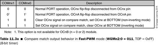
28 Using the CTC Mode.include <m2560def.inc>.def tmp = r16.cseg.org 0x00 rjmp start.org 0xF6 start: ldi r16,low(ramend) out SPL,r16 ldi r16,high(ramend) out SPH,r16 ldi r16,0x20 ; configure PD5/OC1A pin for output sts DDRB,r16 ; ldi tmp,1<<com1a0 ; configure Timer1 to CTC mode (WGM13:0: 1100) sts TCCR1A,tmp ; and make OC1A pin toggle clr tmp ; force timer1 to count up from 0 sts TCNT1L,tmp ; " sts TCNT1H,tmp ; " ldi tmp,high(4000) ; place 4000 as the TOP value sts ICR1H,tmp ; " ldi tmp,low(4000) ; sts ICR1L,tmp ; " ldi tmp,1<<wgm13 1<<WGM12 1<<CS10; sts TCCR1B,tmp ; to generate the 2 khz square wave with 50% duty cycle again: jmp again 55 Using the Fast PWM Mode Compare match pin action in fast PWM mode Figure Fast PWM mode waveforms 56 28
29 Using the Fast PWM Mode (cont d.) Using OCRnA to hold the TOP value Advantage: generated PWM waveform is always symmetric Using ICRn to hold the TOP value Works well when the TOP value is fixed Extreme cases for the fast PWM OCRnx register is set equal to the BOTTOM Setting the OCRnx equal to TOP 57 Using the Fast PWM Mode (cont d.) Example: Write a sequence of C statements to be run on a ATmega640/1280/2560 demo board to generate a 200-Hz frequency waveform with a 70% duty cycle in fast PWM mode from the OC1A pin and use ICR1 to hold the TOP value assuming that f clk_i/o = 16 MHz. Solution: DDRB = 1<<5; // configure PB5/OC1A pin for output TCNT1 = 0; // force timer1 to count up from 0 ICR1 = 10000; // set counter TOP value to 10,000 OCR1A = 7000; // set duty cycle to 70% TCCR1A = 1<<COM1A1 1<< WGM11 // select non inverting, fast PWM mode TCCR1B = 1<<WGM13 1<<WGM12 1<< CS11; // select clk_io/8 as clock source and ICR1A as TOP 58 29
30 Using the Fast PWM Mode (cont d.) example: write a sequence of AVR instructions and C statements to be executed by ATMega640 MCU to generate a 2KHz waveform with 80% duty cycle from the OC1B pin using timer 1, assuming fclk_i/o=16mhz selecting clk_i/o/64 as source, high and low of the 2KHz wave form consist of 100 and 25 timer clock cycles. 59 Using the Fast PWM Mode (cont d.) solution: We will use the fast-pwm non-inverting mode to generate this waveform. We will set the clock source to clk_i/o 64. The TOP value is calculated to be ( ) = 125. The value to set the duty cycle is % = 100. Assembly program to generate a 2-kHz waveform with 80% duty cycle that uses fast-pwm noninverting mode is as follows:.def tmp = r16 ldi tmp,0x20 ; configure OC0B/PG5 pin for output sts DDRG,tmp ; ldi tmp,1<<com0b1 1<<WGM01 1<<WGM00; non inverting fast PWM out TCCR0A,tmp ; use OCR0A as TOP value ldi tmp,125 ; set period to 0.5 ms out OCR0A,tmp ; ldi tmp,100 ; set duty cycle to 80% out OCR0B,tmp ; ldi tmp,1<<wgm02 1<<CS01 1<<CS00; select clk_i/o / 64 input out TCCR0B,tmp ; C program to generate a 2 khz waveform with 80% duty cycle is as follows: DDRG = 0x20; // configure OC0B/PG5 pin for output TCCR0A = 1<<COM0B1 1<<WGM01 1<<WGM00 // non inverting PWM OCR0A = 125; // set up signal period to 0.5 ms OCR0B = 100; // set up waveform duty cycle to 80% TCCR0B = 1<<WGM02 1<<CS01 1<<CS00; // clk_i/o / 64 as timer 0 clock input 60 30
31 Using the Phase-Correct PWM Mode 61 Using the Phase-Correct PWM Mode The choice of the TOP value 8-bit timer: 0 FF or the OCRnA register (n= 0 or 2) 16-bit timer: 0 00FF, 0 01FF, 0 03FF, the value in the OCRnA register, or the value in the ICRn register 62 31
32 Using the Phase-Correct PWM Mode (cont d.) Pin action on compare match in the phasecorrect PWM mode Refer to Tables 11.4 and 11.9 Only the pin action choice 2 (non-inverting mode) and 3 (inverting mode) should be selected 63 Using the Phase-Correct PWM Mode (cont d.) Example: Use the OC0A pin to generate a 40% duty cycle PWM waveform using the phase correct PWM non inverting mode. Assuming clk_i/o is 16MHZ and the prescaler is set to
33 Using the Phase-Correct PWM Mode (cont d.) ;TOP value is set to OXFF.include <m2560def.inc>.cseg.org 0x00 Rjmp start.org 0xF6 start: ldi r20,low(ramend) out SPL,r20 Ldi r20,high(ramend) out SPH,r20 DDRB =0x80; TCCR0A =1<<COM0A1 WGM00; TCCR0B =1<<CS01; OCR0A =102 TCNT0 =0;.def tmp = R16 ldi tmp,0x80; configure the PB7/OC0A pin for output out DDRB,tmp; " ldi tmp,1<<com0a1 1<<WGM00;OC0A to phase correct PWM;non inverting mode out TCCR0A,tmp; ldi tmp,1<<cs01; select clk_i/o / 8 as the clock out TCCR0B,tmp; to TCNT0 ldi tmp,102; set duty cycle to 40% out OCR0A,tmp; " ldi tmp,0; force TCNT0 to count up from 0 out TCNT0,tmp; " 65 Using the Phase and Frequency Correct PWM Mode Based on a dual-slope operation Available only in a 16-bit timer Counter counts repeatedly from BOTTOM to TOP and then from TOP to BOTTOM f PFCPWM = (f CLK_I/O timer prescaler) (2 TOP) The procedure of generating the PWM waveform using PFCPWM is identical to the PCPWM mode 66 33
34 Using the Phase and Frequency Correct PWM Mode Example: Write a sequence of AVR instructions to be run on a ATmega640/1280/2560 demo board to generate a 50-Hz PWM waveform with 5% duty cycle using the phase and frequency correct PWM from the OC1A pin and use ICR1 to hold the TOP value assuming that f clk_i/o = 16 MHz. Solution: We will select clk_io/8 as the clock source to Timer1 and the TOP value is calculated to be TOP = /(2 8 50) = 20,000 The value to set duty cycle to 5% is 20,000 * 5% = Using the Phase and Frequency Correct PWM Mode ldi r16,0x20 ; configure PB5/OC1A pin for output sts DDRB,r16 ; " ldi r16,0x2f ; clear all Timer1 flags sts TIFR1,r16 ; " clr r16 ; force Timer1 to count up from 0 sts TCNT1H,r16 ; " sts TCNT1L,r16 ; " ldi r16,high(20000) ; set up TOP value sts ICR1H,r16 ; " ldi r16,low(20000) ; " sts ICR1L,r16 ; " ldi r16,high(1000) ; set up duty cycle value to 5% sts OCR1AH,r16 ; " ldi r16,low(1000) ; " sts OCR1AL,r16 ; " ldi r16,1<<com1a1 ; select phase and frequency correct PWM mode and sts TCCR1A,r16 ; use ICR1 to hold TOP count ldi r16,1<<wgm13 1<<CS11 ; select clk_io/8 as clock input to Timer1 sts TCCR1B,r16 ; and enable Timer
35 Driving the DC Motor DC motor: analog motor Figure Simplified DC motor control circuit 69 Driving the DC Motor DC Motor Driver ICs Available in many current and voltage ratings Example: SN from TI Driving a DC Motor Using the SN Illustrated in Figure The output waveform of the Hall-effect transistor 70 35
36 Driving the DC Motor 71 Driving the DC Motor Normal Operation: OC1A output WPM, OC1B output 0v Reverse operation OC1A output 0V, OC1B output WPM Brake the motor OC1A 0V, OC1B 5V
L13: (25%), (20%), (5%) ECTE333
, (20%), (5%) ECTE333") ECTE333 s schedule ECTE333 Lecture 1 - Pulse Width Modulator School of Electrical, Computer and Telecommunications Engineering University of Wollongong Australia Week Lecture (2h) Tutorial (1h) Lab (2h)
ECTE333 s schedule ECTE333 Lecture 1 - Pulse Width Modulator School of Electrical, Computer and Telecommunications Engineering University of Wollongong Australia Week Lecture (2h) Tutorial (1h) Lab (2h)
Design with Microprocessors
 Design with Microprocessors Year III Computer Science 1-st Semester Lecture 5: AVR timers Timers AVR timers 8 bit timers/counters 16 bit timers/counters Characteristics Input clock prescaler Read / write
Atmel ATmega328P Timing Subsystems. Reading
 1 P a g e Atmel ATmega328P Timing Subsystems Reading The AVR Microcontroller and Embedded Systems using Assembly and C) by Muhammad Ali Mazidi, Sarmad Naimi, and Sepehr Naimi Chapter 9: Programming Timers
Timer/Counter with PWM
 Timer/Counter with PWM The AVR Microcontroller and Embedded Systems using Assembly and C) by Muhammad Ali Mazidi, Sarmad Naimi, and Sepehr Naimi ATMEL 8-bit AVR Microcontroller with 4/8/16/32K Bytes In-System
3DoT C++ Timer/Counter 4 with PWM
 3DoT C++ Timer/Counter 4 with PWM This article is on the motor control section of the 3DoT board using Timer/Counter 4 operating in Fast PWM mode. The AVR Microcontroller and Embedded Systems using Assembly
ATmega16A Microcontroller
 ATmega16A Microcontroller Timers 1 Timers Timer 0,1,2 8 bits or 16 bits Clock sources: Internal clock, Internal clock with prescaler, External clock (timer 2), Special input pin 2 Features The choice of
Counter/Timers in the Mega8
 Counter/Timers in the Mega8 The mega8 incorporates three counter/timer devices. These can: Be used to count the number of events that have occurred (either external or internal) Act as a clock Trigger
A MORON'S GUIDE TO TIMER/COUNTERS v2.2. by
 A MORON'S GUIDE TO TIMER/COUNTERS v2.2 by RetroDan@GMail.com TABLE OF CONTENTS: 1. THE PAUSE ROUTINE 2. WAIT-FOR-TIMER "NORMAL" MODE 3. WAIT-FOR-TIMER "NORMAL" MODE (Modified) 4. THE TIMER-COMPARE METHOD
Timer 0 Modes of Operation. Normal Mode Clear Timer on Compare Match (CTC) Fast PWM Mode Phase Corrected PWM Mode
 Fast PWM Mode Phase Corrected PWM Mode") Timer 0 Modes of Operation Normal Mode Clear Timer on Compare Match (CTC) Fast PWM Mode Phase Corrected PWM Mode PWM - Introduction Recall: PWM = Pulse Width Modulation We will mostly use it for controlling
Timer 0 Modes of Operation Normal Mode Clear Timer on Compare Match (CTC) Fast PWM Mode Phase Corrected PWM Mode PWM - Introduction Recall: PWM = Pulse Width Modulation We will mostly use it for controlling
Application Note: Using the Motor Driver on the 3pi Robot and Orangutan Robot Controllers
 Application Note: Using the Motor Driver on the 3pi Robot and Orangutan Robot 1. Introduction..................................................... 2 2. Motor Driver Truth Tables.............................................
Building Interactive Devices and Objects. Prof. Dr. Michael Rohs, Dipl.-Inform. Sven Kratz MHCI Lab, LMU München
 Building Interactive Devices and Objects Prof. Dr. Michael Rohs, Dipl.-Inform. Sven Kratz michael.rohs@ifi.lmu.de MHCI Lab, LMU München Today Servo Motors DC Motors Stepper Motors Motor Drivers PWM WLAN
The Interface Communicate to DC motor control. Iu Retuerta Cornet
 The Interface Communicate to DC motor control Iu Retuerta Cornet Mälardalens University, IDT department Supervisor and examiner : Lars Asplund 26 th May 2010 Abstract Mälardalens University makes internationally
MICROCONTROLLER TUTORIAL II TIMERS
 MICROCONTROLLER TUTORIAL II TIMERS WHAT IS A TIMER? We use timers every day - the simplest one can be found on your wrist A simple clock will time the seconds, minutes and hours elapsed in a given day
CSCI1600 Lab 4: Sound
 CSCI1600 Lab 4: Sound November 1, 2017 1 Objectives By the end of this lab, you will: Connect a speaker and play a tone Use the speaker to play a simple melody Materials: We will be providing the parts
AVR PWM 11 Aug In the table below you have symbols used in the text. The meaning of symbols is the same in the entire guide.
 Aquaticus PWM guide AVR PWM 11 Aug 29 Introduction This guide describes principles of PWM for Atmel AVR micro controllers. It is not complete documentation for PWM nor AVR timers but tries to lighten some
Embedded Hardware Design Lab4
 Embedded Hardware Design Lab4 Objective: Controlling the speed of dc motor using light sensor (LDR). In this lab, we would want to control the speed of a DC motor with the help of light sensor. This would
Chapter 6 PROGRAMMING THE TIMERS
 Chapter 6 PROGRAMMING THE TIMERS Force Outputs on Outcompare Input Captures Programmabl e Prescaling Prescaling Internal clock inputs Timer-counter Device Free Running Outcompares Lesson 2 Free Running
Grundlagen Microcontroller Counter/Timer. Günther Gridling Bettina Weiss
 Grundlagen Microcontroller Counter/Timer Günther Gridling Bettina Weiss 1 Counter/Timer Lecture Overview Counter Timer Prescaler Input Capture Output Compare PWM 2 important feature of microcontroller
Microcontroller: Timers, ADC
 Microcontroller: Timers, ADC Amarjeet Singh February 1, 2013 Logistics Please share the JTAG and USB cables for your assignment Lecture tomorrow by Nipun 2 Revision from last class When servicing an interrupt,
Department of Mechanical and Aerospace Engineering ME106 Fundamentals of Mechatronics Andrew Nguyen Ryan Nunn-Gage Amir Sepahmansour Maryam Sotoodeh
 NATCAR Department of Mechanical and Aerospace Engineering ME106 Fundamentals of Mechatronics Andrew Nguyen Ryan Nunn-Gage Amir Sepahmansour Maryam Sotoodeh May 16, 2006 Table of Contents I. Summary..3
Lecture 12 Timer Functions
 CPE 390: Microprocessor Systems Spring 2018 Lecture 12 Timer Functions Bryan Ackland Department of Electrical and Computer Engineering Stevens Institute of Technology Hoboken, NJ 07030 Adapted from HCS12/9S12
Human-Robot Interaction Class Koosy Human-Robot Interaction Class
 ATmega128 (8bit AVR Microprocessor) Human-Robot Interaction Class 2008. 4. 28 Koosy 1 Contents Micro Controller Unit Overview ATmega128 Features Necessary Tools General I/O External Interrupt 8bit/16bit
uc Crash Course Whats is covered in this lecture Joshua Childs Joshua Hartman A. A. Arroyo 9/7/10
 uc Crash Course Joshua Childs Joshua Hartman A. A. Arroyo Whats is covered in this lecture ESD Choosing A Processor GPIO USARTS o RS232 o SPI Timers o Prescalers o OCR o ICR o PWM ADC Interupts 1 ESD KILLS!
Using the Z8 Encore! XP Timer
 Application Note Using the Z8 Encore! XP Timer AN013104-1207 Abstract Zilog s Z8 Encore! XP microcontroller consists of four 16-bit reloadable timers that can be used for timing, event counting or for
CprE 288 Introduction to Embedded Systems (Output Compare and PWM) Instructors: Dr. Phillip Jones
 Instructors: Dr. Phillip Jones") CprE 288 Introduction to Embedded Systems (Output Compare and PWM) Instructors: Dr. Phillip Jones 1 Announcements HW8: Due Sunday 10/29 (midnight) Exam 2: In class Thursday 11/9 This object detection lab
CprE 288 Introduction to Embedded Systems (Output Compare and PWM) Instructors: Dr. Phillip Jones 1 Announcements HW8: Due Sunday 10/29 (midnight) Exam 2: In class Thursday 11/9 This object detection lab
Hardware and software resources on the AVR family for the microcontroller project
 Hardware and software resources on the AVR family for the microcontroller project 1 1. Code Vision The C Compiler you use: CodeVisionAVR (CVAVR) Where can you find it? a (limited) version is available
Microprocessors & Interfacing
 Lecture overview Microprocessors & Interfacing /Output output PMW Digital-to- (D/A) Conversion input -to-digital (A/D) Conversion Lecturer : Dr. Annie Guo S2, 2008 COMP9032 Week9 1 S2, 2008 COMP9032 Week9
Hardware Flags. and the RTI system. Microcomputer Architecture and Interfacing Colorado School of Mines Professor William Hoff
 Hardware Flags and the RTI system 1 Need for hardware flag Often a microcontroller needs to test whether some event has occurred, and then take an action For example A sensor outputs a pulse when a model
Arduino Freq-Mite for Norcal NC40A Mike WA8BXN Jan 2018
 Arduino Freq-Mite for Norcal NC40A Mike WA8BXN Jan 2018 Dave Benson's (K1SWL) Freq-Mite is a popular frequency counter used as a digital readout in CW of the operating frequency of QRP transceivers. No
Roland Kammerer. 13. October 2010
 Peripherals Roland Institute of Computer Engineering Vienna University of Technology 13. October 2010 Overview 1. Analog/Digital Converter (ADC) 2. Pulse Width Modulation (PWM) 3. Serial Peripheral Interface
Course Introduction. Content 20 pages 3 questions. Learning Time 30 minutes
 Purpose The intent of this course is to provide you with information about the main features of the S08 Timer/PWM (TPM) interface module and how to configure and use it in common applications. Objectives
The MC9S12 Pulse Width Modulation System. Pulse Width Modulation
 The MC9S12 Pulse Width Modulation System o Introduction to PWM o Review of the Output Compare Function o Using Output Compare to generate a PWM signal o Registers used to enable the Output Capture Function
EE 308 Spring 2013 The MC9S12 Pulse Width Modulation System
 The MC9S12 Pulse Width Modulation System o Introduction to PWM o Review of the Output Compare Function o Using Output Compare to generate a PWM signal o Registers used to enable the Output Capture Function
Hello, and welcome to this presentation of the FlexTimer or FTM module for Kinetis K series MCUs. In this session, you ll learn about the FTM, its
 Hello, and welcome to this presentation of the FlexTimer or FTM module for Kinetis K series MCUs. In this session, you ll learn about the FTM, its main features and the application benefits of leveraging
AVR 8-Bit Microcontroller
 ATmega8A Data Sheet Introduction The ATmega8A is a low-power CMOS 8-bit microcontroller based on the AVR enhanced RISC architecture. By executing powerful instructions in a single clock cycle, the ATmega8A
Analog Input and Output. Lecturer: Sri Parameswaran Notes by: Annie Guo
 Analog Input and Output Lecturer: Sri Parameswaran Notes by: Annie Guo 1 Analog output Lecture overview PMW Digital-to-Analog (D/A) Conversion Analog input Analog-to-Digital (A/D) Conversion 2 PWM Analog
Microcontroller Based Inductance Meter. David Nguyen
 Microcontroller Based Inductance Meter By David Nguyen Advisor: William Ahlgren Senior Project ELECTRICAL ENGINEERING DEPARTMENT California Polytechnic State University San Luis Obispo Spring 2011 Fall
Lecture #4 Outline. Announcements Project Proposal. AVR Processor Resources
 October 11, 2002 Stanford University - EE281 Lecture #4 #1 Announcements Project Proposal Lecture #4 Outline AVR Processor Resources A/D Converter (Analog to Digital) Analog Comparator Real-Time clock
EE152 Green Electronics
 EE152 Green Electronics Embedded Software 9/26/13 Prof. William Dally Computer Systems Laboratory Stanford University 1 Logistics Homework 1 due next Tuesday 10/1 Sign up for Lab signoff time Lab 1 must
PWM System. Microcomputer Architecture and Interfacing Colorado School of Mines Professor William Hoff
 PWM System 1 Pulse Width Modulation (PWM) Pulses are continuously generated which have different widths but the same period between leading edges Duty cycle (% high) controls the average analog voltage
A Beginners Guide to AVR
 See discussions, stats, and author profiles for this publication at: http://www.researchgate.net/publication/263084656 A Beginners Guide to AVR TECHNICAL REPORT JUNE 2014 DOWNLOADS 154 VIEWS 50 1 AUTHOR:
ATmega 16. Dariusz Chaberski
 ATmega 16 Dariusz Chaberski Obudowy 2 Schemat blokowy 3 4 5 Pamięć EEPROM The EEPROM Address Register The EEPROM Data Register 6 The EEPROM Control Register EERIE: EEPROM Ready Interrupt Enable EEMWE:
Crayfish Stretch Receptor Stimulator
 Crayfish Stretch Receptor Stimulator Report for Cornell University ECE MEng design project By Zequn Huang Ningning Ding Jiachen Hu Project Advisor: Bruce Land Bruce Johnson 1 ABSTRACT This project aims
 Chapter 5 Timer Functions ECE 3120 Dr. Mohamed Mahmoud http://iweb.tntech.edu/mmahmoud/ mmahmoud@tntech.edu Outline 5.1 The Timer System 5.2 Programming the Timer System 5.3 Examples and Applications The
ME 333 Assignment 7 and 8 PI Control of LED/Phototransistor Pair. Overview
 ME 333 Assignment 7 and 8 PI Control of LED/Phototransistor Pair Overview For this assignment, you will be controlling the light emitted from and received by an LED/phototransistor pair. There are many
Lab 5 Timer Module PWM ReadMeFirst
 Lab 5 Timer Module PWM ReadMeFirst Lab Folder Content 1) ReadMeFirst 2) Interrupt Vector Table 3) Pin out Summary 4) DriverLib API 5) SineTable Overview In this lab, we are going to use the output hardware
Small DC Motor Control
 APPLICATION NOTE Small DC Motor Control JAFAR MODARES ECO APPLICATIONS September 1988 Order Number 270622-001 Information in this document is provided in connection with Intel products Intel assumes no
8-bit Microcontroller. Application Note. AVR081: Replacing AT90S4433 by ATmega8. Features. Introduction. AT90S4433 Errata Corrected in ATmega8
 AVR081: Replacing AT90S4433 by ATmega8 Features AT90S4433 Errata Corrected in ATmega8 Differences in Pin-out Changes to Names Improvements to Timer/Counters and Prescalers Changes to ADC Changes to Power
APPENDIX 1 FEATURES OF MICROCONTROLLER 89C51
 120 APPENDIX 1 FEATURES OF MICROCONTROLLER 89C51 121 122 123 124 125 126 APPENDIX 2 ATMEGA8 MICROCONTROLLER CODE ;---------------------------------------------------------------------------------------------
Topics Introduction to Microprocessors
 Topics 2244 Introduction to Microprocessors Chapter 8253 Programmable Interval Timer/Counter Suree Pumrin,, Ph.D. Interfacing with 886/888 Programming Mode 2244 Introduction to Microprocessors 2 8253/54
Written by Hans Summers Wednesday, 15 November :53 - Last Updated Wednesday, 15 November :07
 This is a phantastron divider based on the HP522 frequency counter circuit diagram. The input is a 2100Hz 15V peak-peak signal from my 2.1kHz oscillator project. Please take a look at the crystal oscillator
EARTH PEOPLE TECHNOLOGY, Inc. FAST ARDUINO OSCILLOSCOPE PROJECT User Manual
 EARTH PEOPLE TECHNOLOGY, Inc FAST ARDUINO OSCILLOSCOPE PROJECT User Manual The Fast Oscilloscope is designed for EPT USB CPLD Development System. It converts an analog signal to digital and displays the
Candidate: Achema Hosea Egbubu (142773) Title: Monitoring 50/60Hz Grid Coupling A Study In Conjunction with Wind-Energy Feed to Main Grids
 Title: Monitoring 50/60Hz Grid Coupling A Study In Conjunction with Wind-Energy Feed to Main Grids") Master Thesis 2016 Candidate: Achema Hosea Egbubu (142773) Title: Monitoring 50/60Hz Grid Coupling A Study In Conjunction with Wind-Energy Feed to Main Grids 0 CONTENTS ii Telemark University College Faculty
Master Thesis 2016 Candidate: Achema Hosea Egbubu (142773) Title: Monitoring 50/60Hz Grid Coupling A Study In Conjunction with Wind-Energy Feed to Main Grids 0 CONTENTS ii Telemark University College Faculty
ESE 350 Microcontroller Laboratory Lab 5: Sensor-Actuator Lab
 ESE 350 Microcontroller Laboratory Lab 5: Sensor-Actuator Lab The purpose of this lab is to learn about sensors and use the ADC module to digitize the sensor signals. You will use the digitized signals
CHAPTER 5 HARDWARE IMPLEMENTATION AND PERFORMANCE ANALYSIS OF CUK CONVERTER-BASED MPPT SYSTEM
 94 CHAPTER 5 HARDWARE IMPLEMENTATION AND PERFORMANCE ANALYSIS OF CUK CONVERTER-BASED MPPT SYSTEM 5.1 INTRODUCTION In coming up with a direct control adaptive perturb and observer MPPT method with Cuk converter,
Using NeoPixels and Servos Together
 Using NeoPixels and Servos Together Created by Phillip Burgess Last updated on 2017-07-10 03:45:03 AM UTC Guide Contents Guide Contents The Issue The Root of the Problem Using an M0 Board? Introducing
Section 35. Output Compare with Dedicated Timer
 Section 35. Output Compare with Dedicated Timer HIGHLIGHTS This section of the manual comprises the following major topics: 35.1 Introduction... 35-2 35.2 Output Compare Registers... 35-3 35.3 Modes of
Design and Implementation of AT Mega 328 microcontroller based firing control for a tri-phase thyristor control rectifier
 Design and Implementation of AT Mega 328 microcontroller based firing control for a tri-phase thyristor control rectifier 1 Mr. Gangul M.R PG Student WIT, Solapur 2 Mr. G.P Jain Assistant Professor WIT,
Implementation of Multiquadrant D.C. Drive Using Microcontroller
 Implementation of Multiquadrant D.C. Drive Using Microcontroller Author Seema Telang M.Tech. (IV Sem.) Department of Electrical Engineering Shri Ramdeobaba College of Engineering and Management Abstract
Timing System. Timing & PWM System. Timing System components. Usage of Timing System
 Timing & PWM System Timing System Valvano s chapter 6 TIM Block User Guide, Chapter 15 PWM Block User Guide, Chapter 12 1 2 Timing System components Usage of Timing System 3 Counting mechanisms Input time
Hello and welcome to this Renesas Interactive Course that provides an overview of the timers found on RL78 MCUs.
 Hello and welcome to this Renesas Interactive Course that provides an overview of the timers found on RL78 MCUs. 1 The purpose of this course is to provide an introduction to the RL78 timer Architecture.
8-bit Microcontroller with 8K Bytes In-System Programmable Flash. ATmega8535 ATmega8535L
 Features High-performance, Low-power AVR 8-bit Microcontroller Advanced RISC Architecture 130 Powerful Instructions Most Single Clock Cycle Execution 32 x 8 General Purpose Working Registers Fully Static
PIC Functionality. General I/O Dedicated Interrupt Change State Interrupt Input Capture Output Compare PWM ADC RS232
 PIC Functionality General I/O Dedicated Interrupt Change State Interrupt Input Capture Output Compare PWM ADC RS232 General I/O Logic Output light LEDs Trigger solenoids Transfer data Logic Input Monitor
8-bit Microcontroller with 2/4/8K Bytes In-System Programmable Flash. ATtiny24/44/84. Preliminary
 Features High Performance, Low Power AVR 8-Bit Microcontroller Advanced RISC Architecture 120 Powerful Instructions Most Single Clock Cycle Execution 32 x 8 General Purpose Working Registers Fully Static
8-bit Microcontroller with 4K Bytes In-System Programmable Flash and Boost Converter. ATtiny43U. Preliminary
 Features High Performance, Low Power AVR 8-Bit Microcontroller Advanced RISC Architecture 120 Powerful Instructions Most Single Clock Cycle Execution 32 x 8 General Purpose Working Registers Fully Static
8-bit Microcontroller with 16K Bytes In-System Programmable Flash. ATtiny1634
 Features High Performance, Low Power AVR 8-bit Microcontroller Advanced RISC Architecture 125 Powerful Instructions Most Single Clock Cycle Execution 32 x 8 General Purpose Working Registers Fully Static
ATtiny102 / ATtiny104. Introduction. Feature. 8-bit AVR Microcontroller DATASHEET COMPLETE
 8-bit AVR Microcontroller ATtiny102 / ATtiny104 DATASHEET COMPLETE Introduction The Atmel ATtiny102/ATtiny104 is a low-power CMOS 8-bit microcontroller based on the AVR enhanced RISC architecture. By executing
COMP 4550 Servo Motors
 COMP 4550 Servo Motors Autonomous Agents Lab, University of Manitoba jacky@cs.umanitoba.ca http://www.cs.umanitoba.ca/~jacky http://aalab.cs.umanitoba.ca Servo Motors A servo motor consists of three components
Hello, and welcome to this presentation of the STM32L4 comparators. It covers the main features of the ultra-lowpower comparators and some
 Hello, and welcome to this presentation of the STM32L4 comparators. It covers the main features of the ultra-lowpower comparators and some application examples. 1 The two comparators inside STM32 microcontroller
8-bit Microcontroller with 2K/4K/8K Bytes In-System Programmable Flash. ATtiny24A ATtiny44A ATtiny84A
 Features High Performance, Low Power AVR 8-bit Microcontroller Advanced RISC Architecture 12 Powerful Instructions Most Single Clock Cycle Execution 32 x 8 General Purpose Working Registers Fully Static
EEL 4744C: Microprocessor Applications Lecture 8 Timer Dr. Tao Li
 EEL 4744C: Microprocessor Applications Lecture 8 Timer Reading Assignment Software and Hardware Engineering (new version): Chapter 14 SHE (old version): Chapter 10 HC12 Data Sheet: Chapters 12, 13, 11,
Reading Assignment. Timer. Introduction. Timer Overview. Programming HC12 Timer. An Overview of HC12 Timer. EEL 4744C: Microprocessor Applications
 Reading Assignment EEL 4744C: Microprocessor Applications Lecture 8 Timer Software and Hardware Engineering (new version): Chapter 4 SHE (old version): Chapter 0 HC Data Sheet: Chapters,,, 0 Introduction
Design of a Frequency Counter Based on Input Capture Function of a. Single Chip Computer. Wang Yanshuang; Liu Yuelong
 7th International Conference on Advanced Design and Manufacturing Engineering (ICADME 2017) Design of a Frequency Counter Based on Input Capture Function of a Single Chip Computer Wang Yanshuang; Liu Yuelong
FR FAMILY MB91460 PROGRAMMABLE PULSE GENERATOR 32-BIT MICROCONTROLLER APPLICATION NOTE. Fujitsu Microelectronics Europe Application Note
 Fujitsu Microelectronics Europe Application Note MCU-AN-300061-E-V11 FR FAMILY 32-BIT MICROCONTROLLER MB91460 PROGRAMMABLE PULSE GENERATOR APPLICATION NOTE Revision History Revision History Date Issue
8-bit with 8K Bytes In-System Programmable Flash. ATmega8 ATmega8L. Preliminary
 Features High-performance, Low-power AVR 8-bit Microcontroller Advanced RISC Architecture 130 Powerful Instructions Most Single-clock Cycle Execution 32 x 8 General Purpose Working Registers Fully Static
LM4: The timer unit of the MC9S12DP256B/C
 Objectives - To explore the Enhanced Capture Timer unit (ECT) of the MC9S12DP256B/C - To program a real-time clock signal with a fixed period and display it using the onboard LEDs (flashing light) - To
Real time digital audio processing with Arduino
 Real time digital audio processing with Arduino André J. Bianchi ajb@ime.usp.br Marcelo Queiroz mqz@ime.usp.br Departament of Computer Science Institute of Mathematics and Statistics University of São
AVR443: Sensorbased control of three phase Brushless DC motor. 8-bit Microcontrollers. Application Note. Features. 1 Introduction
 AVR443: Sensorbased control of three phase Brushless DC motor Features Less than 5us response time on Hall sensor output change Theoretical maximum of 1600k RPM Over-current sensing and stall detection
Measuring Distance Using Sound
 Measuring Distance Using Sound Distance can be measured in various ways: directly, using a ruler or measuring tape, or indirectly, using radio or sound waves. The indirect method measures another variable
Adding a Keyer to the Arduino Freq-Mite for the NC40A Mike WA8BXN Jan 2018
 Adding a Keyer to the Arduino Freq-Mite for the NC40A Mike WA8BXN Jan 2018 As mentioned in my previous project implementing a frequency readout in CW for the Norcal NC40A similar to the functionality of
Four Quadrant Speed Control of DC Motor with the Help of AT89S52 Microcontroller
 Four Quadrant Speed Control of DC Motor with the Help of AT89S52 Microcontroller Rahul Baranwal 1, Omama Aftab 2, Mrs. Deepti Ojha 3 1,2, B.Tech Final Year (Electronics and Communication Engineering),
8-bit Microcontroller with 16K Bytes In-System Programmable Flash. ATmega16 ATmega16L. Preliminary
 Features High-performance, Low-power AVR 8-bit Microcontroller Advanced RISC Architecture 131 Powerful Instructions Most Single-clock Cycle Execution 32 x 8 General Purpose Working Registers Fully Static
EE 308 Lab Spring 2009
 9S12 Subsystems: Pulse Width Modulation, A/D Converter, and Synchronous Serial Interface In this sequence of three labs you will learn to use three of the MC9S12's hardware subsystems. WEEK 1 Pulse Width
ELCT 912: Advanced Embedded Systems
 ELCT 912: Advanced Embedded Systems Lecture 5: PIC Peripherals on Chip Dr. Mohamed Abd El Ghany, Department of Electronics and Electrical Engineering The PIC Family: Peripherals Different PICs have different
8-bit Atmel tinyavr Microcontroller with 16K Bytes In-System Programmable Flash. ATtiny1634
 8-bit Atmel tinyavr Microcontroller with 16K Bytes In-System Programmable Flash Features High Performance, Low Power AVR 8-bit Microcontroller Advanced RISC Architecture 125 Powerful Instructions Most
8-bit Microcontroller with 1K Bytes Flash. ATtiny15. Advance Information. Features. Description. Pin Configurations
 Features High-performance, Low-power AVR 8-bit Microcontroller RISC Architecture 90 Powerful Instructions - Most Single Clock Cycle Execution 32 x 8 General Purpose Working Registers Fully Static Operation
For reference only Refer to the latest documents for details
 STM32F3 Technical Training For reference only Refer to the latest documents for details General Purpose Timers (TIM2/3/4/5 - TIM12/13/14 - TIM15/16/17 - TIM6/7/18) TIM2/5 TIM3/4/19 TIM12 TIM15 TIM13/14
8-bit Microcontroller with 32K Bytes In-System Programmable Flash. ATmega32 ATmega32L
 Features High-performance, Low-power AVR 8-bit Microcontroller Advanced RISC Architecture 131 Powerful Instructions Most Single-clock Cycle Execution 32 x 8 General Purpose Working Registers Fully Static
Embedded Systems and Software
 Embedded Systems and Software Notes on Lab 2 Embedded Systems in Vehicles Lecture 2-4, Slide 1 Lab 02 In this lab students implement an interval timer using a pushbutton switch, ATtiny45, an LED driver,
Generating DTMF Tones Using Z8 Encore! MCU
 Application Note Generating DTMF Tones Using Z8 Encore! MCU AN024802-0608 Abstract This Application Note describes how Zilog s Z8 Encore! MCU is used as a Dual-Tone Multi- (DTMF) signal encoder to generate
8-bit Microcontroller with 2/4/8K Bytes In-System Programmable Flash. Atmel ATtiny24/44/84. Automotive. Preliminary
 Features High Performance, Low Power AVR 8-bit Microcontroller Advanced RISC Architecture 120 Powerful Instructions Most Single Clock Cycle Execution 32 x 8 General Purpose Working Registers Fully Static
Microprocessor & Interfacing Lecture Programmable Interval Timer
 Microprocessor & Interfacing Lecture 30 8254 Programmable Interval Timer P A R U L B A N S A L A S S T P R O F E S S O R E C S D E P A R T M E N T D R O N A C H A R Y A C O L L E G E O F E N G I N E E
8-bit Microcontroller with 512/1024 Bytes In-System Programmable Flash. ATtiny4/5/9/10
 Features High Performance, Low Power AVR 8-Bit Microcontroller Advanced RISC Architecture 54 Powerful Instructions Most Single Clock Cycle Execution 16 x 8 General Purpose Working Registers Fully Static
AN2581 Application note
 AN2581 Application note STM32F10xxx TIM application examples Introduction This application note is intended to provide practical application examples of the STM32F10xxx TIMx peripheral use. This document,
Hi Hsiao-Lung Chan Dept Electrical Engineering Chang Gung University, Taiwan
 Timers and CCP Modules Hi Hsiao-Lung Chan Dept Electrical Engineering Chang Gung University, Taiwan chanhl@mail.cgu.edu.twcgu PIC18 Timers Timer2, Timer4 8-bit timers use instruction cycle clock as the
High performance, low power AVR 8-bit microcontroller Advanced RISC architecture. Non-volatile program and data memories. Peripheral features
 ATtiny24/44/84 8-bit AVR Microcontroller with 2/4/8K Bytes In-System Programmable Flash DATASHEET Features High performance, low power AVR 8-bit microcontroller Advanced RISC architecture 120 powerful
8-bit with 8K Bytes In-System Programmable Flash. ATmega8* ATmega8L*
 Features High-performance, Low-power AVR 8-bit Microcontroller Advanced RISC Architecture 130 Powerful Instructions Most Single-clock Cycle Execution 32 x 8 General Purpose Working Registers Fully Static
8-bit Microcontroller with 2/4/8K Bytes In-System Programmable Flash. ATtiny25/V * ATtiny45/V ATtiny85/V * * Preliminary
 Features High Performance, Low Power AVR 8-Bit Microcontroller Advanced RISC Architecture 120 Powerful Instructions Most Single Clock Cycle Execution 32 x 8 General Purpose Working Registers Fully Static
8-bit Microcontroller with 2/4/8K Bytes In-System Programmable Flash. ATtiny24/44/84. Preliminary
 Features High Performance, Low Power AVR 8-Bit Microcontroller Advanced RISC Architecture 120 Powerful Instructions Most Single Clock Cycle Execution 32 x 8 General Purpose Working Registers Fully Static