Arduino Freq-Mite for Norcal NC40A Mike WA8BXN Jan 2018
|
|
|
- Eunice Dean
- 6 years ago
- Views:
Transcription
1 Arduino Freq-Mite for Norcal NC40A Mike WA8BXN Jan 2018 Dave Benson's (K1SWL) Freq-Mite is a popular frequency counter used as a digital readout in CW of the operating frequency of QRP transceivers. No longer produced by Dave himself it is currently available from I present here similar functionality using an Arduino processor intended primarily for use with the Norcal NC40A QRP transceiver. Within its limitations noted below it could be used otherwise. Besides being a useful device it should serve as an example of how the functionality might be implemented using an Arduino. The hardware components are quite simple, shown in the schematic below: The switch is a push button that when pressed announces the frequency in CW on the audio output. The rest of the circuit on the left is a simple preamp that allows light coupling to the VFO. I used a 2N3904 transistor, many others (such as a 2N2222) should work as well. I used an Arduino Nano processor board, an Arduino UNO board will work as well but is of course larger. +5 volts is obtained from the Arduino board itself, which is powered by the supply to the NC40A which I indicate as +12 V. VFO input is obtained at the junction of R23 and C7 on the NC40A board and audio output is connected to the R7 and U3 pin 2 junction. For the capacitor shown above connected to D3 of the Arduino I used 100 pf. This value can be adjusted to give desired audio level. The 10 pf capacitor going to the VFO from the transistor could also be changed as needed. Keep it as small as possible to limit its effect on the VFO itself. It should be a NP0 so as to not introduce frequency drift in the VFO. If desired a piezo buzzer could be connected directly to D3 instead of feeding audio into the NC40A for the CW frequency announcement.

2 Many Arduino Nano boards don't provide much in the way of mounting the board itself. I used a scrap of circuit board and a U shaped piece of wire soldered to it for mounting. The ends of the wire were soldered to the two ground pins on the Nano board. Other components were soldered to the Nano board with the shell of the USB connector used as a ground point for the emitter of the transistor. Other construction methods could be used as well.

3 Above is the complete board. The output capacitor connected to D3 is not shown as it was connected to the NC40A board. Below are a couple other close ups of construction.
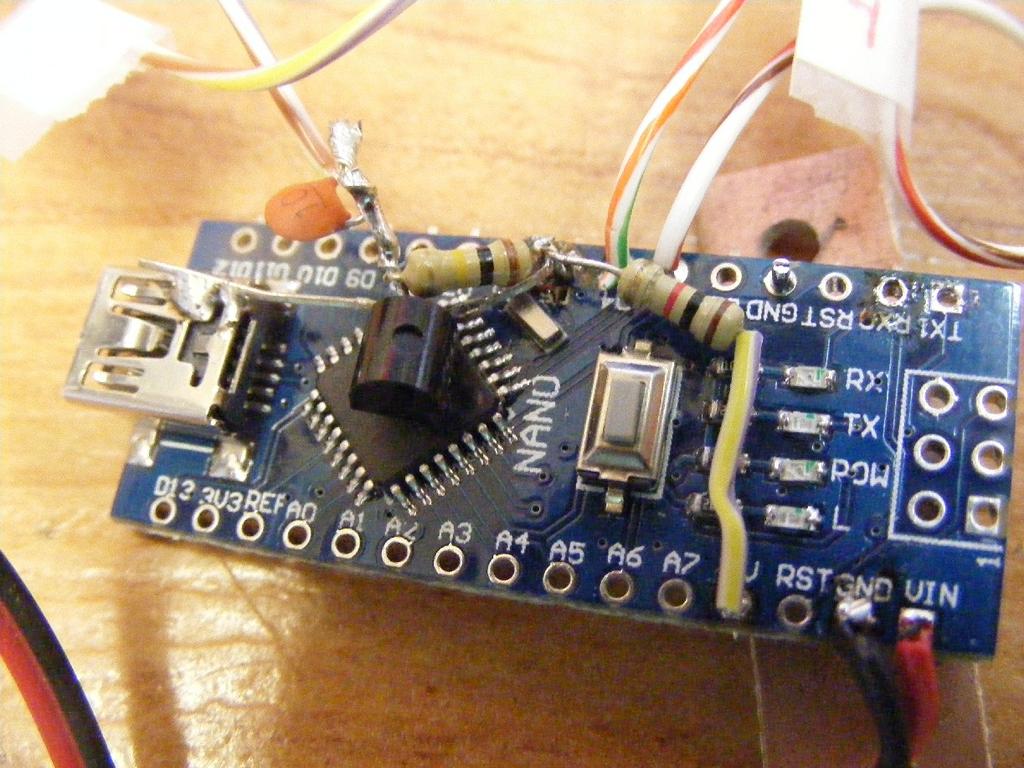
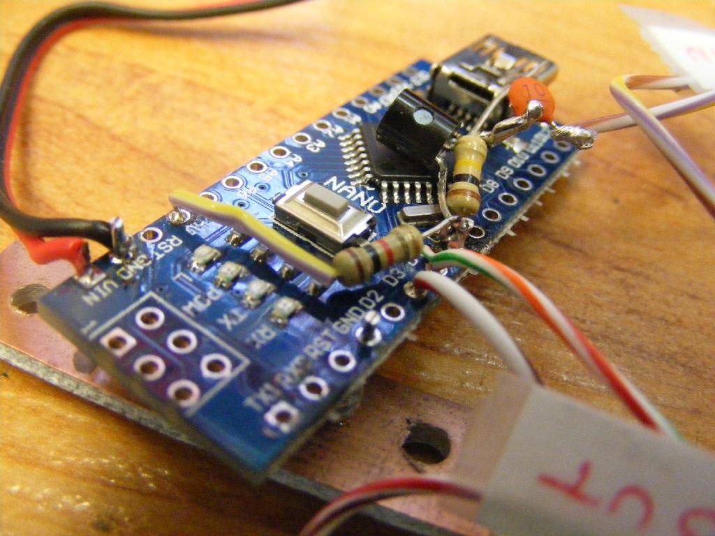
4
5 The original Freq-Mite had jumpers to select the IF offset frequency. Since the source code for the program is provided here that offset value is simply specified in one of the lines of code. Similarly adjustment of the CW speed is possible by changing a line of code instead of pressing the button at power up. Before looking at the program below some general background information is necessary for its understanding. Basically the program functions as a frequency counter that measures the frequency of the VFO in the NC40A, adds the IF offset frequency (around MHz) and then generates CW for the operating frequency. When the button is pressed this happens and the frequency in KHz is heard. To measure frequency one could watch the input signal in the program and count the number of cycles that occur in a given period of time. Testing the input to see when each cycle of input begins in code would greatly limit the frequency limit of what we could count. This would probably limit us to audio frequencies not the around 2 MHz at which the VFO operates. The trick used that allows us to count frequencies in the MHz range makes use of the fact that most of the processor chips are designed with a counter in the chip that can be used to count cycles in hardware without executing program instructions to recognize each cycle and do the counting. Access to this is not apparent in the normal description of programming in the Arduino environment but does exist and is documented somewhere. The hardware counter in the processor on the Arduino board is only 16 bits meaning it can only count up to a value of Beyond that value it just start over counting at zero again. Fortunately an interrupt is generated when the counter overflows and we can in our program count the number of times that occurs. From this we can compute larger counts. If you don't fully understand this detail its OK. Now our basic approach to frequency counting will be to use that hardware counter to count input cycles for us for some period of time. If we count for one second the resulting count would be the frequency in Hz. We don't need that much accuracy nor do we want to wait a whole second before hearing the frequency so the program only counts for 10 ms. The resulting value we will get will be in terms of hundreds of Hz. By default the program will only report the frequency in KHz. Un-commenting a few lines at the end of the program will allow it to report the frequency including tenths of KHz. Accuracy of the frequency we get from doing the cycle counting will depend on how accurately we can determine the period of time we do the counting. The Arduino processor board does have a crystal controlled timing oscillator running at 16 MHz. However there is no trimmer to adjust to get it exactly on frequency. As a result our timing should be fairly stable but not absolutely accurate. Provision is made in the program to compensate for that. Another issue is the value for the IF frequency to add to our frequency count. The crystals used in the filter are nominally MHz but where the center of the passband we get is a bit different. Another variable to this is the adjustment of trimmers C34 and C17. A constant in the program can be adjusted for these issues. The program below can be used as is most likely. Comments about modifications are included following the listing. Note that if you do use a Nano processor and have never done
6 so before you are likely going to need to install drivers found at If you use an Arduino UNO board needed drivers are included with installation of the Arduino programming environment (IDE). Installation of the Arduino IDE, programming in C and related topics are of course beyond the scope of this discussion but well covered elsewhere.
7 /* Arduino frequency counter for Norcal NC-40a with CW output Can be used with VFOs up to around 5 MHz Runs on Nano or UNO processor boards Mike WA8BXN Jan 2018 */ // Port definitions FREQ_IN 5 BUTTON 4 BUZZER 3 SPEED dittime IF_OFFSET CPU_FREQ_ADJ // Do NOT change this /SPEED volatile unsigned int overflowcounter; unsigned int frequency; char *code[10]= "-----", ".----","..---","...--","...-", "...","-...","--...","---..","----."; // Timer 1 is our counter // 16-bit counter overflows after counts // overflowcounter will keep track of how many times we overflow ISR(TIMER1_OVF_vect) // Interrupt handler overflowcounter++; void setup() // Timer 1 will be setup as a counter // Maximum frequency is Fclk_io/2 // (recommended to be < Fclk_io/2.5) // Fclk_io is 16MHz TCCR1A = 0; // External clock source on D5, trigger on rising edge: TCCR1B = (1<<CS12) (1<<CS11) (1<<CS10); // Enable overflow interrupt // Will jump into ISR(TIMER1_OVF_vect) when overflowed: TIMSK1 = (1<<TOIE1); pinmode(freq_in, INPUT); pinmode(button,input_pullup); pinmode(buzzer,output); Serial.begin(9600); Serial.println("Begin AFA"); OK(); void loop() if (digitalread(button)==low) freqcount(); // This is the frequency input // Console debug output // Startup msg in CW
8 void freqcount() // Delay 10 ms. While we're delaying Counter 1 is still // reading the input on D5, and also keeping track of how // many times it's overflowed char buf[20]; TCNT1=0; overflowcounter = 0; delaymicroseconds(cpu_freq_adj); frequency = TCNT * (unsigned long) overflowcounter; sprintf(buf,"vfo %5d.%d khz",frequency/10,frequency%10); Serial.println(buf); sendfreq(); // freq in 100s of Hz // Console debug output void dit() tone(buzzer,600); delay(dittime); notone(buzzer); delay(dittime); void dah() tone(buzzer,600); delay(3*dittime); notone(buzzer); delay(dittime); void OK() // send power up "OK" dah();dah();dah(); delay(3*dittime); dah();dit();dah(); delay(3*dittime); void senddigit(int n) char *p=code[n]; while (*p) if (*p++=='.') dit(); else dah(); delay(2*dittime); void sendfreq() long f; int n=0,tenths; int digits[10]; // // // // string for this digit for each character in string send dit or dah pause between digits // send frequency in CW to audio f=frequency+if_offset; Serial.print("Mixed freq "); Serial.println(f); // Debug output tenths=f%10; f=f/10; while (f) // get individual digits right to left digits[n++]=f%10;
9 f=f/10; n--; while (n>=0) // send digits left to right senddigit( digits[n--]); /* uncomment for tenths of KHz dit();dah();dit();delay(3*dittime); // send letter R for decimal place senddigit(tenths); */
10 For those that want to fine tune the program, there are 3 lines of code that are easy to change. They are found near the beginning of the listing: SPEED 15 IF_OFFSET CPU_FREQ_ADJ The value for speed is the simplest. Change 15 to the CW speed you prefer, in WPM. The other two require experimentation to determine the best values. The following procedure should be used. The value CPU_FREQ_ADJ allows us to compensate for variations in the 16 MHz CPU clock frequency. Connect a known frequency input to the circuit (1 MHz would be a good value). Start the Arduino IDE and connect the processor baord to the computer with a USB cable to get set up for programming the board. Load the source program into the IDE if its not already there. In the programming IDE, open the debugging monitor window. Press the button to read frequency. In the debug monitor window you will see something like this: Begin AFA VFO khz Mixed freq I just used the VFO rather than a 1 MHz input. With 1 MHz you want to get it to show VFO khz or what ever your known frequency input actually is. It must be less than around 5 MHz! Change the CPU_FREQ_ADJ value and recompile and upload the program and run again until you get as close as you can to the correct display. To adjust the number for IF_OFFSET connect the input to the VFO as would be used for normal operation. Tune the VFO to a know frequency using some independent standard. You could measure the transmit frequency of the NC40A or tune the receiver to hear a signal at a know frequency. Press the button and note the value displayed in the debug monitor window for Mixed freq. Change the number for IF_OFFSET to get it to display the right Mixed freq when the button is pushed. Concluding remarks I hope you find this project description useful. I think its fairly easy to actually build and get working, particularly if you have any Arduino experience already. You may have noticed that most of the time the program just sits waiting for that button to be pressed. I heard it begging for more to do and with a few more hardware parts and some more lines of code added a simple iambic keyer with a stored message as well but that is a story for next time!
Adding a Keyer to the Arduino Freq-Mite for the NC40A Mike WA8BXN Jan 2018
 Adding a Keyer to the Arduino Freq-Mite for the NC40A Mike WA8BXN Jan 2018 As mentioned in my previous project implementing a frequency readout in CW for the Norcal NC40A similar to the functionality of
Written by Hans Summers Wednesday, 15 November :53 - Last Updated Wednesday, 15 November :07
 This is a phantastron divider based on the HP522 frequency counter circuit diagram. The input is a 2100Hz 15V peak-peak signal from my 2.1kHz oscillator project. Please take a look at the crystal oscillator
Portland State University MICROCONTROLLERS
 PH-315 MICROCONTROLLERS INTERRUPTS and ACCURATE TIMING I Portland State University OBJECTIVE We aim at becoming familiar with the concept of interrupt, and, through a specific example, learn how to implement
 The Mountain Topper by Steve Weber (KD1JV) (MTR) www.lnrprecision.com FULLY ASSEMBLED Manufactured by LNR Precision, Inc. A very small, very efficient three band QRP CW rig. Specifications: Three bands,
CSCI1600 Lab 4: Sound
 CSCI1600 Lab 4: Sound November 1, 2017 1 Objectives By the end of this lab, you will: Connect a speaker and play a tone Use the speaker to play a simple melody Materials: We will be providing the parts
BITX40 with Raduino - tips and mods
 BITX40 with Raduino - tips and mods Also check out hfsigs blogspot http://bitxhacks.blogspot.co.uk/ Clicks during tuning I assume you are talking about the Raduino clicking as you tune. I'm not having
The. A PIC-Based Morse Frequency Counter. Specifications:
 The A PIC-Based Morse Frequency Counter Thanks for purchasing the Small Wonder Labs Freq-Mite, a Morse-readout frequency-annunciating device. The Freq-Mite is user programmable, so it's readily adaptable
W0EB/W2CTX Alternate Firmware for the Micro BITX meter Transceiver
 W0EB/W2CTX Alternate Firmware for the Micro BITX 80-10 meter Transceiver ubitx built by W0EB Instruction manual for the alternate ubitx transceiver software written by Ron Pfeiffer, W2CTX and Jim Sheldon,
ALX-SSB 5 Band Filter Assembly Manual 19 November 2018
 ALX-SSB 5 Band Filter Assembly Manual 19 November 2018 Contents Theory of Operation:... 1 Figure 1... 2 Parts Included:... 4 Board Overview:... 5 Figure 2... 5 Figure 3... 5 Board Assembly:... 6 Cable
TAPR TICC Timestamping Counter Operation Manual. Introduction
 TAPR TICC Timestamping Counter Operation Manual Revised: 23 November 2016 2016 Tucson Amateur Packet Radio Corporation Introduction The TAPR TICC is a two-channel timestamping counter ("TSC") implemented
Assembly Manual for VFO Board 2 August 2018
 Assembly Manual for VFO Board 2 August 2018 Parts list (Preliminary) Arduino 1 Arduino Pre-programmed 1 Faceplate Assorted Header Pins Full Board Rev A 10 104 capacitors 1 Rotary encode with switch 1 5-volt
LNR Precision Mountain Topper MTR-4B and MTR-5B REV 2.0 User Manual for use with versions with 16 x 2 display.
 LNR Precision Mountain Topper MTR-4B and MTR-5B REV 2.0 User Manual for use with versions with 16 x 2 display. Four band MTR 4B shown Overview: The Mountain Topper Rigs are designed to be a very small,
S-Pixie QRP Kit. Student Manual. Revision V 1-0
 S-Pixie QRP Kit Student Manual Revision V 1-0 Introduction The Pixie 2 is a small, versatile radio transceiver that is very popular with QRP (low power) amateur radio operators the world over. It reflects
QRPGuys SMT Digital Dial/Frequency Counter
 QRPGuys SMT Digital Dial/Frequency Counter First, familiarize yourself with the parts and check for all the components. If a part is missing, please contact us and we will send one. You must use qrpguys.parts@gmail.com
N3ZI Kits General Coverage Receiver, Assembly & Operations Manual (For Jun 2011 PCB ) Version 3.33, Jan 2012
 Version 3.33, Jan 2012") N3ZI Kits General Coverage Receiver, Assembly & Operations Manual (For Jun 2011 PCB ) Version 3.33, Jan 2012 Thank you for purchasing my general coverage receiver kit. You can use the photo above as a
N3ZI Kits General Coverage Receiver, Assembly & Operations Manual (For Jun 2011 PCB ) Version 3.33, Jan 2012 Thank you for purchasing my general coverage receiver kit. You can use the photo above as a
Dual Band Filter Assembly Manual
 Dual Band Filter Assembly Manual 12 January 2018 Rev D Version Theory of Operation: The purpose of a Bandpass Filter is to filter out or reject all unwanted signals. The original KN-Q7A Receive Filter
ICS REPEATER CONTROLLERS
 ICS REPEATER CONTROLLERS BASIC CONTROLLER USER MANUAL INTEGRATED CONTROL SYSTEMS 1076 North Juniper St. Coquille, OR 97423 Email support@ics-ctrl.com Website www.ics-ctrl.com Last updated 5/07/15 Basic
MTR-3B - LCD edition
 MTR-3B - LCD edition Mountain Topper User Manual Overview: The Mountain Topper Rigs are designed to be a very small, light weight, very battery efficient, multi-band CW rig suitable for field operation.
Beta-test ED1 PCB installed in I0CG s K1
 K1 SSB Modification (Ed.2) This description provides the receiver (RX) modifications, assembly, alignment and operation as a first step. In a second step you can add the remaining transmitter (TX) modifications,
: Hacking Bitx Version3B, C: : 20mt to 40mt band: PART I
 : Hacking Bitx Version3B, C: : 20mt to 40mt band: PART I Fig 1: Bitx Ver3C SBL-1 20 Conversion for Bitx40 The picture in Fig1 is a Bitx3C SBL-1 for 40mt band, constructed from the Bitx Version 3C SBL-1
BAND DECODER and CONTROLLE R. Accessibility Upgrade and Operating Instructions
 ELE CRAFT KRC2 BAND DECODER and CONTROLLE R Accessibility Upgrade and Operating Instructions Revision A, March 4, 2004. Copyright 2004, Elecraft; All Rights Reserved Introduction The KRC2 Accessibility
Chapter 15: Serial Controlled (HF) Radio Support
 Radio Support") 15-1 Chapter 15: Serial Controlled (HF) Radio Support This section describes the controller's interface for serial controlled radios. Most such radios are for the HF bands, but some such as the FT-736
15-1 Chapter 15: Serial Controlled (HF) Radio Support This section describes the controller's interface for serial controlled radios. Most such radios are for the HF bands, but some such as the FT-736
"Nighthawk" CW Transceiver Kit V3.1
 "Nighthawk" CW Transceiver Kit V3.1 Brief Introduction The "Nighthawk" CW transceiver is based on a well-known US design by Dave Benson, K1SWL at Small Wonder Labs. Its classic design includes a standard
RC Filters and Basic Timer Functionality
 RC-1 Learning Objectives: RC Filters and Basic Timer Functionality The student who successfully completes this lab will be able to: Build circuits using passive components (resistors and capacitors) from
Arduino Lesson 1. Blink. Created by Simon Monk
 Arduino Lesson 1. Blink Created by Simon Monk Guide Contents Guide Contents Overview Parts Part Qty The 'L' LED Loading the 'Blink' Example Saving a Copy of 'Blink' Uploading Blink to the Board How 'Blink'
Connecting the FCC-2 to the Hendricks DC Kits Bob Okas, W3CD
 Connecting the FCC-2 to the Hendricks DC Kits Bob Okas, W3CD This is an application note that describes how you can connect the NorCal FCC-1/2 combination to the DC kits. It involves a few extra components
HAW-Arduino. Sensors and Arduino F. Schubert HAW - Arduino 1
 HAW-Arduino Sensors and Arduino 14.10.2010 F. Schubert HAW - Arduino 1 Content of the USB-Stick PDF-File of this script Arduino-software Source-codes Helpful links 14.10.2010 HAW - Arduino 2 Report for
Part (A) Using the Potentiometer and the ADC* Part (B) LEDs and Stepper Motors with Interrupts* Part (D) Breadboard PIC Running a Stepper Motor
 Using the Potentiometer and the ADC* Part (B) LEDs and Stepper Motors with Interrupts* Part (D) Breadboard PIC Running a Stepper Motor") Name Name (Most parts are team so maintain only 1 sheet per team) ME430 Mechatronic Systems: Lab 5: ADC, Interrupts, Steppers, and Servos The lab team has demonstrated the following tasks: Part (A) Using
Name Name (Most parts are team so maintain only 1 sheet per team) ME430 Mechatronic Systems: Lab 5: ADC, Interrupts, Steppers, and Servos The lab team has demonstrated the following tasks: Part (A) Using
Sweep / Function Generator User Guide
 I. Overview Sweep / Function Generator User Guide The Sweep/Function Generator as developed by L. J. Haskell was designed and built as a multi-functional test device to help radio hobbyists align antique
Lazy Clock Electronics and Software
 Lazy Clock Electronics and Software Introduction The Lazy Clock is a wood gear mechanical clock driven by a low-power solenoid that fires only once per minute. An MSP430 microcontroller, clocked with a
Initial Power-Up Tests
 Initial Power-Up Tests The signal generator will not function properly until the blank EEPROM has been programmed with a set of default values. The CPU will accomplish this task if the RxTx control line
AN3252 Application note
 Application note Building a wave generator using STM8L-DISCOVERY Application overview This application note provides a short description of how to use the STM8L-DISCOVERY as a basic wave generator for
Written by Hans Summers Monday, 22 September :14 - Last Updated Friday, 16 January :43
 This modification turns the Ultimate3 kit into an accurate GPS-disciplined frequency reference (approx 0.03Hz accuracy). The firmware has NOT yet been updated to operate with the Si5351A synthesiser module
Arduino Microcontroller Processing for Everyone!: Third Edition / Steven F. Barrett
 Arduino Microcontroller Processing for Everyone!: Third Edition / Steven F. Barrett Anatomy of a Program Programs written for a microcontroller have a fairly repeatable format. Slight variations exist
JUMA-TRX2 DDS / Control Board description OH2NLT
 JUMA-TRX2 DDS / Control Board description OH2NLT 22.08.2007 General Key functions of the JUMA-TRX2 DDS / Control board are: - provide user interface functions with LCD display, buttons, potentiometers
MICROCONTROLLER TUTORIAL II TIMERS
 MICROCONTROLLER TUTORIAL II TIMERS WHAT IS A TIMER? We use timers every day - the simplest one can be found on your wrist A simple clock will time the seconds, minutes and hours elapsed in a given day
Youkits SK-1A 40m SSB/CW QRP Transceiver. Operating manual
 Youkits SK-1A 40m SSB/CW QRP Transceiver Operating manual Specifications Size: 88*38*124mm (not including knob, etc.) Weight: about 280g (not including battery pack) Supply voltage: 10-15VDC Current drain
ILER MK2. QRP SSB Transceiver in Kit Form Appendices. Last update: May 01, ILER-17 MK2 SSB QRP Transceiver Kit Page 1
 ILER MK2 QRP SSB Transceiver in Kit Form Appendices Last update: May 01, 2018 ea3gcy@gmail.com Most recent updates and news at: www.qsl.net/ea3gcy ILER-17 MK2 SSB QRP Transceiver Kit Page 1 APPENDIX 1:
ID Timer / Annunciator
 NØXAS ID Timer / Annunciator ID-O-Matic The ID-O-Matic is a single chip ID timer/annunciator intended for Amateur Radio and other applications. Several modes of operation make it suitable for use in the
ILER MK2. Appendices
 ILER MK2 QRP SSB Transceiver in Kit Form Appendices Last update: July 20, 2015 ea3gcy@gmail.com Most recent updates and news at: www.qsl.net/ea3gcy ILER-17 MK2 SSB QRP Transceiver Kit Page 1 APPENDIX 1:
A MORON'S GUIDE TO TIMER/COUNTERS v2.2. by
 A MORON'S GUIDE TO TIMER/COUNTERS v2.2 by RetroDan@GMail.com TABLE OF CONTENTS: 1. THE PAUSE ROUTINE 2. WAIT-FOR-TIMER "NORMAL" MODE 3. WAIT-FOR-TIMER "NORMAL" MODE (Modified) 4. THE TIMER-COMPARE METHOD
Counter/Timers in the Mega8
 Counter/Timers in the Mega8 The mega8 incorporates three counter/timer devices. These can: Be used to count the number of events that have occurred (either external or internal) Act as a clock Trigger
DDS VFO 2 CONSTRUCTION MANUAL. DDS VFO 2 Construction Manual Issue 1 Page 1
 DDS VFO 2 CONSTRUCTION MANUAL DDS VFO 2 Construction Manual Issue 1 Page 1 Important Please read before starting assembly STATIC PRECAUTION The DDS VFO kit contains the following components which can be
APDS-9960 RGB and Gesture Sensor Hookup Guide
 Page 1 of 12 APDS-9960 RGB and Gesture Sensor Hookup Guide Introduction Touchless gestures are the new frontier in the world of human-machine interfaces. By swiping your hand over a sensor, you can control
INA169 Breakout Board Hookup Guide
 Page 1 of 10 INA169 Breakout Board Hookup Guide CONTRIBUTORS: SHAWNHYMEL Introduction Have a project where you want to measure the current draw? Need to carefully monitor low current through an LED? The
ECED3204: Microprocessor Part IV--Timer Function
 ECED3204: Microprocessor Part IV--Timer Function Jason J. Gu Department of 1 Outline i. Introduction to the Microcontroller Timer System ii. Overview of the Mega AVR Timer System iii. Timer Clock Source
WSPR Audio Signal Source v2.0
 WSPR Audio Signal Source v2.0 A stand-alone WSPR signal source that generates audio WSPR tones to drive a SSB transmitter or transceiver. Features: - Internal timing or NMEA GPS timing for UTC synchronization
ATmega16A Microcontroller
 ATmega16A Microcontroller Timers 1 Timers Timer 0,1,2 8 bits or 16 bits Clock sources: Internal clock, Internal clock with prescaler, External clock (timer 2), Special input pin 2 Features The choice of
WSPR Audio Signal Source
 WSPR Audio Signal Source A stand-alone WSPR signal source that generates audio WSPR tones to drive a SSB transmitter or transceiver. Features: - Internal timing or NMEA GPS timing for UTC synchronization
Electronic Components
 Electronic Components Arduino Uno Arduino Uno is a microcontroller (a simple computer), it has no way to interact. Building circuits and interface is necessary. Battery Snap Battery Snap is used to connect
Follow this and additional works at: Part of the Engineering Commons
 Trinity University Digital Commons @ Trinity Mechatronics Final Projects Engineering Science Department 5-2016 Heart Beat Monitor Ivan Mireles Trinity University, imireles@trinity.edu Sneha Pottian Trinity
INTRODUCTION OPERATING INSTRUCTIONS
 INTRODUCTION Welcome to the world of effortless CW, with the MFJ-403 you ll have a professional sounding fist in no time! Whether you re a Novice or seasoned Extra, the MFJ-403 has the features you ve
Building a Bitx20 Version 3
 Building a Bitx20 Version 3 The board can be broken into sections and then built and tested one section at a time. This will make troubleshooting easier as any problems will be confined to one small section.
G1MFG.com. Home of the cheapest ATV transmitters and receivers in Europe! Please read all of this document before attempting to use your controller.
 G1MFG.com Home of the cheapest ATV transmitters and receivers in Europe! 23/24cm LCD controller technical information V3 software Please read all of this document before attempting to use your controller.
SCHOOL OF TECHNOLOGY AND PUBLIC MANAGEMENT ENGINEERING TECHNOLOGY DEPARTMENT
 SCHOOL OF TECHNOLOGY AND PUBLIC MANAGEMENT ENGINEERING TECHNOLOGY DEPARTMENT Course ENGT 3260 Microcontrollers Summer III 2015 Instructor: Dr. Maged Mikhail Project Report Submitted By: Nicole Kirch 7/10/2015
MFJ ENTERPRISES, INC.
 TM Model MFJ-402 INSTRUCTION MANUAL CAUTION: Read All Instructions Before Operating Equipment! MFJ ENTERPRISES, INC. 300 Industrial Park Road Starkville, MS 39759 USA Tel: 662-323-5869 Fax: 662-323-6551
ELECRAFT KX3 EXTENDED VFO TEMPERATURE COMPENSATION PROCEDURE Copyright 2012 Elecraft LLC Rev. A9, November 14, 2012
 ELECRAFT KX3 EXTENDED VFO TEMPERATURE COMPENSATION PROCEDURE Copyright 2012 Elecraft LLC Rev. A9, November 14, 2012 Introduction The KX3 standard VFO temperature compensation is entirely adequate for most
Lesson 3: Arduino. Goals
 Introduction: This project introduces you to the wonderful world of Arduino and how to program physical devices. In this lesson you will learn how to write code and make an LED flash. Goals 1 - Get to
EE445L Fall 2012 Final Version B Page 1 of 7
 EE445L Fall 2012 Final Version B Page 1 of 7 Jonathan W. Valvano First: Last: This is the closed book section. You must put your answers in the boxes on this answer page. When you are done, you turn in
J. La Favre Using Arduino with Raspberry Pi February 7, 2018
 As you have already discovered, the Raspberry Pi is a very capable digital device. Nevertheless, it does have some weaknesses. For example, it does not produce a clean pulse width modulation output (unless
UNIVERSAL-DDS-VFO UDV ( 1 Hz to 10 MHz)
") UNIVERSAL-DDS-VFO UDV ( 1 Hz to 10 MHz) Connection and operating instructions 1. Introduction The UDV is the ideal device to adapt older, VFO-controlled transceivers to modern requirements regarding frequency
UNIVERSAL-DDS-VFO UDV ( 1 Hz to 10 MHz) Connection and operating instructions 1. Introduction The UDV is the ideal device to adapt older, VFO-controlled transceivers to modern requirements regarding frequency
Pacific Antenna Simple Keyer Kit
 Pacific Antenna Simple Keyer Kit Specifications and Features: Speed range of 5 to 30 wpm Operates in either iambic A or B mode, with B being the default 2 message memories Tune and Beacon modes Built on
University of Utah Electrical Engineering Department ECE 2100 Experiment No. 2 Linear Operational Amplifier Circuits II
 University of Utah Electrical Engineering Department ECE 2100 Experiment No. 2 Linear Operational Amplifier Circuits II Minimum required points = 51 Grade base, 100% = 85 points Recommend parts should
The ROSE 80 CW Transceiver (Part 1 of 3)
") Build a 5 watt, 80 meter QRP CW Transceiver!!! Page 1 of 10 The ROSE 80 CW Transceiver (Part 1 of 3) Build a 5 watt, 80 meter QRP CW Transceiver!!! (Designed by N1HFX) A great deal of interest has been
Build a 5 watt, 80 meter QRP CW Transceiver!!! Page 1 of 10 The ROSE 80 CW Transceiver (Part 1 of 3) Build a 5 watt, 80 meter QRP CW Transceiver!!! (Designed by N1HFX) A great deal of interest has been
Magnetic Loop Antenna - Top Bands
 Magnetic Loop Antenna - Top Bands Instruction Manual Thank you for purchasing this new product small Magnetic Loop Antenna Top Bands. Manual contains important information. Please read all instructions
MicroFox2 Manual. Version 0.5 August 28, 2017
 Overview The Byonics MicroFox2 (MF2) is a small, 500mW, frequency agile 2-meter transceiver designed for hidden transmitter hunts, also called T-hunts, foxhunts, and ARDF. It is based on the Byonics MicroFox-PicCon,
Arduino STEAM Academy Arduino STEM Academy Art without Engineering is dreaming. Engineering without Art is calculating. - Steven K.
 Arduino STEAM Academy Arduino STEM Academy Art without Engineering is dreaming. Engineering without Art is calculating. - Steven K. Roberts Page 1 See Appendix A, for Licensing Attribution information
EGG 101L INTRODUCTION TO ENGINEERING EXPERIENCE
 EGG 101L INTRODUCTION TO ENGINEERING EXPERIENCE LABORATORY 7: IR SENSORS AND DISTANCE DEPARTMENT OF ELECTRICAL AND COMPUTER ENGINEERING UNIVERSITY OF NEVADA, LAS VEGAS GOAL: This section will introduce
Elmer Session Hand Out for 3/3/11 de W6WTI. Some Common Controls Found On Amateur Radio Transceivers. (From ARRL web site tutorial)
") Elmer Session Hand Out for 3/3/11 de W6WTI Some Common Controls Found On Amateur Radio Transceivers. (From ARRL web site tutorial) The placement of the controls may vary from manufacturer to manufacturer
Elmer Session Hand Out for 3/3/11 de W6WTI Some Common Controls Found On Amateur Radio Transceivers. (From ARRL web site tutorial) The placement of the controls may vary from manufacturer to manufacturer
Welcome to Arduino Day 2016
 Welcome to Arduino Day 2016 An Intro to Arduino From Zero to Hero in an Hour! Paul Court (aka @Courty) Welcome to the SLMS Arduino Day 2016 Arduino / Genuino?! What?? Part 1 Intro Quick Look at the Uno
Analog RF Electronics Education at SDSMT: A Hands-On Method for Teaching Electrical Engineers
 Analog RF Electronics Education at : A Hands-On Method for Teaching Electrical Engineers Dr., Professor Department of Electrical and Computer Engineering South Dakota School of Mines and Technology (whites@sdsmt.edu)
BeeLine TX User s Guide V1.1c 4/25/2005
 BeeLine TX User s Guide V1.1c 4/25/2005 1 Important Battery Information The BeeLine Transmitter is designed to operate off of a single cell lithium polymer battery. Other battery sources may be used, but
Hardware and software resources on the AVR family for the microcontroller project
 Hardware and software resources on the AVR family for the microcontroller project 1 1. Code Vision The C Compiler you use: CodeVisionAVR (CVAVR) Where can you find it? a (limited) version is available
Small RF Budget SRB MX145
 Small RF Budget SRB MX145 V 1.0.0 Thank you for choosing the SRB Module Transmitter as an addition to your ham radio equipment! We hope it will turn into an important tool for you in the years to come.
K1EL Granite State Crystal Matcher GS XTAL
 KEL Granite State Crystal Matcher GS XTAL FEATURES Two Display Configurations, LED or LCD Frequency Range up to 0 MHz +/- Hz accuracy Single Pushbutton Control Beeper output LED Mode: LED Readout Resolution
Build this Direct Digital Synthesizer "Development Kit" By: Diz Gentzow, W8DIZ
 Build this Direct Digital Synthesizer "Development Kit" By: Diz Gentzow, W8DIZ A great tutorial for adding a keypad to the DDS Kit by Bruce, W8BH This manual has been prepared to be read directly on screen.
WSPR VCXO Controller
 WSPR VCXO Controller A WSPR controller using pulse width modulation (PWM) to derive narrow-band 4-FSK modulation from a voltage controlled crystal oscillator (VCXO). Features: - Internal timing or NMEA
Module: Arduino as Signal Generator
 Name/NetID: Teammate/NetID: Module: Laboratory Outline In our continuing quest to access the development and debugging capabilities of the equipment on your bench at home Arduino/RedBoard as signal generator.
HF SIGNALS ΜBITX. The QRP HF General Coverage Transceiver you can build. Buy Now Circuit Description Wireup Tune Up Help and Support BITX Hacks
 Page 1 of 5 HF SIGNALS ΜBITX The QRP HF General Coverage Transceiver you can build Buy Now Circuit Description Wireup Tune Up Help and Support BITX Hacks ($109 USD) Page 2 of 5 The µbitx is a general coverage
Timer 0 Modes of Operation. Normal Mode Clear Timer on Compare Match (CTC) Fast PWM Mode Phase Corrected PWM Mode
 Fast PWM Mode Phase Corrected PWM Mode") Timer 0 Modes of Operation Normal Mode Clear Timer on Compare Match (CTC) Fast PWM Mode Phase Corrected PWM Mode PWM - Introduction Recall: PWM = Pulse Width Modulation We will mostly use it for controlling
Timer 0 Modes of Operation Normal Mode Clear Timer on Compare Match (CTC) Fast PWM Mode Phase Corrected PWM Mode PWM - Introduction Recall: PWM = Pulse Width Modulation We will mostly use it for controlling
MAE106 Laboratory Exercises Lab # 1 - Laboratory tools
 MAE106 Laboratory Exercises Lab # 1 - Laboratory tools University of California, Irvine Department of Mechanical and Aerospace Engineering Goals To learn how to use the oscilloscope, function generator,
Improving the Performance of the KSB2
 Introduction Improving the Performance of the KSB2 John Grebenkemper, KI6WX KI6WX@pacbell.net July 18, 2002 The following is a set of changes that I have done to my KSB2 and related circuits to improve
IZ602 LCD DRIVER Main features: Table 1 Pad description Pad No Pad Name Function
 LCD DRIVER The IZ602 is universal LCD controller designed to drive LCD with image element up to 128 (32x4). Instruction set makes IZ602 universal and suitable for applications with different types of displays.
UNIVERSITY OF VICTORIA FACULTY OF ENGINEERING. SENG 466 Software for Embedded and Mechatronic Systems. Project 1 Report. May 25, 2006.
 UNIVERSITY OF VICTORIA FACULTY OF ENGINEERING SENG 466 Software for Embedded and Mechatronic Systems Project 1 Report May 25, 2006 Group 3 Carl Spani Abe Friesen Lianne Cheng 03-24523 01-27747 01-28963
34112-TE 8-digit LED Frequency Counter Module Model PLJ-8LED-C User Manual V 1.0 May 2014
 34112-TE 8-digit LED Frequency Counter Module Model PLJ-8LED-C User Manual V 1.0 May 2014 Appendix with test details and schematics and additional notes in the main text of this manual were added in August
EE-110 Introduction to Engineering & Laboratory Experience Saeid Rahimi, Ph.D. Labs Introduction to Arduino
 EE-110 Introduction to Engineering & Laboratory Experience Saeid Rahimi, Ph.D. Labs 10-11 Introduction to Arduino In this lab we will introduce the idea of using a microcontroller as a tool for controlling
DIY KIT 141. Multi-Mode Timer
 INTRODUCTION No one can call themselves an electronics hobbyist unless they have built a timer. There are many tens of designs using a variety of new and sometimes old circuits. Witness the longest surviving
Exercise 3: Sound volume robot
 ETH Course 40-048-00L: Electronics for Physicists II (Digital) 1: Setup uc tools, introduction : Solder SMD Arduino Nano board 3: Build application around ATmega38P 4: Design your own PCB schematic 5:
Building and Operating: Son of Zerobeat A PIC based CW zerobeat indicator from Jackson Harbor Press
 Building and Operating: Son of Zerobeat A PIC based CW zerobeat indicator from Jackson Harbor Press Ed Nisley, KE4ZNU, wrote an article published in the August, September and October of 1996 issues of
LC-10 Chipless TagReader v 2.0 August 2006
 LC-10 Chipless TagReader v 2.0 August 2006 The LC-10 is a portable instrument that connects to the USB port of any computer. The LC-10 operates in the frequency range of 1-50 MHz, and is designed to detect
BFoxCon Manual. Version 0.2 October 30, 2017
 Overview The Byonics BFoxCon is a radio controller board designed to pair with a Baofeng UV-5R to create a transceiver for hidden transmitter hunts, also called T-hunts, foxhunts, and ARDF. It mounts on
Instructions for the W0NE Remote HF Rig, IC-7300
 Instructions for the W0NE Remote HF Rig, IC-7300 The ICOM IC-7300 rig at the Witoka site is installed and connected up as a RemoteHams.com Server. This system is being opened to all W0NE club members to
E-200D ALIGNMENT. See the end of the procedure for the location of the calibration points. EQUIPMENT REQUIRED
 E-200D ALIGNMENT NOTE: This is not an official B&K alignment procedure. This procedure was created by experimenting with an E-200D. However when this procedure is followed, the resulting calibration should
Microcontroller Based Inductance Meter. David Nguyen
 Microcontroller Based Inductance Meter By David Nguyen Advisor: William Ahlgren Senior Project ELECTRICAL ENGINEERING DEPARTMENT California Polytechnic State University San Luis Obispo Spring 2011 Fall
PN9000 PULSED CARRIER MEASUREMENTS
 The specialist of Phase noise Measurements PN9000 PULSED CARRIER MEASUREMENTS Carrier frequency: 2.7 GHz - PRF: 5 khz Duty cycle: 1% Page 1 / 12 Introduction When measuring a pulse modulated signal the
Exploring DSP Performance
 ECE1756, Experiment 02, 2015 Communications Lab, University of Toronto Exploring DSP Performance Bruno Korst, Siu Pak Mok & Vaughn Betz Abstract The performance of two DSP architectures will be probed
Physics 472, Graduate Laboratory DAQ with Matlab. Overview of data acquisition (DAQ) with GPIB
 with GPIB") 1 Overview of data acquisition (DAQ) with GPIB The schematic below gives an idea of how the interfacing happens between Matlab, your computer and your lab devices via the GPIB bus. GPIB stands for General
1 Overview of data acquisition (DAQ) with GPIB The schematic below gives an idea of how the interfacing happens between Matlab, your computer and your lab devices via the GPIB bus. GPIB stands for General
Microphone audio, from the MFJ-1278B to your transmitter. Ground, audio and PTT common. Push-to-talk, to allow the MFJ-1278B to key your transmitter.
 Computer interfacing, covered in the previous chapter, is only half the interfacing task. The other half is connecting your MFJ-1278B to your radios. MFJ-1278B Radio Ports Interfacing the MFJ-1278B to
Hendricks QRP Kits BITX20A to BITX17A Conversion Instructions
 Hendricks QRP Kits BITX20A to BITX17A Conversion Instructions 30 November 2008 Converting your BITX20A Kit to a BITX17A Kit is not all that complex. It only requires that you change crystals and some resonance
Brian Hanna Meteor IP 2007 Microcontroller
 MSP430 Overview: The purpose of the microcontroller is to execute a series of commands in a loop while waiting for commands from ground control to do otherwise. While it has not received a command it populates