Magnetic Loop Antenna - Top Bands
|
|
|
- Allen Flowers
- 6 years ago
- Views:
Transcription

1 Magnetic Loop Antenna - Top Bands Instruction Manual Thank you for purchasing this new product small Magnetic Loop Antenna Top Bands. Manual contains important information. Please read all instructions carefully before operating the antenna.

2 page 1 Description The Magnetic Loop Antenna for Top Bands is a "Plug & Play" product. It is primarily destined for use at portable QTHs and can be operated with up to 100 W input *. The sophisticated design of the offers relatively high efficiency even with a relatively small loop diameter ( at 160 m band, the d/ ratio is only 0.5%) while full-size magnetic loop antennas for 160 m band use a diameter around 4 meters. By using several turns of a larger-diameter copper pipe, an extremely high Q was achieved; this allows a high equivalent radiated power (related to antenna size) which is a product of antenna size and loop current. A perfect impedance matching of this antenna over all specified bands is achieved by a user-adjustable gamma match, see Fig.1. Contrary to other commercial MLAs which cannot vary antenna input impedance, the tunable gamma match in the MLA- allows to optimize the SWR also with respect to the ambient situation of antenna location. The extends the selection of magnetic loop antennas for the radio-amateur bands 1.8, 3.5 and 7 MHz and may offer a solution for mobile hobbyists who want to transmit from a portable QTH. In many locations where installing a long-wire antenna is not allowed, like protected town sites, senior homes, house boats and campings, the use of may be the only available option. We would recommend to use the MLA/T in a digital-mode operation, where even signals one cannot hear can be processed. Against other phenomena of wave propagation, like ionospheric attenuation, loss is lower by several orders of magnitude. In a practical on-band operation, the is excellent mainly in 80-m band. While the tuning is done remotely, switching to another band must be done manually. The use of the in rain is limited. To prevent corrosion, the copper pipe is protected with a special Komaxite varnish. fig. 1 Technical design Over a selected band, the remote tuning of is done remotely by a 12VDC motor through a 1:600 gear, turning a variable capacitor. As the high Q causes an extremely narrow antenna selectivity (several khz typically), even this gear is too rough. To reduce the RPM, the pulse-width control(pwm) is used to achieve the fine tuning with the full motor drive. Each motor start has a 3-second slow drive against the full-speed, so the tuning is fast and precise. The up/down drive is controlled by two push-buttons, all other operations are controlled by a up and firmware in the control electronics. Three color LEDs indicate the tuning procedure. The tuning motor is fed by the RF coaxial cable using DC bias tees on each end, so no other wire connections are needed. To power the electronics, a standard wall-plug AC/DC adapter, 220V AC/ 12 VDC, 1A, is included. The antenna is connected to the control box by one RF coaxial cable, 50 Ohms. The outdoor cable connector is type N, sealed, while its indoor end uses a common type PL connector. Another (supplied) cable, 2m long, with PL connectors, is used to connect a transceiver to the control box. While all components of the meet the IP53 standard for environmental effects, it was observed that during a heavy rain the efficiency is degraded. Only under a roof or covered with a plastic bag, can be used in rain under a full power and with a good efficiency. The band switching of the is done by mechanical jumpers located on antenna box, see Figs.2 and 3. The complete manual band switching takes only a couple of seconds. Tuning over a selected band is then done remotely by the described motor-driven variable capacitor. We must emphasize that the precision tuning is only possible with a SWR meter which is a standard component of all modern transceivers. A precision tuning to resonance at a desired frequency is the important physical condition of an efficient MLA operation. The really is extremely selective an offset of several khz from the resonance point requires re-tuning, as otherwise a loss of more than 2S-units is to be expected. The big advantage is that the antennas acts as very hi-q preselector, highly attenuating out-of-band and even in-band unwanted signals. Thus, RX intermodulation is dramatically reduced, and receiving performance is greatly enhanced. Due to the varying L/C ratio over band, and the fact that at 7 MHz some of loop turns are shorted, the Q values are not constant. The same fact also causes air breakdown in the HV capacitors, see *).
 3.5 MHz Band The external jumper, Fig.2, is off. The jumper on loop turn, Fig.3, is off. The gamma match at its shortest length.")

3 page 2 Band Switching There are three manual switch settings: 1). 1.8 MHz Band The external jumper adds one parallel capacitor to the circuit as shown in Fig.2. The jumper on loop turn is removed, Fig.3. The gamma match has the longest length. 2) 3.5 MHz Band The external jumper, Fig.2, is off. The jumper on loop turn, Fig.3, is off. The gamma match at its shortest length. 3) 7 MHz Band The external jumper, Fig.2, is off, the jumper on loop turn Fig.3, is on. The gamma match is at its shortest length. fig. 3 fig. 2 Operation First interconnect the transceiver, the control box with its power supply, and the remote. Upon setting the desired band, see Band Switching, Figs. 2 and 3, and setting the transceiver to the same band, adjust receiver gains so that a noise can be heard. While in reception, push UP or DOWN push-buttons on the Control box, and wait till you hear a noise peak or some useful signal. The noise burst is typically quite short; you can return the variable capacitor, or wait till it turns by 180 degrees. Therefore, either push the other button or keep pushing the same. After several trials you can hear the strongest band noise; then stop tuning. After this adjustment in reception, you can continue with transmission. Adjust TX output of ~10 W and try to improve the tuning by the SWR meter. The goal should be as close as possible to the ideal of 1:1. Due to the high loop Q, mainly at 80-m band, the training will take some time. When the best tuning by SWR is finished, increase the TX power to ~100W. Caution: with high humidity, the antenna may not be able to handle full 100 W on 80 meters in all cases. In this case internal discharges (arcing over) could occur within the capacitor. This is indicated by jumping SWR while the power is increased, but does not damage the antenna. Back off to keep the SWR low. To those not familiar with magnetic loop antennas, here are some important points: The horizontal radiation pattern of the is shaped like number eight, with a wide maximum and a sharp minimum. This is only valid for the antenna in a vertical position (its plane normal to the earth's surface). The depth of the minimum is very much affected by the ambient environment (conductors around, even within walls), type of wave propagation, the state of the ionosphere, i.e. the angle of wave incidence on the antenna, etc., etc. The vertical radiation pattern, with the loop plan is normal to ground, can be seen in Fig.4. Magnetic loop antennas located low above ground are ideal for NVIS ("Near Vertical Incidence Skywave", for short range HF communication) wave propagation. This particular feature of a MLA allows to effectively use ionospheric reflections over short distances. Mostly useful in mountains. fig. 4
 mark is for 160-meter band, the down mark (blue) is for 80m (40m) band.")

4 page 3 An important practical note: The antenna was adjusted as an indoor antenna in a real environment and its location in another environment may change its parameters (Ra + jx). An optimum position of Gamma-Match bridge made by the manufacturer is marked: the top (red) mark is for 160-meter band, the down mark (blue) is for 80m (40m) band. It is recommended to readjust those positions if SWR does not go close to 1:1. If we do not use to feed by a coaxial cable of an exact electrical length of /2, then matching by the variable Gamma-Match must be done quite carefully. We must keep in mind that a good SWR value at the feeder end of an unknown length may not guarantee a good performance of the magnetic loop antenna (valid generally, not only for the ). To get the best out of the antenna, in a particular environment the Gamma- Match must be adjusted for an input impedance of (50 + j0) Ohms. Having fixed the mechanical position of the antenna it is recommended to measure both impedance components (Ra + jx) directly on the antenna with a suitable test instrument, and mark the optimum bridge position. If the output impedance on connector is not exactly 50 Ohms and without the imaginary component, and if the feeder electrical length is not /2, the ERP of the magnetic loop antenna may decrease substantially. The important physical principle is to achieve that a maximum real current flows through the resonant LC loop. This is only met with a well-matched feeder. In a mismatched condition the feeder cable becomes a part of the antenna LC circuit, damaging antenna performance. This damage is quite significant! If the user has no suitable test instrument to optimize the first MLA adjustment, then it is recommended to run the first test with a reduced power (less than 10W), and locate a SWR meter as close to the antenna as possible. (feeder ~1 meter long with ). If antenna impedance in resonance is adjusted to (50+j0) Ohms, then cable length is no more critical. Only cable loss may count. The BTV-made has the advantage in that antenna impedance can be optimized in a real location that may differ from the company environment where it was adjusted. Most of other commercial models have no such option, and this fact may explain why user opinions about MLA use differ so widely. Good magnetic loop antennas that respect the physics principles of their function are really unbelievably good. We at BTV needed several years to understand the physics of MLAs; some other manufacturers may still need their time to understand it. CB4M, the remote tuning control box for magnetic loop antennas, MLA CB4M is an electronic unit designed to remotely tune magnetic loop antennas. Pulse-width modulation (PWM) is utilized to control rotation speed of a DC motor with a gear which drives the main tuning capacitor, the part of L-C circuit in a MLA. The microprocessor-controlled electronic unit was optimized specifically for the purpose of tuning the MLA. The process is sometimes named spread tuning. Using a mechanical-only tuning system by designing special tuning capacitors is not economical nor practical. When a MLA using a remote tuning was being designed, this electronic solution was found optimal and economical, too. When using the CB4M to tune magnetic loop antennas made by BTV, one important advantage is that no extra control cable is neededthe PWM control signal travels along the common RF feeder cable. CB4M is mounted in a plastic case of cm dimensions. On the rear panel there are two PL239 coaxial connectors, and one power jack, see Fig.1. The electronics is powered from an external AC/DC power adapter, 12V/1 A DC. (Included as accessory with, MLA-B, MLA- C, MLA-X all made by BTV Plus). The center pin in the jack connector is positive. The front panel carries two push-buttons, for left/right drive of the DC motor. Motor (capacitor) speed and rotation sense are indicated by two LEDs:. The center LED indicates the ON state and the correct fig. 5 system function is indicated by its regular blinking. CB4M is connected with the TRX by a coaxial cable with two PL connectors. The other PL connector on CB4M is then connected to MLA feeder cable. If one uses more MLAs switched by an antenna switch, then one CB4M can be used to tune all of them. CB4M allows after a short training to tune fast and exactly a MLA to a desired frequency. If DC-only tuning is used, and speed controlled by DC voltage, tuning would never be so easy and exact. Thanks to PWM and mainly the sophisticated software, motor speed is gradually adjusted to four stages over time, in both rotation senses.. As the tuning capacitor used in all ML-A-T, MLA-B, MLA-C, MLA-X has no mechanical stops, then rotation sense is not important to tune in one direction; pushing button 1 does not mention the frequency should be rising and button 2- frequency decreasing.

5 page 4 First speed stage: generates one <200 ms pulse upon pushing a button. Second speed stage: generates a pulse series with X2 width upon pushing a button < 5 sec. Third speed stage: generates a pulse series with X3 width upon pushing a button >5 and <10 sec. Fourth speed range: generates a pulse series with X4 width upon holding a button >10 sec. After CB4M is connected to a TRX and a MLA, and upon connecting 12 V C power, the center LED blinks with a ~1 Hz rate. (ready). Upon pushing the left button, the left LED starts blinking, and vice versa. If all is OK, then motor stepping can be heard from MLA box. Blinking rate I only informative and does not correspond to rotation speed. Then adjust RF Gain and AF Gain on TRX to hear noise in the audio output. When the MLA tuning capacitor is turned by CB4M, noise increase can be heard at some point. This noise peak may only be heard for a short time, so returning back is advised, maybe repeatedly. fig. 6 With more experience this process is easy and fast. As a good MLA is only several khz wide, tuning range can cover hundreds of khz up to several MHz. After such pre-tuning with the RX, tuning with the TX is next. For an exact tuning use the SWR meter. High-quality MLAs are so sharp that tuning 10 khz off-resonance causes a 1-2 S drop. The CB4M designed to tune MLAs does not need to be used only as an accessory to, MLA-B MLA-C, or MLA-X. It can be used anywhere (but possibly not in an optimum condition) a small DC motor should be remotely controlled by PWM.. Important caution The can be used indoors with a maximum input of 10 W. With higher power, never use as a room antenna, with which you would want to run a round-the-clock contest! Limit your exposure to the RF magnetic field to a necessary minimum. With more than 10W input, operator shouldn't be located near the loop! The RF magnetic field passes also through walls. While the side effects of RF magnetic field component have not been proven by science, stay safe and keep also others in a safe distance. Do not touch the antenna loop under RF power, it can cause RF skin burns or even death. Expect EMC problems to surrounding electronics as the usual screens are not efficient for high-intensity magnetic field component. Individuals with pacemakers and similar implants should never approach a running. Technical parameters Frequency range Input impedance Maximum RF Input SWR after Tuned RF Connector at Control Box RF Connector at MLA Maximum Antenna Size Antenna Weight Loop Diameter 1.8 to 1.95 MHz, and 3.3 to 4.0 MHz (7 MHz) 50 Ohm 100W 1:1.1 max. 2x PL N 82 cm W, 105 cm H, 22 cm D 10 kg 800 mm Conclusion The Magnetic Loop Antenna was developed following a marketing evaluation of the indoor MLA-M type which was designed or QRP operation. Repeated requests and interest in a remotely tuned higher-power antenna for Top Band operation stimulated the development of. A reserved view of a located in a concrete-building basement indicates that such antenna cannot compete with a dipole stretched between two such buildings high above ground. Nevertheless we believe there are many situations where the new can find its customers.
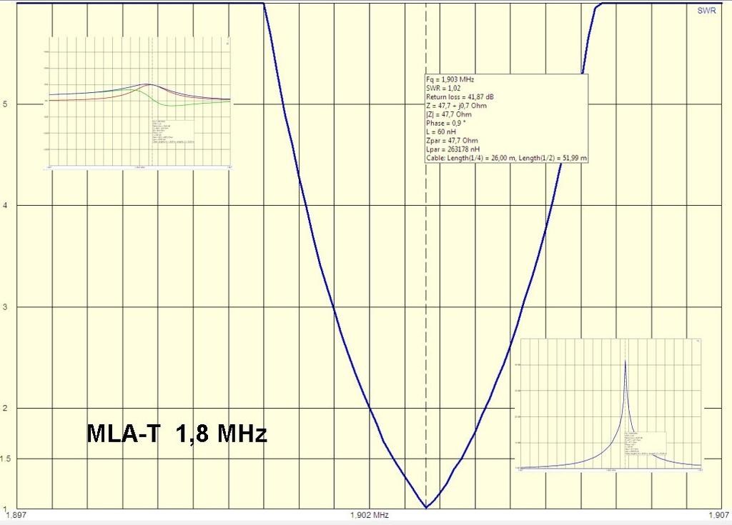
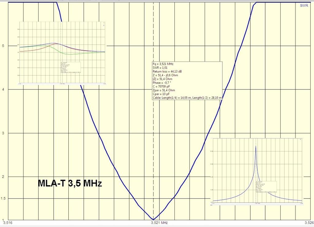
6 page 5 Measurement protocols fig. 7 fig. 8

7 page 6 Measurement protocols fig. 9
Magnetic Loop Antenna - Topbands
 Magnetic Loop Antenna - Topbands Instruction Manual Thank you for purchasing this new product small Magnetic Loop Antenna Topbands. Manual contains important information. Please read all instructions carefully
Magnetic Loop Antenna - Multiband
 Magnetic Loop Antenna - Multiband Instruction Manual Thank you for purchasing this new product small Magnetic Loop Antenna Multiband. Manual contains important information. Please read all instructions
Users Manual. 200W HF/50MHz Band Auto Antenna Tuner. Model HC-200AT
 Users Manual 200W HF/50MHz Band Auto Antenna Tuner Model HC-200AT Caution 1. Never remove or open the tuner cover while transmitting. When there is RF in the circuits of the tuner, there will be high voltage
4/29/2012. General Class Element 3 Course Presentation. Ant Antennas as. Subelement G9. 4 Exam Questions, 4 Groups
 General Class Element 3 Course Presentation ti ELEMENT 3 SUB ELEMENTS General Licensing Class Subelement G9 Antennas and Feedlines 4 Exam Questions, 4 Groups G1 Commission s Rules G2 Operating Procedures
Milton Keynes Amateur Radio Society (MKARS)
") Milton Keynes Amateur Radio Society (MKARS) Intermediate Licence Course Feeders Antennas Matching (Worksheets 31, 32 & 33) MKARS Intermediate Licence Course - Worksheet 31 32 33 Antennas Feeders Matching
Milton Keynes Amateur Radio Society (MKARS) Intermediate Licence Course Feeders Antennas Matching (Worksheets 31, 32 & 33) MKARS Intermediate Licence Course - Worksheet 31 32 33 Antennas Feeders Matching
MFJ-941E Versa Tuner II GENERAL INFORMATION:
 GENERAL INFORMATION: MFJ VERSA TUNER II The MFJ-941E is designed to match virtually any transmitter to any antenna, including dipoles, inverted-vees, verticals, mobile whips, beams, random wires, and others
REIMESCH KOMMUNIKATIONSSYSTEME GMBH ALPIN HF Linear Amplifier - USER MANUAL. v1.0
 REIMESCH KOMMUNIKATIONSSYSTEME GMBH ALPIN 200 - HF Linear Amplifier - USER MANUAL v1.0 DECLARATION OF CONFORMITY I hereby declare that the product: ALPIN 200, HF 2kW Linear Amplifier satisfies all the
4 Antennas as an essential part of any radio station
 4 Antennas as an essential part of any radio station 4.1 Choosing an antenna Communicators quickly learn two antenna truths: Any antenna is better than no antenna. Time, effort and money invested in the
Technician License. Course
 Technician License Course Technician License Course Chapter 4 Lesson Plan Module - 9 Antenna Fundamentals Feed Lines & SWR The Antenna System The Antenna System Antenna: Transforms current into radio waves
1.5 kw Automatic Remote Controlled Antenna Tuner for Verticals and other Unbalanced Antennas
 1.5 kw Automatic Remote Controlled Antenna Tuner for Verticals and other Unbalanced Antennas Mod. AT- 615U Short Form Manual 10/2010 Dipl.Ing. Klaus Bemmerer RF Communication Electronics Niendorf-Middeldor
REIMESCH KOMMUNIKATIONSSYSTEME GMBH ALPIN HF / 50MHz Linear Amplifier - USER MANUAL. v1.1
 REIMESCH KOMMUNIKATIONSSYSTEME GMBH ALPIN 100 - HF / 50MHz Linear Amplifier - USER MANUAL v1.1 DECLARATION OF CONFORMITY I hereby declare that the product: ALPIN 100, HF/6m 1kW Linear Amplifier satisfies
Antennas and Propagation Chapters T4, G7, G8 Antenna Fundamentals, More Antenna Types, Feed lines and Measurements, Propagation
 Antennas and Propagation Chapters T4, G7, G8 Antenna Fundamentals, More Antenna Types, Feed lines and Measurements, Propagation =============================================================== Antenna Fundamentals
Chapter 5.0 Antennas Section 5.1 Theory & Principles
 Chapter 5.0 Antennas Section 5.1 Theory & Principles G3C11 (B) p.135 Which of the following antenna types will be most effective for skip communications on 40-meters during the day? A. A vertical antenna
MFJ-949E. tuner antenowy skrzynka antenowa. Instrukcja obsługi. importer:
 Instrukcja obsługi MFJ-949E tuner antenowy skrzynka antenowa importer: PRO-FIT Centrum Radiokomunikacji InRadio ul. Puszkina 80 92-516 Łódź tel: 42 649 28 28 e-mail: biuro@inradio.pl www.inradio.pl MFJ-949E
ALWAYS ATTACH THE SAFETY ROPE TO A STABLE SUPPORT BEFORE ATTEMPTING TO ATTACH THE UNIVERSAL MOUNT TO A WINDOW FRAME OR RAIL.
 MFJ-1623 Introduction The MFJ-1623 was designed to provide portable or permanent HF communications on 30 through 10 meters and VHF on 6 meters. The universal mount design allows the user to install the
MFJ-219/219N 440 MHz UHF SWR Analyzer TABLE OF CONTENTS
 MFJ-219/219N 440 MHz UHF SWR Analyzer TABLE OF CONTENTS Introduction...2 Powering The MFJ-219/219N...3 Battery Installation...3 Operation Of The MFJ-219/219N...4 SWR and the MFJ-219/219N...4 Measuring
RX Directional Antennas. Detuning of TX Antennas.
 1. Models Impact of Resonant TX antennas on the Radiation Pattern of RX Directional Antennas. Detuning of TX Antennas. Chavdar Levkov, lz1aq@abv.bg, www.lz1aq.signacor.com 2-element small loops and 2-element
SWR myths and mysteries.
 SWR myths and mysteries. By Andrew Barron ZL3DW September 2012 This article will explain some of the often misunderstood facts about antenna SWR at HF and uncover some popular misconceptions. The questions
CAVITY TUNING. July written by Gary Moore Telewave, Inc. 660 Giguere Court, San Jose, CA Phone:
 CAVITY TUNING July 2017 -written by Gary Moore Telewave, Inc 660 Giguere Court, San Jose, CA 95133 Phone: 408-929-4400 1 P a g e Introduction Resonant coaxial cavities are the building blocks of modern
JC-5 4KW PEP, 1KW RMS AUTO ANTENNA COUPLER
 JC-5 4KW PEP, 1KW RMS AUTO ANTENNA COUPLER 1) DIRECTLY CONTROLLED BY ICOM, ALINCO & KENWOOD. 2) INDEPENDENT CAPACITOR INPUT AND OUTPUT BLOCKS! 3) 3 mm COIL WIRE & INTERNAL FAN FOR THE BIG COILS! 4) DIPPED
MFJ-249B HF/VHF SWR ANALYZER
 TABLE OF CONTENTS MFJ-249B... 2 Introduction... 2 Powering The MFJ-249B... 3 Battery Installation... 3 Alkaline Batteries... 3 NiCd Batteries... 4 Power Saving Mode... 4 Operation Of The MFJ-249B...5 SWR
Instruction Manual OM3500 HF SHORTWAVE POWER AMPLIFIER. OM POWER, s. r. o Bác 126 SLOVAKIA
 Instruction Manual OM3500 HF SHORTWAVE POWER AMPLIFIER OM POWER, s. r. o. 930 30 Bác 126 SLOVAKIA Important safety instructions: The amplifier contains high voltage circuits. Never turn the amplifier on
One I had narrowed the options down, I installed some wire and started testing.
 Loft & Attic antennas for restricted spaces - M. Ehrenfried G8JNJ I ve recently been looking at designs for an efficient antenna that would fit in a loft. I hoped to find something that would work on with
BARRETT. 911 Automatic antenna tuner Installation instructions. General. Specifications COMMUNICATIONS
 BARRETT COMMUNICATIONS 0 0 0 Automatic antenna tuner Installation instructions Diameter = mm Connection 0 BARRETT AUTOMATIC ANTENNA TUNER General 0 Control Cable Gland Ground Connection The Barrett Automatic
Chapter 6 Antenna Basics. Dipoles, Ground-planes, and Wires Directional Antennas Feed Lines
 Chapter 6 Antenna Basics Dipoles, Ground-planes, and Wires Directional Antennas Feed Lines Some General Rules Bigger is better. (Most of the time) Higher is better. (Most of the time) Lower SWR is better.
COAXIAL TRANSMISSION LINE COMMON-MODE CURRENT
 COAXIAL TRANSMISSION LINE COMMON-MODE CURRENT Introduction Coaxial transmission lines are popular for their wide frequency bandwidth and high resistance to electromagnetic interference (EMI). Coax cables
Improved Ionospheric Propagation With Polarization Diversity, Using A Dual Feedpoint Cubical Quad Loop
 Improved Ionospheric Propagation With Polarization Diversity, Using A Dual Feedpoint Cubical Quad Loop by George Pritchard - AB2KC ab2kc@optonline.net Introduction This Quad antenna project covers a practical
Sometimes for grounded antennas is used a usual horizontal dipole antenna located straight over the ground. Page-16
 Chapter from the book: Alpert, Bulatov, Runge: Antennas of the Third Reich: Published by Ministry of Defense of the USSR, Moscow, 1948. (Circulation: 300 copies). Credit line: http://www.radioscanner.ru/files/antennas/file10355/
Small Magnetic Loops: A Beginner s Guide WOW! This is a very different antenna!
 Small Magnetic Loops: A Beginner s Guide WOW! This is a very different antenna! Dave Wickert, AE7TD Lake Washington Ham Club November 2018 Meeting 10-Nov-2018 Dayton Hamvention 2017 History Full Size Loops
Portable Magnetic Loop Antenna. KG5EAO Rick Bono
 Portable Magnetic Loop Antenna KG5EAO Rick Bono April 2, 2016 Overview Develop a Portable magnetic loop antenna for use on HF bands running QRP. Portable and easy to deploy Ideally run on the 40m through
The Amazing MFJ 269 Author Jack Tiley AD7FO
 The Amazing MFJ 269 Author Jack Tiley AD7FO ARRL Certified Emcomm and license class Instructor, Volunteer Examiner, EWA Technical Coordinator and President of the Inland Empire VHF Club What Can be Measured?
MODERN AM BROADCAST STATIONS AM STEREO CQUAM WITH DDS
 MODERN AM BROADCAST STATIONS AM STEREO CQUAM WITH DDS DDS EXCITER OPERATING MANUAL 20W CARRIER - 80W PEP WHAT IS DDS? IT IS THE INITIALS OF THE WORDS DIRECT DIGITAL SYNTHESIZER. THAT MEANS: DIRECT DIGITAL
FBK portable mini tuner
 FBK portable mini tuner tunes symmetric/coax/longwire antenna's between 1.8-50MHz When possible it is always preferred to use a full sized antenna, especially when using low powered portable transceivers
MFJ-969 Versa Tuner II Instruction Manual
 MFJ-969 Versa Tuner II Instruction Manual General Information The MFJ-969 is a 300 watt RF output power antenna tuner that will match any transmitter or transceiver to virtually any antenna. Peak or average
Portable Dipole Shortwave Antenna (PDSA-7)
") PACKING LIST 1 Connection base 1 (Material: Nylon) 2 Multiband loading coil 2 (40m-10m, material: Nylon) 3 Aluminum oxide tube 4 (19 X 280mm) 4 Extractable antenna (on the top) 2 (Each fully extracted
PACKING LIST 1 Connection base 1 (Material: Nylon) 2 Multiband loading coil 2 (40m-10m, material: Nylon) 3 Aluminum oxide tube 4 (19 X 280mm) 4 Extractable antenna (on the top) 2 (Each fully extracted
VECTRONICS. VC-300DLP Antenna Tuner
 VECTRONICS VC-300DLP Antenna Tuner FEATURES The Vectronics VC-300DLP Antenna Tuner optimizes the performance of your antenna and transmitter, receiver, or transceiver by providing adjustable impedance
CHAPTER 8 ANTENNAS 1
 CHAPTER 8 ANTENNAS 1 2 Antennas A good antenna works A bad antenna is a waste of time & money Antenna systems can be very inexpensive and simple They can also be very expensive 3 Antenna Considerations
Amateur Radio License. Propagation and Antennas
 Amateur Radio License Propagation and Antennas Todays Topics Propagation Antennas Propagation Modes Ground wave Low HF and below, ground acts as waveguide Line-of-Sight (LOS) VHF and above, radio waves
Technician License Course Chapter 4. Lesson Plan Module 9 Antenna Fundamentals, Feed Lines & SWR
 Technician License Course Chapter 4 Lesson Plan Module 9 Antenna Fundamentals, Feed Lines & SWR The Antenna System Antenna: Transforms current into radio waves (transmit) and vice versa (receive). Feed
mat-30 HF-SSB Automatic Antenna Tuner Instruction Manual Version V1.0
 INTRODUCTION mat-30 HF-SSB Automatic Antenna Tuner Instruction Manual Version V1.0 The mat-30 is an automatic tuner intended for use with modern Yaesu transceivers. It works with some Yaesu transceiver
Technician Licensing Class T9
 Technician Licensing Class T9 Amateur Radio Course Monroe EMS Building Monroe, Utah January 11/18, 2014 January 22, 2014 Testing Session Valid dates: July 1, 2010 June 30, 2014 Amateur Radio Technician
ANTENNAS. I will mostly be talking about transmission. Keep in mind though, whatever is said about transmission is true of reception.
 Reading 37 Ron Bertrand VK2DQ http://www.radioelectronicschool.com ANTENNAS The purpose of an antenna is to receive and/or transmit electromagnetic radiation. When the antenna is not connected directly
1) Transmission Line Transformer a. First appeared on the scene in 1944 in a paper by George Guanella as a transmission line transformer, the 1:1
 Transmission Line Transformer a. First appeared on the scene in 1944 in a paper by George Guanella as a transmission line transformer, the 1:1") 1) Transmission Line Transformer a. First appeared on the scene in 1944 in a paper by George Guanella as a transmission line transformer, the 1:1 Guanella Balun is the basic building Balun building block.
1) Transmission Line Transformer a. First appeared on the scene in 1944 in a paper by George Guanella as a transmission line transformer, the 1:1 Guanella Balun is the basic building Balun building block.
Optimizing Your Stations Performance
 Optimizing Your Stations Performance A few hints / techniques, recommendations for getting the most RF out to the Antenna from your HF, VHF / UHF station. Tonights Presenters: Doug Theriault NO1D John
QUICK REFERENCE GUIDE
 QUICK REFERENCE GUIDE Installation 1. Install a ground system for DC noise suppression and RFI suppression 2. Install your DC power supply 3. Install lightning protection. This will help protect more than
Introduction LOADING COIL COUNTERPOISE ATTACHMENT ANTENNA ATTACHMENT. Figure 1: MFJ-1625 Window/Balcony Mount Antenna
 Introduction MFJ-1625 The MFJ-1625 is a 200 Watt antenna tuner that was designed to provide portable or permanent HF communications on 80 through 10 meters and VHF on 6 meters. The universal mount design
Intermediate Course (5) Antennas and Feeders
 Antennas and Feeders") Intermediate Course (5) Antennas and Feeders 1 System Transmitter 50 Ohms Output Standing Wave Ratio Meter Antenna Matching Unit Feeder Antenna Receiver 2 Feeders Feeder types: Coaxial, Twin Conductors
Intermediate Course (5) Antennas and Feeders 1 System Transmitter 50 Ohms Output Standing Wave Ratio Meter Antenna Matching Unit Feeder Antenna Receiver 2 Feeders Feeder types: Coaxial, Twin Conductors
Portable HF Magnetic Loop Antenna System Model HF-315
 Portable HF Magnetic Loop Antenna System Model HF-315 Contents: Introduction... 2 Safety information... 3 Warranty information... 4 Assembling and using your antenna... 5 Illustrations... 6 Specifications...
FCC Technician License Course
 FCC Technician License Course 2014-2018 FCC Element 2 Technician Class Question Pool Presented by: Tamiami Amateur Radio Club (TARC) WELCOME To the third of 4, 3-hour classes presented by TARC to prepare
CON NEX HP. OWNER'S MANUAL Full Channel AM/FM Amateur Mobile Transceiver TABLE OF CONTENTS TUNING THE ANTENNA FOR OPTIMUM S.W.R..
 TABLE OF CONTENTS PAGE SPECIFICATIONS... 2 INSTALLATION... 3 LOCATION... 3 CON NEX - 4300HP MOUNTING THE RADIO... 3 IGNITION NOISE INTERFERENCE... 4 ANTENNA... 4 TUNING THE ANTENNA FOR OPTIMUM S.W.R..
Introduction. Understanding Power Ratings. Peak Reading SWR/Wattmeter
 Introduction The MFJ-962D is a "T" network roller inductor tuner with built-in antenna switching, RF power and SWR metering and a 1:1 balun. The largest amplifiers that can safely be used include the Heathkit
18-CHANNEL MOBILE CB TRANSCEIVER MODEL CB-845
 18-CHANNEL MOBILE CB TRANSCEIVER MODEL CB-845 INSTRUCTION HANDBOOK RAll JEFFERSOn CITIZEN BAND RADIO MESSAGE TO THE OWNER CONGRATULATIONS! As the new owner of Ray Jefferson Model CB-845 CB Mobile Transceiver,
Technician License. Course
 Technician License Course Technician License Course Chapter 4 Lesson Plan Module - 10 Practical Antennas The Dipole Most basic antenna The Dipole Most basic antenna The Dipole Total length is ½ wavelength
Cray Valley Radio Society. Real Life Wire Antennas
 Cray Valley Radio Society Real Life Wire Antennas 1 The basic dipole The size of an antenna is determined by the wavelength of operation In free space: ~3x10 8 m/s Frequency x Wavelength = Speed of Light,
Miniature Magnetic Loops By David Posthuma, WD8PUO
 Miniature Magnetic Loops By David Posthuma, WD8PUO Application Notes and Articles A General Overview After several years of curiosity and several months of research, I recently built two magnetic loops.
MFJ 259 Operation & Simplified Calibration
 MFJ 259 Operation & Simplified Calibration Bill Leonard N0CU NA0TC 2014 TechFest 1 What Will Be Covered Part 1: Operation What is an MFJ 259 What Does It Measure Impedance & Admittance How Does It Work
MFJ-945E. tuner antenowy skrzynka antenowa. Instrukcja obsługi. importer:
 Instrukcja obsługi MFJ-945E tuner antenowy skrzynka antenowa importer: PRO-FIT Centrum Radiokomunikacji InRadio ul. Puszkina 80 92-516 Łódź tel: 42 649 28 28 e-mail: biuro@inradio.pl www.inradio.pl MFJ-945E
MFJ Balanced Line Tuner
 MFJ Balanced Line Tuner Introduction The MFJ-974H balanced line antenna tuner is a fully balanced true balanced line antenna tuner, providing superb current balance throughout a very wide matching range
An Introduction to Radio Frequency Interference
 An Introduction to Radio Frequency Interference Ron Hranac, N0IVN Member, ARRL EMC Committee ARRL Colorado Section Technical Specialist What is RFI? RFI is an abbreviation for radio frequency interference
USERS MANUAL for the. FB5 Antenna. a personal non-commercial project of the Florida Boys
 USERS MANUAL for the FB5 Antenna a personal non-commercial project of the Florida Boys AB4ET Dec.2003 1 The FB5 Antenna USERS MANUAL INDEX 1.0. Introduction 2.0. Design 3.0. Construction 4.0. Electrical
Amateur Extra Manual Chapter 9.4 Transmission Lines
 9.4 TRANSMISSION LINES (page 9-31) WAVELENGTH IN A FEED LINE (page 9-31) VELOCITY OF PROPAGATION (page 9-32) Speed of Wave in a Transmission Line VF = Velocity Factor = Speed of Light in a Vacuum Question
Antenna Design for FM-02
 Antenna Design for FM-02 I recently received my FM-02 FM transmitter which I purchased from WLC. I researched the forum on what antennas where being used by the DIY community and found a nice write-up
Trees, vegetation, buildings etc.
 EMC Measurements Test Site Locations Open Area (Field) Test Site Obstruction Free Trees, vegetation, buildings etc. Chamber or Screened Room Smaller Equipments Attenuate external fields (about 100dB) External
4/25/2012. Supplement T9. 2 Exam Questions, 2 Groups. Amateur Radio Technician Class T9A: T9A: T9A: T9A:
 Amateur Radio Technician Class Element 2 Course Presentation ti ELEMENT 2 SUB-ELEMENTS Technician Licensing Class Supplement T9 Antennas, Feedlines 2 Exam Questions, 2 Groups T1 - FCC Rules, descriptions
Compact Multi-Band Rotatable Dipole Antenna Array
 Compact Multi-Band Rotatable Dipole Antenna Array Dr. John A. Allocca, WB2LUA, www.wb2lua.com, 4/9/12 Introduction Having limited space led to the design of this multi-band antenna array, which has a foot
Vectronics VC-300D DIGITAL BARGRAPH ANTENNA TUNER
 Vectronics VC-300D DIGITAL BARGRAPH ANTENNA TUNER FEATURES The Vectronics VC-300D Antenna Tuner optimizes the performance of your antenna and transmitter, receiver, or transceiver by providing adjustable
INSTALLATION AND CONNECTIONS Section 2
 STLLTION ND CONNECTIONS Section Unpacking - ntenna jumper cable connection - Selecting a location - Rack mounting handle attachment - Grounding -3 ntenna connection -3 CF (Compact Flash) memory card -3
AM/FM SYNTHESIZER TUNER
 OPERATING INSTRUCTIONS AM/FM SYNTHESIZER TUNER DT-930 UL TABLE OF CONTENTS 1. IMPORTANT SAFETY INSTRUCTIONS... 2 2. SAFETY PRECAUTIONS... 2 3. INFORMATION TO THE USER... 3 4. GENERAL DESCRIPTION... 3 5.
Dressler ARA-2000 active antenna what s inside?
 Dressler ARA-2000 active antenna what s inside? Matthias Bopp Updated October 23 rd 2011 Dressler active antennas have an excellent reputation and thus I was interested how they are comprised before buying
mat-180h HF-SSB Automatic Antenna Tuner Instruction Manual Version V1.0
 INTRODUCTION mat-180h HF-SSB Automatic Antenna Tuner Instruction Manual Version V1.0 The mat-180h is an automatic tuner intended for use with modern Icom transceivers. It works with any Icom transceiver
Technician Licensing Class. Antennas
 Technician Licensing Class Antennas Antennas A simple dipole mounted so the conductor is parallel to the Earth's surface is a horizontally polarized antenna. T9A3 Polarization is referenced to the Earth
i. AM. Radio Transmitter Installation and Operation Easy to follow instructions on how to program and use your Model 5.0 i. AM.
 i. AM. Radio Transmitter Installation and Operation Easy to follow instructions on how to program and use your Model 5.0 i. AM. Radio Transmitter Contents Quick Start...3 Front and Rear Panel Controls...5
MFJ-1026 MFJ Deluxe Noise Canceling Signal Enhancer Instruction Manual
 Introduction MFJ-1026 MFJ Instruction Manual To get the best performance from your MFJ-1026, read this manual. It is especially important to heed all warnings to prevent equipment damage. The MFJ-1026
RigExpert AA-170 Antenna Analyzer (0.1 to 170 MHz) User s manual
 User s manual") RigExpert AA-170 Antenna Analyzer (0.1 to 170 MHz) User s manual Table of contents 1. Description... 3 2. Specifications... 4 3. Precautions... 5 4. Operation... 6 4.1. Preparation for use... 6 4.2. Turning
RigExpert AA-170 Antenna Analyzer (0.1 to 170 MHz) User s manual Table of contents 1. Description... 3 2. Specifications... 4 3. Precautions... 5 4. Operation... 6 4.1. Preparation for use... 6 4.2. Turning
1997 MFJ ENTERPRISES, INC.
 INSTRUCTION MANUAL CAUTION: Read All Instructions Before Operating Equipment MFJ ENTERPRISES, INC. 300 Industrial Park Road Starkville, MS 39759 USA Tel: 601-323-5869 Fax: 601-323-6551 VERSION 6C COPYRIGHT
Least understood topics by most HAMs RF Safety Ground Antennas Matching & Feed Lines
 Least understood topics by most HAMs RF Safety Ground Antennas Matching & Feed Lines Remember this question from the General License Exam? G0A03 (D) How can you determine that your station complies with
CONNECTING THE PROBE TO THE TEST INSTRUMENT
 2SHUDWLRQ 2SHUDWLRQ Caution The input circuits in the AP034 Active Differential Probe incorporate components that protect the probe from damage resulting from electrostatic discharge (ESD). Keep in mind
RFID. Technical Training. Low Frequency Antenna Design. J.A.G Jan 2009 Texas Instruments Proprietary Information 1
 Technical Training Low Frequency Antenna Design J.A.G Jan 2009 Texas Instruments Proprietary Information 1 Custom Antenna Design There are many reasons why integrators may wish to make their own Low Frequency
HLV Instruction & Operations Manual. Content
 HLV-800-3 Instruction & Operations Manual Content 1 Chapter page 1. Certificate of conformity 3 2. Introduction 4 3. Safety instructions 5 4. Electrical connections 6 5. Warranty 7 6. Front panel operation
Chapter 12: Transmission Lines. EET-223: RF Communication Circuits Walter Lara
 Chapter 12: Transmission Lines EET-223: RF Communication Circuits Walter Lara Introduction A transmission line can be defined as the conductive connections between system elements that carry signal power.
MFJ-904. tuner antenowy skrzynka antenowa. Instrukcja obsługi. importer:
 Instrukcja obsługi MFJ-904 tuner antenowy skrzynka antenowa importer: PRO-FIT Centrum Radiokomunikacji InRadio ul. Puszkina 80 92-516 Łódź tel: 42 649 28 28 e-mail: biuro@inradio.pl www.inradio.pl INTRODUCTION
Array Solutions Four Square Array Manual and User s Guide
 Array Solutions Four Square Array Manual and User s Guide Array Solutions Four Square Array Pattern Steering System Congratulations! You have selected one of the finest phased array steering systems made.
End Fed Half Wave Antenna Coupler
 End Fed Half Wave Antenna Coupler The finished End Fed Half Wave antenna coupler. Centre fed half wave dipoles make great, simple and effective antennas for the HF bands. Sometimes however, the centre
Receive Antenna Phasing Controller DXE-NCC-2
 Receive Antenna Phasing Controller DXE-NCC-2 DXE-NCC-2-INS Rev 1b DX Engineering 2017 1200 Southeast Ave. - Tallmadge, OH 44278 USA Phone: (800) 777-0703 Tech Support and International: (330) 572-3200
1.5 kw Automatic Remote Controlled Balanced Antenna Tuner. Model AT- 615B. Short Form Manual
 1.5 kw Automatic Remote Controlled Balanced Antenna Tuner Model AT- 615B Short Form Manual 10/2010 Dipl.Ing. Klaus Bemmerer RF Communication Electronics Niendorf-Middeldor 11 23769 Fehmarn GERMANY Phone
ANC-4. ANTENNA NOISE CANCELLER for Reducing Locally-Generated Noise. Instruction Manual
 ANC-4 ANTENNA NOISE CANCELLER for Reducing Locally-Generated Noise Instruction Manual Revision 2.0 May 2, 2000 WARRANTY WHO IS COVERED WHAT WE WILL DO WHAT YOU MUST DO WHAT IS NOT COVERED SERVICE WARRANTY
Transmission lines. Characteristics Applications Connectors
 Transmission lines Characteristics Applications Connectors Transmission Lines Connect They allow us to conduct RF Signals between our station components, they connect: Transceivers Antennas Tuners Amplifiers
DISCLAIMER user purposes only not not
 DISCLAIMER Information in this manual is designed for user purposes only and is not intended to supersede information contained in customer regulations, technical manuals/documents, positional handbooks,
LDG TW-1 Talking Wattmeter
 LDG TW-1 Talking Wattmeter LDG Electronics 1445 Parran Road, PO Box 48 St. Leonard MD 20685-2903 USA Phone: 410-586-2177 Fax: 410-586-8475 ldg@ldgelectronics.com www.ldgelectronics.com 1 LDG TW-1 Talking
MODERN AM BROADCAST STATIONS
 MODERN AM BROADCAST STATIONS With DDS DDS EXCITER OPERATING MANUAL 75w carrier - 300w p.e.p What is DDS IT IS THE INITIALS OF THE WORDS DIRECT DIGITAL SYNTHESIZER, THAT MEANS: DIRECT DIGITAL FREQUENCY
Last year I described several Low Band RX antennas that would enable you to hear DX stations on 160, 80 and 40M. This will show you how to build
 Last year I described several Low Band RX antennas that would enable you to hear DX stations on 160, 80 and 40M. This will show you how to build transmit antennas that will help you break the pileups!
TMP40. User Manual.
 TMP40 User Manual www.audac.eu ADDITIONAL INFORMATION This manual is put together with much care, and is as complete as could be on the publication date. However, updates on the specifications, functionality
AA-35 ZOOM. RigExpert. User s manual. Antenna and cable analyzer
 AA-35 ZOOM Antenna and cable analyzer RigExpert User s manual . Table of contents Introduction Operating the AA-35 ZOOM First time use Main menu Multifunctional keys Connecting to your antenna SWR chart
Portable Antenna Spike Mount (CHA SPIKE MOUNT) Operator s Manual
 Operator s Manual") Portable Antenna Spike Mount (CHA SPIKE MOUNT) Operator s Manual Nevada - USA WWW.CHAMELEONANTENNA.COM VERSATILE DEPENDABLE STEALTH BUILT TO LAST Table of Contents Introduction... 3 Parts of the Spike
Portable Antenna Spike Mount (CHA SPIKE MOUNT) Operator s Manual Nevada - USA WWW.CHAMELEONANTENNA.COM VERSATILE DEPENDABLE STEALTH BUILT TO LAST Table of Contents Introduction... 3 Parts of the Spike
Port P able ort Magnet Magne ic Loop Ant An e t nna KG5EAO Rick Bono August Augus 11, 2015
 Portable Magnetic Loop Antenna KG5EAO Rick Bono August 11, 2015 Overview Develop a portable magnetic loop antenna for use on HF bands running QRP. Easy to deploy Ideally run on 40m through 10m bands For
Beverage Antenna. Theoretical Look on Practical Result.
 Beverage Antenna. Theoretical Look on Practical By: Igor Grigorov, VA3ZNW My Beverage Antenna (Figure 1, that was described at: http:///019/va3znw_019.htm ) is successfully working at my station. The antenna
Active Antennas 4/28/2017
 1 Active Antenna??? What Why Theory Loops Verticals Dipoles Amplifier Considerations VE7KW experiments 2 What Simply an antenna with an amplifier - Automotive application - My first exposure to active
Guide. Installation. Wilson Electronics, Inc. Direct Connection High Power iden Amplifi er 800 MHz Band. Contents:
 Amplifier Installation Guide Direct Connection High Power iden Amplifi er 800 MHz Band Contents: Guarantee and Warranty 1 Before Getting Started / How it Works 3 Installing a Wilson Outside Antenna - In-Vehicle
Remote Controller. (Controller: Provided in kit form) * Power Supply Required: Approx. 13VDC 0.2~0.4A (Not Required for CD160Jr)
 * Power Supply Required: Approx. 13VDC 0.2~0.4A (Not Required for CD160Jr)") 1.8MHz(3-CH),1.9MHz(1-CH) 1.8/1.9MHz Super-Compact Dipole Antenna CD160-x, CD160L Model CD160 Antenna Tuning Unit BS83 Remote Controller (Controller: Provided in kit form) * Power Supply Required: Approx.
1.8MHz(3-CH),1.9MHz(1-CH) 1.8/1.9MHz Super-Compact Dipole Antenna CD160-x, CD160L Model CD160 Antenna Tuning Unit BS83 Remote Controller (Controller: Provided in kit form) * Power Supply Required: Approx.
Basic Wire Antennas. Part II: Loops and Verticals
 Basic Wire Antennas Part II: Loops and Verticals A loop antenna is composed of a single loop of wire, greater than a half wavelength long. The loop does not have to be any particular shape. RF power can