beginning with version 1.01
|
|
|
- Anis Carr
- 6 years ago
- Views:
Transcription

1 DeltaTherm HC mini beginning with version 1.01 Heating controller Manual for the specialised craftsman Mounting Connection Operation Troubleshooting Application examples * * Adjust your heating via app Thank you for buying this RESOL product. Please read this manual carefully to get the best performance from this unit. Please keep this manual carefully. en Manual
2 en Safety advice Please pay attention to the following safety advice in order to avoid danger and damage to people and property. Instructions Attention must be paid to the valid local standards, regulations and directives! Information about the product Proper usage The controller is designed for use in heating systems in compliance with the technical data specified in this manual. Improper use excludes all liability claims. CE-Declaration of conformity The product complies with the relevant directives and is therefore labelled with the CE mark. The Declaration of Conformity is available upon request, please contact RESOL. Target group These instructions are exclusively addressed to authorised skilled personnel. Only qualified electricians should carry out electrical works. Initial installation must be effected by the system owner or qualified personnel named by the system owner. Description of symbols WARNING! Warnings are indicated with a warning triangle! They contain information on how to avoid the danger described. Signal words describe the danger that may occur, when it is not avoided. WARNING means that injury, possibly life-threatening injury, can occur. ATTENTION means that damage to the appliance can occur. Note: Notes are indicated with an information symbol. Arrows indicate instruction steps that should be carried out. Note: Strong electromagnetic fields can impair the function of the device. Make sure the device as well as the system are not exposed to strong electromagnetic fields. Disposal Dispose of the packaging in an environmentally sound manner. Dispose of old appliances in an environmentally sound manner. Upon request we will take back your old appliances bought from us and guarantee an environmentally sound disposal of the devices. Subject to technical change. Errors excepted _ _DeltaTherm_HC_mini.monen.indd 2
3 DeltaTherm HC mini Heating controller The DeltaTherm HC mini offers a compact and user-friendly solution for simple heating systems. It can control a weather-compensated heating circuit and its backup heating demand. Additionally, there s a choice of 5 different operating modes, a boiler protection option and a night correction. Due to the commissioning menu and the 4 pre-configured basic systems, configuration is quick and easy. The chimney sweeper function and the holiday mode can be activated by pressing a single button. en Contents 1 Overview Installation Mounting Electrical connection Data communication / Bus MicroSD card slot Operation and function Buttons and adjustment dial Microbutton for chimney sweeper function / screed drying and holiday mode Control lamp Commissioning Schemes with basic settings ErP temperature controls classes Functions and options Menu structure Status menu Heating Meas. / Balance values Messages Heating Shared relays Heating circuit Screed drying Basic settings SD card Manual mode User code In- / Outputs Inputs Outputs Troubleshooting Accessories Sensors and measuring instruments VBus accessories Interface adapters Index
4 en 1 Overview 4 pre-configured basic systems 12 pre-programmed schemes for the temperature controls classes II, III, V, VI, VII and VIII 4 relay outputs (incl. 1 extra-low voltage relay) 5 inputs for Pt1000 temperature sensors 5 operating modes, boiler protection, room thermostat and night correction Chimney sweeper function, screed drying function and holiday mode via microbuttons Holiday mode, chimney sweeper function and screed drying function via microbuttons Data logging, storing, easy transfer of controller adjustments prepared and firmware updates via SD card Modulating heating control with 0-10 V boiler control Weather-compensated control with room influence or demand-based room control with up to 3 room temperature sensors Remote access with a room control unit or the VBus Touch HC App Upper fastening Lower fastening Technical data Inputs: 5 inputs for Pt1000 temperature sensors (1 of them can be converted to Switch and one of them to RTA remote control or BAS operating mode switch) Outputs: 3 semiconductor relays, 1 potential-free extra-low voltage relay, 1 PWM output, V output PWM frequency: 512 Hz PWM voltage: 10.8 V Switching capacity: 1 (1) A 240 V~ (semiconductor relay) 1 (1) A 30 V (potential-free relay) Total switching capacity: 3 A 240 V~ Power supply: V~ (50 60 Hz) Supply connection: type Y attachment Standby: 0.63W Temperature controls class: VIII Energy efficiency contribution: 5 % Mode of operation: type 1.B.C.Y action Rated impulse voltage: 2.5 kv Data interface: VBus, MicroSD card slot VBus current supply: 60 ma Functions: weather-compensated heating circuit control, backup heating, room thermostat, chimney sweeper function, screed drying function, holiday mode Housing: plastic, PC-ABS and PMMA Mounting: wall mounting, also suitable for mounting into patch panels Indication / Display: full graphic display, control lamp (Lightwheel ) Operation: 4 push buttons at the front and 1 Lightwheel Protection type: IP 20 / DIN EN Protection class: I Ambient temperature: 0 40 C Degree of pollution: 2 Dimensions: 110 x 166 x 47 mm 110 4
5 2 Installation 2.1 Mounting WARNING! Electric shock! Upon opening the housing, live parts are exposed! Always disconnect the controller from power supply before opening the housing! Note: Strong electromagnetic fields can impair the function of the device. Make sure the device as well as the system are not exposed to strong electromagnetic fields. The unit must only be located in dry interior rooms. The controller must additionally be supplied from a double pole switch with contact gap of at least 3 mm. Please pay attention to separate routing of sensor cables and mains cables. In order to mount the device to the wall, carry out the following steps: Unscrew the crosshead screw from the cover and remove it along with the cover from the housing. Mark the upper fastening point on the wall. Drill and fasten the enclosed wall plug and screw leaving the head protruding. Hang the housing from the upper fastening point and mark the lower fastening point (centres 130 mm). Insert lower wall plug. Fasten the housing to the wall with the lower fastening screw and tighten. Carry out the electrical wiring in accordance with the terminal allocation (see page 5). Put the cover on the housing. Attach with the fastening screw. 2.2 Electrical connection WARNING! Electric shock! Upon opening the housing, live parts are exposed! Always disconnect the controller from power supply before opening the housing! ATTENTION! ESD damage! Electrostatic discharge can lead to damage to electronic components! Take care to discharge properly before touching the inside of the device! To do so, touch a grounded surface such as a radiator or tap! Note: Connecting the device to the power supply must always be the last step of the installation! Note: The pump speed must be set to 100 % when auxiliary relays or valves are connected. Note: It must be possible to disconnect the device from the mains at any time. Install the mains plug such that it is accessible at any time. If this is not possible, install a switch that can be accessed. Do not use the device if it is visibly damaged! Depending on the product version, cables are already connected to the device. If that is not the case, please proceed as follows: The controller is equipped with 4 relays in total to which loads such as pumps, valves, etc. can be connected: Relays 1 3 are semiconductor relays, designed for pump speed control: Conductor R1 R3 Neutral conductor N (common terminal block) Protective earth conductor (common terminal block) Relay 4 is a potential-free extra-low voltage relay: Connections to the R4 terminals can be made with either polarity. Connect the temperature sensors (S1 to S5) to the terminals S1 S5 and GND (either polarity). The cables carry extra-low voltage and must not run together in a cable conduit with cables carrying a voltage higher than 50 V (please pay attention to the valid di- en Installation Commissioning Settings Troubleshooting Data communication 5
6 en Installation Commissioning Settings Data communication Troubleshooting rectives). The cross section must be at least 1.5 mm 2 and the cables can be extended up to 100 m (or 0.75 mm² for 50 m respectively). The cables can be extended by means of a 2-wire cable (bell wire). The terminals marked PWM / 0-10 V are control outputs for high-efficiency pumps and for 0-10 V boiler control respectively. The controller is supplied with power via a mains cable. The power supply of the device must be V~ (50 60 Hz). The mains connection is at the terminals: Neutral conductor N Conductor L Protective earth conductor (common terminal block) Note For more details about the commissioning procedure see page Data communication / Bus The controller is equipped with the RESOL VBus for data transfer and energy supply to external modules. The connection is to be carried out at the terminals marked VBus (either polarity). The cable carries extra-low voltage and must not run together in a cable conduit with cables carrying a voltage higher than 50 V (please pay attention to the valid directives). The cross section must be at least 0.5 mm 2 and the cable can be extended up to 50 m in the case of a single connection. One or more RESOL VBus modules can be connected via this data bus, such as: RESOL DL2 Datalogger RESOL DL3 Datalogger RESOL KM2 Communication module Furthermore, the controller can be connected to a PC or integrated into a network via the RESOL VBus / USB or VBus / LAN interface adapter (not included). Different solutions for visualisation and remote parameterisation are availabe on the RESOL website On the website, firmware updates are also availabe. Note More accessories on page MicroSD card slot The controller is equipped with a MicroSD card slot. With a MicroSD card, the following functions can be carried out: Store measurement and balance values onto the MicroSD card. After the transfer to a computer, the values can be opened and visualised, e. g. in a spreadsheet. Prepare adjustments and parameterisations on a computer and transfer them via the MicroSD card. Store adjustments and parameterisations on the MicroSD card and, if necessary, retrieve them from there. Download firmware updates from the Internet and install them on the controller via MicroSD card. S1 MicroSD card slot Note For more information about using a MicroSD card, see page 30. Sensors S2 S3 S4 / GND sensor terminals / terminals for switch and remote control PWM / 0-10 V terminals S5 / RTA PWM 0-10 V SD R4 1 (1) A 30V R4 R VBus VBus VBus potential-free extra-low voltage relay IP 20 DeltaTherm HC mini Made in Germany R1-R3 1 (1) A 240 V~ R3 R2 N R1 protective conductor common terminal block (PE) T4A V Hz neutral conductor common terminal block L R3 R2 R1 L N N N N 6 sensor ground common terminal block
7 3 Operation and function 3.1 Buttons and adjustment dial 3.3 Control lamp The controller is equipped with a multicolour LED in the centre of the Lightwheel, indicating the following states: Colour Permanently shown Flashing Green Everything OK Manual mode on en Installation The controller is operated via 2 buttons and 1 adjustment dial (Lightwheel ) below the display: Left button ( ) - escape button for changing into the previous menu / changing to the home screen (Status Heating circuit), if the button is pressed for 2 s Right button ( ) - confirming / selecting Lightwheel - scrolling upwards / scrolling downwards, increasing adjustment values / reducing adjustment values 3.2 Microbutton for chimney sweeper function / screed drying and holiday mode The controller is equipped with two microbuttons for quick access to the holiday mode and the chimney sweeper function / screed drying. The microbuttons are located underneath the slidable housing cover, the slider. Microbutton : The chimney sweeper or screed drying function can be triggered with the microbutton. The chimney sweeper function is activated by default. In order to activate the screed drying function, the chimney sweeper function must be deactivated (see page 27). In order to trigger the chimney sweeper or screed drying function, press and hold down the microbutton for 5 s. Microbutton : The microbutton is used for activating the holiday mode. If the microbutton is pressed and held down for approx. 3 s, the adjustment channel Days of absence appears, allowing to enter the number of days for an absence. If the parameter is set to a value higher than 0, the holiday mode becomes active and the days will be counted backwards at 00:00. If the value is set to 0, the holiday mode is deactivated. Red Yellow Red / Green Screed drying cancelled Holiday mode active Sensor line break, sensor short circuit, initialisation Chimney sweeper function / screed drying active Manual mode off Commissioning Settings Troubleshooting Data communication 7
8 en In this case, the active area of the slide bar is shortened, the inactive area is indicated as a dotted line. The indication of the minimum and maximum values will adapt to the reduction. Installation Commissioning Settings Data communication Troubleshooting If the symbol is shown behind a menu item, pressing the right button ( ) will open a new submenu. Values and adjustments can be changed in different ways: Numeric values can be adjusted by means of a slide bar. The minimum value is indicated to the left, the maximum value to the right. The large number above the slide bar indicates the current adjustment. By turning the Lightwheel, the upper slide bar can be moved to the left or to the right. Only after the adjustment has been confirmed by pressing the right button ( ) will the number below the slide bar indicate the new value. The new value will be saved if it is confirmed by pressing the right button ( ) again. adjustment channel minimum value adjusted value (not yet confirmed) current value saved maximum value When 2 values are locked against each other, they will display a reduced adjustment range depending on the adjustment of the respective other value. If only one item of several can be selected, they will be indicated with radio buttons. When one item has been selected, the radio button in front of it is filled. If more than one item of several can be selected, they will be indicated with checkboxes. When an item has been selected, an x appears inside the checkbox. If no button has been pressed within a couple of minutes, the adjustment is cancelled and the previous value is retained. 8
9 Adjusting the timer When the Timer option is activated, a timer is indicated in which time frames for the function can be adjusted. en In the Day selection channel, the days of the week are available individually and as frequently selected combinations. If more than one day or combination is selected, they will be merged into one combination for the following steps. The last menu item after the list of days is Continue. If Continue is selected, the Edit timer menu opens, in which the time frames can be adjusted. Adding a time frame: In order to add a time frame, proceed as follows: Select New time frame. Adjust Start and Stop for the desired time frame. The time frames can be adjusted in steps of 5 min. In order to save the time frame, select Save and confirm the safety enquiry with Yes. In order to add another time frame, repeat the previous steps. 6 time frames can be adjusted per day or combination. Press the left button in order to get back to the day selection. Troubleshooting Data communication Settings Commissioning Installation 9

10 en Installation Commissioning Settings Data communication Troubleshooting Copying a time frame: In order to copy time frames already adjusted into another day / another combination, proceed as follows: Choose the day / The combination into which the time frames are to be copied and select Copy from. A selection of days and / or combinations with time frames will appear. Select the day or combination from which the time frames are to be copied. All time frames adjusted for the selected day or combination will be copied. If the time frames copied are not changed, the day or combination will be added to the combination from which the time frames have been copied. If the time frames copied are changed, the day / combination will be listed separately. Changing a time frame: In order to change a time frame, proceed as follows: Select the time frame to be changed. Make the desired change. In order to save the time frame, select Save and confirm the safety enquiry with Yes. Removing a time frame: In order to delete a time frame, proceed as follows: Select the time frame that is to be deleted. Î Î Select Delete and confirm the safety enquiry with Yes. 10
11 Resetting the timer: In order to reset time frames adjusted for a certain day or combination, proceed as follows Select the desired day or combination. In order to reset the whole timer, proceed as follows: Select Reset and confirm the safety enquiry with Yes. en Select Reset and confirm the safety enquiry with Yes. Installation All adjustments made for the timer are deleted. Commissioning The selected day or combination will disappear from the list, all its time frames will be deleted Settings Troubleshooting Data communication 11

12 en Installation Commissioning Settings Data communication Troubleshooting 4 Commissioning When the hydraulic system is filled and ready for operation, connect the controller to the mains. The controller runs an initialisation phase in which the Lightwheel flashes red. When the controller is commissioned or when it is reset, it will run a commissioning menu after the initialisation phase. The commissioning menu leads the user through the most important adjustment channels needed for operating the system. Disconnecting the controller from the power supply after having run the commissioning menu will not delete adjustments that have already been carried out. After you switch on the device again, the controller will not start the commissioning menu, but normal operation after the initialisation phase. Commissioning menu The commissioning menu consists of the channels described in the following. In order to make an adjustment, adjust the desired value with the Lightwheel and confirm with the right button ( ). The next channel will appear in the display. Operation Adjustment mode Changing a value Confirming a value 1. Language: Adjust the desired menu language. 2. Temperature unit: Adjust the desired temperature unit. 3. Daylight savings time adjustment: Activate or deactivate the automatic daylight savings time adjustment. 4. Time: Adjust the clock time. First of all adjust the hours, then the minutes. 5. Date: Adjust the date. First of all adjust the year, then the month and then the day. 6. Scheme: Adjust the desired scheme (heating circuit, demand). 12
13 7. Completing the commissioning menu: After the scheme has been selected, a security enquiry appears. If the safety enquiry is confirmed, the adjustments are saved. In order to confirm the security enquiry, press the right button ( ). In order to reenter the commissioning menu channels, press the left button ( ). If the security enquiry has been confirmed, the controller is ready for operation and should enable an optimum system operation. Adjusting the operating mode: After commissioning the heating circuit will be in automatic mode. The operating mode can be changed in the status menu: Automatic Day Night Holiday Off Note: The adjustments carried out during commissioning can be changed anytime in the corresponding adjustment channel. Additional functions and options can also be activated or deactivated (see page 19). Set the code to the customer code before handing over the controller to the customer (see page 32). 4.1 Schemes with basic settings The controller is preprogrammed for 4 basic systems. The basic pre-adjustments have already been made mixed heating circuit (see page 15) unmixed heating circuit (see page 17) 1 mixed heating circuit with backup heating (demand) (see page 16) 1 unmixed heating circuit with backup heating (demand) (see page 18) Troubleshooting Data communication Settings Commissioning Installation en 13
14 en Installation Commissioning Settings Data communication Troubleshooting 4.2 ErP temperature controls classes Basic systems with backup heating (schemes 2 and 4) fulfil the requirements of the temperature controls class III according to the ErP Directive. Further schemes with pre-programmed settings for 0-10 V boiler control, room influence or room control are also available to fulfil the requirements of other temperature controls classes. For this purpose, the scheme number is extended to 3 digits. The first digit indicates the temperature controls class, the second and the third one indicate the desired basic system. Example: In order to select scheme 2 with the settings for temperature controls class VIII, enter the scheme number 802. Temperature controls class Number of the desired scheme; with a 0 in front of it for numbers with 1 digit. The settings for the different temperature classes will in the following be indicated with digit symbols: : Temperature controls class II : Temperature controls class III : Temperature controls class V : Temperature controls class VI : Temperature controls class VII : Temperature controls class VIII The schemes extended can be found below scheme 4 in the selection. 14
15 Scheme 1: 1 mixed heating circuit S1 S2 S3 en Sensors S4 / S5 / RTA R4 1 (1) A 30V PWM 0-10 V R4 VBus GND R VBus R1-R3 1 (1) A 240 V~ R3 R2 R1 L N R3 R2 R1 L N N N N Sensors S1 Flow HC 1 / GND S2 Outdoor 2 / GND S3 Free 3 / GND S4 Free 4 / GND S5 Free 5 / GND Installation S2 Relay R1 HC pump R1 / N / PE R2 Mixer open R2 / N / PE Commissioning R3 Mixer closed R3 / N / PE R4 Free 8 / 10 Settings S1 R1 R2/3 Troubleshooting Data communication By means of the flow sensor S1 and the outdoor temperature sensor S2, a mixed weather-compensated heating circuit can be controlled. 15
16 en Installation Commissioning Settings Data communication Troubleshooting Scheme 2: 1 mixed heating circuit with backup heating (demand) Sensors S1 S2 S3 S4 / S5 / RTA R4 1 (1) A 30V GND R PWM 0-10 V R4 VBus R3 R2 R1 VBus S2 S1 R1 R4 R2/3 S3 R1-R3 1 (1) A 240 V~ L N R3 R2 R1 L N N N N Sensors S1 Flow HC 1 / GND S2 Outdoor (RTH3*) * 2 / GND S3 Backup heating / boiler 3 / GND S4 RTH1 4 / GND S5 RTH2 5 / GND *In the temperature controls class VIII S2 will be used as RTH3. Relay R1 HC pump R1 / N / PE R2 Mixer open R2 / N / PE R3 Mixer closed R3 / N / PE R4 Demand 8 / 10 By means of the flow sensor S1 and the outdoor temperature sensor S2, a mixed weather-compensated heating circuit can be controlled. Boiler demand via the potential-free relay is triggered depending on the temperature difference between the set flow temperature and the value measured at the backup heating sensor S3. Scheme 202: 0-10 V boiler control, weather-compensated Scheme 502: 0-10 V boiler control, room control with room temperature sensor S4, no outdoor temperature sensor Scheme 602: 0-10 V boiler control, room influence with room temperature sensor S4, weather-compensated Scheme 702: Room influence with room temperature sensor S4, weather-compensated Scheme 802: 0-10 V boiler control, room control with room temperature sensors S4, S5, S2, no outdoor temperature sensor 16
17 Scheme 3: 1 unmixed heating circuit S1 S2 S3 S4 / S5 / RTA en Sensors R4 1 (1) A 30V PWM 0-10 V R4 VBus GND R VBus R1-R3 1 (1) A 240 V~ R3 R2 R1 L N R3 R2 R1 L N N N N Sensors S1 Flow HC 1 / GND S2 Outdoor 2 / GND S3 Free 3 / GND S4 Free 4 / GND S5 Free 5 / GND Installation S2 Relay R1 HC pump R1 / N / PE Commissioning R2 Free R2 / N / PE R3 Free R3 / N / PE R4 Free 8 / 10 Settings S1 R1 Troubleshooting Data communication By means of the flow sensor S1 and the outdoor temperature sensor S2, an unmixed weather-compensated heating circuit can be controlled. 17
18 en Installation Commissioning Settings Data communication Troubleshooting Scheme 4: 1 unmixed heating circuit with backup heating (demand) Sensors S1 S2 S3 S4 / S5 / RTA R4 1 (1) A 30V PWM 0-10 V R4 VBus R3 R2 R1 GND R4 VBus S2 S1 R1 R4 S3 R1-R3 1 (1) A 240 V~ L N R3 R2 R1 L N N N N Sensoren S1 Flow HC 1 / GND S2 Outdoor (RTH3*) * 2 / GND S3 Backup heating / boiler 3 / GND S4 RTH1 4 / GND S5 RTH2 5 / GND *In the temperature controls class VIII S2 will be used as RTH3. Relais R1 HC pump R1 / N / PE R2 Free R2 / N / PE R3 Free R3 / N / PE R4 Demand 8 / 10 By means of the flow sensor S1 and the outdoor temperature sensor S2, an unmixed weather-compensated heating circuit can be controlled. Boiler demand via the potential-free relay is triggered depending on the temperature difference between the set flow temperature and the value measured at the backup heating sensor S3. Scheme 204: 0-10 V boiler control, weather-compensated Scheme 504: 0-10 V boiler control, room control with room temperature sensor S4, no outdoor temperature sensor Scheme 604: 0-10 V boiler control, room influence with room temperature sensor S4, weather-compensated Scheme 704: Room influence with room temperature sensor S4, weather-compensated Scheme 804: 0-10 V boiler control, room control with room temperature sensors S4, S5, S2, no outdoor temperature sensor 18
19 5 Functions and options 5.1 Menu structure en Main menu Status Heating Basic settings SD card Manual mode User code In- / Outputs Heating Shared relays Heating circuit Screed drying Basic settings Language Temp. unit Auto DST Time Scheme Factory setting Heating circuit Heating system Heating curve Interval Day correction TFrost Chimney sweeper Settings Commissioning Installation In- / Outputs Inputs Outputs The menu items and adjustment values selectable are variable depending on adjustments already made. The figure only shows an exemplary excerpt of the complete menu in order to visualise the menu structure. Troubleshooting Data communication 19
20 en Installation Commissioning Settings Data communication Troubleshooting 5.2 Status menu The status menu contains information about the current state of the heating circuits. Furthermore, measured and balance values as well as messages are indicated. 5.3 Heating In the Status / HC menu, the status of the heating circuit is indicated. The status of the heating circuit is also the home screen of the controller. In this menu, the operating mode of the heating circuit can be changed: Automatic: Automatic heating mode. Day: Constant heating mode with the adjusted day correction. Night: Constant heating mode with the adjusted night correction and the selected correction mode. Holiday: Constant heating mode within an adjustable time frame with the adjusted night correction and the selected correction mode. Off: The heating circuit is switched off. The antifreeze function of the heating circuit remains active Meas. / Balance values In the Status / Meas. / Balance menu, all current measurement values as well as a range of balance values are displayed. Some of the menu items can be selected in order to enter a submenu. Each sensor and relay is indicated with the component or function it has been allocated to. The symbol at the edge of the display next to a sensor allocated to a function, means that this sensor has several functions. Use the Lightwheel to scroll to these functions. The sensors and relays of the controller are listed in numerical order. When a line with a measurement value is selected, another submenu will open. If, for example, S1 is selected, a submenu indicating the minimum and maximum values will open. 5.5 Messages In the Status / Messages menu, error and warning messages which have not been acknowledged are indicated. During normal operation, the message Everything OK is indicated. A short circuit (short-circuit) or line break (break) in a sensor line is indicated as!sensor fault.
21 6 Heating en In this menu, all adjustments for the heating circuit can be made. Additionally, the screed drying function can be activated and adjusted. Demand The demand can be carried out by means of a relay and/or a 0-10 V output. If both the Relay and the 0-10 V option are activated, the demand will use both outputs in parallel. Installation 6.1 Shared relays Adjustment channel In this menu, 1 shared relay can be activated and adjusted. Further options such as a minimum and a maximum limitation for boiler protection are also available. The shared relay will be available for selection under Virtual in the relay allocation channel of the Heating circuit menu. Note: Activate and adjust the shared relay first. It will then be available in the heating circuit. Relay option If the Relay option is activated, the sub-menu Relay appears, in which a relay can be allocated to the demand. The options Boiler protection min and Boiler protection max can be activated for the demand via a relay, allowing temperature-dependent control of the boiler demand. For this purpose, a boiler sensor (Sensor Boiler) is required. The Boiler pr. min option is used for protecting an older type boiler against cooling. If the temperature falls below the adjusted minimum temperature, the allocated relay is energised until the minimum temperature is exceeded by 2 K. The Boiler pr. max option is used for protecting an older type boiler against overheating. If the adjusted maximum temperature is exceeded, the allocated relay is switched off until the temperature falls by 2 K below the maximum temperature. Heating/ Shared relays Description Adjustment range / selection Factory setting Dem. 1 Demand 1 Activated, Deactivated Deactivated Relay Relay option Yes, No No Relay Relay sub-menu - - Output Output selection system dependent R4 Boiler pr. min Option for boiler protection min Yes, No No Tmin Minimum boiler temperature C 55 C Boiler pr. max Option for boiler protection max Yes, No No Tmax Maximum boiler temperature C 90 C Sensor Boiler Boiler sensor selection system dependent S V 0-10 V option Yes, No No 0-10 V 0-10 V sub-menu - - Commissioning Settings Troubleshooting Data communication 21
22 en Installation Commissioning Settings Data communication Troubleshooting Adjustment channel Description Adjustment range / selection Factory setting Tset 1 Lower boiler temperature C 10 C Volt 1 Lower voltage V 1.0 V Tset 2 Upper boiler temperature C 80 C Volt 2 Upper voltage V 8.0 V Tmin Minimum boiler temperature 1 90 C 10 C Tmax Maximum boiler temperature 1 90 C 80 C Sen. Flow Flow sensor option Yes, No No Sensor Flow sensor selection system dependent S3 Interval Monitoring period s 30 s Hysteresis Correction hysteresis K 1.0 K Correction Correction of the voltage signal V 0.1 V Min. runtime Minimum runtime option Yes, No No tmin Minimum runtime min 10 min 0-10 V option If the 0-10 V option is activated, the sub-menu 0-10 V will appear, in which a 0-10 V output can be allocated to the demand. With this option, the controller can demand modulating heat generators equipped with a 0-10 V interface. The characteristic curve of the 0-10 V signal as a function of the boiler set temperature are defined by means of 2 set points according to the specifications of the boiler manufacturer. At a temperature of Tset 1, the voltage signal of the heat generator is Volt 1. At a temperature of Tset 2, the voltage signal of the heat generator is Volt 2. The controller automatically calculates the characteristic curve resulting from these values. Voltage signal in V Volt 2 Volt Set boiler temperature in C By means of the adjustment channels Tmax and Tmin the maximum and minimum limitations for the boiler set temperature can be defined. When the Sensor flow option is activated, the controller will monitor whether the heat generator actually reaches the desired set temperature and will, if necessary, adjust the voltage signal accordingly. In order to do so, the controller will check the temperature at the boiler flow sensor when the Interval has elapsed. If the temperature measured deviates from the boiler set temperature by more than the Hysteresis value, the voltage signal will be adapted by the Correction value. This process will be repeated until the temperature measured is identical to the boiler set temperature. When the Minimum runtime option is activated, a minimum runtime can be adjusted for the demand. 6.2 Heating circuit The controller has one heating circuit. The following heating circuit variants are possible: 1 mixed weather-compensated heating circuit 1 unmixed weather-compensated heating circuit 1 mixed constant heating circuit 22
23 tion or night correction The calculated set flow temperature is limited by the adjusted values of the parameters set flow temperature and flow minimum temperature. Flow maximum temperature set flow temperature flow minimum temperature en If the measured flow temperature deviates from the set flow temperature, the mixer will be activated in order to adjust the flow temperature correspondingly. The mixer runtime can be adjusted with the parameter Interval. Installation The heating system Constant is only available in a mixed heating circuit. An outdoor temperature sensor cannot be allocated. The parameter Pump off is used for switching off the heating circuit pump, if the adjusted value of the maximum flow temperature is exceeded by 5 K. If the outdoor temperature sensor is defective, an error message will be indicated. For the duration of this condition, the maximum flow temperature -5 K is assumed as the set flow temperature. Heating curves Commissioning Settings The heating system Constant aims to keep the set flow temperature to a constant value which can be adjusted by means of the parameter Set temperature. If the heating system Curve is selected, the controller calculates a set flow temperature by means of the outdoor temperature and the selected Heating curve. In both cases, the dial setting of the remote control and the controller day correction or night correction are added. Heating system Constant: Set flow temperature = set temperature + remote control + day correction or night correction Heating system Curve: Set flow temperature = heating curve temperature + remote control + day correc- Flow temperature in C 1,0 Outdoor temperature in C Flow set start value in C at room factor = 10 Troubleshooting Data communication 23
24 en Installation Commissioning Settings Data communication Troubleshooting Room influence If the heating system Constant is selected, the Room influence option will be available. The weather-compensated set flow temperature will thus be expanded by a demand-based room control. The parameter Room factor can be used for determining the intensity of the room influence. Room factor < 10 If the room factor is < 10, the controller will calculate the set flow temperature using the heating system Curve plus the room influence: Set flow temperature = set temperature + remote control + day correction or night correction + room influence. Room factor = 10 If the room factor is equal to 10, the controller will calculate the set flow temperature by means of the room influence, the outdoor temperature will not be taken into account. An outdoor temperature sensor cannot be allocated. The parameters Day / Night correction, Timer and TSummer will not be indicated. The start value of the set flow temperature can be influenced by the parameter Heating curve. The start value corresponds to the set flow value of the selected curve at an outdoor temperature of 0 C. Set flow temperature = set flow start value + room influence In order to calculate the deviation of the room temperature from the adjusted set value, a room thermostat is required. The adjustments can be made using the parameter RTH(1 3). RTH1 is always pre-adjusted for the room influence with a room factor < 10. Room control For the Room control with room factor = 10, the adjustment of all room thermostats activated will be considered. The controller will calculate the average value of the deviations measured. Room thermostat option In order to integrate room thermostats into the control logic without activating the room influence option, proceed as follows: With the Room thermostat option, up to 3 room thermostats can be integrated into the control logic. To each room thermostat, a sensor input can be allocated. The temperature at the allocated sensor is monitored. If the measured temperature exceeds the adjusted value TambSet at all activated room thermostats and if the parameter HC off is activated, the heating circuit will switch off. Common room thermostats with potential-free outputs can be used alternatively. In this case, Switch must be selected in the Type channel. The corresponding input must beforehand be set to Switch in the Inputs / Outputs menu. Only inputs set to Switch will be displayed in the channel Sen. RTH as possible inputs for a Switch type room thermostat. When the Timer option is activated, a timer is indicated in which time frames for the function can be adjusted. During these time frames, the adjusted room temperature decreases by the Correction value. Note: For information on timer adjustment see 9. 24
25 To each room thermostat, an additional relay can be allocated. The relay will switch on when the temperature falls below the adjusted room temperature. This way, the room in question can be excluded from the heating circuit via a valve as long as the desired room temperature is reached. operation. Day / off: The heating circuit and the optionally activated backup heating are switched off during night operation. Room / off: The heating circuit and the backup heating are switched off during night operation. If the temperature falls below the adjusted limit temperature at the allocated room sensor, the controller changes to the reduced heating mode. Outdoor / off: The heating circuit and the backup heating are switched off during night operation. If the temperature falls below the adjusted limit temperature at the allocated outdoor temperature sensor, the controller changes to the reduced heating mode. The Timer HC parameter can be used for adjusting the time frames for day operation. Summer mode en Installation Commissioning With the parameter RTH, the room thermostat can be temporarily deactivated or re-activated respectively. All adjustments remain stored. Correction timer With the Timer, the day / night operation can be adjusted. During day phases, the set flow temperature is increased by the adjusted Day correction value, during night phases it is decreased by the Night correction value (night setback). The automatic summer mode becomes active when the outdoor temperature exceeds the adjusted summer temperature TSummer. This can be limited to a daytime frame with the parameters Daytime on and Daytime off. Outside the adjusted time frame, the lower temperature TNight is used in summer mode. In summer mode, the heating circuit is switched off. Settings Troubleshooting Data communication The parameter Mode is used for selecting between the following correction modes: Day / night: A reduced set flow temperature (night correction) is used during night 25
26 en Installation Commissioning Settings Data communication Troubleshooting Backup heating For heating circuit backup heating, the calculated set flow temperature is compared with the temperature at one or two store / buffer reference sensors (differential control). If this temperature difference (DTOn) is too small, backup heating will be activated. It will be switched off, if the difference (DTOff) between the store and the set flow temperature is large enough. If Thermostat is selected, the set flow temperature is compared with a store reference sensor. If Zone is selected, the set flow temperature is compared with 2 reference sensors. The switching conditions have to be fulfilled at both reference sensors. In the Set temperature mode, backup heating will heat to the set flow temperature without a reference sensor. The value DTFlow will be automatically added to the boiler set temperature in order to compensate for e. g. the heat loss in the pipes. This can be used with modulating boilers which provide direct backup heating without a store. If a shared relay is used which has been previously adjusted and allocated, the parameter Boiler protection will become active, provided it has previously been adjusted. If the Correction mode Day / Off, Room / Off or Outdoor / Off is selected, the heating circuits and the backup heating are completely switched off during night operation. If the system has a store, the Starting time can be used for activating the backup heating before the day operation in order to heat the store to a sufficiently high temperature. At first, backup heating is activated and can be temporarily deactivated. Remote access With the parameter Remote access different types of remote access to the controller can be activated. In the sensor selection menu, only outputs which have previously been selected as the input for remote access in the Inputs / Outputs menu will be available. 26
27 The following types of remote access are possible: Remote control: A device which allows manual adjustment of the heating curve, thus influencing the set flow temperature. In order to use a remote control, set the corresponding input to Remote control. Room control unit: A device incorporating a remote control as well as an additional operating mode switch. In order to use a room control unit, set the corresponding input to BAS. The operating mode switch of the room control unit is used for adjusting the operating mode of the controller. If a room control unit is used, the operating mode can be adjusted by means of the room control unit only. The controller menu only allows the activation of the operating mode Holiday. Remote access with the app: In addition to the wireline possibilities of remote access, an app can be used as well. In order to use an app, adjust the corresponding input to VF1. If you use an app, the operating mode can be adjusted in the controller menu as well as in the app. Antifreeze function The antifreeze function of the heating circuit can be used to temporarily activate an inactive heating circuit during sudden temperature drop in order to protect it against frost damage. The temperature at the allocated antifreeze sensor Sen. Frost is monitored. If the temperature falls below the adjusted antifreeze temperature TFrost, the heating circuit will be activated until the antifreeze temperature is exceeded by 2 K, but at least for 30 min. Chimney sweeper function The chimney sweeper function can be used for enabling quick access to measurement conditions without having to navigate through the menu. The chimney sweeper funtion is activated by default. The chimney sweeper mode can be activated by pressing microbutton for 3 s. In the chimney sweeper mode, the heating circuit mixer opens, the heating circuit pump and the backup heating contact are activated. If the chimney sweeper function is active, the Lightwheel flashes yellow. Additionally, Chimney sweeper and a countdown of 30 min are indicated on the display. When the countdown has elapsed, the chimney sweeper mode is automatically deactivated. If, during the countdown, microbutton is again pressed for more than 3 s, the chimney sweeper mode will end. Heating / Heating circuit Adjustment Adjustment range / Description channel selection Factory setting HC pump Heating circuit pump system dependent system dependent Mixer open Relay selection mixer open system dependent system dependent Mixer closed Relay selection mixer closed system dependent system dependent Interval Mixer interval 1 20 s 4 s Heat. sys. Heating system selection Curve, Constant PWM characteristic curve Heating curve Heating curve Set temp. Set temperature C 25 C en Installation Commissioning Settings Troubleshooting Data communication 27
28 en Installation Commissioning Settings Data communication Troubleshooting Adjustment Adjustment range / Description Factory setting channel selection Room influence Room influence option Yes, No No Room factor Room influence factor Room therm. Room thermostats sub-menu - - Room therm. 1 3 Type 28 Room thermostat option (1 3) Room thermostat type selection Yes, No Sensor, Switch No Sensor RTH sen. RTH input allocation system dependent system dependent TambSet Room temperature C 18 C Hysteresis RTH hysteresis K 0.5 K Timer RTH timer Yes, No No Correction Correction 1 20 K 3 K Relay RTH relay selection system dependent system dependent RTH Room thermostat Activated, Deactivated Activated HC off Heating circuit off option Yes, No No Sensor Flow Flow sensor selection system dependent system dependent Tflowmin Minimum flow temperature C 20 C Tflowmax Maximum flow temperature C 50 C Deactivation of the heating Pump off circuit pump when Tflowmax Yes, No No is exceeded Sen. Outd. Outdoor sensor selection system dependent S2 Day correction Day correction K 0 K Night corr. Night correction K -5 K Timer Timer option Yes, No No Mode Correction mode selection Day / night, Day / Off, Room / Off, Outdoor / Day / night Off Sen. Room Room sensor system dependent system dependent TLimit Limit temperature C 16 C / 0 C Timer HC Heating circuit timer Yes, No No TSummer Summer temperature day 0 40 C 20 C Daytime on Daytime on 00:00 23:45 00:00 Daytime off Daytime off 00:00 23:45 00:00 TNight Summer temperature night 0 40 C 14 C Afterheating Backup heating option Yes, No No Mode Backup heating mode selection Therm., Zone, Set temp. Therm. Sensor 1 Reference sensor 1 system dependent system dependent Adjustment channel Description Adjustment range / selection Factory setting Sensor 2 Reference sensor 2 (if mode = Zone) system dependent system dependent DTon Switch-on temperature difference K 3 K DToff Switch-off temperature difference K 5 K DTFlow Increase for the set flow temperature 0 20 K 0 K Start. time Backup heating starting time min 0 min Demand Demand option Yes, No No Relay Relay selection system dependent system dependent Funct. De/activation of the backup Activated, Deactivated Activated heating Remote access Remote access option Yes, No No Sen. RC Remote access input selection system dependent system dependent Sen. BAS Operating mode switch input system dependent selection system dependent Sen. Frost Antifreeze sensor Flow, Outdoor Flow TFrost Antifreeze temperature C / C +5 C / 0 C Chimney sweeper Chimney sweeper option Yes, No Yes Funct. De/activation of the heating circuit Activated / Deactivated Activated 6.3 Screed drying This function is used for time- and temperature-controlled screed drying for the heating circuit. Note: The screed drying function is blocked against the chimney sweeper function. In order to activate the screed drying function, the chimney sweeper function must be deactivated.
29 In the Heating / Screed drying menu the function can be set to standby by using the Activated item. en If the microbutton is pressed and held down for at least 3 s, the screed drying programme will start. The message Screed drying will be indicated on the display and the remaining time will be indicated as a countdown (dd:hh). During this process, the Lightwheel will be flashing red. If the microbutton is pressed again and held down for at least 3 s, the screed drying function will be cancelled. For this reason, a security enquiry appears. If you wish to interrupt the screed drying function, confirm the safety enquiry. At the beginning of the screed drying function, the heating circuit is put into operation for the adjusted Rise time with the start temperature as the set flow temperature. Afterwards, the set flow temperature increases in steps by the adjustable rise value for the duration of the adjustable rise time until the holding temperature is reached. After the holding time has elapsed, the set flow temperature is reduced in steps until the start temperature is reached again. If the set flow temperature is not reached within 24 hours or after the rise time respectively, or if it is constantly exceeded, the screed drying function will be cancelled. The heating circuit switches off and an error message is displayed. The Lightwheel flashes red. Error 1: flow sensor defective Error 2: the flow temperature is higher than the maximum flow temperature + 5 K for over 5 min Error 3: the flow temperature is higher than the holding temperature + rise value for over 30 min Error 4: the flow temperature is higher than the set flow temperature + rise value for over 2 h Error 5: the flow temperature is lower than the set flow temperature - rise value for over a rise time period The left button ( ) can be used any time for changing to the status or main menu of the controller in order to carry out adjustments. When the screed drying function has been successfully completed, the heating circuit changes to its previously selected operating mode. Screed drying is automatically deactivated. The chimney sweeper function is automatically activated. Note: Make sure the heating circuit is supplied with heat from a heat source (backup heating). Note: If a Micro SD card has been inserted into the slot, a screed protocol will be generated. Troubleshooting Data communication Settings Commissioning Installation 29
30 en Installation Commissioning Settings Data communication Troubleshooting Heating / Screed drying Adjustment Adjustment range / Factory Description channel selection setting Funct. Activation / Deactivation Activated, Deactivated Deactivated TStart Start temperature C 20 C TMax Holding temperature C 30 C Rise Temperature increase per rise time 1 10 K 2 K Rise time Duration for emperature increase 1 24 h 24 h tbacking TMax holding time 1 20 d 5 d 7 Basic settings In the Basic settings menu, all basic parameters for the controller can be adjusted. Normally, these settings have been made during commissioning. They can be subsequently changed in this menu. Basic settings Adjustment Description channel Language 30 Adjustment range / selection Factory setting Selection of the menu language Deutsch, English, Français, Español, Deutsch Italiano, Nederlands, Türkçe, České, Polski, Portugues, Hrvatski, Română, Български, Русский, Suomi, Svenska, Magyar Auto DST Daylight savings time selection Yes, No Yes Date Adjustment of the current date Time Adjustment of the current time 00:00 23:59 - Temp. unit Temperature unit C, F C Scheme Scheme selection 1 4, Reset back to factory setting Yes, No No 8 SD card The controller is equipped with a MicroSD card slot for MicroSD memory cards. With a MicroSD card, the following functions can be carried out: Logging measurement and balance values. After the transfer to a computer, the values can be opened and visualised, e. g. in a spreadsheet. Store adjustments and parameterisations on the MicroSD card and, if necessary, retrieve them from there. Running firmware updates on the controller. Running firmware updates The current software can be downloaded from When a MicroSD card with a firmware update is inserted, the enquiry Update? is indicated on the display. In order to run an update, select Yes and confirm with the right button ( ). The update is run automatically. The indication Please wait and a progress bar appear on the display. When the update has been completed, the controller will automatically reboot and run a short initialisation phase. Note: Only remove the card when the initialisation phase has been completed and the status menu is indicated on the controller display! To skip the update, select No. The controller starts normal operation. Note: The controller will only recognise a firmware update file if it is stored in a folder named RESOL\HCM on the first level of the MicroSD card. ÎCreate Î a folder named RESOL\HCM on the MicroSD card and extract the downloaded ZIP file into this folder. Starting the logging Insert the MicroSD card into the slot. Adjust the desired logging type and interval. Logging will start immediately.
31 Completing the logging process Select the menu item Remove card... After Remove card is displayed, remove the card from the slot. When Linear is adjusted in the Logging type adjustment channel, data logging will stop if the capacity limit is reached. The message Card full will be displayed. If Cyclic is adjusted, the oldest data logged onto the SD card will be overwritten as soon as the capacity limit is reached. Note: Because of the increasing size of the data packets, the remaining logging time does not decrease linearly. The data packet size can increase, e. g. with the increasing operating hours value. Storing controller adjustments To store the controller adjustments on the MicroSD card, select the menu item Save adjustments. While the adjustments are being stored, first Please wait, then Done! will be indicated on the display. The controller adjustments are stored as a.set file on the MicroSD card. Loading controller adjustments To load controller adjustments from a MicroSD card, select the menu item Load adjustments. The File selection window is indicated. Select the desired.set file. While the adjustments are being loaded, first Please wait, then Done! will be indicated on the display. Note: To safely remove the MicroSD card, always select the menu item Remove card before removing the card. 9 Off Manual mode = Relay is switched off (manual mode) SD card Adjustment channel Description Adjustment range / selection Factory setting Remove card... Safely remove card - - Save adjustments Save adjustments - - Load adjustments Load adjustments - - Logging interval Interval for Data logging 00:01 20:00 (mm:ss) 01:00 Logging type Logging type Cyclic, Linear Linear In the Manual mode menu, the operating mode of all relays of the controller can be adjusted. All relays are listed in numerical order. In the menu item All relays..., all relays can be switched off (Off) or set to automatic mode (Auto) at once: Off = Relay is switched off (manual mode) Auto = Relay is in automatic mode The operating mode can be selected for each individual relay, too. The following options are available: Min. = Relay active with minimum speed (manual mode) Max. = Relay active at 100 % speed (manual mode) Auto = Relay is in automatic mode Note: After service and maintenance work, the relay mode must be set back to Auto. Normal operation is not possible in manual mode. Manual mode Adjustment channel Description Adjustment range / selection Factory setting Relay 1 X Operating mode selection Max, Auto, Min, Off Auto All relays... Operating mode of all relays Auto, Off Off en Installation Commissioning Settings Troubleshooting Data communication 31
32 en Installation Commissioning Settings Data communication Troubleshooting 10 User code The access to some adjustment values can be restricted via a user code (customer). 1. Installer 0262 (Factory setting) All menus and adjustment values are shown and all values can be altered. 2. Customer 0000 The installer level is not shown, adjustment values can be changed partly. For safety reasons, the user code should generally be set to the customer code before the controller is handed to the customer! In order to restrict the access, enter 0000 in the menu item User code. 11 In- / Outputs In the In- / Outputs menu, sensor offsets can be adjusted and relay outputs can be configured Inputs In this submenu, the type of the sensor connected can be adjusted for each individual input. The following types can be selected: Pt1000 Switch (S4 only) RTA (S5 only) None ATTENTION! System damage! Selecting the wrong sensor type will lead to unwanted controller actions. In the worst case, system damage can occur! Make sure that the right sensor type is selected! If Pt1000 has been selected, the channel Offset appears, in which an individual offset can be adjusted. In order to select a sensor for the offset adjustment, select the corresponding menu item by pressing the right button ( ). In order to make an adjustment, adjust the desired value with the Lightwheel and confirm with the right button ( ). In- / Outputs / Inputs Adjustment channel Description Adjustment range / selection Factory setting S1 S5 Sensor input selection - - Type Sensor type selection Switch (S4 only), RTA (S5 only), Pt1000, none Pt1000 Offset Sensor offset K 0,0 K Inverted switching option Inverted Yes, No No (only if Type = Switch) 11.2 Outputs In this menu, the signal type and the minimum speed can be adjusted for each relay. 32
33 In order to make adjustments for a relay, select the corresponding menu item by pressing the right button ( ). Characteristic curve profile Solar Input 100% Solar en For each relay, the signal type and the minimum pump speed can be adjusted. The parameter Minimum speed will not be available for R4, if the signal type Standard has been selected. The signal type determines the way speed control of a connected pump is effected. The following modes are available: Adapter = Speed control signal via a VBus / PWM interface adapter 0-10 V = Speed control via a 0-10 V signal (R1 only) PWM = Speed control via a PWM signal (R1 only) Standard = Burst control (factory setting) Speed control of a HE pump is possible via a PWM signal / 0-10 V control. The pump has to be connected to the relay (power supply) as well as to the PWM or 0-10 V output of the controller. If the signal type PWM or 0-10 V has been selected, the adjustment channel Profile appears. In the Profile channel, PWM characteristic curves for solar and heating pumps can be selected. In the Profile channel, a PWM characteristic curve for solar pumps and a heating curve for heating pumps can be selected. Output 0% 100% PWM 0-10 V Characteristic curve profile Heating Input Heating 100% Output 0% 100% PWM 0-10 V Troubleshooting Data communication Settings Commissioning Installation 33
34 en Installation Commissioning Settings Data communication Troubleshooting In- / Outputs / Outputs Adjustment Description channel Adjustment range / selection Factory setting R1 R4 Relay output selection - - Signal Signal type Adapter, 0-10 V (R1 only), PWM (R1 only), Standard Standard Profile PWM characteristic curve Solar, Heating Heating Min speed Minimum speed (20) % 30 % S1 Sensors S2 S3 S4 / GND S5 / RTA PWM 0-10 V R4 2 SD R4 1 (1) A 30V R VBus VBus IP 20 R1-R3 1 (1) A 240 V~ R3 R2 R1 N T4A V Hz 3 L R3 R2 R1 L N N N N Note: If the signal type PWM, Adapter or 0-10 V is selected for an output, the adjustment range for the minimum speed of the corresponding output changes to %. 12 Troubleshooting If a malfunction occurs, a message will appear on the display of the controller. Fuse The Lightwheel flashes red. Sensor fault. An error code instead of a temperature is shown on the sensor display channel. Short circuit or line break Disconnected temperature sensors can be checked with an ohmmeter. Please check if the resistance values correspond with the table. C F Ω Pt1000 C F Ω Pt
35 WARNING! Electric shock! Upon opening the housing, live parts are exposed! Always disconnect the device from power supply before opening the housing! en The controller is protected by a fuse. The fuse holder (which also holds the spare fuse) becomes accessible when the cover is removed. To replace the fuse, pull the fuse holder from the base. The display is permanently off. Press the right button ( ). Display illuminated? no The fuse of the controller could be blown. The fuse holder (which holds the spare fuse) becomes accessible when the cover is removed.the fuse can then be replaced. yes Controller has been in standby, everything o.k. Check the power supply of the controller. Is it disconnected? no yes Check the supply line and reconnect it. Note: For answers to frequently asked questions (FAQ) see The heating circuit pump does not work, although this is indicated on the display. Display illuminated? If not, press the right button ( ). Display illuminated again? yes no Does the pump start up in manual operation? no yes Is the pump current enabled by the controller? no yes Controller might be defective - replace it. There is no current; check fuses / replace them and check power supply. The adjusted temperature difference for starting the pump is too high; choose a value which makes more sense. Is the pump stuck? yes Turn the pump shaft using a screwdriver; now passable? no Pump is defective - replace it. Troubleshooting Data communication Settings Commissioning Installation 35


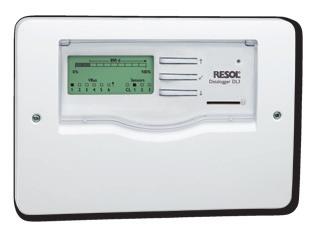


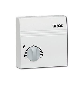
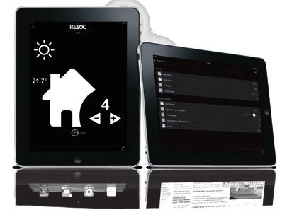

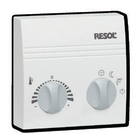


36 en 13 Accessories Sensors Kommunikationsmodul KM2 Outdoor temperature sensors AM1 Alarm Module RTA12 remote control DL2 Datalogger RCP12 Room control unit RESOL VBus / USB & VBus / LAN interface adapters 36 VBus Touch HC DL3 Datalogger
DeltaTherm HC mini * * Heating controller Manual for the specialised craftsman
 DeltaTherm HC mini Heating controller Manual for the specialised craftsman Mounting Connection Operation Troubleshooting Application examples *11205773* 11205773 Adjust your heating via app Thank you for
DeltaSol AX HE * * Differential temperature controller Manual for the specialised craftsman
 DeltaSol X HE Differtial temperature controller Manual for the specialised craftsman Installation Operation Functions and options Troubleshooting *110633* 110633 Thank you for buying this RESOL product.
DeltaSol MX. Certifi ed for the North American market! CONTROL TECHNOLOGY. incl.
 DeltaSol MX CONTROL TECHNOLOGY incl. The all-rounder HE pump control Certifi ed for the North American market! The clcus certification confirms that the controller is certified to UL 60730-2-9 and CSA
CS 2.5. Mounting and operating instructions * * Installation Operation Functions and options Troubleshooting. Manual
 Mounting and operating instructions Installation Operation Functions and options Troubleshooting *11209346* 11209346 CS 2.5 Thank you for buying this product. Read this manual carefully to get the best
DeltaSol BX * * Solar controller Manual for the specialised craftsman. Installation Operation Functions and options Troubleshooting
 DeltaSol BX from version 3.01 Solar controller Manual for the specialised craftsman Installation Operation Functions and options Troubleshooting *11209187* 11209187 The Internet portal for easy and secure
TAC 2112 Manual (GB),
,") TAC 2112 Manual T1 P1 0-004-7459-3 (GB), 1999-08-01 Contents TAC 2112 Manual Subject to modification. 1999 TAC AB Contents 1 About this manual... 1:1 1.1 Overview... 1:1 1.2 How to use this manual...
TAC 2112 Manual T1 P1 0-004-7459-3 (GB), 1999-08-01 Contents TAC 2112 Manual Subject to modification. 1999 TAC AB Contents 1 About this manual... 1:1 1.1 Overview... 1:1 1.2 How to use this manual...
Brunata Optuna H Ultrasonic energy meter Type 775 Installation Guide Edition 1.2
 Ultrasonic energy meter Type 775 Installation Guide Edition 1.2 UK-QB101575 / 29.05.2012 Brunata a/s is a Danish owned company. We have more than 90 years of experience within developing and producing
LK Wireless Room Control Cq
 LK Wireless Room Control Cq Description LK Wireless Room Control Cq consists of a LK Room Thermostat Cq-n (transmitter) and a LK Receiver Unit Cq 8 (8 channel receiver unit). The range also includes a
SOM 10. Simply the Best * * Manual for the specialized craftsman. Mounting Electrical connection Operation Troubleshooting Application examples
 SOM 10 Simply the Best Manual for the specialized craftsman Mounting Electrical connection Operation Troubleshooting Application examples *49014260* 49014260 Thank you for buying this product. Read this
SERVICE-MANUAL ROOM TEMPERATURE CONTROLLER NEA 230V / 24V. Construction Automotive Industry
 ROOM TEMPERATURE CONTROLLER NEA 230V / 24V Construction Automotive Industry ROOM TEMPERATURE CONTROLLER NEA 230V / 24V TABLE OF CONTENTS 1....... Information and safety guidelines......................................................
Control solutions Biofloor
 MR24 Central radio controller 24V Connect COMAP offers the Connect control system as part of its underfloor heating and cooling solution. Composed of a central radio control module (MR24), wireless digital
TROVIS 5500 Automation System TROVIS 5578 Heating and District Heating Controller. Mounting and Operating Instructions EB 5578 EN
 TROVIS 5500 Automation System TROVIS 5578 Heating and District Heating Controller Mounting and Operating Instructions EB 5578 EN Firmware version 2.2x Edition May 2015 Definition of signal words DANGER!
Documentation. Content. Measurement and Control. Type: ELT-GP1. 1. Installation instructions 2. Data sheets 3. Declarations of conformity
 Documentation Measurement and Control Type: ELT-GP1 Content 1. Installation instructions 2. Data sheets 3. Declarations of conformity (Part No. 008Q520) eltherm GmbH Ernst-Heinkel-Str. 6-10 57299 Burbach
S-Series Digital Thermostat
 ST320RF Manual Version 004 CMYK:Layout 1 1/9/10 09:57 Page 1 S-Series Digital Thermostat Model No ST320RF 2 Instruction Manual ST320RF Manual Version 004 CMYK:Layout 1 1/9/10 09:57 Page 2 2 ST320RF Manual
Radio Touch Order no.: 2880 xx. Operation and installation instructions. 1 Safety instructions. 2 Structure of the device (Figure 1) Radio Touch
 Radio Touch") Radio Touch Order no.: 2880 xx Operation and installation instructions 1 Safety instructions Electrical equipment must only be installed and assembled by a qualified electrician in accordance with the
Radio Touch Order no.: 2880 xx Operation and installation instructions 1 Safety instructions Electrical equipment must only be installed and assembled by a qualified electrician in accordance with the
VIESMANN. Installation and service instructions VITOTROL 300 RF. for contractors. Vitotrol 300 RF
 Installation and service instructions for contractors VIESMANN Vitotrol 3 RF Wireless remote control for one, two or three heating circuits For applicability, see the last page VITOTROL 3 RF 4/212 Please
- Wiring Brochure Universal Reset Module 423e
 - Wiring Brochure Universal Reset Module 4e W 4e 0/08 Information Brochure Choose controls to match application Application Brochure Design your mechanical applications Rough In Wiring Rough-in wiring
Instruction. INFOCAL 8 Energy calculator. 1.0 Table of contents. 2.0 Safety notes and product information
 Instruction INFOCAL 8 Energy calculator 1.0 Table of contents 1.0 Table of contents...1 2.0 Safety notes and product information...1 3.0 Installation of energy calculator...2 4.0 Installation of temperature
Thermostat P. Thermostats Electronic room thermostat with clock for thermal actuators
 Thermostat P Thermostats Electronic room thermostat with clock for thermal actuators IMI HEIMEIER / Thermostats & Actuators / Thermostat P Thermostat P The Thermostat P room temperature controller is used
TROVIS 5500 Automation System TROVIS 5578 Heating and District Heating Controller. Mounting and Operating Instructions EB 5578 EN
 TROVIS 5500 Automation System TROVIS 5578 Heating and District Heating Controller Mounting and Operating Instructions EB 5578 EN Firmware version 2.30 Edition November 2017 Definition of signal words DANGER!
ABB i-bus EIB / KNX Analogue Input AE/S 4.2
 Product Manual ABB i-bus EIB / KNX Analogue Input AE/S 4.2 Intelligent Installation Systems This manual describes the functionality of Analogue Input AE/S 4.2. Subject to changes and errors excepted. Exclusion
Installation Guide. ECL Comfort 310, application A Table of Contents
 1.0 Table of Contents 1.0 Table of Contents... 1 1.1 Important safety and product information..................... 2 2.0 Installation... 5 2.1 Before you start.....................................................
User Instructions For TopTronic RS-10
 User Instructions For TopTronic RS-0 409ENG-Dec0 Hoval Ltd Northgate Newark Nottinghamshire NG4 JN Phone 066 677 Fax 066 675 Index 409ENG-Dec0 Introduction Introduction... Controls... Display... User instructions
DeltaSol BX Plus * * Manual for the specialized craftsman. Mounting Electrical connection Operation Troubleshooting Application examples
 DeltaSol BX Plus Manual for the specialized craftsman Mounting Electrical connection Operation Troubleshooting Application examples *11210238* 11210238 Thank you for buying this product. Read this manual
Instruction. SONOMETER 1100 Ultrasonic compact energy meter. 1.0 Table of contents. 2.0 Safety notes and product information
 Instruction SONOMETER 1100 Ultrasonic compact energy meter 1.0 Table of contents 1.0 Table of contents...1 2.0 Safety notes and product information...1 3.0 Installation of energy meter...2 4.0 Installation
Installation Guide. ECL Comfort 310, application A Table of Contents
 1.0 Table of Contents 1.0 Table of Contents... 1 1.1 Important safety and product information..................... 2 2.0 Installation... 6 2.1 Before you start.....................................................
UVR 16x2 Freely programmable universal controller
 UVR 16x2 Manual version 1.05 EN Freely programmable universal controller User manual en Table of contents Manual version 1.05 Foreword... 4 User levels... 5 Functional design... 6 Operation... 7 LED indicator...
Use of the application program. Contents. instabus EIB Application program description. September S2 Room temperature controller
 Use of the application program Product family: Product type: Manufacturer: Heating, Air conditioning, Ventilation Thermostat Siemens Name: Room temperature controller IKE 250 DELTA millennium Order no.:
RAMSES 784 HF Set 1. Bedienungsanleitung Uhrenthermostat 1. Operating Instructions Clockthermostat 14. Mode d emploi Thermostat à horloge 26
 309 484 01 RAMSES 784 HF Set 1 784 9 407 784 9 417 Bedienungsanleitung Uhrenthermostat 1 Operating Instructions Clockthermostat 14 Mode d emploi Thermostat à horloge 26 Gebruiksaanwijzing Klokthermostaat
Mounting instruction and operating manual. Access Point (UK) HmIP-HAP-UK
 HmIP-HAP-UK") Mounting instruction and operating manual Access Point (UK) HmIP-HAP-UK Package contents Quantity Description 1 Homematic IP Access Point (UK) 1 Plug-in mains adapter 1 Network cable 2 Screws 2 Plugs 1
Mounting instruction and operating manual Access Point (UK) HmIP-HAP-UK Package contents Quantity Description 1 Homematic IP Access Point (UK) 1 Plug-in mains adapter 1 Network cable 2 Screws 2 Plugs 1
Please enter the identity code of your device here!
 Operating Instructions DULCOMETER D2C Part 2: Adjustment and Operation, Measured Variables ph/chlorine dioxide ProMinent D2C2-001-pH/CIO2-GB ph/clo 2 7.20 ph 0.45 ppm DULCOMETER STOP STAR T ph/clo 2 7.20
Instruction manual. art Installation manual
 Instruction manual art. 01521 Installation manual Contents GENERAL FEATURES AND FUNCTIONALITY from page 4 ETS PARAMETERS AND COMMUNICATION OBJECTS from page 6 COMMUNICATION OBJECTS GENERAL FEATURES AND
Power supply CP-E 12/10.0 Primary switch mode power supply Data sheet
 2CDC 271 024 F0008 OUTPUT L+, L+, L-, L-: terminals - output INPUT L, N, PE: terminals - input OUTPUT OK: green LED - output voltage OK OUTPUT LOW: red LED - output voltage too low OUTPUT Adjust: potentiometer
- Wiring Brochure Universal Reset Module 423
 - Wiring Brochure Universal Reset Module 423 W 423 03/09 1 Information Brochure Choose controls to match application Application Brochure Design your mechanical applications 2 3 Rough-in Wiring Rough-in
theben Fan Coil Actuator FCA 1 Fan Coil Actuator FCA 1 FCA Version: Jan-08 (Subject to change) Page 1 of 77
 Page 1 of 77") Fan Coil Actuator FCA 1 FCA 1 492 0 200 Version: Jan-08 (Subject to change) Page 1 of 77 Contents 1 Functional characteristics...4 1.1 Operation and display...5 1.2 Advantages of the FCA 1...5 1.2.1 Special
Fan Coil Actuator FCA 1 FCA 1 492 0 200 Version: Jan-08 (Subject to change) Page 1 of 77 Contents 1 Functional characteristics...4 1.1 Operation and display...5 1.2 Advantages of the FCA 1...5 1.2.1 Special
Wireless Room Thermostat Installation and Operation Y6630D1007
 Wireless Room Thermostat Installation and Operation Y6630D1007 General safety instructions Contents 1. General safety instructions... 3 1.1. Commissioning the relay module HC60NG... 3 2. Overview... 4
Weather Station for KNX
 Weather Station for KNX Installation and Adjustment Product description... 3 Technical data... 3 PCB layout...5 230 V AC version... 5 24 V DC version... 6 Installation and commissioning... 7 Location...
Power supply CP-E 48/5.0 Primary switch mode power supply Data sheet
 2CDC 271 028 F0008 OUTPUT L+, L+, L-, L-: terminals - output Features Rated output voltage 48 V DC Output voltage adjustable via front-face rotary potentiometer OUTPUT Adjust Rated output current 5 A Rated
RMO500 M I C R O O H M M E T E R
 M I C R O O H M M E T E R Reference Manual IBEKO POWER AB Sweden 2 IBEKO POWER AB Manual Version:. MV.01 IBEKO POWER AB 2003 This Reference Manual is a publication of IBEKO POWER AB, 18 125 Lidingö, Sweden.
Power supply CP-E 24/0.75
 2CDC 271 016 F0t06 a OUTPUT L+, L : terminals output b INPUT L, N, PE: terminals input c LOW: red LED output voltage too low d OK: green LED output voltage OK e OUTPUT Adjust: rotary potentiometer output
KNX PY. Global Irradiance Sensor. Installation and Adjustment
 EN KNX PY Global Irradiance Sensor Installation and Adjustment 1 Content 1. Description... 3 1.1. Scope of delivery... 3 1.2. Technical specifications... 3 2. Installation and commissioning... 4 2.1. Notes
Power supply CP-E 24/2.5
 2CDC 271 015 F0t06 a OUTPUT L+, L : terminals output b DC OK: terminal signalling output c INPUT L, N, PE: terminals input d OUTPUT OK: green LED output voltage OK e OUTPUT Adjust: potentiometer adjustment
Universal Controller
 7 863 Universal Controller POLYGYR RWF32... ISO 9001 RWF32... with casing ARG61.01 The RWF32... is a universal digital boiler temperature / pressure controller designed for use in oil- and / or gas-fired
1 SAFETY INSTALLATION OPERATION COMPONENTS FAULT DIAGNOSTICS FUNCTIONS TECHNICAL SPECIFICATIONS...
 1 SAFETY... 2 1.1 Troubleshooting... 2 1.2 The microwave oven warnings... 2 1.3 Inverter circuit warnings... 2 1.4 Leak test (leak measurement)... 3 2 INSTALLATION... 4 3 OPERATION... 4 4 COMPONENTS...
AURATON 2020 AURATON 2020 TX RX Plus
 0 I 31 EN AURATON 2020, AURATON 2020 TX RX Plus AURATON 2020 AURATON 2020 AURATON 2020 TX RX Plus Preliminary notes The manual includes the information on AURATON 2020 and AURATON 2020 TX RX Plus controllers.
TC 204 Heating Controller
 TC 204 Heating Controller ver. 1.32-01 The TC204 is a multi-purpose heating controller with built-in programs for different types of heating systems. General Data Power requirement 24 volts ac, 2 va Inputs
KNX manual High-performance switch actuators RM 4 H FIX1 RM 8 H FIX2
 KNX manual High-performance switch actuators RM 4 H FIX1 RM 8 H FIX2 4940212 4940217 2018-10-17 Contents 1 Function description 3 2 Operation 4 3 Technical data 5 4 The FIX2 RM 8 H application programme
CAMTO. Arc detecting relay. system. January Revised August D D1200
 NEW ARC DETECTING SYSTEM FROM Based on our experience with arc protection since 1962, has developed a new. The units are built into boxes that all fit on a 35 mm DIN-rail. All front plates are dimensioned
Self-learning Room Temperature Controller Receiver
 2 265 REV23RF REV-R.02/1 REV23RF/SE Self-learning Room emperature Controller Receiver Consisting of controller (with integrated radio transmitter) and receiver (switching unit with relay outputs) REV23RF
200 RTH OFF ON IN OUT ALARM RESET
 200 RTH OFF ON IN OUT ALARM RESET EN OWNER S MANU AL www.auraton.pl 2 3 Thank you for purchasing the modern temperature controller based on an advanced microprocessor. AURATON 200 RTH LCD FrostGuard function:
Data sheet. Function description. Benefits
 uminaire-integrated modules SESOTEC MB Sensor Modules 110042808 SESOTEC MB HF1 COM1 110051733 SESOTEC MB HF1 DAI 110059684 SESOTEC MB HF2 COM1 Function description With the new HF sensor modules, you,
RWD44U Controller. Installation and Commissioning Guide Document No October 5, Function. Application
 RWD44U Controller Installation and Commissioning Guide Document No. 129-408 Function RWD44U controllers are intended for HVAC and Refrigeration systems including Heat Pumps. They are suitable for 1-, 2-,
Radio System Strobe Wizard Plus Freemask
 Radio System Strobe Wizard Plus Freemask User manual Translation of the original German user manual Doc. No.: 900.0509.00 Version: 09/2017 Contents Information about this manual and about the manufacturer...
Wireless Receiver E28Q Mounting and Operating Instructions (Original operating instructions)
") EN Wireless Receiver E28Q Wireless Receiver E28Q Mounting and Operating Instructions (Original operating instructions) Always read before initial operation! 28509900_E28Q_EN_2012-05-08.doc 1 / 12 1 Data
EN Wireless Receiver E28Q Wireless Receiver E28Q Mounting and Operating Instructions (Original operating instructions) Always read before initial operation! 28509900_E28Q_EN_2012-05-08.doc 1 / 12 1 Data
TR TR 641 top TR 642 top TR 644 top TR 641 top2 RC TR 642 top2 RC TR 644 top2 RC
 2 2 309 429 01 TR TR 641 top2 641 0 100 TR 642 top2 642 0 100 TR 644 top2 644 0 100 TR 641 top2 RC 641 0 300 TR 642 top2 RC 642 0 300 TR 644 top2 RC 644 0 300 Installation and operating instructions Digital
PRODUCT CATALOGUE TEMPERATURE CONTROL Grässlin products for individual control of temperature
 PRODUCT CATALOGUE TEMPERATURE CONTROL Grässlin products for individual control of temperature Temperature control: Feel good at any time of year Room thermostats Heating time switches Excellent products
Expandable Controller 3, 7, 11, 15 stations Installation and Programming Guide
 seconds. This blinking cycle is to go on until the low battery condition is corrected. At that time the normal display returns. Also, while LO BA is blinking, if the dial is turned or any button is pressed,
OPERATING INSTRUCTIONS Digital weekly time switch
 OPERATING INSTRUCTIONS Digital weekly time switch 1 Explanation of display and control buttons One-channel timer A B Two-channel timer 1.1 Control buttons i Set time and day of the week e Manual switching
GESTRA Steam Systems LRS English. Installation & Operating Instructions Conductivity Switch LRS 1-50
 GESTRA Steam Systems LRS 1-50 EN English Installation & Operating Instructions 819223-02 Conductivity Switch LRS 1-50 Contents Important notes Page Usage for the intended purpose...4 Function...4 Safety
Wireless multizone receiver RDE-MZ6
 s 1 428 Wireless multizone receiver RDE-MZ6 for floor heating / zone heating systems Mains-powered RDE-MZ6 multizone wireless receiver (AC 230 V) DIN rail mounting 2-position control with On/Off output
Operating instructions Fail-safe delay timer AZS About this document. Content
 8 Appendix 8.1 Wiring example...4 8.2 Integral System Diagnostics (ISD)....5 9 EU Declaration of conformity Operating instructions.............pages 1 to 6 Original x.000 / 11.2017 / v.a. - 101126753-
Operating instructions Electronic level sensor LK / / 2008
 Operating instructions Electronic level sensor LK31 UK 704046 / 00 01 / 2008 Contents Safety instructions...2 Menu structure...3 Controls and indicating elements...4 Function and features...5 Functional
3000W multi Pir light controller
 3000W multi Pir light controller Cat No. MLB3000 - Black Cat No. MLW3000 - White Installation & Operating Instructions INSTALLATION & operating instructions SECTION ONE GENERAL INFORMATION The unit utilises
DIGITAL RADIO INCLUDING FM, DAB AND DAB+
 DIGITAL RADIO INCLUDING FM, DAB AND DAB+ INSTRUCTION MANUAL Safety Precautions To achieve the utmost in enjoyment and performance, and in order to become familiar with its features, please read this manual
Power supply CP-D 24/1.3
 2CDC 271 027 F0t07 a OUTPUT ++/ : terminals output Features Rated output voltage 24 V DC Output voltage adjustable via front face potentiometer OUTPUT Adjust Rated output current 1.3 A Rated output power
Wireless wall transmitter, 1-gang with inscription space, Wireless wall transmitter, 3-gang with inscription space
 Wireless wall transmitter, 1-gang with inscription space Order No. : 5331.. Wireless wall Order No. : 5333.. Operating instructions 1 Safety instructions Electrical devices may only be mounted and connected
ENCORE 300 SERIES INSTALLATION AND OPERATING INSTRUCTIONS
 ENCORE 300 SERIES INSTALLATION AND OPERATING INSTRUCTIONS Copyright 2002-2006 PRI Ltd. 9600-3004-2 Issue C Information contained within this document is subject to change without notice and does not represent
Original operating instructions Fail-safe inductive sensor GG507S / / 2013
 Original operating instructions Fail-safe inductive sensor GG507S 80005283 / 00 05 / 2013 Contents 1 Preliminary note...3 1.1 Explanation of symbols...3 2 Safety instructions...4 2.1 Safety-related requirements
BU: EPBP GPG: DIN Rail Products Devices for the permanent control of insulation on supply lines for medical locations ISOLTESTER-DIG-RZ/RS/PLUS
 INSTRUCTION MANUAL BU: EPBP GPG: DIN Rail Products Devices for the permanent control of insulation on supply lines for medical locations ISOLTESTER-DIG-RZ/RS/PLUS 1/23 More information than that reported
Electrical devices may only be mounted and connected by electrically skilled persons.
 enet Server Order No. : 5301 00 Power adapter enet Server 12 V DC Operating instructions 1 Safety instructions Electrical devices may only be mounted and connected by electrically skilled persons. Serious
WIRELESS CONTROL UNIT FOR CONTROL OF ELECTRIC HEATING DEVICES (WITHIN ONE ROOM)
") PH-BSP WIRELESS CONTROL UNIT FOR CONTROL OF ELECTRIC HEATING DEVICES (WITHIN ONE ROOM) Wireless control unit Two-way radio communication on 433.92 MHz Comfortable solution of room heating Predictive system
PH-BSP WIRELESS CONTROL UNIT FOR CONTROL OF ELECTRIC HEATING DEVICES (WITHIN ONE ROOM) Wireless control unit Two-way radio communication on 433.92 MHz Comfortable solution of room heating Predictive system
CONTROL MANUAL. Dry-Pic 09PE - 09VE
 CONTROL MANUAL Dry-Pic 09PE - 09VE Translation of the original document 003, 04.01 EN CONTENTS PAGE 1 - IMPORTANT RECOMMENDATIONS 1.1 Power supply 1. Electronic board specifications 1.3 Caution 1.4 Earth
Room Temperature Controllers. for heating and cooling systems
 3 041 RCU10 RCU10.1 Room Temperature Controllers for heating and cooling systems RCU10... Choice of two-position or modulating PI control ON / OFF or PWM outputs for heating and cooling Operating modes:
Digital Function Generator
 Digital Function Generator 13654-99 PHYWE Systeme GmbH & Co. KG Robert-Bosch-Breite 10 37079 Göttingen Germany Tel. +49 (0) 551 604-0 Fax +49 (0) 551 604-107 E-mail info@phywe.de Operating Instructions
sw rev. 55B DEVICE FOR THE PERMANENT CONTROL OF INSULATION ON THE SUPPLY LINES IN MEDICAL PRACTICE PLACES INSTALLATIONS
 INSTRUCTIONS MANUAL IM831-U v0.92 HRI-R40W sw rev. 55B DEVICE FOR THE PERMANENT CONTROL OF INSULATION ON THE SUPPLY LINES IN MEDICAL PRACTICE PLACES INSTALLATIONS INDEX: GENERAL TYPES ACESSORIES AND OPTIONS
Power supply CP-E 24/2.5
 2CDC 271 015 F0t06 a OUTPUT L+, L : terminals output b DC OK: terminal signalling output c INPUT L, N, PE: terminals input d OUTPUT OK: green LED output voltage OK e OUTPUT Adjust: potentiometer adjustment
Power supply CP-E 24/20.0
 2CDC 271 027 F0008 a OUTPUT L+, L+, L, L-: terminals output b INPUT L, N, PE: terminals input c 13-14: terminals - signalling contact d OUTPUT OK: green LED output voltage OK e OUTPUT LOW: red LED output
Please enter the identity code of your device here!
 Operating Instructions DULCOMETER D1C Part 2: Adjustment and Operation, Measured Variable Conductive Conductivity ProMinent D1C2-Leit.-001-GB Conductivity 100 µs/cm DULCOMETER STOP START Conductivity 100
Device manual Multifunction display and evaluation system FX 360. Mode/Enter
 Device manual Multifunction display and evaluation system FX 360 7390275 / 08 07 / 2009 Mode/Enter Set Safety instructions This manual is part of the unit. It contains texts and diagrams for the correct
SELEKTA SELEKTA 170 top2 D GB F I E P NL PL. Installation and Operating Manual Digital astronomic time switch. SELEKTA 170 top2
 2 309 081 03 SELEKTA SELEKTA 170 top2 170 0 100 0,5mm - L N 230-240V~ Installation and Operating Manual Digital astronomic time switch MENU SELEKTA 170 top2 D F I E P NL PL 1 2 3 SELEKTA 170 top2 Correct
NOVA series Ceiling lights with tuneable white Colour temperature 2700 to 6500 K. Detailed operating instructions
 NOVA series Ceiling lights with tuneable white Colour temperature 2700 to 6500 K Detailed operating instructions 1 EN Version Date Comment BA01079601 31.10.2016 Second edition ESYLUX GmbH An der Strusbek
Mx-D15 Intelligent Valve Actuator
 Application Small radio controlled, battery-powered actuator for room temperature control. For thermostat valve bodies for direct mounting on commercially available radiator valves for room-specific temperature
Tempus Digital Digital Astro-Timer D GB CZ BZT28A71. Installation and Operating Manual BZT28A71
 2 8mm 310366 Tempus Digital Digital Astro-Timer BZT28A71 0,5mm - 2,5mm 2 0 6 12 18 24 L N 230-240V~ 50-60Hz R 10a -30T Installation and Operating Manual MENU OK BTZ28A71 D CZ PL HR 16(10)A 250V~ 1 2 3
Room Temperature Controllers. for heating and cooling systems
 3 048 RCU15 Room Temperature Controllers for heating and cooling systems RCU15 Choice of two-position or modulating PI control ON / OFF or PWM outputs for heating and cooling Control depending on room-
NX Series Inverters. HVAC Pocket Programming Guide
 NX Series Inverters HVAC Pocket Programming Guide HVAC Pocket Programming Guide HVAC Pocket Programming Guide / Contents This guide provides a single reference document for the user of NXL HVAC (product
RAM 712 KNX room thermostat for surface-mounted and flush-mounted installation
 RAM 712 KNX room thermostat for surface-mounted and flush-mounted installation RAM 712 712 9 200 Version: Dec-10 (subject to change) Page 1 of 65 Contents 1 Functional characteristics... 4 1.1 Operation...
Contents. English User Manual Regulators
 Contents Safety warnings Page 28 Technical specifications Page 28 Description of instrument Page 31 Electrical connections Page 31 Glossary Page 32 Operation Page 37 Setting the regulation parameters Page
Level Switch NRS 2-50 NRS Original Installation Instructions English
 Level Switch NRS 2-50 NRS 2-51 EN English Original Installation Instructions 819179-03 1 Contents Important Notes Page Usage for the intended purpose...4 Function...4 Safety note...4 Directives and Standards
AEROCONNECT 1B NA C Control manual
 AEROCONNECT 1B NA 11.3 C 03-01 Control manual EN CONTENTS PAGE 1 - IMPORTANT RECOMMENDATIONS 1.1 Power supply 1. Electronic board specifications 1.3 Caution 1.4 Earth 1. Sensor connections 1.6 Communication
Temperature Controller model MFC-301/T-Dry. Version for Dry Transformers and Motors. Technical Manual. Licht
 Temperature Controller model MFC-301/T-Dry Version for Dry Transformers and Motors Technical Manual Licht Contents 1 Introduction 2 2 Operating principle 3 2.1 General principle 3 2.2 RTD operation 3 3
3000W MULTI PIR LIGHT CONTROLLER
 3000W MULTI PIR LIGHT CONTROLLER Cat No. MLB3000 Black Cat No. MLW3000 White Installation & Operating Instructions INSTALLATION & OPERATING INSTRUCTIONS E G Dusk/Dawn Time Override/Holiday Mode F H Lens
Original operating instructions Fail-safe inductive sensor GM504S / / 2010
 Original operating instructions Fail-safe inductive sensor GM504S 704070 / 01 06 / 2010 Contents 1 Preliminary note 3 1.1 Explanation of symbols 3 2 Safety instructions 4 2.1 Safety-related requirements
MICROWAVE MOISTURE SENSOR WITH WIRELESS DATA TRANSMISSION FL-WAPP
 - 1 MICROWAVE MOISTURE SENSOR WITH WIRELESS DATA TRANSMISSION FL-WAPP INDEX General Function Description P. 2 Technical Data P. 2 1. Software Installation P. 3 2. System Integration P. 3 2.1 Sensor as
INSTALLATION MANUAL. Model: Smart Analyzer Manufacturer: Smart Impulse. Power meter with consumption breakdown by use 03/12/13
 INSTALLATION MANUAL Model: Smart Analyzer Manufacturer: Smart Impulse Power meter with consumption breakdown by use 03/12/13 Table of contents Table of contents... 2 1. Introduction... 3 2. Installation
MASTECH MS5908. Circuit Analyzer
 MASTECH MS5908 Circuit Analyzer Operation Manual 2 General Instructions This circuit analyzer is a special test device designed for AC low-voltage distribution line quick fault location. With simple operation,
Synchroniser Relay SYN-7
 Synchroniser Relay SYN-7 1/19 Index 1 General Remarks...3 2 Operating Principle...3 2.1 Isolated Operation (Firmware Version V1.14 or higher)...4 2.2 Usage as a locking Relay...4 2.3 Switching onto Dead
Radio receiver E17 2-channel, 27 MHz, 40MHz, or 433 MHz, 2 relay outputs. Operating voltage: 230 V/AC or 12 V or 24 V AC/DC available.
 Fig.: 230 V version Radio receiver E17 2-channel, 27 MHz, 40MHz, or 433 MHz, 2 relay outputs. Operating voltage: 230 V/AC or 12 V or 24 V AC/DC available. Installation, connection and programming instructions
Original operating instructions Fail-safe inductive sensor GG507S
 Original operating instructions Fail-safe inductive sensor GG507S 80236827 / 00 09 / 2016 Contents 1 Preliminary note...3 1.1 Symbols used...3 1.2 Warning signs used...3 2 Safety instructions...4 2.1 Safety-related
Installation and Operating Instructions. Power IT Power Factor Controller RVC
 Installation and Operating Instructions Power IT Power Factor Controller RVC Table of contents Page 1. Read this first... 3 About this Instruction Manual... 3 Safety... 3 Electromagnetic compatibility...
Fan Coil Actuator FCA 2
 Fan Coil Actuator FCA 2 FCA 2 4920210 Updated: Feb-16 (subject to changes) Page 1 of 89 Contents 1 Function description... 4 1.1 Operation and display... 5 1.2 Advantages of the FCA 2... 6 1.2.1 Special