Le L c e t c ur u e e UMTS T S Uni n ve v r e sa s l a M ob o i b le e Te T l e ec e o c m. o Sy S s y t s em e I.
|
|
|
- Jeffrey Crawford
- 6 years ago
- Views:
Transcription
1 Lecture 12 UMTS Universal Mobile Telecom. System
2 What is UMTS? UMTS stands for Universal Mobile Telecommunication System It is a part of the ITU IMT-2000 vision of a global family of 3G mobile communication systems In 1998, at the end of the proposal submission phase, 17 proposals have been presented and accepted main differences due to existing 2G networks UMTS is the European proposal 3GPP group founded to coordinate various proposals and defining a common solution Compatibility guaranteed by multi-standard multi-mode or reconfigurable terminals
3 IMT-2000 Variants IMT-2000 includes a family of terrestrial 3G systems based on the following radio interfaces IMT-DS (Direct Spread) UMTS FDD, FOMA (standardized by 3GPP) IMT-MC (Multi Carrier) CDMA 2000, evolution of IS-95 (standardized by 3GPP) IMT-TC (Time Code) UMTS TDD and TD-SCDMA (standardized by 3GPP)
4 UMTS: Initial Goals 1. UMTS will be compatible with 2G systems 2. UMTS will use the same frequency spectrum everywhere in the world 3. UMTS will be a global system 4. UMTS will provide multimedia and internet services 5. UMTS will provide QoS guarantees
5 IMT-2000 Features Higher data rate through the Air Interface At least 144 kb/s (preferably 384 kb/s) For high mobility (speed up to 250 km/h) subscribers In a wide area coverage (rural outdoor): larger than 1 km At least 384 kb/s (preferably 512 kb/s) For limited mobility (speed up to 120 km/h) subscribers In micro and macro cellular environments (urban/suburban area): max 1 km 2 Mb/s For low mobility (speed up to 10 km/h) subscribers In local coverage areas (indoor and low range outdoor): max 500 m


6 Universal Scenario


7 UMTS Network Architecture
8 UMTS Releases (1) Release 99 Major RAN release March 2000 New radio interface WCDMA New RAN architecture New CN-AC interface Open Service architecture for services GSM-UMTS Internetworking Release 4 Minor release March 2001 UTRAN access with QoS enhancements CS domain evolution, MSC servers and MGWs, based on IP protocols IP Header Compression Location services enhancements, MMS, WAP..
9 UMTS Releases (2) Release 5 Major core network release March 2002 IP Multimedia Services Subsystems SIP signalling, registration, session initiation, IMS security architecture Usage of IETF protocols (IPv6, SIP) SIP-based service environemtn QoS for IMS WCDMA enhancements (IP transport) Release 6 IMS Part II Dec 2003 IMS Phase 2 Optimized voice communications Presence, Instant Messaging, Group Management Conferencing UMTS/VLAN inter-working
10 GSM/GPRS Network Architecture Radio access network BSS GSM/GPRS core network MS BTS BSC MSC VLR GMSC HLR PSTN, ISDN BTS PCU SGSN AuC EIR IP Backbone GGSN database Internet
11 3G Rel. 99 Network Architecture Radio access network UTRAN Core network (GSM/GPRS-based) UE Uu BS BS Iub Iub Iur RNC RNC Iu CS Iu PS MSC VLR SGSN Gn GMSC HLR AuC EIR PSTN IP Backbone GGSN database Internet
12 3G in long term (1) UMTS capabilities must be progressively increased by the addition of new technologies HSPDA (High Speed Downlink Packet Access) It is a packet-based data service in WCDMA downlink with data transmission up to 8-10 Mbps (and 20 Mbps for MIMO systems) over a 5 MHz bandwidth Release 5: specifications focus on HSDPA to provide data rates up to approximately 10 Mbps to support packet-based multimedia services MIMO Systems are the work item in release 6 specifications, which will support even higher data transmission rates up to 20 Mbps. HSDPA is evolved from and backward compatible with release 99.
13 3G in long term (2) Reconfigurable terminals UMTS terminals will have to exist in a world of multiple standards. In order to provide universal coverage, seamless roaming and non standardized services, they will be in the form of a toolbox whereby the key parameters can be selected or negotiated to mach the requirements of the local radio channel In order to adapt to different standards, terminals will enable network operators to distribute new communications software via download over the air interface (this process will be invisible to the user) Capabilities of the terminal can be modified over time through a software download over the air, at the user s request or automatically by the network


14 IMT 2000 Frequency Plan TDD more efficient for asymmetric services MSS: Mobile Satellite System
15 QoS Classes and Services Conversational: real-time services with constraints on maximum packet delay (telephony, videoconference, etc.) Streaming: information retrieving services with less strict delay constraints (e.g., audio/video) Interactive: real-time data services, with delay constraints on the RTT and reliability constraints Background: best-effort traffic (SMS, ,...) with reliability constraints + evolution towards an open plaform for further application definitions (as in the Internet case)
16 Protocol Structures (1) From the protocol structure point of view the 3G network can be divided into two strata: access stratum and non-access stratum Stratum refers to the way of grouping protocols related to one aspect of the services provided by one or several domains (3GPP specifications) The access stratum contains the protocols handling activities between UE and access network The non-access stratum contains protocols handling activities between UE and Core Network

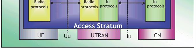
17 Protocol Structures (2)
18 With respect to GSM & GPRS UMTS defines a new Radio Access Network It adds the IMS
19 UMTS Radio Interface (UTRAN)


20 UTRAN Architecture
21 UTRAN (1) It is able to handle 2 types of calls/connections Circuit switched Packet switched The UTRAN consists of a set of Radio Network Subsystems (RNSs) connected to the CN through the Iu interface a RNS consists of a Radio Network Controller (RNC) and one or more Node Bs a Node B is connected to the RNC through the Iub interface and it can support FDD mode, TDD mode or dualmode operation RNCs of the Radio Network Subsystems can be interconnected together through the Iur interface to manage mobility inside UTRAN when MS moves from one RNS to another one (when the interface Iur is not implemented, CN is involved in HO procedures)
22 UTRAN (2) Transport technology on Iu, Iub and Iur interfaces is ATM, Asynchronous Transfer Mode Cell transmission over physical layer (SDH, PCM etc) Fast packet switching Virtual circuit/virtual path based switching Connection oriented technique
23 ATM Transmission The WCDMA Air interface provides an efficient and flexible radio access bearer for UMTS users This means that the transmission network connecting the radio access devices together must be flexible too E1, the synchronous, timeslot-based 2 Mbit/s transmission technology used by GSM could not provide the flexibility required An alternative transmission technology was chosen: ATM or Asynchronous Transfer Mode


24 GSM over E1
25 ATM transmission ATM does not base its transmission on timeslots, instead user information is carried across the network in containers called cells Each cell is a fixed length of 53 octets (bytes) and consists of a 48 octet payload that carries user data a 5 octet header that contains user identification
26 ATM transmission (2) Each user connection is allocated a unique label to identify their cells and ATM network elements are given instructions detailing where each customer s celles should be delivered If the user sends some information, it is placed in the payload of a cell and their label is added to the header; the network uses the label to determine the cell s specified delivery destination Users are not required to provide a fixed amount of data at regular intervals, as with 2 Mbit/s systems. Instead, users only fill cells when they have: bandwidth on demand
27 Circuit Switching (i) switch switch TDM link ctrl #1 #2 #8 #1 #2 #8 frame TDM slot time Time Division Multiplexing
28 Circuit Switching (ii) switch IN_A OUT_A OUT_B switch IN_A IN_B IN_B #1 #2 #8 #1 #2 #8 SWITCHING TABLE IN OUT A,1 B,2 A,3 B,4 A,4 A,2 B,1 B,1 B,4 B,3 B,6 A,1 B,7 B,5 OUT_A #1 #2 #8 OUT_B #1 #2 #8 Table setup: upon signalling
29 Statistical Multiplexing the advantage of packet switching Circuit switching: Each slot uniquely idle idle idle idle Assigned to a flow #1 #2 #3 #4 #1 #2 #3 #4 Full capacity does not imply full utilization!! Packet switching: Each packet grabs The first slot available More flows than nominal capacity may be admitted!!
30 Packet switching overhead header packet Header: contains lots of information Routing, protocol-specific info, etc Minimum: 28 bytes; in practice much more than 40 bytes Overhead for every considered protocol: (for voice: 20 bytes IP, 8 bytes UDP, 12 bytes RTP) Question: how to minimize header while maintaining packet switching? Solution: label switching (virtual circuit) ATM MPLS
31 Label Switching (virtual circuit) switch IN_A OUT_A OUT_B switch IN_A IN_B OUT_A IN_B OUT_B LABEL SWITCHING TABLE Label-IN OUT 10 A 14 B 16 B 19 B 21 B 22 B 33 A Label-OUT Condition: labels input Advantage: labels very small!! (ATM technology overhead: only 5 bytes for all info!) KEY advantage: no reserved phy slots! (asynchronous transfer mode vs synchronous)


32 ATM transmission (3)
33 UMTS Protocols Different protocol stacks for user and control plane User plane (for transport of user data): Circuit switched domain: data within bit pipes Packet switched domain: protocols for implementing various QoS or traffic engineering mechanisms Control plane (for signalling): Circuit switched domain: SS7 based (in core network) Packet switched domain: IP based (in core network) Radio access network: UTRAN protocols
34 U-Plane Protocol Stack (CS Domain) U u I u G n Data streams RLC RLC MAC MAC Frame Protocol (FP) AAL2 AAL2 ATM ATM TDM TDM Phys. WCDMA Phys. Phys. Phys. UE UTRAN 3G MSC GMSC
35 U-Plane Protocol Stack (PS Domain) IP U u I u G n IP PDCP PDCP GTP GTP GTP GTP RLC RLC UDP IP UDP IP UDP IP UDP IP MAC MAC AAL5 ATM AAL5 ATM L2 L2 Phys. WCDMA Phys. Phys. Phys. L1 L1 UE UTRAN SGSN GGSN
36 Uu interface protocols e.g. MM, CC, SM transparent to UTRAN L3 RRC PDCP L2 Signalling radio bearers RLC (User plane) radio bearers Logical channels MAC Transport channels L1 PHY
37 Main tasks of Uu interface protocols MAC (Medium Access Control) Mapping between logical and transport channels Segmentation of data into transport blocks RLC(Radio Link Control) Segmentation and reassembly Link control (flow and error control) PDCP(Packet Data Convergence Protocol IP packet header compression (user plane only);
: most popular, paired bands (1920-1980 MHz in uplink and 2110-2170 MHz in downlink) TDD+TDMA+CDMA (UTRA TDD): unpaired")
38 PHY Layer Basics 1 frequency in each cell, with 5 MHz bandwidth Reuse factor equal to 1: the same channel in all the cells, thanks to code division. Frequency division or time division duplexing FDD+CDMA (UTRA FDD): most popular, paired bands ( MHz in uplink and MHz in downlink) TDD+TDMA+CDMA (UTRA TDD): unpaired bands ( MHz and MHz)
39 Code Division Multiple Access unique code assigned to each user; i.e., code set partitioning all users share same frequency, but each user has own chipping sequence (i.e., code) to encode data encoded signal = (original data) X (chipping sequence) decoding: inner-product of encoded signal and chipping sequence allows multiple users to coexist and transmit simultaneously with minimal interference (if codes are orthogonal )
40 CDMA Encode/Decode
41 CDMA: two-sender interference
42 Spreading Factor We call "Spreading Factor" (SF) the number of chips used to code each information bit The chip rate in UMTS is fixed to 3.84 Mcps different data rates are possible according to the length of the code (i.e. according to the SF) T bit chip 8 chip code SF=8 16 chip code SF=16 Coded chip 2 bit/t 1 bit/t
43 How to create orthogonal codes? Digital/Analog Mapping logic 0 analog +1 logic 1 analog - 1
44 Orthogonal Variable Spreading Factor OVSF Code Space: 8 users; one 8-bit code per user 1 Chip Rate = Mcps kb/s 480 kb/s 480 kb/s 480 kb/s 480 kb/s 480 kb/s 480 kb/s 480 kb/s
45 OVSF Codes OVSF Code Space: 5 users; one user has 4x data bandwidth User with 4x Bit Rate 1 Chip Rate = Mcps Mb/s kb/s 480 kb/s 480 kb/s 480 kb/s = Unusable Code Space
46 Orthogonal Data Channelization Transmitter Data Channel 1 OC 1 Data Channel 2 OC 2 Receiver OC 3 Data Channel 3 OC 3 Linear Addition RF Modulation RF Demod In this example, the receiver correlates the composite received signal using Orthogonal Code 3. Data Channel 4 OC 4 The result is a perfect reconstruction of Data Channel #3, with no interference from the other data channels. To realize this perfect cross-correlation property, it is essential that the orthogonal codes be received in perfect timing relation to each other.
47 Orthogonal Codes Downlink: Orthogonal Codes used to distinguish data channels Coming from each Base Station OC1, OC2 OC3, OC4 OC5, OC6, OC7 Uplink: Orthogonal Codes used to distinguish data channels coming from each Mobile Station OC1, OC2, OC3 OC1, OC2 OC1, OC2, OC3, OC4
48 Orthogonal CDMA: Summary Code Division Multiple Access Data 1 Data 2 Data 3 CDMA allows multiple data streams to be sent on the same RF carrier Perfect isolation between data streams Timing between data streams must be exact Maximum number of data channels = orthogonal code length The longer the code, the slower the data rate... Frequency Each Data Stream has a unique Orthogonal spreading code Many users share the same frequency and time Code space can be rapidly re-allocated to match user data rate requirements CDMA advantages are limited in practice Multipath, small timing errors, and motion-related effects diminish the usable code space IS-95, cdma2000, WCDMA
49 Orthogonal codes: do they work? Case III: Correlation using Orthogonal Codes (a) Same Orthogonal code; (b) Different Orthogonal codes; (c) Same code with non-zero time offset Input Data Orthogonal code in Transmitter Transmitted Sequence x x x = = = Transmitter Orthogonal Code used in Receiver x x x = = = Receiver Integrate Result Integrate Integrate Integrate Divide by Code Length
50 Pseudo-Noise Code Properties Orthogonal codes have a limit: require perfect synchronization! Could we do something different losing a perfect orthogonality??? Yes! Pseudo Noise Codes PN Codes are repeating, defined-length blocks of 1 s and 0 s Approximately equal number of 1 s and 0 s The statistics appear randomly distributed within the block Good Autocorrelation and Cross-Correlation properties PN Code cross-correlation properties do not depend on time alignment (time offset) Example of a 32-bit (2 5 ) PN code:
51 PN Code Generation PN Codes: Generation using a Shift Register β 1 β 2 β 3 β N D D D D clock β n values are 0 or 1 (determined by the specified generator polynomial ) Maximal-length (m-sequence) has a repetitive cycle of ( 2 N - 1 ) bits A code of bits can be replicated using only a 24-bit key
52 PN Code Correlation Plots Autocorrelation of 2000-bit PN sequence Time offset = 0 Single, centered correlation peak indicates that two signals are identical, with zero time offset time offset Cross-correlation of two different PN sequences
53 Code Correlation: Key Points TX, RX use same codes, at the same time offset PN Codes: Orthogonal Codes: TX, RX use different codes PN Codes: Orthogonal Codes: 100% correlation 100% correlation Low (noise-like) correlation at any time offset Avg. correlation proportional to 1/(code length) 0% Correlation TX, RX use same codes, but at different time offsets PN Codes: Low (noise-like) correlation Orthogonal Codes: Unpredictable results
54 Spread Spectrum Multiple Access Transmitter 1 PN 1 RF Modulation Transmitter 2 PN 2 RF Modulation Receiver RF Demod PN 3 Transmitter 3 PN 3 RF Modulation In this example, the receiver correlates the composite received signal using PN code 3. Transmitter 4 PN 4 RF Modulation The result is the recovered transmission from Transmitter #3, plus some spread spectrum interference from transmitters #1, #2, and #4
55 SSMA PN Code Planning Uplink: PN Code used to distinguish each Mobile Station Downlink: PN Code used to distinguish each Base Station Cell Site 1 transmits using PN code 1 PN 1 PN 1 PN 3 PN 4 Cell Site 2 transmits using PN code 2 PN 2 PN 2 PN 5 PN 6
56 SSMA PN Code Planning N Spread Spectrum Code Planning Example W E PN7 PN2 PN3 PN2 PN1 PN7 PN3 PN2 S PN2 PN6 PN5 PN4 PN6 PN1 PN4 PN7 PN1 PN3 PN7 PN3 PN2 PN5 PN6 PN4 PN1 PN7 PN3 PN2 PN5 PN6 PN4 PN1 PN7 PN3 PN5 PN6 PN4 PN1 PN5 PN6 PN4 PN5
57 SSMA: Summary Spread Spectrum Multiple Access Tx 1 Tx 2 Tx 3... Frequency Each Transmitter has a unique PN spreading code Several Transmitters share the same frequency and time SSMA Utilization Used to distinguish the transmission source (Base Station or Mobile Station) in cellular CDMA systems Provides good (but not 100%) separation between multiple transmissions in the same geographic area, on the same frequency Works regardless of time-of-arrival delays Code Planning instead of Frequency Planning Frequency Reuse = 1 SSMA Limitations Imperfect signal separation Number of simultaneous transmitters in one area is limited by the Spreading Factor Not good for transmitting multiple data streams from one transmitter
58 Cellular CDMA (SSMA + OC) Spread Spectrum Multiple Access User 1 User 2 User 3... Code Division Multiple Access PN Spreading Codes and Frequency Orthogonal Codes Cellular CDMA (IS-95, cdma2000, WCDMA) PN Codes are used: To distinguish between Mobile Stations To distinguish between Base Stations Orthogonal Codes are used: To distinguish between data channels coming from each MS To distinguish between data channels from each BS are simultaneously utilized
59 Cellular CDMA (SSMA + OC) Voice Conversation 2 data channels (voice, control) PN1 + OC1 + OC2 Pilot, Broadcast PN1 + OC P + OC B 1 data channels (control) PN1 + OC3 Uplink Packet Data 2 data channels (voice, control) PN3 + OC1 + OC2 2 data channels (14 kbps data, control) PN4 + OC1 + OC2 Pilot, Broadcast PN2 + OC P + OC B Videoconference 3 data channels (voice, video, control) PN2 + OC1 + OC2 + OC3 4 data channels (384 kbps data, voice, video, control) PN2 + OC4 + OC5 + OC6 + OC7 Videoconference with Data 3 data channels (voice, video, control) PN5 + OC1 + OC2 + OC3 4 data channels (384 kbps data, voice, video, control) PN6 + OC1 + OC2 + OC3 + OC4
60 The Need of Power Control Pseudo-noise code work properly if interfering signals have comparable power! Let r be the sum of two interfering signals obtained from data d 1 (by user 1) and d 2 (by user 2), and pn 1 and pn 2 be the vectors containing the pseudo code used by user 1 and user 2: r = d 1 pn 1 + d 2 pn 2 Being <pn 1, pn 2 > =ε 0, receiver interested in data transmitted 1 2 by user 1 can correlate r with pn 1: < r, pn 1 >= d 1 <pn 1, pn 1 > + d2 < pn 1, pn 2 > d1+ ε But.. when the interfering signal is much higher than the useful one, the residual interference of pseudo-noise correlation can destroy the data: r = d 1 pn 1 + K d 2 pn 2 < r, pn 1 >= d 1 <pn 1, pn 1 > + K d2 < pn 1, 2 pn 2 > d1+k ε=???
61 Power Control Strategies To correct the power level on the uplink Closed loop power control Open loop power control Outer loop power control To correct the power level on the downlink Downlink power control
62 Closed Loop Power Control The antenna controller controls the UE 3-phase mechanism 1. UE transmits 2. Antenna controller measures the received power level and compares this with a threshold 3. Antenna controller tells the UE whether it has to increase or decrease its transmit power (executed periodically) Closed Loop since is a mechanism with feedback It is quite accurate, however it performs better if the initial power level is not too far from the desired value
63 Open Loop Power Control UE controls itself 2-phase mechanism 1. UE measures the interference level on the signal transmitted from the antenna controller 2. UE uses an internal algorithm to correct the power level transmitted on the uplink so that the estimated SINR is above a certain threshold Open Loop since there is not feedback It is quite inaccurate
64 Outer Loop Power Control It is a control on the control performed at the BS Outer loop power control modifies the threshold value that is employed in the closed and open loop power control Used to adapt the radio transmission to the desired level of QoS (e.g., packet error rate)
65 Downlink Power Control UE controls the antenna controller by sending a feedback (closed loop), but more slowly than the uplink feedback 3-phase mechanism: UE measures the power received from the antenna controller and asks the antenna controller for an increase or a reduction in the transmitted power The power level used by the antenna controller is derived by averaging the feedback from all users -> not a very accurate power control lower frequency (more slowly) because the communication on downlink is less critical than on uplink
66 FDD-WCDMA Parameters Multiple access scheme Channel spacing Chip rate Number of slots per frame 15 Frame length Multirate concept Modulation Detection TX - RX frequency separation WCDMA 5 MHz 3.84 Mchip/s 10 ms multicode Down-link: QPSK Up-link: Dual Code BPSK Coherent 130 MHz minimum
67 TDD-WCDMA Parameters Multiple access scheme TDMA/WCDMA Channel spacing 5 MHz Chip rate 3.84 Mchip/s Number of slots per frame 15 Frame length 10 ms Multirate concept multislot /multicode Modulation QPSK Detection Coherent, based on midamble
68 Physical, Transport, Logical Channels
69 Logical Channels Logical Channels are the services offered by the MAC layer to the RLC layer Control Channels Broadcast Control Channel (BCCH) - DL Paging Control Channel (PCCH) - DL Common Control Channel (CCCH) - DL&UL, used when there isn t a UE connection or for cell reselection Dedicated Control Channel (DCCH) - DL&UL Traffic Channel Dedicated Traffic Channel (DTCH) DL&UL Common Traffic Channel (CTCH) DL
70 Transport Channels A Transport Channel is defined by how and with which characteristics (quality level) data is transferred over the air interface Dedicated CHannels (DCH) uplink & downlink Common CHannels (CCH) uplink or downlink Shared CHannels (SCH) uplink or downlink PhyCH mapping TrCH
71 Transport Channels Packets (e.g., RLC PDU) transferred over transport channels are called Transport Blocks (TBs) Several packets can be transmitted simultaneously in Transport Block Sets (TBSs) A Transport Block or a Transport Block Set is passed to the PHY layer every Transmisson Time Interval (TTI) (TTI=k Frame, with k=1,2,..)
72 Transport Channels Types Dedicated Transport Channels Dedicated Channel (DCH) DL&UL Common Transport Channels Broadcast Channel (BCH) DL For system information Paging Channel (PCH) - DL Random Access Channel (RACH) UL For short and single packet transmissions Shared Transport Channels Common Packet Channel (CPCH) UL Shared among different users for bursty transfers Downlink Shared Channel (DSCH) DL Shared among different users for bursty & pt2pt transmissions, associated to a DCH which carries control information Forward Access Channel (FACH) DL Short & bursty transmissions
73 Transport Channel Mapping Uplink Downlink CCCH DCCH PCCH BCCH CCCH CTCH DCCH DTCH Logical channels DTCH Transport channels RACH CPCH DCH PCH BCH FACH DSCH DCH
74 Physical Channel in FDD A physical channel corresponds to: a specific carrier frequency a code (scrambling code, channelization code) on the uplink, a relative phase (0, π/2) Physical transmission is organized in Radio Frames and Slots Slots do not define phy channels, but are used for periodiic control Each Radio Frame consists of 15 slots frame x frame x chip 2560 = 667 µ s = 10 ms
75 Physical Channels in FDD DCH: Dedicated Channel Dedicated Physical Data Channel (DPDCH) Dedicated Physical Control Channel (DPCCH) PRACH: Physical Random Access Channel CPCH: Common Packet Channel Physical Common Packet Channel (PCPCH) CSMA/CD access Common Pilot Channel (CPICH) - macrodiversity BCH: Broadcast Channel Primary Common Control Physical Channel (P-CCPCH) FACH/PCH: Forward Access Channel Secondary Common Control Physical Channel (S-CCPCH) Synchronization Channel (SCH) DSCH: Downlink Shared Channel Indicators: Acquisition Indicator Channel (AICH) Access Preamble Acquisition Indicator Channel (AP-AICH) Paging Indicator Channel (PICH) CPCH Status Indicator Channel (CSICH) Collision-Detection/Channel-Assignment Indicator Channel (CN/CA-ICH)
76 Physical Channel Mapping Uplink Downlink RACH CPCH PCH FACH BCH DSCH DCH Transport channels DCH PRACH PCPCH SCCPCH PCCPCH DPDCH AICH PICH CSICH CD/CA- ICH CPICH Physical channels SCH PDSCH DPCCH DPCH
77 Uplink Physical Channels: Example Data Pilot TFCI FBI TPC Dedicated Physical Data Channel (DPDCH) Dedicated Physical Control Channel (DPCCH) Slot 0 Slot 1 Slot i Slot 14 Frame = 10 ms Pilot=known bit sequence; TFCI=Transport Format Combination ID; FBI=Feedback information; TPC=Power Control Information
78 Downlink Physical Channels: Example DPCCH DPDCH Pilot TPC TFCI Data Slot 1 Slot 2 Slot i Slot 15 Frame = 10 ms
79 Uplink Variable Rate 10 ms Rate can be varied on a per-frame basis 1-rate 1/2-rate 1/4-rate 0-rate Variable rate R = 1 R = 1/2 R = 0 R = 0 R = 1/2 : DPCCH (Pilot+TPC+TFCI+FBI) : DPDCH (Data)
80 Downlink Variable Rate Rate can be varied on a per-frame basis 1-rate ms 1/2-rate 1/4-rate 0-rate : DPCCH-part (Pilot+TPC+TFCI) : DPDCH-part (Data)

81 Downlink Shared Channel (DSCH) Within a frame, transmissions differentiated on a code basis DCH = Dedicated CHannel
82 WCDMA Air Interface Common Channels - RACH (uplink) and FACH (downlink) Random Access, No Scheduling Low Setup Time No Feedback Channel, No Fast Power Control, Use Fixed Transmission Power Poor Link-level Performance and Higher Interference Suitable for Short, Discontinuous Packet Data FACH P RACH 3 Common Channel - CPCH (uplink) P Extension for RACH Reservation across Multiple Frames Can Utilize Fast Power Control, Higher Bit Rate Suitable for Short to Medium Sized Packet Data P CPCH 1 1 P 2 2
83 WCDMA Air Interface Dedicated Channel - DCH (uplink & downlink) Dedicated, Requires Long Channel Setup Procedure Utilizes Fast Power Control Better Link Performance and Smaller Interference Suitable for Large and Continuous Blocks of Data, up to 2Mbps Variable Bitrate in a Frame-by-Frame Basis DCH (User 1) DCH (User 2) Shared Channel - DSCH (downlink) Time Division Multiplexed, Fast Allocation Utilizes Fast Power Control Better Link Performance and Smaller Interference Suitable for Large and Bursty Data, up to 2Mbps Variable Bitrate in a Frame-by-Frame Basis DSCH
84 WCDMA Air Interface Summary 5 MHz Bandwidth -> High Capacity, Multipath Diversity Variable Spreading Factor -> Bandwidth on Demand FACH RACH 3 P 3 P 1 1 CPCH P 1 1 P 2 2 DCH (User 1) DCH (User 2) DSCH
CHAPTER 2 WCDMA NETWORK
 CHAPTER 2 WCDMA NETWORK 2.1 INTRODUCTION WCDMA is a third generation mobile communication system that uses CDMA technology over a wide frequency band to provide high-speed multimedia and efficient voice
Lecture overview. UMTS concept UTRA FDD TDD
 Lecture overview 3G UMTS concept UTRA FDD TDD 3 rd Generation of Mobile Systems Goal to create a global system enabling global roaming International Mobile Telecommunications (IMT-2000) requirements: Throughput
TELE4652 Mobile and Satellite Communications
 Mobile and Satellite Communications Lecture 12 UMTS W-CDMA UMTS W-CDMA The 3G global cellular standard set to supersede GSM Universal Mobile Telecommunication System (UMTS) Slow on the uptake by mid-2008
Mobilné systémy 3. generácie UMTS
 Mobilné systémy 3. generácie UMTS Ing. Matúš Turcsány, PhD. turcsany@ktl.elf.stuba.sk KTL FEI STU 2009 Prehľad prednášok UMTS HSDPA, EUL HSPA evolution LTE LTE-Advanced Nasadené technológie GSM worldwide
Lauri Pirttiaho, NMP/Oulu
 Contents: General about radio communications systems 3GPP WCDMA L1, the physical layer structure Transmitting and receiving Channels Codings Procedures Not included: Lauri Pirttiaho, NMP/Oulu diversity
IMT IMT-2000 stands for IMT: International Mobile Communications 2000: the frequency range of 2000 MHz and the year 2000
 IMT-2000 IMT-2000 stands for IMT: International Mobile Communications 2000: the frequency range of 2000 MHz and the year 2000 In total, 17 proposals for different IMT-2000 standards were submitted by regional
RF Lecture Series Modulation Fundamentals Introduction to WCDMA
 RF Lecture Series Modulation Fundamentals Introduction to WCDMA Jeff Brenner Verigy Austin, TX 1. Introduction Second generation (2G) mobile communication standards were developed to provide higher bandwidth
Content. WCDMA BASICS HSDPA In general HSUPA
 HSPA essentials Content WCDMA BASICS HSDPA In general HSUPA WCDMA Network Architecture USIM card Affected elements for HSPA GSM/WCDMA mobile Uu GSM/WCDMA mobile WCDMA mobile Uu Uu BTS BTS RAN Iub Iub RNC
Politecnico di Milano Facoltà di Ingegneria dell Informazione MRN 9 UMTS. Mobile Radio Networks Prof. Antonio Capone
 Politecnico di Milano Facoltà di Ingegneria dell Informazione MRN 9 UMTS Mobile Radio Networks Prof. Antonio Capone 3GPP standards evolution 2G 3G 4G GSM GPRS EDGE UMTS TD-SCDMA HSDPA TDMA FDMA CDMA OFDMA
Index. API 218 APL 47 Application testing 301 Automatic Gain Control See AGC. 3GPP 18, 208, 312 3GPP specifications 47, 48, 57, 208, 220, 243, 273
 Index 3GPP 18, 208, 312 3GPP specifications 47, 48, 57, 208, 220, 243, 273 AC 21, 237, 242, 263 Acquisition Indicator 217 Active set 240, 250, 285 Adjacent power leakage See APL Admission Control See AC
References. What is UMTS? UMTS Architecture
 1 References 2 Material Related to LTE comes from 3GPP LTE: System Overview, Product Development and Test Challenges, Agilent Technologies Application Note, 2008. IEEE Communications Magazine, February
Mobile Comms. Systems. Radio Interface
 Radio Interface Multiple Access Techniques MuAT (1/23) The transmission of bidirectional information in duplex systems (uplink - UL - and downlink - DL - channels) can be done by dividing in: frequency:
Communication Networks Chapter 9: UMTS
 Communication Networks Chapter 9: UMTS o IMT-2000 o UMTS Architecture o UTRAN Architecture o UMTS Mobility Support o UMTS Development UMTS and IMT-2000 Proposals for IMT-2000 (International Mobile Telecommunications)
Cellular Network Planning and Optimization Part VI: WCDMA Basics. Jyri Hämäläinen, Communications and Networking Department, TKK, 24.1.
 Cellular Network Planning and Optimization Part VI: WCDMA Basics Jyri Hämäläinen, Communications and Networking Department, TKK, 24.1.2008 Outline Network elements Physical layer Radio resource management
UMTS: Universal Mobile Telecommunications System
 Department of Computer Science Institute for System Architecture, Chair for Computer Networks UMTS: Universal Mobile Telecommunications System Mobile Communication and Mobile Computing Prof. Dr. Alexander
WCDMA FDD Mode Transmitter. Dr. Chih-Peng Li ( 李 )
") WCDMA FDD Mode Transmitter Dr. Chih-Peng Li ( 李 ) Table of Contents Traditional Sequential ASIC Design Flow Introduction to WCDMA Transmitter Specifications WCDMA Network Architecture Physical Layer General
WCDMA FDD Mode Transmitter Dr. Chih-Peng Li ( 李 ) Table of Contents Traditional Sequential ASIC Design Flow Introduction to WCDMA Transmitter Specifications WCDMA Network Architecture Physical Layer General
David Tipper. Graduate Telecommunications and Networking Program University of Pittsburgh
 3G: UMTS overview David Tipper Associate Professor Graduate Telecommunications and Networking Program University of Pittsburgh 2700 Slides 12 Subscriber base continues to grow 1 billion wireless subscribers
Background: Cellular network technology
 Background: Cellular network technology Overview 1G: Analog voice (no global standard ) 2G: Digital voice (again GSM vs. CDMA) 3G: Digital voice and data Again... UMTS (WCDMA) vs. CDMA2000 (both CDMA-based)
WCDMA and cdma The Radio Interfaces for Future Mobile Multimedia Communications - Part II
 WCDMA and cdma2000 - The Radio Interfaces for Future Mobile Multimedia Communications - Part II Emre A. Yavuz 6.0 WCDMA The WCDMA scheme has been developed as a joint effort between ETSI and ARIB during
Mobile Communications II Chapter 5: UMTS
 Mobile Communications II Chapter 5: UMTS Universal Mobile Communication System Overview/Standardisations Architecture Data services HSPA (High Speed Packet Access) UMTS Goal to create an Universal Personal
HSPA & HSPA+ Introduction
 HSPA & HSPA+ Introduction www.huawei.com Objectives Upon completion of this course, you will be able to: Understand the basic principle and features of HSPA and HSPA+ Page1 Contents 1. HSPA & HSPA+ Overview
1. Introduction to WCDMA. 1.1 Summary of the Main Parameters in WCDMA 1.2 Power Control 1.3 Softer and Soft Handovers
 UMTS WCDMA / HSPA 1. Introduction to WCDMA 1.1 Summary of the Main Parameters in WCDMA 1.2 Power Control 1.3 Softer and Soft Handovers IMT-2000 International Mobile Telecommunications 3G Frequency Allocation
17 Third generation mobile communication systems
 17 Third generation mobile communication systems 17.1 INTRODUCTION In the previous chapters we presented examples of existing mobile communication systems. Among the second generation systems there are
ETSI TS V6.2.0 ( )
") TS 25 2 V6.2. (24-9) Technical Specification Universal Mobile Telecommunications System (UMTS); Physical channels and mapping of transport channels onto physical channels (FDD) (3GPP TS 25.2 version 6.2.
TS 25 2 V6.2. (24-9) Technical Specification Universal Mobile Telecommunications System (UMTS); Physical channels and mapping of transport channels onto physical channels (FDD) (3GPP TS 25.2 version 6.2.
Chapter 8: GSM & CDAMA Systems
 Chapter 8: GSM & CDAMA Systems Global System for Mobile Communication (GSM) Second Generation (Digital) Cellular System Operated in 900 MHz band GSM is also operated in 1800 MHz band and this version of
CDMA & WCDMA (UMTS) AIR INTERFACE. ECE 2526-WIRELESS & CELLULAR COMMUNICATION SYSTEMS Monday, June 25, 2018
 AIR INTERFACE. ECE 2526-WIRELESS & CELLULAR COMMUNICATION SYSTEMS Monday, June 25, 2018") CDMA & WCDMA (UMTS) AIR INTERFACE ECE 2526-WIRELESS & CELLULAR COMMUNICATION SYSTEMS Monday, June 25, 2018 SPREAD SPECTRUM OPTIONS (1) Fast Frequency Hopping (FFSH) Advantages: Has higher anti-jamming
CDMA & WCDMA (UMTS) AIR INTERFACE ECE 2526-WIRELESS & CELLULAR COMMUNICATION SYSTEMS Monday, June 25, 2018 SPREAD SPECTRUM OPTIONS (1) Fast Frequency Hopping (FFSH) Advantages: Has higher anti-jamming
Macro Diversity Combining Optimisation in HSPA Flat Architecture
 HELSINKI UNIVERSITY OF TECHNOLOGY Faculty of Electronics, Communication and Automation Department of Communications and Networking Macro Diversity Combining Optimisation in HSPA Flat Architecture Petri
UMR UTC/CNRS Cellular Networks
 UMR UTC/CNRS 7253 www.hds.utc.fr Cellular Networks Enrico NATALIZIO enrico.natalizio@hds.utc.fr 1 Cellular networks - history Radio communication was invented by Nikola Tesla and Guglielmo Marconi: in
University of Twente. Faculty of Electrical Engineering, Mathematics and Computer Science (EEMCS) WCDMA Enhanced Uplink performance evaluation
 WCDMA Enhanced Uplink performance evaluation") University of Twente Faculty of Electrical Engineering, Mathematics and Computer Science (EEMCS) WCDMA Enhanced Uplink performance evaluation Camilo Orejuela Mesa Master of Science in Telematics Thesis
University of Twente Faculty of Electrical Engineering, Mathematics and Computer Science (EEMCS) WCDMA Enhanced Uplink performance evaluation Camilo Orejuela Mesa Master of Science in Telematics Thesis
Mobile Network Evolution Part 1. GSM and UMTS
 Mobile Network Evolution Part 1 GSM and UMTS GSM Cell layout Architecture Call setup Mobility management Security GPRS Architecture Protocols QoS EDGE UMTS Architecture Integrated Communication Systems
Developing Mobile Applications
 Developing Mobile Applications GSM networks 1 carriers GSM 900 MHz 890-915 MHz 935-960 MHz up down 200 KHz 200 KHz 25 MHz 25 MHz 2 frequency reuse A D K B J L C H E G I F A 3 Reuse patterns 4/12 4 base
Agilent Designing and Testing 3GPP W-CDMA Base Transceiver Stations
 Agilent Designing and Testing 3GPP W-CDMA Base Transceiver Stations Application Note 1355 DTCH data bits DCCH data bits Add CRC & tail bits Add CRC & tail bits Conv. coder Conv. coder Rate matching Rate
LTE systems: overview
 LTE systems: overview Luca Reggiani LTE overview 1 Outline 1. Standard status 2. Signal structure 3. Signal generation 4. Physical layer procedures 5. System architecture 6. References LTE overview 2 Standard
A NEW EFFICIENT HANDOVER ALGORITHM FOR MBMS ENABLED 3G MOBILE CELLULAR NETWORKS UNIVERSITY OF CYPRUS
 Master s Thesis A NEW EFFICIENT HANDOVER ALGORITHM FOR MBMS ENABLED 3G MOBILE CELLULAR NETWORKS Christopher Christophorou UNIVERSITY OF CYPRUS DEPARTMENT OF COMPUTER SCIENCE December 2005 UNIVERSITY OF
RADIO LINK ASPECT OF GSM
 RADIO LINK ASPECT OF GSM The GSM spectral allocation is 25 MHz for base transmission (935 960 MHz) and 25 MHz for mobile transmission With each 200 KHz bandwidth, total number of channel provided is 125
DOWNLINK AIR-INTERFACE...
 1 ABBREVIATIONS... 10 2 FUNDAMENTALS... 14 2.1 INTRODUCTION... 15 2.2 ARCHITECTURE... 16 2.3 INTERFACES... 18 2.4 CHANNEL BANDWIDTHS... 21 2.5 FREQUENCY AND TIME DIVISION DUPLEXING... 22 2.6 OPERATING
High-Speed Downlink Packet Access (HSDPA)
") High-Speed Downlink Packet Access (HSDPA) HSDPA Background & Basics Principles: Adaptive Modulation, Coding, HARQ Channels/ UTRAN Architecture Resource Management: Fast Scheduling, Mobility Performance
High-Speed Downlink Packet Access (HSDPA) HSDPA Background & Basics Principles: Adaptive Modulation, Coding, HARQ Channels/ UTRAN Architecture Resource Management: Fast Scheduling, Mobility Performance
Part 7. B3G and 4G Systems
 Part 7. B3G and 4G Systems p. 1 Roadmap HSDPA HSUPA HSPA+ LTE AIE IMT-Advanced (4G) p. 2 HSPA Standardization 3GPP Rel'99: does not manage the radio spectrum efficiently when dealing with bursty traffic
Enhanced Uplink Dedicated Channel (EDCH) High Speed Uplink Packet Access (HSUPA)
 High Speed Uplink Packet Access (HSUPA)") Enhanced Uplink Dedicated Channel (EDCH) High Speed Uplink Packet Access (HSUPA) EDCH Background & Basics Channels/ UTRAN Architecture Resource Management: Scheduling, Handover Performance Results Background
Enhanced Uplink Dedicated Channel (EDCH) High Speed Uplink Packet Access (HSUPA) EDCH Background & Basics Channels/ UTRAN Architecture Resource Management: Scheduling, Handover Performance Results Background
Enhanced High-Speed Packet Access HSPA+ Background: HSPA Evolution Higher Data Rates Signaling Improvements Architecture Evolution/ Home NodeB
 Enhanced High-Speed Packet Access HSPA+ Background: HSPA Evolution Higher Data Rates Signaling Improvements Architecture Evolution/ Home NodeB HSPA+ (HSPA Evolution) Background For operators deploying
Enhanced High-Speed Packet Access HSPA+ Background: HSPA Evolution Higher Data Rates Signaling Improvements Architecture Evolution/ Home NodeB
 Enhanced High-Speed Packet Access HSPA+ Background: HSPA Evolution Higher Data Rates Signaling Improvements Architecture Evolution/ Home NodeB HSPA+ The evolution of UMTS HSPA Corresponding to UMTS Release
A Simulation Tool for Third Generation CDMA Systems Presentation to IEEE Sarnoff Symposium
 A Simulation Tool for Third Generation CDMA Systems Presentation to IEEE Sarnoff Symposium March 22, 2000 Fakhrul Alam, William Tranter, Brian Woerner Mobile and Portable Radio Research Group () e-mail:
IS-95 /CdmaOne Standard. By Mrs.M.R.Kuveskar.
 IS-95 /CdmaOne Standard By Mrs.M.R.Kuveskar. CDMA Classification of CDMA Systems CDMA SYSTEMS CDMA one CDMA 2000 IS95 IS95B JSTD 008 Narrow Band Wide Band CDMA Multiple Access in CDMA: Each user is assigned
IMT-2000/UMTS delivering full BWA
 IMT-2000/UMTS delivering full BWA Rémi THOMAS Directeur du projet réseau UMTS d Orange France Agenda 3G and IMT 2000 Family UMTS phase 1 principles From GSM to GSM/UMTS Key Technical Characteristics of
3G Technologies. Outline. WCDMA, TD-(S)CDMA and cdma2000 Janne Kurjenniemi. Background. 3G technologies WCDMA TD-(S)CDMA. cdma2000
CDMA and cdma2000 Janne Kurjenniemi. Background. 3G technologies WCDMA TD-(S)CDMA. cdma2000") 3G Technologies WCDMA, TD-(S)CDMA and cdma2000 Janne Kurjenniemi 1 Magister Solutions 2006-11-02 / JKu Outline Background Why new radio access Frequency allocation Spread spectrum 3G technologies WCDMA
3G Technologies WCDMA, TD-(S)CDMA and cdma2000 Janne Kurjenniemi 1 Magister Solutions 2006-11-02 / JKu Outline Background Why new radio access Frequency allocation Spread spectrum 3G technologies WCDMA
Keysight Technologies Designing and Testing 3GPP W-CDMA Base Transceiver Stations (Including Femtocells)
") Keysight Technologies Designing and Testing 3GPP W-CDMA Base Transceiver Stations (Including Femtocells) Application Note DTCH data bits DCCH data bits Add CRC & tail bits Add CRC & tail bits Conv. coder
Keysight Technologies Designing and Testing 3GPP W-CDMA Base Transceiver Stations (Including Femtocells) Application Note DTCH data bits DCCH data bits Add CRC & tail bits Add CRC & tail bits Conv. coder
ICT 5305 Mobile Communications. Lecture - 6 April Dr. Hossen Asiful Mustafa
 ICT 5305 Mobile Communications Lecture - 6 April 2016 Dr. Hossen Asiful Mustafa 4 types of handover 1 2 3 4 MS MS MS MS BTS BTS BTS BTS BSC BSC BSC MSC MSC Handover decision receive level BTS old receive
David Tipper. Graduate Telecommunications and Networking Program University of Pittsburgh
 3G: UMTS overview David Tipper Associate Professor Graduate Telecommunications and Networking Program University of Pittsburgh 2700 Slides 8 Subscriber base continues to grow 1 billion wireless subscribers
ETSI TS V2.1.1 ( ) Technical Specification
 Technical Specification") TS 85--2 V2.. (28-) Technical Specification Satellite Earth Stations and Systems (SES); Satellite Component of UMTS/IMT-2; Part : Physical channels and mapping of transport channels into physical channels;
TS 85--2 V2.. (28-) Technical Specification Satellite Earth Stations and Systems (SES); Satellite Component of UMTS/IMT-2; Part : Physical channels and mapping of transport channels into physical channels;
CHAPTER 13 CELLULAR WIRELESS NETWORKS
 CHAPTER 13 CELLULAR WIRELESS NETWORKS These slides are made available to faculty in PowerPoint form. Slides can be freely added, modified, and deleted to suit student needs. They represent substantial
UMTS Radio Access Network Physical Layer. Fabrizio Tomatis
 UMTS Radio Access Network Physical Layer Fabrizio Tomatis Agenda 3G Standardization process 3GPP standardization committee ITU and frequency planning Physical layer principles Mapping of transport channels
An Introduction to Wireless Technologies Part 2. F. Ricci
 An Introduction to Wireless Technologies Part 2 F. Ricci Content Medium access control (MAC): FDMA = Frequency Division Multiple Access TDMA = Time Division Multiple Access CDMA = Code Division Multiple
LTE Aida Botonjić. Aida Botonjić Tieto 1
 LTE Aida Botonjić Aida Botonjić Tieto 1 Why LTE? Applications: Interactive gaming DVD quality video Data download/upload Targets: High data rates at high speed Low latency Packet optimized radio access
RFCD 202: Introduction to W-CDMA
 RFCD 202: Introduction to W-CDMA Technical data is subject to change Copyright@2003 Agilent Technologies Printed on Dec. 4, 2002 5988-8504ENA This paper examines the core concepts of one operating mode
3GPP: Evolution of Air Interface and IP Network for IMT-Advanced. Francois COURAU TSG RAN Chairman Alcatel-Lucent
 3GPP: Evolution of Air Interface and IP Network for IMT-Advanced Francois COURAU TSG RAN Chairman Alcatel-Lucent 1 Introduction Reminder of LTE SAE Requirement Key architecture of SAE and its impact Key
ETSI SMG#24 TDoc SMG2 898 / 97 Madrid, Spain December 15-19, 1997 Source: SMG2. Concept Group Delta WB-TDMA/CDMA: Evaluation Summary
 ETSI SMG#24 TDoc SMG2 898 / 97 Madrid, Spain December 15-19, 1997 Source: SMG2 Concept Group Delta WB-TDMA/CDMA: Evaluation Summary Introduction In the procedure to define the UMTS Terrestrial Radio Access
MOBILE COMPUTING 4/8/18. Basic Call. Public Switched Telephone Network - PSTN. CSE 40814/60814 Spring Transit. switch. Transit. Transit.
 MOBILE COMPUTING CSE 40814/60814 Spring 2018 Public Switched Telephone Network - PSTN Transit switch Transit switch Long distance network Transit switch Local switch Outgoing call Incoming call Local switch
CS 6956 Wireless & Mobile Networks April 1 st 2015
 CS 6956 Wireless & Mobile Networks April 1 st 2015 The SIM Card Certain phones contain SIM lock and thus work only with the SIM card of a certain operator. However, this is not a GSM restriction introduced
ETSI TS V1.2.1 ( )
") TS 85- V.2. (26-) Technical Specification Satellite Earth Stations and Systems (SES); Satellite Component of UMTS/IMT2; G-family; Part : Physical channels and mapping of transport channels into physical
TS 85- V.2. (26-) Technical Specification Satellite Earth Stations and Systems (SES); Satellite Component of UMTS/IMT2; G-family; Part : Physical channels and mapping of transport channels into physical
ETSI SMG#24 TDoc SMG 903 / 97. December 15-19, 1997 Source: SMG2. Concept Group Alpha - Wideband Direct-Sequence CDMA: System Description Summary
 ETSI SMG#24 TDoc SMG 903 / 97 Madrid, Spain Agenda item 4.1: UTRA December 15-19, 1997 Source: SMG2 Concept Group Alpha - Wideband Direct-Sequence CDMA: System Description Summary Concept Group Alpha -
Designing and Testing 3GPP W-CDMA Base Stations
 Agilent Designing and Testing 3GPP W-CDMA Base Stations Application Note 1355 DTCH data bits DCCH data bits Add CRC & tail bits Add CRC & tail bits Conv. coder Conv. coder Rate matching Rate matching Interleaver
Multi-User Communication
 Multi-User Communication Lecture 10 WCDMA Overview slide 1 Objective Introduce WCDMA from a systems perspective, but with a focus on lower layers (FDD mode) WCDMA Release 99 giving you, hopefully a technology
Wireless Medium Access Control and CDMA-based Communication Lesson 14 CDMA2000
 Wireless Medium Access Control and CDMA-based Communication Lesson 14 CDMA2000 1 CDMA2000 400 MHz, 800 MHz, 900 MHz, 1700 MHz, 1800 MHz, 1900 MHz, and 2100 MHz Compatible with the cdmaone standard A set
WCDMA System Overview
 Wireless Information Transmission System Lab. WCDMA System Overview Institute of Communications Engineering National Sun Yat-sen University Table of Contents Background and Standardization of WCDMA WCDMA
IMT-2000 members UTRA-TDD and UTRA-FDD
 IMT-2000 members UTRA-TDD and UTRA-FDD Dr. Christian Menzel, SIEMENS AG christian.menzel@icn.siemens.de Author Siemens AG, Munich Siemens AG 2000 IMT-2000_UTRA_TDD_FDD_1 UTRA (FDD + TDD)! IMT-2000 and
Voice over IP Realized for the 3GPP Long Term Evolution
 Voice over IP Realized for the 3GPP Long Term Evolution Fredrik Persson Ericsson Research Ericsson AB, SE-164 80 Stockholm, Sweden fredrik.f.persson@ericsson.com Abstract The paper outlines voice over
Introduction. Air Interface. LTE and UMTS Terminology and Concepts
 LTE and UMTS Terminology and Concepts By Chris Reece, Subject Matter Expert - 8/2009 UMTS and LTE networks are surprisingly similar in many respects, but the terms, labels and acronyms they use are very
HSDPA RF Measurements with the R&S CMW500 in line with 3GPP TS Application Note. Products: R&S CMW500
 HSDPA RF Measurements with the R&S CMW500 in line with 3GPP TS 34.121 Application Note Products: R&S CMW500 Most of the tests specified in the TS 34.121 standard [1] for 3GPP Release-5 (Rel-5) can be performed
ETSI TS V ( )
") TS 125 302 V3.11.0 (2001-12) Technical Specification Universal Mobile Telecommunications System (UMTS); Services provided by the physical layer (3GPP TS 25.302 version 3.11.0 Release 1999) 1 TS 125 302
TS 125 302 V3.11.0 (2001-12) Technical Specification Universal Mobile Telecommunications System (UMTS); Services provided by the physical layer (3GPP TS 25.302 version 3.11.0 Release 1999) 1 TS 125 302
Contents. UMTS Radio Access Network (UTRAN) UTRAN Architecture. Refresher: Some concepts. UTRAN Bearer Architecture.
 UTRAN Architecture. Refresher: Some concepts. UTRAN Bearer Architecture.") Contents UMTS Radio Access Network (UTRAN) T-110.498 UMTS Networks Chapter 4 Päivi Savola 4.2.2003 UTRAN Architecture Base Station Radio Network Controller Radio Resource Management, QoS Control Functions
Contents UMTS Radio Access Network (UTRAN) T-110.498 UMTS Networks Chapter 4 Päivi Savola 4.2.2003 UTRAN Architecture Base Station Radio Network Controller Radio Resource Management, QoS Control Functions
ETSI TR V1.1.1 ( )
") TR 102 058 V1.1.1 (2004-11) Technical Report Satellite Earth Stations and Systems (SES); Satellite Component of UMTS/IMT-2000; Evaluation of the W-CDMA UTRA FDD as a Satellite Radio Interface 2 TR 102
TR 102 058 V1.1.1 (2004-11) Technical Report Satellite Earth Stations and Systems (SES); Satellite Component of UMTS/IMT-2000; Evaluation of the W-CDMA UTRA FDD as a Satellite Radio Interface 2 TR 102
Technical Aspects of LTE Part I: OFDM
 Technical Aspects of LTE Part I: OFDM By Mohammad Movahhedian, Ph.D., MIET, MIEEE m.movahhedian@mci.ir ITU regional workshop on Long-Term Evolution 9-11 Dec. 2013 Outline Motivation for LTE LTE Network
EDCH Background & Basics. Principles: scheduling, handover Performance Results
 Enhanced Uplink Dedicated Channel (EDCH) High Speed Uplink Packet Access (HSUPA) EDCH Background & Basics Channels/ UTRAN Architecture Principles: scheduling, handover Performance Results Background E-DCH
HSDPA SYSTEM SIMULATION
 Thesis Number: MEE05:30 HSDPA SYSTEM SIMULATION Nguyen Kim Cuong Khan Muhammad Sohaib This thesis is presented as part of Degree of Master of Science in Electrical Engineering Blekinge Institute of Technology
Chapter 5 3G Wireless Systems. Mrs.M.R.Kuveskar.
 Chapter 5 3G Wireless Systems Mrs.M.R.Kuveskar. Upgrade paths for 2G Technologies 2G IS-95 GSM- IS-136 & PDC 2.5G IS-95B HSCSD GPRS EDGE Cdma2000-1xRTT W-CDMA 3G Cdma2000-1xEV,DV,DO EDGE Cdma2000-3xRTT
Long Term Evolution (LTE)
") 1 Lecture 13 LTE 2 Long Term Evolution (LTE) Material Related to LTE comes from 3GPP LTE: System Overview, Product Development and Test Challenges, Agilent Technologies Application Note, 2008. IEEE Communications
1 Lecture 13 LTE 2 Long Term Evolution (LTE) Material Related to LTE comes from 3GPP LTE: System Overview, Product Development and Test Challenges, Agilent Technologies Application Note, 2008. IEEE Communications
<Technical Report> Number of pages: 20. XGP Forum Document TWG TR
 XGP Forum Document TWG-009-01-TR Title: Conformance test for XGP Global Mode Version: 01 Date: September 2, 2013 XGP Forum Classification: Unrestricted List of contents: Chapter 1 Introduction
Introductions to WCDMA FDD Mode Physical Layer
 Wireless Information Transmission System Lab. Introductions to WCDMA FDD Mode Physical Layer Institute of Communications Engineering National Sun Yat-sen University Table of Contents Traditional Sequential
<3rd generation CDMA wireless systems>
 Page 1 Overview What is 3G? A brief overview of IS95 Key design choices for CDMA 3G systems. Bandwidth Modulation Coding Power Control
Vocoder RNS RNC. Node B. Node B UE2. Figure 1. Synchronisation issues model.
 TSG-RAN Working Group 2 (Radio layer 2 and Radio layer 3) TSGR2#2(99) 90 Stockholm 8 th to 11 th March 1999 Agenda Item: 8.7 Source: Title: Nokia UTRAN Synchronisation Document for: FYI [This contribution
ETSI TS V ( )
") TS 125 306 V5.10.0 (2005-03) Technical Specification Universal Mobile Telecommunications System (UMTS); UE Radio Access capabilities definition (3GPP TS 25.306 version 5.10.0 Release 5) 1 TS 125 306 V5.10.0
TS 125 306 V5.10.0 (2005-03) Technical Specification Universal Mobile Telecommunications System (UMTS); UE Radio Access capabilities definition (3GPP TS 25.306 version 5.10.0 Release 5) 1 TS 125 306 V5.10.0
Introduction to WCDMA and WCDMA Dimensioning for UMTS
 Introduction to WCDMA and WCDMA Dimensioning for UMTS 1 internet Third generation services 2M 384K video conference video conference remote medical service video catalogue shopping video on demand mobile
Channelisation Codes (2)
") Channelisation Codes (2) Scram. #0 +Chan. #1 Scram. #0 +Chan. #0 Scram. #1 +Chan. #0 R.Scram. #1 +Chan. #0 R.Scram. #1 +Chan. #1 R.Scram. #0 +Chan. #0 R.Scram. #0 +Chan. #1 p. 51 Channelisation Codes (3)
Channelisation Codes (2) Scram. #0 +Chan. #1 Scram. #0 +Chan. #0 Scram. #1 +Chan. #0 R.Scram. #1 +Chan. #0 R.Scram. #1 +Chan. #1 R.Scram. #0 +Chan. #0 R.Scram. #0 +Chan. #1 p. 51 Channelisation Codes (3)
RADIO SYSTEMS ETIN15. Lecture no: GSM and WCDMA. Ove Edfors, Department of Electrical and Information Technology
 RADIO SYSTEMS ETIN15 Lecture no: 11 GSM and WCDMA Ove Edfors, Department of Electrical and Information Technology Ove.Edfors@eit.lth.se 1 Contents (Brief) history of mobile telephony Global System for
Wireless CommuniCation. unit 5
 Wireless CommuniCation unit 5 V. ADVANCED TRANSCEIVER SCHEMES Spread Spectrum Systems- Cellular Code Division Multiple Access Systems- Principle, Power control, Effects of multipath propagation on Code
GSM and WCDMA RADIO SYSTEMS ETIN15. Lecture no: Ove Edfors, Department of Electrical and Information Technology
 RADIO SYSTEMS ETIN15 Lecture no: 11 GSM and WCDMA Ove Edfors, Department of Electrical and Information Technology Ove.Edfors@eit.lth.se 2015-05-12 Ove Edfors - ETIN15 1 Contents (Brief) history of mobile
Current Situation and Development Trend of Mobile Communication Systems
 Journal of Secure Communication and System (2017) Original Research Article Current Situation and Development Trend of Mobile Communication Systems Jun Lin,Siyang Zhao,Weihua Yi,Zhidong Yu School of Communication
W-CDMA for UMTS Principles
 W-CDMA for UMTS Principles Introduction CDMA Background/ History Code Division Multiple Access (CDMA) Why CDMA? CDMA Principles / Spreading Codes Multi-path Radio Channel and Rake Receiver Problems to
ETSI TR V1.1.1 ( )
") TR 101 866 V1.1.1 (2001-07) Technical Report Satellite Earth Stations and Systems (SES); Satellite Component of UMTS/IMT-2000; Analysis and definition of the Packet Mode 2 TR 101 866 V1.1.1 (2001-07) Reference
TR 101 866 V1.1.1 (2001-07) Technical Report Satellite Earth Stations and Systems (SES); Satellite Component of UMTS/IMT-2000; Analysis and definition of the Packet Mode 2 TR 101 866 V1.1.1 (2001-07) Reference
MNA Mobile Radio Networks Mobile Network Architectures
 MNA Mobile Radio Networks Mobile Network Architectures Roberto Verdone roberto.verdone@unibo.it +39 051 20 93817 Office Hours: Monday 4 6 pm (upon prior agreement via email) Slides are provided as supporting
ETSI TS V8.5.0 ( ) Technical Specification
 Technical Specification") TS 125 221 V.5.0 (2009-06) Technical Specification Universal Mobile Telecommunications System (UMTS); Physical channels and mapping of transport channels onto physical channels (TDD) (3GPP TS 25.221 version.5.0
TS 125 221 V.5.0 (2009-06) Technical Specification Universal Mobile Telecommunications System (UMTS); Physical channels and mapping of transport channels onto physical channels (TDD) (3GPP TS 25.221 version.5.0
LTE (Long Term Evolution)
") LTE (Long Term Evolution) Assoc. Prof. Peter H J Chong, PhD (UBC) School of EEE Nanyang Technological University Office: +65 6790 4437 E-mail: ehjchong@ntu.edu.sg 2 Outline Introduction SAE (System Architecture
LTE (Long Term Evolution) Assoc. Prof. Peter H J Chong, PhD (UBC) School of EEE Nanyang Technological University Office: +65 6790 4437 E-mail: ehjchong@ntu.edu.sg 2 Outline Introduction SAE (System Architecture
Concept Group Alpha - Wideband Direct-Sequence CDMA (WCDMA) EVALUATION DOCUMENT (3.0) Part 1: System Description Performance Evaluation
 EVALUATION DOCUMENT (3.0) Part 1: System Description Performance Evaluation") ETSI SMG Tdoc SMG 905/97 Meeting no 24 Madrid, Spain 15-19 December 1997 Source: SMG2 Concept Group Alpha - Wideband Direct-Sequence CDMA (WCDMA) EVALUATION DOCUMENT (3.0) Part 1: System Description Performance
ETSI SMG Tdoc SMG 905/97 Meeting no 24 Madrid, Spain 15-19 December 1997 Source: SMG2 Concept Group Alpha - Wideband Direct-Sequence CDMA (WCDMA) EVALUATION DOCUMENT (3.0) Part 1: System Description Performance
LTE Air Interface. Course Description. CPD Learning Credits. Level: 3 (Advanced) days. Very informative, instructor was engaging and knowledgeable!
 days. Very informative, instructor was engaging and knowledgeable!") Innovating Telecoms Training Very informative, instructor was engaging and knowledgeable! Watch our course intro video. LTE Air Interface Course Description With the introduction of LTE came the development
Innovating Telecoms Training Very informative, instructor was engaging and knowledgeable! Watch our course intro video. LTE Air Interface Course Description With the introduction of LTE came the development
Technology Introduction. White Paper
 HSPA+ Technology Introduction Meik Kottkamp 0.202-MA-205_2E HSPA+ Technology Introduction White Paper High Speed Downlink Packet Access (HSDPA) and High Speed Uplink Packet Access (HSUPA) optimize UMTS
CS 218 Fall 2003 October 23, 2003
 CS 218 Fall 2003 October 23, 2003 Cellular Wireless Networks AMPS (Analog) D-AMPS (TDMA) GSM CDMA Reference: Tanenbaum Chpt 2 (pg 153-169) Cellular Wireless Network Evolution First Generation: Analog AMPS:
ETSI TS V7.2.0 ( )
") TS 125 308 V7.2.0 (2007-03) Technical Specification Universal Mobile Telecommunications System (UMTS); High Speed Downlink Packet Access (HSDPA); Overall description; Stage 2 (3GPP TS 25.308 version 7.2.0
TS 125 308 V7.2.0 (2007-03) Technical Specification Universal Mobile Telecommunications System (UMTS); High Speed Downlink Packet Access (HSDPA); Overall description; Stage 2 (3GPP TS 25.308 version 7.2.0
UMTS Terrestrial Radio Access Network (UTRAN)
") UMTS Terrestrial Radio Access Network (UTRAN) UTRAN Architecture and Protocols UMTS Terrestrial Radio Access (UTRA) UTRAN Procedures (see separate presentation) Important References Books: Kaaranen, Ahtiainen,
UMTS Terrestrial Radio Access Network (UTRAN) UTRAN Architecture and Protocols UMTS Terrestrial Radio Access (UTRA) UTRAN Procedures (see separate presentation) Important References Books: Kaaranen, Ahtiainen,
HSDPA Background & Basics Principles: Adaptive Modulation, Coding, HARQ Channels/ UTRAN Architecture Principles: Fast scheduling, Mobility
 High-Speed Downlink Packet Access (HSDPA) HSDPA Background & Basics Principles: Adaptive Modulation, Coding, HARQ Channels/ UTRAN Architecture Principles: Fast scheduling, Mobility Performance Results
3GPP TS V9.3.0 ( )
") TS 25.308 V9.3.0 (2010-06) Technical Specification 3rd Generation Partnership Project; Technical Specification Group Radio Access Network; High Speed Downlink Packet Access (HSDPA); Overall description;
TS 25.308 V9.3.0 (2010-06) Technical Specification 3rd Generation Partnership Project; Technical Specification Group Radio Access Network; High Speed Downlink Packet Access (HSDPA); Overall description;