WCDMA System Overview
|
|
|
- Lisa Harrison
- 5 years ago
- Views:
Transcription
1 Wireless Information Transmission System Lab. WCDMA System Overview Institute of Communications Engineering National Sun Yat-sen University
2 Table of Contents Background and Standardization of WCDMA WCDMA System Architecture UTRAN (UMTS Terrestrial Radio Access Network) Architecture 3GPP TS
3 Wireless Information Transmission System Lab. Background and Standardization of WCDMA Institute of Communications Engineering National Sun Yat-sen University
4 Air Interfaces for 3rd Generation Systems Since 1985, ITU (International Telecommunications Union) has been developing IMT-2000, previously termed Future Public Land Mobile Telephone System (FPLMTS). In 1992, the World Administrative Radio Conference (WARC) of the ITU identified the frequencies around 2 GHz for future 3rd generation mobile systems, both terrestrial and satellite. Within the ITU, the 3rd generation systems are called International Mobile Telephony 2000 (IMT-2000). In Europe, it is called UMTS (Universal Mobile Telephone Service). Original target: a single common global IMT-2000 air interface. Specification has been created in 3GPP (the 3rd Generation Partnership Project), which is the joint standardisation project of the standardisation bodies from Europe, Japan, Korea, the USA and China. 4
5 Air Interfaces for 3rd Generation Systems Within 3GPP, WCDMA is called UTRA (Universal Terrestrial Radio Access) FDD and TDD. In addition to WCDMA, the other air interfaces that can be used to provide third generation services are EDGE and cdma2000. EDGE (Enhanced Data Rates for GSM Evolution) can provide third generation services with bit rates up to 500 kbps within a GSM carrier spacing of 200 khz. EDGE includes advanced features that are not part of GSM to improve spectrum efficiency and to support the new services. cdma2000 can be used as an upgrade solution for the existing IS- 95 operators. 5
6 Air Interfaces for 3rd Generation Systems In Europe and in most of Asia, IMT-2000 (or WARC-92) band uses MHz (uplink) and MHz (downlink) for WCDMA FDD mode and MHz and MHz for WCDMA TDD mode. FDD systems use different frequency bands for uplink and downlink. TDD systems use same frequency for both uplink and downlink. In China, depending on the regulation decisions, up to 2 x 60 MHz of the IMT-2000 spectrum will be available for WCDMA FDD and the TDD spectrum will also be available. In the USA, no new spectrum has yet been made available for 3rd generation systems. 6

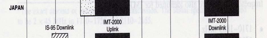


7 2 GHz Band Spectrum Allocation 7
8 Europe RACE I (Research of Advanced Communication Technologies in Europe) program started the basic 3rd generation research work in RACE II program develops the CDMA-based CODIT (Code Division Testbed) and TDMA-based ATDMA (Advanced TDMA Mobile Access) air interfaces during European research program ACTS (Advanced Communication Technologies and Services) was launched at the end of 1995 to support mobile communications research and development. Within ACTS, the FRAMES (Future Radio Wideband Multiple Access System) project was set up to define a proposal for a UMTS radio access system. Nokia, Siemens, Ericsson, France Telecom, CSEM/Pro Telecom. 8
9 Europe FRAMES wideband CDMA and wideband TDMA proposals were submitted to ETSI (European Telecommunications Standards Institute) as candidates for UMTS air interface and ITU IMT-2000 submission. After submission and presentation during 1996 and early 1997, proposals for the UMTS Terrestrial Radio Access (UTRA) air interface were grouped into five concept groups in ETSI in June Wideband CDMA (WCDMA) Wideband TDMA (WTDMA) TDMA/CDMA OFDMA ODMA 9
10 Europe In January 1998, ETSI selects WCDMA as the standard for the UTRA (UMTS Terrestrial Radio Access) air interface on the paired frequency bands, i.e. for FDD (Frequency Division Duplexing) operation, and WTDMA/CDMA for operation with unpaired spectrum allocation, i.e. for TDD (Time Division Duplexing) operation. The detailed standardization of UTRA proceeded within ETSI until the work was handed over to the 3rd Generation Partnership Project (3GPP). The technical work was transferred to 3GPP with the contribution of UTRA in early
11 Japan ARIB (the Association for Radio Industries and Businesses) was established in April 1993 to evaluate possible 3rd generation systems around three different main technologies based on WCDMA, WTDMA and OFDMA. The WCDMA technology in Japan was very similar to that being considered in Europe in ETSI. ARIB selected WCDMA, with both FDD and TDD modes operation, in WCDMA was chosen in ARIB before the process was completed in ETSI. ARIB contributed their WCDMA to 3GPP. 11
12 The United States Main standardization activities for wireless systems are carried out in TIA Engineering Committee TR45 and TR46, and in the T1 committee T1P1. TR45.5 is responsible for the IS-95, TR45.3 for the IS-136, and T1P1 with TR46 are jointly for GSM1900. Industry forums: UWCC for IS-136, CDMA Development Group (CDG) for IS-95, and the GSM Alliance and GSM North America for GSM. In April 1997, CDG issued the Advanced Systems initiative to develop the IS-95 based 3rd generation air interface proposal. In 1997, proposals from Hughes, Lucent, Motorola, Nokia, Nortel, Qualcomm, and Samsung, were submitted to TR45.5 for cdma2000, all backward compatible to IS-95. In March 1998, TR45.5 agreed on the basic framework for cdma2000: cdma2000 1x has same bandwidth as IS-95 (1.25 MHz) and cdma2000 3x, also called multicarrier CDMA, three times the bandwidth of IS
13 Korea TTA (Telecommunications Technology Association) adopted a two-track approach to the development of 3rd CDMA technology. ETRI established an R&D consortium to define the Korean proposal for IMT-2000 in 1997 and A wideband CDMA proposal has been developed within ETRI, which forms the basis for the TTA I scheme. SK Telecom (previously KMT, Korea Mobile Telecom) merged with other industrial proposals at the beginning of 1998 and formed the TTA II scheme. The TTA1 and TTA2 air interface proposals (later renamed Global CDMA 1 and 2) were based on synchronous and asynchronous wideband CDMA technologies respectively. Korean standardization efforts were later moved to 3GPP and 3GPP2 to contribute to WCDMA and cdma
14 3GPP 3GPP (3rd Generation Partnership Project) was founded in The standardization organizations involved were ARIB (Japan), ETSI (Europe), TTA (Korea), TTC (Japan) and T1P1 (USA). The partners agreed on joint efforts for the standardization of UTRA, now standing for Universal Terrestrial Radio Access. In 1999, CWTS (the China Wireless Telecommunication Standard Group) joined 3GPP and contributed technology from TD-SCDMA, a TDD-based CDMA 3rd generation technology already submitted to ITU-R earlier. 14
15 3GPP The first version of the common specification, called Release-99, was ready by the end of Within 3GPP, four different technical specification groups (TSG) were set up: Radio Access Network (RAN) TSG Core Network TSG Service and System Aspects TSG Terminals TSG 15
16 3GPP RAN TSG Within the TSGs, the one most relevant to the WCDMA technology is the RAN TSG. Radio Access Network Technical Specification Group WG 1 WG 2 WG 3 WG 4 ITU Ad Hoc Radio Layer 1 Radio Layer 2/3 Architecture & Interface Radio Performance & RF Parameters ITU Activity Co-ordination 16
17 3GPP2 Work done in TR45.5 and TTA was merged to form 3GPP2. Focused on cdma2000 Direct-Sequence (DS) and Multi- Carrier (MC) mode. This activity has been running in parallel with the 3GPP project, with participation from ARIB, TTC, and CWTS as member organizations. DS mode was abandoned. 17
18 Harmonization Phase Manufacturers and operators agreed to adopt a harmonized global 3rd generation CDMA standard consisting of three modes: Multi-Carrier (MC) mode based on the cdma2000 multi-carrier option, Direct Spread (DS) mode on WCDMA (UTRA FDD), and the Time Division Duplex (TDD) mode on UTRA TDD. UTRA FDD and TDD mode chip rate were changed from Mcps to 3.84 Mcps. 18
19 Parameters of WCDMA Channel Bandwidth: 5 MHz Duplex Mode: FDD and TDD Spread Spectrum Technique: Direct Spread Chip Rate: 3.84 MHz Frame Length: 10 ms (38400 chips/sce) Slot Length: 15 Slots per Frame (2560 chips/slot) Spreading Modulation: Balanced QPSK (downlink) and Dual-Channel QPSK (uplink) with complex spreading circuit. Data Modulation: QPSK (downlink) and BPSK (uplink). 19
20 Parameters of WCDMA Channel Coding: Convolutional code, Turbo code, and no coding. Spreading Factors: (uplink) and (downlink). Modulation symbol rates vary from 960 k symbols/s to 15 k symbols/s (7.5 k symbols/s) for FDD uplink (downlink). Spreading (downlink): OVSF sequences for channel separation. Gold sequences for cell and user separation (truncated cycle: 10 ms). Spreading (uplink): OVSF sequences for channel separation. Gold sequences for user separation (truncated cycle: 10 ms). 20
21 WCDMA vs. GSM Carrier spacing Frequency reuse factor Power control frequency Quality control Frequency diversity Packet data DL transmit diversity WCDMA 5 MHz khz Radio resource management algorithm Multipath diversity with RAKE receiver Load-based packet scheduling Supported for improving downlink capacity. GSM 200 khz Hz or lower Network planning (frequency planning) Frequency hopping. Time slot based scheduling with GPRS Not supported by standard but can be applied 21
22 WCDMA vs. IS-95 Carrier spacing Chip rate Power control Base station synchronization Inter-frequency handover WCDMA 5 MHz 3.84 Mcps 1.5 khz for both uplink and downlink. Not needed Yes IS MHz Mcps UL: 800Hz DL: slow control Needed (typically GPS) Possible but not specified Radio resource management Packet data DL transmit diversity Yes, provides required quality of service. Load-based packet scheduling Supported Not needed for speech only network Transmitted as short circuit-switched calls Not supported 22


23 Core Network Relation to the 3rd Generation Air Interface Alternatives 23
24 Wireless Information Transmission System Lab. WCDMA System Architecture Institute of Communications Engineering National Sun Yat-sen University
25 Basic Architecture of GSM 25


26 GSM Network Architecture 26
27 GPRS Architecture Channel Codec Unit (CCU) Channel Coding Radio Channel Measurements HLR Extension GPRS subscriber data routing information HLR BSS Visited MSC /VLR Gateway MSC /VLR PSTN PCU SGSN GGSN External Data Network Packet Control Unit (PCU) channel access control radio channel management data packet segmentation and re-assembly Serving GPRS Support Node (SGSN) functions comparable to VMSC/VLR Gateway GPRS Support Node (GGSN) functions comparable to GMSC 27
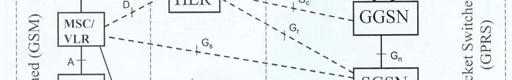
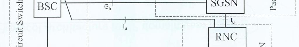
28 GPRS Interfaces SMS-GMSC SMS-IWMSC Signaling & Data Transfer E C Signaling MSC /VLR D HLR A Gs Gd Gr Gc MS Um BSS Gb SGSN Gn GGSN Gi PDN TE Gn Gp Gf SGSN GGSN other PLMN 28 EIR
29 GPRS Transmission Planes Um MS BSS Gb Gn SGSN GGSN Gi Application/ Higher level protocols Router Relay IP/ X.25 Relay IP/ X.25 IP/ X.25 SND CP LLC RLC RLC Relay BSS GP SND CP LLC BSS GP Relay GTP UDP / TCP IP GTP UDP / TCP IP IP/ X.25 IP/ X.25 L2 MAC MAC FR FR L2 L2 L2 L2 L1 GSM RF GSM RF L1 bis L1 bis L1 L1 L1 L1 BSSGP : BSS GPRS Protocol LLC : Logical Link Control SNDCP : SubNetwork Dependent FR : Frame Relayl MAC : Medium Access Control Convergence Protocol GTP : GPRS Tunnelling Protocol RLC : Radio Link Control TCP : Transmission Control Protocol IP : Internet Protocol UDP : User Datagram Protocol 29
30 GPRS Signaling Planes SGSN GGSN Gr,f,d Gc HLR, EIR, SMS-GMSC HLR SGSN Gs MSC /VLR GPRSspecific MAP extension MAP Mobile Application Part MAP Mobile Application Part BSSAP+ BSSAP+ BSS Application Part + Subset of BSSAP functionalities TCAP Transaction Capabilities Application Part TCAP SCCP Signaling Conne - ction Control Part SCCP SCCP SCCP MTP L3 MTP L3 MTP L3 MTP L3 MTP L2 MTP L2 MTP L2 MTP L2 L1 L1 L1 L1 30

31 UMTS Network Architecture 31
32 Uu Network Elements in a WCDMA PLMN Iu USIM Cu ME UE Node B Node B Node B Node B Iub UTRAN RNC Iur RNC 32 MSC/VLR SGSN GMSC HLR GGSN Core Network PLMN: Public Land Mobile Network. One PLMN is operated by a single operator. PLMN, PSTN ISDN, etc. Internet External Networks
33 The UE consists of two parts: User Equipment (UE) The Mobile Equipment (ME) is the radio terminal used for radio communication over the Uu interface. The UMTS Subscriber Identity Module (USIM) is a smartcard that holds the subscriber identity, performs authentication algorithms, and stores authentication and encryption keys and some subscription information that is needed at the terminal. 33
34 UMTS Terrestrial Radio Access Network -- UTRAN UTRAN consists of two distinct elements: The Node B converts the data flow between the Iub and Uu interfaces. It also participates in radio resource management. The Radio Network Controller (RNC) owns and controls the radio resources in its domain (the Node Bs connected to it). RNC is the service access point for all services UTRAN provides the core network (CN). 34
35 WCDMA System Architecture UMTS system utilizes the same well-known architecture that has been used by all main 2nd generation systems. The network elements are grouped into: The Radio Access Network (RAN, UMTS Terrestrial RAN = UTRAN) that handles all radio-related functionality. The Core Network (CN) which is responsible for switching and routing calls and data connections to external networks. Both User Equipment (UE) and UTRAN consist of completely new protocols, which is based on the new WCDMA radio technology. The definition of CN is adopted from GSM. 35
36 Main Elements of the GSM Core Network HLR (Home Location Register) is a database located in the user s home system that stores the master copy of the user s service profile. The service profile consists of, for example, information on allowed services, forbidden roaming areas, and Supplementary Service information such as status of call forwarding and the call forwarding number. It is created when a new user subscribes to the system. HLR stores the UE location on the level of MSC/VLR and/or SGSN. 36
37 Main Elements of the GSM Core Network MSC/VLR (Mobile Services Switching Center / Visitor Location Register) is the switch (MSC) and database (VLR) that serves the UE in its current location for circuit switched services. The MSC function is used to switch the CS transactions. The VLR function holds a copy of the visiting user s service profile, as well as more precise information on the UE s location within the serving system. 37
38 Main Elements of the GSM Core Network GMSC (Gateway MSC) is the switch at the point where UMTS PLMN is connected to external CS networks. All incoming and outgoing circuit switched connections go through GMSC. SGSN (Serving GPRS (General Packet Radio Service) Support Node) functionality is similar to that of MSC/VLR, but is typically used for Packet Switched (PS) services. GGSN (Gateway GPRS Support Node) functionality is close to that of GMSC but is in relation to PS services. 38
39 Interfaces Cu Interface: this is the electrical interface between the USIM smartcard and the ME. The interface follows a standard format for smartcards. Uu Interface: this is the WCDMA radio interface, which is the subject of the main part of WCDMA technology. This is also the most important open interface in UMTS. Iu Interface: this connects UTRAN to the CN. Iur Interface: the open Iur interface allows soft handover between RNCs from different manufacturers. Iub Interface: the Iub connects a Node B and an RNC. UMTS is the first commercial mobile telephony system where the Controller-Base Station interface is standardized as a fully open interface. 39
40 Wireless Information Transmission System Lab. UTRAN Overall Description Institute of Communications Engineering National Sun Yat-sen University
41 General Protocols Architecture The protocols over Uu and Iu interfaces are divided into two structures: User plane protocols These are the protocols implementing the actual radio access bearer service, i.e. carrying user data through the access stratum. Control plane protocols These are the protocols for controlling the radio access bearers and the connection between the UE and the network from different aspects (including requesting the service, controlling different transmission resources, handover & streamlining etc.). 41
42 User Plane The radio access bearer service is offered from service access point (SAP) to SAP by the Access Stratum. The following figure shows the protocols on the Uu and Iu interfaces that link together to provide this radio access bearer service. Non-Access Stratum Radio protocols (1) Radio protocols (1) Iu proto cols (2) Iu proto cols (2) Access Stratum UE Radio UTRAN Iu CN (Uu) 42
43 Control Plane The following figure shows the control plane (signalling) protocol stacks on Iu and Uu interfaces. CM,MM,GMM,SM Non-Access Stratum CM,MM,GMM,SM Radio protocols (1) Radio protocols (1) Iu proto cols (2) Iu proto cols (2) UE Radio (Uu) Access Stratum UTRAN Iu CN 43
44 UTRAN Architecture Core Network Iu Iu UTRAN RNS RNC Iur RNS RNC Iub Iub Iub Iub Node B Node B Node B Node B 44
45 UTRAN Architecture UTRAN consists of one or more Radio Network Subsystems (RNS), which are connected to the core network through the Iu. An RNS is a sub-network within UTRAN and consists of one Radio Network Controller (RNC) and one or more Node Bs. A Node B can support FDD mode, TDD mode, or dualmode operation. RNCs may be connected to each other via Iur interface. 45
46 UTRAN Architecture RNCs and Node Bs are connected with an Iub interface. The RNC is responsible for the Handover decisions that require signaling to the UE. A RNC may include a combining/splitting function to support combination/splitting of information streams. Inside the UTRAN, the RNCs of the Radio Network Subsystems can be interconnected together through the Iur. 46
47 Main Characteristics of UTRAN Support of UTRA and all the related functionalities. UTRAN has to support soft handover and the WCDMA-specific Radio Resource Management algorithms. UTRA stands for UMTS Terrestrial Radio Access in ETSI and Universal Terrestrial Radio Access in 3GPP. Maximization of the commonalities in the handling of packet-switched and circuit-switched data, with a unique air interface protocol stack. Use of the ATM transport as the main transport mechanism in UTRAN. 47
48 Radio Network Controller (RNC) RNC is responsible for the control of the radio resources of UTRAN. RNC interfaces with the core network (normally to one MSC and one SGSN). RNC terminates the RRC (Radio Resource Control) protocol that defines the messages and procedures between the mobile and UTRAN. RNC logically corresponds to the GSM BSC. 48
49 Logical Role of the RNC Controlling RNC (CRNC): the RNC controlling a given Node B (i.e. terminating the Iub interface towards the Node B). CRNC is responsible for the load and congestion control of its own cells. CRNC executes the admission control and code allocation for new radio links to be established in those cells. 49
50 Logical Role of the RNC In case one mobile-utran connection uses resources from more than one RNS, the RNC involved have two separate logical roles (with respect to this mobile-utran connection): Serving RNC (SRNC). Drift RNC (DRNC). Node B Node B SRNC SRNC Node B RNS Node B RNS UE Iub Iur Iu Iub Iur Iu Node B Node B DRNC DRNC Node B UTRAN RNS UE Node B UTRAN RNS 50
51 Serving RNC (SRNC) One UE connected to UTRAN has one and only one SRNC. The SRNC for one mobile is the RNC that terminates both the Iu link for the transport of user data and the corresponding RANAP (RAN application part) signaling to/from the core network. SRNC also terminates the Radio Resource Control Signaling, that is the signaling protocol between the UE and UTRAN. SRNC executes basic Radio Resource Management operations, such as handover decision, outer loop power control, and the mapping of Radio Access Bearer parameters into air interface transport channel parameters. SRNC performs L2 processing of the data to/from the radio interface. 51
52 Drift RNC (DRNC) One UE may have zero, one or more DRNCs. DRNC is any RNC, other than the SRNC, that controls cells used by the mobile. DRNC may perform macro-diversity combining. DRNC does not perform L2 processing of the user plane data. DRNC routes the data transparently between the Iub and Iur interface, except when the UE is using a common or shared transport channel. 52
53 UTRAN Functions List Transfer of User Data Radio channel ciphering and deciphering Integrity protection. Synchronization. Functions related to broadcast and multicast services. Overall system access control: Admission Control. Congestion Control. System information broadcasting. 53
54 Functions related to mobility: Handover; SRNS Relocation; Paging support; Positioning. UTRAN Functions List Functions related to radio resource management and control: Radio resource configuration and operation. Radio environment survey; Combining/splitting control. Connection set-up and release; 54
55 UTRAN Functions List Functions related to radio resource management and control (continue): Allocation and deallocation of Radio Bearers; Radio protocols function; RF power control. Radio channel coding; Channel coding control; Initial (random) access detection and handling. CN Distribution function for Non Access Stratum messages. 55
56 Serving RNS Relocation Core Network Core Network Iu Iu DRNS Iur SRNS SRNS RNS Cells UE UE Before SRNS Relocation After SRNS Relocation 56
57 Main Functions of Node B Node B perform the air interface L1 processing (channel coding, interleaving, rate adaptation, spreading, modulation, etc.). Node B performs some basic Radio Resource Management operation such as inner loop power control. Node B logically corresponds to the GSM Base Station. 57
58 Function Distribution Principles For radio resource management functionality: The CRNC owns the radio resources of a cell. The SRNC handles the connection to one UE, and may borrow radio resources of a certain cell from the CRNC. Dynamical control of power for dedicated channels, within limits admitted by CRNC, is done by the SRNC. Dynamic control on smaller time-scale for some radio links of the UE connection may be done by the Node B. This "inner loop" control is controlled by an "outer loop", for which the SRNC has overall responsibility. Data scheduling for dedicated channels is done by the SRNC, while for common channels it is done by CRNC. 58
59 Function Distribution Principles For management of node-internal resources: Each UTRAN node is considered a network element on its own. The knowledge about the equipment of a network element is kept within the network element itself and its management system. The node itself always manages node-internal resources. For transport network resource management: Management of transport network resources belong to the Transport Layer. Mechanisms relevant for the selected transport technology are used. No functional split between UTRAN nodes is specified what regards the Transport Layer. As a general guideline, the UTRAN protocols should be designed in such a way that they minimize the need for a DRNC to interpret the user plane frame protocol information other than for the combining/splitting purpose. 59
60 Mobility Management All cell level mobility should be handled within UTRAN. The cell structure of the radio network should not necessarily be known outside the UTRAN. The UE may either have or not have a signaling connection: When a signaling connection exists, the CN can reach the UE by the dedicated connection SAP on the CN side, and the UTRAN has a context with the UE and CN for this particular connection. When a dedicated connection does not exist, the CN must reach the UE via the Notification SAP. The message sent to the UE can be a request to the UE to establish a dedicated connection. 60
61 Mobility Management When there is a signaling connection exists: Depending on the activity of a UE, the location of the UE is known either on cell level (higher activity) or in a larger area consisting of several cells (lower activity). This will Minimize the number of location update messages for moving UEs with low activity. Remove the need for paging for UEs known on cell level. The UTRAN shall handle the radio interface mobility of the UE, including procedures such as soft handover. 61
62 Mobility Management Where there does not exist a dedicated connection between the UTRAN and the UE: No UE information is needed in UTRAN. Mobility is handled directly between UE and CN outside access stratum (e.g. by means of registration procedure). When paging the UE, the CN indicates a geographical area that is translated within UTRAN to the actual cells that shall be paged. 62
63 Mobility Management When a dedicated connection is released, the UE performs a new registration to the CN when needed. The UTRAN does not contain any permanent 'location registers' for the UE, but only temporary contexts for the duration of the dedicated connection. This context may typically contain location information (e.g. current cell(s) of the UE) and information about allocated radio resources and related connection references. 63
64 Synchronization Different synchronization issues are identified within UTRAN: 1. Network Synchronisation; 2. Node Synchronisation; 3. Transport Channel synchronisation; 4. Radio Interface Synchronisation; 5. Time Alignment handling. 64
65 Synchronization Issues Model Vocoder Time Alignment Handling CN RNC RNS RNC Transport Channel Synchronisation Node B Node B Node B Node B Node B Radio Interface Synchronisation [TDD] Radio Interface UE 1 Sync. UE 2 UTRAN Optional TDD only input & output sync ports 65
66 General Protocol Model for UTRAN Interface Radio Network Layer Control Plane Application Protocol Access Link Control Application Part: generic name for the transport signaling protocols used to set up and tear down transport bearers. User Plane Data Stream(s) Transport Network Layer Transport User Network Plane Transport Network Control Plane ALCAP(s) Transport User Network Plane Signalling Bearer(s) Signalling Bearer(s) Data Bearer(s) Physical Layer The structure is based on the principle that the layers and planes are logically independent of each other. Therefore, as and when required, the standardisation body can easily alter protocol stacks and planes to fit future requirements. 66
67 UTRAN Protocol Model Horizontal Layers The Protocol Structure consists of two main layers, Radio Network Layer, and Transport Network Layer. All UTRAN related issues are visible only in the Radio Network Layer. The Transport Network Layer represents standard transport technology that is selected to be used for UTRAN, but without any UTRAN specific requirements. 67
68 UTRAN Protocol Model Vertical Planes Control Plane: The Control Plane includes the Application Protocol and the Signalling Bearer for transporting the Application Protocol messages. Among other things, the Application Protocol is used for setting up bearers for (i.e. Radio Access Bearer or Radio Link) in the Radio Network Layer. In the three plane structure the bearer parameters in the Application Protocol are not directly tied to the User Plane technology. The Signalling Bearer for the Application Protocol may or may not be of the same type as the Signalling Protocol for the ALCAP. The Signalling Bearer is always set up by O&M actions. 68
69 UTRAN Protocol Model Vertical Planes User Plane: The User Plane includes the Data Stream(s) and the Data Bearer(s) for the Data Stream(s). The Data Stream(s) is/are characterised by one or more frame protocols specified for that interface. Transport Network Control Plane Used for all control signaling within the Transport Layer. Does not include any Radio Network Layer information. It includes the ALCAP protocol(s) that is/are needed to set up the transport bearers (Data Bearer) for the User Plane. It also includes the appropriate Signalling Bearer(s) needed for the ALCAP protocol(s). 69
70 UTRAN Protocol Model Vertical Planes Transport Network Control Plane: (continue) The Transport Network Control Plane is a plane that acts between the Control Plane and the User Plane. The introduction of Transport Network Control Plane makes it possible for the Application Protocol in the Radio Network Control Plane to be completely independent of the technology selected for Data Bearer in the User Plane. 70
71 UTRAN Protocol Model Vertical Planes Transport Network User Plane The Data Bearer(s) in the User Plane, and the Signalling Bearer(s) for Application Protocol, belong also to Transport Network User Plane. The Data Bearers in Transport Network User Plane are directly controlled by Transport Network Control Plane during real time operation, but the control actions required for setting up the Signalling Bearer(s) for Application Protocol are considered O&M actions. 71
CHAPTER 2 WCDMA NETWORK
 CHAPTER 2 WCDMA NETWORK 2.1 INTRODUCTION WCDMA is a third generation mobile communication system that uses CDMA technology over a wide frequency band to provide high-speed multimedia and efficient voice
IMT IMT-2000 stands for IMT: International Mobile Communications 2000: the frequency range of 2000 MHz and the year 2000
 IMT-2000 IMT-2000 stands for IMT: International Mobile Communications 2000: the frequency range of 2000 MHz and the year 2000 In total, 17 proposals for different IMT-2000 standards were submitted by regional
References. What is UMTS? UMTS Architecture
 1 References 2 Material Related to LTE comes from 3GPP LTE: System Overview, Product Development and Test Challenges, Agilent Technologies Application Note, 2008. IEEE Communications Magazine, February
ETSI TS V4.2.0 ( )
") TS 125 401 V4.2.0 (2001-09) Technical Specification Universal Mobile Telecommunications System (UMTS); UTRAN Overall Description (3GPP TS 25.401 version 4.2.0 Release 4) 1 TS 125 401 V4.2.0 (2001-09) Reference
TS 125 401 V4.2.0 (2001-09) Technical Specification Universal Mobile Telecommunications System (UMTS); UTRAN Overall Description (3GPP TS 25.401 version 4.2.0 Release 4) 1 TS 125 401 V4.2.0 (2001-09) Reference
1. Introduction to WCDMA. 1.1 Summary of the Main Parameters in WCDMA 1.2 Power Control 1.3 Softer and Soft Handovers
 UMTS WCDMA / HSPA 1. Introduction to WCDMA 1.1 Summary of the Main Parameters in WCDMA 1.2 Power Control 1.3 Softer and Soft Handovers IMT-2000 International Mobile Telecommunications 3G Frequency Allocation
Communication Networks Chapter 9: UMTS
 Communication Networks Chapter 9: UMTS o IMT-2000 o UMTS Architecture o UTRAN Architecture o UMTS Mobility Support o UMTS Development UMTS and IMT-2000 Proposals for IMT-2000 (International Mobile Telecommunications)
UMTS: Universal Mobile Telecommunications System
 Department of Computer Science Institute for System Architecture, Chair for Computer Networks UMTS: Universal Mobile Telecommunications System Mobile Communication and Mobile Computing Prof. Dr. Alexander
ETSI TS V3.1.0 ( )
") ETSI TS 125 401 V3.1.0 (2000-01) Technical Specification Universal Mobile Telecommunications System (UMTS); UTRAN Overall Description (3G TS 25.401 version 3.1.0 Release 1999) (3G TS 25.401 version 3.1.0
ETSI TS 125 401 V3.1.0 (2000-01) Technical Specification Universal Mobile Telecommunications System (UMTS); UTRAN Overall Description (3G TS 25.401 version 3.1.0 Release 1999) (3G TS 25.401 version 3.1.0
Cellular Network Planning and Optimization Part VI: WCDMA Basics. Jyri Hämäläinen, Communications and Networking Department, TKK, 24.1.
 Cellular Network Planning and Optimization Part VI: WCDMA Basics Jyri Hämäläinen, Communications and Networking Department, TKK, 24.1.2008 Outline Network elements Physical layer Radio resource management
Lecture overview. UMTS concept UTRA FDD TDD
 Lecture overview 3G UMTS concept UTRA FDD TDD 3 rd Generation of Mobile Systems Goal to create a global system enabling global roaming International Mobile Telecommunications (IMT-2000) requirements: Throughput
ICT 5305 Mobile Communications. Lecture - 6 April Dr. Hossen Asiful Mustafa
 ICT 5305 Mobile Communications Lecture - 6 April 2016 Dr. Hossen Asiful Mustafa 4 types of handover 1 2 3 4 MS MS MS MS BTS BTS BTS BTS BSC BSC BSC MSC MSC Handover decision receive level BTS old receive
CSC344 Wireless and Mobile Computing. Department of Computer Science COMSATS Institute of Information Technology
 CSC344 Wireless and Mobile Computing Department of Computer Science COMSATS Institute of Information Technology Wireless Cellular Networks: 2.5G and 3G 2.5G Data services over 2G networks GSM: High-speed
Background: Cellular network technology
 Background: Cellular network technology Overview 1G: Analog voice (no global standard ) 2G: Digital voice (again GSM vs. CDMA) 3G: Digital voice and data Again... UMTS (WCDMA) vs. CDMA2000 (both CDMA-based)
Outline / Wireless Networks and Applications Lecture 18: Cellular: 1G, 2G, and 3G. Advanced Mobile Phone Service (AMPS)
") Outline 18-452/18-750 Wireless Networks and Applications Lecture 18: Cellular: 1G, 2G, and 3G 1G: AMPS 2G: GSM 2.5G: EDGE, CDMA 3G: WCDMA Peter Steenkiste Spring Semester 2017 http://www.cs.cmu.edu/~prs/wirelesss17
Outline 18-452/18-750 Wireless Networks and Applications Lecture 18: Cellular: 1G, 2G, and 3G 1G: AMPS 2G: GSM 2.5G: EDGE, CDMA 3G: WCDMA Peter Steenkiste Spring Semester 2017 http://www.cs.cmu.edu/~prs/wirelesss17
Public Interfaces. January 2006
 Public Interfaces January 2006 1 INTRODUCTION This publication does not include interfaces within the BASE network. For clarity purposes cross reference of appropriate international standards is applied
IMT-2000 members UTRA-TDD and UTRA-FDD
 IMT-2000 members UTRA-TDD and UTRA-FDD Dr. Christian Menzel, SIEMENS AG christian.menzel@icn.siemens.de Author Siemens AG, Munich Siemens AG 2000 IMT-2000_UTRA_TDD_FDD_1 UTRA (FDD + TDD)! IMT-2000 and
3GPP: Evolution of Air Interface and IP Network for IMT-Advanced. Francois COURAU TSG RAN Chairman Alcatel-Lucent
 3GPP: Evolution of Air Interface and IP Network for IMT-Advanced Francois COURAU TSG RAN Chairman Alcatel-Lucent 1 Introduction Reminder of LTE SAE Requirement Key architecture of SAE and its impact Key
LTE systems: overview
 LTE systems: overview Luca Reggiani LTE overview 1 Outline 1. Standard status 2. Signal structure 3. Signal generation 4. Physical layer procedures 5. System architecture 6. References LTE overview 2 Standard
3GPP TS V6.1.0 ( )
") TS 25.305 V6.1.0 (2004-06) Technical Specification 3rd Generation Partnership Project; Technical Specification Group Radio Access Network; Stage 2 functional specification of User Equipment (UE) positioning
TS 25.305 V6.1.0 (2004-06) Technical Specification 3rd Generation Partnership Project; Technical Specification Group Radio Access Network; Stage 2 functional specification of User Equipment (UE) positioning
LTE Long Term Evolution. Dibuz Sarolta
 LTE Long Term Evolution Dibuz Sarolta History of mobile communication 1G ~1980s analog traffic digital signaling 2G ~1990s (GSM, PDC) TDMA, SMS, circuit switched data transfer 9,6kbps 2.5 G ~ 2000s (GPRS,
Mobile Network Evolution Part 1. GSM and UMTS
 Mobile Network Evolution Part 1 GSM and UMTS GSM Cell layout Architecture Call setup Mobility management Security GPRS Architecture Protocols QoS EDGE UMTS Architecture Integrated Communication Systems
Md. Firoz Hossain Abu Shadat Mohammad Sohab
 Mathematical Modelling of Call Admission Control in WCDMA Network Md. Firoz Hossain Abu Shadat Mohammad Sohab This thesis is presented as part of Degree of Master of Science in Electrical Engineering With
MNA Mobile Radio Networks Mobile Network Architectures
 MNA Mobile Radio Networks Mobile Network Architectures Roberto Verdone roberto.verdone@unibo.it +39 051 20 93817 Office Hours: Monday 4 6 pm (upon prior agreement via email) Slides are provided as supporting
ETSI SMG#24 TDoc SMG 903 / 97. December 15-19, 1997 Source: SMG2. Concept Group Alpha - Wideband Direct-Sequence CDMA: System Description Summary
 ETSI SMG#24 TDoc SMG 903 / 97 Madrid, Spain Agenda item 4.1: UTRA December 15-19, 1997 Source: SMG2 Concept Group Alpha - Wideband Direct-Sequence CDMA: System Description Summary Concept Group Alpha -
IMT-2000/UMTS delivering full BWA
 IMT-2000/UMTS delivering full BWA Rémi THOMAS Directeur du projet réseau UMTS d Orange France Agenda 3G and IMT 2000 Family UMTS phase 1 principles From GSM to GSM/UMTS Key Technical Characteristics of
Developing Mobile Applications
 Developing Mobile Applications GSM networks 1 carriers GSM 900 MHz 890-915 MHz 935-960 MHz up down 200 KHz 200 KHz 25 MHz 25 MHz 2 frequency reuse A D K B J L C H E G I F A 3 Reuse patterns 4/12 4 base
Content. WCDMA BASICS HSDPA In general HSUPA
 HSPA essentials Content WCDMA BASICS HSDPA In general HSUPA WCDMA Network Architecture USIM card Affected elements for HSPA GSM/WCDMA mobile Uu GSM/WCDMA mobile WCDMA mobile Uu Uu BTS BTS RAN Iub Iub RNC
CHAPTER 13 CELLULAR WIRELESS NETWORKS
 CHAPTER 13 CELLULAR WIRELESS NETWORKS These slides are made available to faculty in PowerPoint form. Slides can be freely added, modified, and deleted to suit student needs. They represent substantial
A NEW EFFICIENT HANDOVER ALGORITHM FOR MBMS ENABLED 3G MOBILE CELLULAR NETWORKS UNIVERSITY OF CYPRUS
 Master s Thesis A NEW EFFICIENT HANDOVER ALGORITHM FOR MBMS ENABLED 3G MOBILE CELLULAR NETWORKS Christopher Christophorou UNIVERSITY OF CYPRUS DEPARTMENT OF COMPUTER SCIENCE December 2005 UNIVERSITY OF
Vocoder RNS RNC. Node B. Node B UE2. Figure 1. Synchronisation issues model.
 TSG-RAN Working Group 2 (Radio layer 2 and Radio layer 3) TSGR2#2(99) 90 Stockholm 8 th to 11 th March 1999 Agenda Item: 8.7 Source: Title: Nokia UTRAN Synchronisation Document for: FYI [This contribution
CS 6956 Wireless & Mobile Networks April 1 st 2015
 CS 6956 Wireless & Mobile Networks April 1 st 2015 The SIM Card Certain phones contain SIM lock and thus work only with the SIM card of a certain operator. However, this is not a GSM restriction introduced
Mohammad Hossein Manshaei 1393
 Mohammad Hossein Manshaei manshaei@gmail.com 1393 GSM 2 GSM Architecture Frequency Band and Channels Frames in GSM Interfaces, Planes, and Layers of GSM Handoff Short Message Service (SMS) 3 subscribers
Mobilné systémy 3. generácie UMTS
 Mobilné systémy 3. generácie UMTS Ing. Matúš Turcsány, PhD. turcsany@ktl.elf.stuba.sk KTL FEI STU 2009 Prehľad prednášok UMTS HSDPA, EUL HSPA evolution LTE LTE-Advanced Nasadené technológie GSM worldwide
An Introduction to Wireless Technologies Part 2. F. Ricci
 An Introduction to Wireless Technologies Part 2 F. Ricci Content Medium access control (MAC): FDMA = Frequency Division Multiple Access TDMA = Time Division Multiple Access CDMA = Code Division Multiple
ETSI SMG#24 TDoc SMG2 898 / 97 Madrid, Spain December 15-19, 1997 Source: SMG2. Concept Group Delta WB-TDMA/CDMA: Evaluation Summary
 ETSI SMG#24 TDoc SMG2 898 / 97 Madrid, Spain December 15-19, 1997 Source: SMG2 Concept Group Delta WB-TDMA/CDMA: Evaluation Summary Introduction In the procedure to define the UMTS Terrestrial Radio Access
Mobile Communications II Chapter 5: UMTS
 Mobile Communications II Chapter 5: UMTS Universal Mobile Communication System Overview/Standardisations Architecture Data services HSPA (High Speed Packet Access) UMTS Goal to create an Universal Personal
UNIT- 2. Components of a wireless cellular network
 UNIT- 2 Components of a wireless cellular network These network elements may be divided into three groups. MS- Provides the user link to wireless network RBS, BSC The B.S system provides the wireless system
Chapter 5 3G Wireless Systems. Mrs.M.R.Kuveskar.
 Chapter 5 3G Wireless Systems Mrs.M.R.Kuveskar. Upgrade paths for 2G Technologies 2G IS-95 GSM- IS-136 & PDC 2.5G IS-95B HSCSD GPRS EDGE Cdma2000-1xRTT W-CDMA 3G Cdma2000-1xEV,DV,DO EDGE Cdma2000-3xRTT
3G Technologies. Outline. WCDMA, TD-(S)CDMA and cdma2000 Janne Kurjenniemi. Background. 3G technologies WCDMA TD-(S)CDMA. cdma2000
CDMA and cdma2000 Janne Kurjenniemi. Background. 3G technologies WCDMA TD-(S)CDMA. cdma2000") 3G Technologies WCDMA, TD-(S)CDMA and cdma2000 Janne Kurjenniemi 1 Magister Solutions 2006-11-02 / JKu Outline Background Why new radio access Frequency allocation Spread spectrum 3G technologies WCDMA
3G Technologies WCDMA, TD-(S)CDMA and cdma2000 Janne Kurjenniemi 1 Magister Solutions 2006-11-02 / JKu Outline Background Why new radio access Frequency allocation Spread spectrum 3G technologies WCDMA
GSM and WCDMA RADIO SYSTEMS ETIN15. Lecture no: Ove Edfors, Department of Electrical and Information Technology
 RADIO SYSTEMS ETIN15 Lecture no: 11 GSM and WCDMA Ove Edfors, Department of Electrical and Information Technology Ove.Edfors@eit.lth.se 2015-05-12 Ove Edfors - ETIN15 1 Contents (Brief) history of mobile
W-CDMA for UMTS Principles
 W-CDMA for UMTS Principles Introduction CDMA Background/ History Code Division Multiple Access (CDMA) Why CDMA? CDMA Principles / Spreading Codes Multi-path Radio Channel and Rake Receiver Problems to
3GPP TS V8.1.0 ( )
") TS 25.201 V8.1.0 (2008-05) Technical Specification 3rd Generation Partnership Project; Technical Specification Group Radio Access Network; Physical layer - General description (Release 8) The present document
TS 25.201 V8.1.0 (2008-05) Technical Specification 3rd Generation Partnership Project; Technical Specification Group Radio Access Network; Physical layer - General description (Release 8) The present document
Chapter 5 Acknowledgment:
 Chapter 5 Acknowledgment: This material is based on the slides formatted by Dr Sunilkumar S. Manvi and Dr Mahabaleshwar S. Kakkasageri, the authors of the textbook: Wireless and Mobile Networks, concepts
Section A : example questions
 2G1723 GSM Network and Services The exam will consist of two sections: section A (20p) and section B (8p). Section A consist of 20 multiple-choice questions (1p each), where exactly one answer is correct.
Chapter 8: GSM & CDAMA Systems
 Chapter 8: GSM & CDAMA Systems Global System for Mobile Communication (GSM) Second Generation (Digital) Cellular System Operated in 900 MHz band GSM is also operated in 1800 MHz band and this version of
2G Mobile Communication Systems
 2G Mobile Communication Systems 2G Review: GSM Services Architecture Protocols Call setup Mobility management Security HSCSD GPRS EDGE References Jochen Schiller: Mobile Communications (German and English),
Contents. UMTS Radio Access Network (UTRAN) UTRAN Architecture. Refresher: Some concepts. UTRAN Bearer Architecture.
 UTRAN Architecture. Refresher: Some concepts. UTRAN Bearer Architecture.") Contents UMTS Radio Access Network (UTRAN) T-110.498 UMTS Networks Chapter 4 Päivi Savola 4.2.2003 UTRAN Architecture Base Station Radio Network Controller Radio Resource Management, QoS Control Functions
Contents UMTS Radio Access Network (UTRAN) T-110.498 UMTS Networks Chapter 4 Päivi Savola 4.2.2003 UTRAN Architecture Base Station Radio Network Controller Radio Resource Management, QoS Control Functions
RADIO SYSTEMS ETIN15. Lecture no: GSM and WCDMA. Ove Edfors, Department of Electrical and Information Technology
 RADIO SYSTEMS ETIN15 Lecture no: 11 GSM and WCDMA Ove Edfors, Department of Electrical and Information Technology Ove.Edfors@eit.lth.se 1 Contents (Brief) history of mobile telephony Global System for
FB 1 ikom / Kommunikationsnetze
 GSM Overview Services GSM Architecture GSM Air Interface GSM Logical Channels - 2 - formerly: Groupe Spéciale Mobile (founded 1982) by CEPT (Conférence Européenne des Administrations des Postes et des
3G TECHNOLOGY WHICH CAN PROVIDE AUGMENTED DATA TRANSFER RATES FOR GSM STANDARTS AND THE MODULATION TECHNIQUES
 3G TECHNOLOGY WHICH CAN PROVIDE AUGMENTED DATA TRANSFER RATES FOR GSM STANDARTS AND THE MODULATION TECHNIQUES Mustafa ALKAN Ejder ORUÇ Nur ERZEN Özgür GENÇ malkan@tk.gov.tr eoruc@tk.gov.tr nerzen@tk.gov.tr
APPLICATION PROGRAMMING: MOBILE COMPUTING [ INEA00112W ] Marek Piasecki PhD Wireless Telecommunication
![APPLICATION PROGRAMMING: MOBILE COMPUTING [ INEA00112W ] Marek Piasecki PhD Wireless Telecommunication](/thumbs/82/86735605.jpg "APPLICATION PROGRAMMING: MOBILE COMPUTING [ INEA00112W ] Marek Piasecki PhD Wireless Telecommunication") APPLICATION PROGRAMMING: MOBILE COMPUTING [ INEA00112W ] Marek Piasecki PhD Wireless Telecommunication (W6/2013) What is Wireless Communication? Transmitting/receiving voice and data using electromagnetic
APPLICATION PROGRAMMING: MOBILE COMPUTING [ INEA00112W ] Marek Piasecki PhD Wireless Telecommunication (W6/2013) What is Wireless Communication? Transmitting/receiving voice and data using electromagnetic
ETSI TS V4.2.0 ( )
") TS 123 221 V4.2.0 (2002-06) Technical Specification Digital cellular telecommunications system (Phase 2+); Universal Mobile Telecommunications System (UMTS); Architectural requirements (3GPP TS 23.221
TS 123 221 V4.2.0 (2002-06) Technical Specification Digital cellular telecommunications system (Phase 2+); Universal Mobile Telecommunications System (UMTS); Architectural requirements (3GPP TS 23.221
LTE Aida Botonjić. Aida Botonjić Tieto 1
 LTE Aida Botonjić Aida Botonjić Tieto 1 Why LTE? Applications: Interactive gaming DVD quality video Data download/upload Targets: High data rates at high speed Low latency Packet optimized radio access
Page 1. Problems with 1G Systems. Wireless Wide Area Networks (WWANs) EEC173B/ECS152C, Spring Cellular Wireless Network
 EEC173B/ECS152C, Spring Cellular Wireless Network") EEC173B/ECS152C, Spring 2009 Wireless Wide Area Networks (WWANs) Cellular Wireless Network Architecture and Protocols Applying concepts learned in first two weeks: Frequency planning, channel allocation
EEC173B/ECS152C, Spring 2009 Wireless Wide Area Networks (WWANs) Cellular Wireless Network Architecture and Protocols Applying concepts learned in first two weeks: Frequency planning, channel allocation
Wireless and Mobile Network Architecture. Outline. Introduction. Cont. Chapter 1: Introduction
 Wireless and Mobile Network Architecture Chapter 1: Introduction Prof. Yuh-Shyan Chen Department of Computer Science and Information Engineering National Taipei University Sep. 2006 Outline Introduction
LTE (Long Term Evolution)
") LTE (Long Term Evolution) Assoc. Prof. Peter H J Chong, PhD (UBC) School of EEE Nanyang Technological University Office: +65 6790 4437 E-mail: ehjchong@ntu.edu.sg 2 Outline Introduction SAE (System Architecture
LTE (Long Term Evolution) Assoc. Prof. Peter H J Chong, PhD (UBC) School of EEE Nanyang Technological University Office: +65 6790 4437 E-mail: ehjchong@ntu.edu.sg 2 Outline Introduction SAE (System Architecture
Wireless and Mobile Network Architecture
 Wireless and Mobile Network Architecture Chapter 1: Introduction Prof. Yuh-Shyan Chen Department of Computer Science and Information Engineering National Taipei University Sep. 2006 1 Outline Introduction
Dimensioning, configuration and deployment of Radio Access Networks. part 1: General considerations. Agenda
 Dimensioning, configuration and deployment of Radio Access Networks. part 1: General considerations Agenda Mobile Networks Standards Network Architectures Call Set Up Network Roll Out Site Equipment Distributed
WCDMA UMTS Radio Access for Third Generation Mobile Communications Third Edition
 WCDMA UMTS Radio Access for Third Generation Mobile Communications Third Edition Edited by Harri Holma and Antti Toskala Both of Nokia, Finland John Wiley & Sons, Ltd Contents Preface Acknowledgements
TELECOMMUNICATION STANDARDIZATION SECTOR
 INTERNATIONAL TELECOMMUNICATION UNION TELECOMMUNICATION STANDARDIZATION SECTOR STUDY PERIOD 2001-2004 ITU-T Special Study Group on IMT-2000 and Beyond CHAIRMAN S LETTER TO EXTERNAL ORGANIZATIONS TITLE:
Macro Diversity Combining Optimisation in HSPA Flat Architecture
 HELSINKI UNIVERSITY OF TECHNOLOGY Faculty of Electronics, Communication and Automation Department of Communications and Networking Macro Diversity Combining Optimisation in HSPA Flat Architecture Petri
Requirements for GPRS Evolution Towards Providing Third Generation Services
 Requirements for GPRS Evolution Towards Providing Third Generation Services Håkan Olofsson Ericsson Radio Systems AB Outline GPRS Background GPRS Role in Future Communications Higher bit rates: EGPRS Improved
TELE4652 Mobile and Satellite Communications
 Mobile and Satellite Communications Lecture 12 UMTS W-CDMA UMTS W-CDMA The 3G global cellular standard set to supersede GSM Universal Mobile Telecommunication System (UMTS) Slow on the uptake by mid-2008
David Tipper. Graduate Telecommunications and Networking Program University of Pittsburgh
 3G: UMTS overview David Tipper Associate Professor Graduate Telecommunications and Networking Program University of Pittsburgh 2700 Slides 12 Subscriber base continues to grow 1 billion wireless subscribers
GSM and UMTS. Mobile phone subscribers worldwide. Development of mobile telecommunication systems. How does it work?
 Mobile phone subscribers worldwide approx. 1.7 bn 1600 1400 Market GSM Overview Services Sub-systems Components GSM and UMTS UMTS/IMT-2000 Subscribers [million] 1200 1000 800 600 400 200 0 GSM total TDMA
MOBILE COMPUTING 4/8/18. Basic Call. Public Switched Telephone Network - PSTN. CSE 40814/60814 Spring Transit. switch. Transit. Transit.
 MOBILE COMPUTING CSE 40814/60814 Spring 2018 Public Switched Telephone Network - PSTN Transit switch Transit switch Long distance network Transit switch Local switch Outgoing call Incoming call Local switch
Wireless Telecommunication Systems GSM as basis of current systems Enhancements for data communication: HSCSD, GPRS, EDGE UMTS: Future or not?
 Chapter 2 Technical Basics: Layer 1 Methods for Medium Access: Layer 2 Chapter 3 Wireless Networks: Bluetooth, WLAN, WirelessMAN, WirelessWAN Mobile Networks: GSM, GPRS, UMTS Chapter 4 Mobility on the
IS-95 /CdmaOne Standard. By Mrs.M.R.Kuveskar.
 IS-95 /CdmaOne Standard By Mrs.M.R.Kuveskar. CDMA Classification of CDMA Systems CDMA SYSTEMS CDMA one CDMA 2000 IS95 IS95B JSTD 008 Narrow Band Wide Band CDMA Multiple Access in CDMA: Each user is assigned
ETSI TS V3.1.0 ( )
") TS 125 201 V3.1.0 (2000-06) Technical Specification Universal Mobile Telecommunications System (UMTS); Physical layer - General description (3G TS 25.201 version 3.1.0 Release 1999) 1 TS 125 201 V3.1.0
TS 125 201 V3.1.0 (2000-06) Technical Specification Universal Mobile Telecommunications System (UMTS); Physical layer - General description (3G TS 25.201 version 3.1.0 Release 1999) 1 TS 125 201 V3.1.0
CHAPTER 7 ROLE OF ADAPTIVE MULTIRATE ON WCDMA CAPACITY ENHANCEMENT
 CHAPTER 7 ROLE OF ADAPTIVE MULTIRATE ON WCDMA CAPACITY ENHANCEMENT 7.1 INTRODUCTION Originally developed to be used in GSM by the Europe Telecommunications Standards Institute (ETSI), the AMR speech codec
3GPP TS V ( )
") TS 36.410 V12.1.0 (2014-12) Technical Specification 3rd Generation Partnership Project; Technical Specification Group Radio Access Network; Evolved Universal Terrestrial Radio Access Network (E-UTRAN);
TS 36.410 V12.1.0 (2014-12) Technical Specification 3rd Generation Partnership Project; Technical Specification Group Radio Access Network; Evolved Universal Terrestrial Radio Access Network (E-UTRAN);
3GPP TS V ( )
") TS 36.410 V10.2.0 (2011-09) Technical Specification 3rd Generation Partnership Project; Technical Specification Group Radio Access Network; Evolved Universal Terrestrial Radio Access Network (E-UTRAN);
TS 36.410 V10.2.0 (2011-09) Technical Specification 3rd Generation Partnership Project; Technical Specification Group Radio Access Network; Evolved Universal Terrestrial Radio Access Network (E-UTRAN);
Modeling and Dimensioning of Mobile Networks: from GSM to LTE. Maciej Stasiak, Mariusz Głąbowski Arkadiusz Wiśniewski, Piotr Zwierzykowski
 Modeling and Dimensioning of Mobile Networks: from GSM to LTE Maciej Stasiak, Mariusz Głąbowski Arkadiusz Wiśniewski, Piotr Zwierzykowski Modeling and Dimensioning of Mobile Networks: from GSM to LTE GSM
10EC81-Wireless Communication UNIT-6
 UNIT-6 The first form of CDMA to be implemented is IS-95, specified a dual mode of operation in the 800Mhz cellular band for both AMPS and CDMA. IS-95 standard describes the structure of wideband 1.25Mhz
An Introduction to Wireless Technologies Part 2. F. Ricci 2008/2009
 An Introduction to Wireless Technologies Part 2 F. Ricci 2008/2009 Content Multiplexing Medium access control Medium access control (MAC): FDMA = Frequency Division Multiple Access TDMA = Time Division
UMR UTC/CNRS Cellular Networks
 UMR UTC/CNRS 7253 www.hds.utc.fr Cellular Networks Enrico NATALIZIO enrico.natalizio@hds.utc.fr 1 Cellular networks - history Radio communication was invented by Nikola Tesla and Guglielmo Marconi: in
L1/L2 Handoff Considerations based on Universal Mobile Telecommunications System (UMTS)
") L1/L2 Handoff Considerations based on Universal Mobile Telecommunications System (UMTS) Steve Dick InterDigital Communications Corporation 11 November 2002 1 UTRAN Architecture 11 November 2002 2002, InterDigital
L1/L2 Handoff Considerations based on Universal Mobile Telecommunications System (UMTS) Steve Dick InterDigital Communications Corporation 11 November 2002 1 UTRAN Architecture 11 November 2002 2002, InterDigital
CDMA & WCDMA (UMTS) AIR INTERFACE. ECE 2526-WIRELESS & CELLULAR COMMUNICATION SYSTEMS Monday, June 25, 2018
 AIR INTERFACE. ECE 2526-WIRELESS & CELLULAR COMMUNICATION SYSTEMS Monday, June 25, 2018") CDMA & WCDMA (UMTS) AIR INTERFACE ECE 2526-WIRELESS & CELLULAR COMMUNICATION SYSTEMS Monday, June 25, 2018 SPREAD SPECTRUM OPTIONS (1) Fast Frequency Hopping (FFSH) Advantages: Has higher anti-jamming
CDMA & WCDMA (UMTS) AIR INTERFACE ECE 2526-WIRELESS & CELLULAR COMMUNICATION SYSTEMS Monday, June 25, 2018 SPREAD SPECTRUM OPTIONS (1) Fast Frequency Hopping (FFSH) Advantages: Has higher anti-jamming
Question Points Score Total 100
 THE UNIVERSITY OF HONG KONG FACULTY OF ENGINEERING DEPARTMENT OF COMPUTER SCIENCE CSIS 7304 The Wireless Internet and Mobile Computing (Midterm Examination) Date: July, 006 Time: 7:00pm 9:00pm Question
Communication Systems GSM
 Communication Systems GSM Computer Science Organization I. Data and voice communication in IP networks II. Security issues in networking III. Digital telephony networks and voice over IP 2 last to final
Universal Mobile Telecommunication System Handover Signalling Messages Performance
 TECHNOLOGY HORIZONS JOURNAL Vol. 2 (1), 10 Feb 2018, pp. 12-18 Received: 15 October 17 Accepted: 10 December 17 Universal Mobile Telecommunication System Handover Signalling Messages Performance Hamza
<Technical Report> Number of pages: 20. XGP Forum Document TWG TR
 XGP Forum Document TWG-009-01-TR Title: Conformance test for XGP Global Mode Version: 01 Date: September 2, 2013 XGP Forum Classification: Unrestricted List of contents: Chapter 1 Introduction
Mobile Comms. Systems. Radio Interface
 Radio Interface Multiple Access Techniques MuAT (1/23) The transmission of bidirectional information in duplex systems (uplink - UL - and downlink - DL - channels) can be done by dividing in: frequency:
ABSTRACT. SUBRAMANIAM, KAMALA. Radio Resource Management in UMTS-WCDMA Systems. (Under the direction of Professor Arne A. Nilsson).
.") ABSTRACT SUBRAMANIAM, KAMALA. Radio Resource Management in UMTS-WCDMA Systems. (Under the direction of Professor Arne A. Nilsson). Universal Mobile Telecommunications System (UMTS) is a Third Generation
ABSTRACT SUBRAMANIAM, KAMALA. Radio Resource Management in UMTS-WCDMA Systems. (Under the direction of Professor Arne A. Nilsson). Universal Mobile Telecommunications System (UMTS) is a Third Generation
GSM Capacity Enhancements, New Features, and Evolution to 3G. R. David Koilpillai and Kumar Balachandran
 GSM Capacity Enhancements, New Features, and Evolution to 3G R. David Koilpillai and Kumar Balachandran TeNeT Group, Department of Electrical Engineering, IIT Madras, Chennai 600036. Ericsson Research,
RADIO LINK ASPECT OF GSM
 RADIO LINK ASPECT OF GSM The GSM spectral allocation is 25 MHz for base transmission (935 960 MHz) and 25 MHz for mobile transmission With each 200 KHz bandwidth, total number of channel provided is 125
Introduction. Air Interface. LTE and UMTS Terminology and Concepts
 LTE and UMTS Terminology and Concepts By Chris Reece, Subject Matter Expert - 8/2009 UMTS and LTE networks are surprisingly similar in many respects, but the terms, labels and acronyms they use are very
ETSI TS V8.2.0 ( ) Technical Specification
 Technical Specification") TS 136 306 V8.2.0 (2008-11) Technical Specification LTE; Evolved Universal Terrestrial Radio Access (E-UTRA); User Equipment (UE) radio access capabilities (3GPP TS 36.306 version 8.2.0 Release 8) 1 TS
TS 136 306 V8.2.0 (2008-11) Technical Specification LTE; Evolved Universal Terrestrial Radio Access (E-UTRA); User Equipment (UE) radio access capabilities (3GPP TS 36.306 version 8.2.0 Release 8) 1 TS
Part 7. B3G and 4G Systems
 Part 7. B3G and 4G Systems p. 1 Roadmap HSDPA HSUPA HSPA+ LTE AIE IMT-Advanced (4G) p. 2 HSPA Standardization 3GPP Rel'99: does not manage the radio spectrum efficiently when dealing with bursty traffic
King Fahd University of Petroleum & Minerals Computer Engineering Dept
 King Fahd University of Petroleum & Minerals Computer Engineering Dept COE 543 Mobile and Wireless Networks Term 022 Dr. Ashraf S. Hasan Mahmoud Rm 22-148-3 Ext. 1724 Email: ashraf@ccse.kfupm.edu.sa 4/14/2003
Chapter 9 GSM. Distributed Computing Group. Mobile Computing Summer 2003
 Chapter 9 GSM Distributed Computing Group Mobile Computing Summer 2003 Overview GSM Overview Services Architecture Cell management TDMA, FDMA Orientation Handover Authentications HSCSD, GPRS Distributed
Wireless Medium Access Control and CDMA-based Communication Lesson 14 CDMA2000
 Wireless Medium Access Control and CDMA-based Communication Lesson 14 CDMA2000 1 CDMA2000 400 MHz, 800 MHz, 900 MHz, 1700 MHz, 1800 MHz, 1900 MHz, and 2100 MHz Compatible with the cdmaone standard A set
3GPP TS V6.0.0 ( )
") TS 01.01 V6.0.0 (2003-06) Technical Specification 3rd Generation Partnership Project; Technical Specification Group Services and System Aspects; Technical Specifications and Technical Reports for a GERAN-based
TS 01.01 V6.0.0 (2003-06) Technical Specification 3rd Generation Partnership Project; Technical Specification Group Services and System Aspects; Technical Specifications and Technical Reports for a GERAN-based
 www.telecom-cloud.net Harish Vadada The 3rd Generation Partnership Project (3GPP) is collaboration between groups of telecommunications associations, known as the Organizational Partners. The initial scope
3GPP TS V8.0.0 ( )
") TS 36.410 V8.0.0 (2007-12) Technical Specification 3rd Generation Partnership Project; Technical Specification Group Radio Access Network; Evolved Universal Terrestrial Access Network (E-UTRAN); S1 General
TS 36.410 V8.0.0 (2007-12) Technical Specification 3rd Generation Partnership Project; Technical Specification Group Radio Access Network; Evolved Universal Terrestrial Access Network (E-UTRAN); S1 General
Long Term Evolution (LTE)
") 1 Lecture 13 LTE 2 Long Term Evolution (LTE) Material Related to LTE comes from 3GPP LTE: System Overview, Product Development and Test Challenges, Agilent Technologies Application Note, 2008. IEEE Communications
1 Lecture 13 LTE 2 Long Term Evolution (LTE) Material Related to LTE comes from 3GPP LTE: System Overview, Product Development and Test Challenges, Agilent Technologies Application Note, 2008. IEEE Communications
)454 1 '%.%2!,!30%#43 /& 05",)#,!.$ -/"),%.%47/2+3 05",)#,!.$ -/"),%.%47/2+3. )454 Recommendation 1 INTERNATIONAL TELECOMMUNICATION UNION
454 1 '%.%2!,!30%#43 /& 05,)#,!.$ -/),%.%47/2+3 05,)#,!.$ -/),%.%47/2+3. )454 Recommendation 1 INTERNATIONAL TELECOMMUNICATION UNION") INTERNATIONAL TELECOMMUNICATION UNION )454 1 TELECOMMUNICATION STANDARDIZATION SECTOR OF ITU 05",)#,!.$ -/"),%.%47/2+3 '%.%2!,!30%#43 /& 05",)#,!.$ -/"),%.%47/2+3 )454 Recommendation 1 (Extract from the
INTERNATIONAL TELECOMMUNICATION UNION )454 1 TELECOMMUNICATION STANDARDIZATION SECTOR OF ITU 05",)#,!.$ -/"),%.%47/2+3 '%.%2!,!30%#43 /& 05",)#,!.$ -/"),%.%47/2+3 )454 Recommendation 1 (Extract from the
Simulating Mobile Networks Tools and Models. Joachim Sachs
 Simulating Mobile Networks Tools and Models Joachim Sachs Outline Types of Mobile Networks Performance Studies and Required Simulation Models Radio Link Performance Radio Network Performance Radio Protocol
Chapter 2: Global System for Mobile Communication
 Chapter 2: Global System for Mobile Communication (22 Marks) Introduction- GSM services and features, GSM architecture, GSM channel types, Example of GSM Call: GSM to PSTN call, PSTN to GSM call. GSM frame
3GPP TS V8.9.0 ( )
") TS 36.306 V8.9.0 (2013-03) Technical Specification 3rd Generation Partnership Project; Technical Specification Group Radio Access Network; Evolved Universal Terrestrial Radio Access (E-UTRA); User Equipment
TS 36.306 V8.9.0 (2013-03) Technical Specification 3rd Generation Partnership Project; Technical Specification Group Radio Access Network; Evolved Universal Terrestrial Radio Access (E-UTRA); User Equipment