InterferenceHunter MA2700A
|
|
|
- Caitlin Carter
- 6 years ago
- Views:
Transcription

1 User Guide InterferenceHunter MA2700A Handheld Direction Finding System
2
3 User Guide Interference Hunter MA2700A Handheld Direction Finding System Includes GPS and Electronic Compass Anritsu Company 490 Jarvis Drive Morgan Hill, CA USA Part Number: Revision: C Published: April 2014 Copyright 2013, 2014 Anritsu Company
4 WARRANTY The Anritsu product listed on the title page is warranted against defects in materials and workmanship for one year from the date of shipment. Anritsu s obligation covers repairing or replacing products which prove to be defective during the warranty period. Buyers shall prepay transportation charges for equipment returned to Anritsu for warranty repairs. Obligation is limited to the original purchaser. Anritsu is not liable for consequential damages. LIMITATION OF WARRANTY The foregoing warranty does not apply to Anritsu connectors that have failed due to normal wear. Also, the warranty does not apply to defects resulting from improper or inadequate maintenance, unauthorized modification or misuse, or operation outside of the environmental specifications of the product. No other warranty is expressed or implied, and the remedies provided herein are the Buyer s sole and exclusive remedies. DISCLAIMER OF WARRANTY DISCLAIMER OF WARRANTIES. TO THE MAXIMUM EXTENT PERMITTED BY APPLICABLE LAW, ANRITSU COMPANY AND ITS SUPPLIERS DISCLAIM ALL WARRANTIES, EITHER EXPRESSED OR IMPLIED, INCLUDING, BUT NOT LIMITED TO, IMPLIED WARRANTIES OF MERCHANTABILITY AND FITNESS FOR A PARTICULAR PURPOSE, WITH REGARD TO THE PRODUCT. THE USER ASSUMES THE ENTIRE RISK OF USING THE PRODUCT. ANY LIABILITY OF PROVIDER OR MANUFACTURER WILL BE LIMITED EXCLUSIVELY TO PRODUCT REPLACEMENT. NO LIABILITY FOR CONSEQUENTIAL DAMAGES. TO THE MAXIMUM EXTENT PERMITTED BY APPLICABLE LAW, IN NO EVENT SHALL ANRITSU COMPANY OR ITS SUPPLIERS BE LIABLE FOR ANY SPECIAL, INCIDENTAL, INDIRECT, OR CONSEQUENTIAL DAMAGES WHATSOEVER (INCLUDING, WITHOUT LIMITATION, DAMAGES FOR LOSS OF BUSINESS PROFITS, BUSINESS INTERRUPTION, LOSS OF BUSINESS INFORMATION, OR ANY OTHER PECUNIARY LOSS) ARISING OUT OF THE USE OF OR INABILITY TO USE THE PRODUCT, EVEN IF ANRITSU COMPANY HAS BEEN ADVISED OF THE POSSIBILITY OF SUCH DAMAGES. BECAUSE SOME STATES AND JURISDICTIONS DO NOT ALLOW THE EXCLUSION OR LIMITATION OF LIABILITY FOR CONSEQUENTIAL OR INCIDENTAL DAMAGES, THE ABOVE LIMITATION MAY NOT APPLY TO YOU. TRADEMARK ACKNOWLEDGMENTS Interference Hunter is a trademark of Anritsu Company. All rights reserved. NOTICE Anritsu Company has prepared this manual for use by Anritsu Company personnel and customers as a guide for the proper installation, operation and maintenance of Anritsu Company equipment and computer programs. The drawings, specifications, and information contained herein are the property of Anritsu Company, and any unauthorized use or disclosure of these drawings, specifications, and information is prohibited; they shall not be reproduced, copied, or used in whole or in part as the basis for manufacture or sale of the equipment or software programs without the prior written consent of Anritsu Company. UPDATES Updates, if any, can be downloaded from the Anritsu Website at: For the latest service and sales contact information in your area, please visit:
5
.")

6 CE Conformity Marking Anritsu affixes the CE Conformity marking onto its conforming products in accordance with Council Directives of The Council Of The European Communities in order to indicate that these products conform to the EMC and LVD directive of the European Union (EU). C-tick Conformity Marking Anritsu affixes the C-tick marking onto its conforming products in accordance with the electromagnetic compliance regulations of Australia and New Zealand in order to indicate that these products conform to the EMC regulations of Australia and New Zealand. Notes On Export Management This product and its manuals may require an Export License or approval by the government of the product country of origin for re-export from your country. Before you export this product or any of its manuals, please contact Anritsu Company to confirm whether or not these items are export-controlled. When disposing of export-controlled items, the products and manuals need to be broken or shredded to such a degree that they cannot be unlawfully used for military purposes.

7 Safety Symbols To prevent the risk of personal injury or loss related to product malfunction, Anritsu Company uses the following symbols to indicate safety-related information. For your own safety, please read the information carefully before operating the product. Symbols Used in Manuals Danger This indicates a risk from a very dangerous condition or procedure that could result in serious injury or death and possible loss related to product malfunction. Follow all precautions and procedures to minimize this risk. Warning This indicates a risk from a hazardous condition or procedure that could result in light-to-severe injury or loss related to product malfunction. Follow all precautions and procedures to minimize this risk. Caution This indicates a risk from a hazardous procedure that could result in loss related to product malfunction. Follow all precautions and procedures to minimize this risk. MA2700A UG PN: Rev. C Safety-1


8 Safety Symbols Used on Product and in Manuals The following safety symbols are used inside or on the product near operation locations to provide information about safety items and operation precautions. Ensure that you clearly understand the meanings of the symbols and take the necessary precautions before operating the product. Some or all of the following five symbols may or may not be used on all Anritsu products. In addition, there may be other labels attached to products that are not shown in the diagrams in this manual. This indicates a prohibited operation. The prohibited operation is indicated symbolically in or near the barred circle. This indicates a compulsory safety precaution. The required operation is indicated symbolically in or near the circle. This indicates a warning or caution. The contents are indicated symbolically in or near the triangle. This indicates a note. The contents are described in the box. These indicate that the marked part should be recycled. Safety-2 PN: Rev. C MA2700A UG
9 For Safety Danger Using the MA2700A Interference Hunter while a car is in motion could be dangerous and lead to serious accidents. Warning Always refer to the operation manual when working near locations at which the alert mark, shown on the left, is attached. If the operation, etc., is performed without heeding the advice in the operation manual, there is a risk of personal injury. In addition, the product performance may be reduced. Moreover, this alert mark is sometimes used with other marks and descriptions indicating other dangers. Warning This product can not be repaired by the operator. Do not attempt to remove the product covers or to disassemble internal components. Only qualified service technicians with a knowledge of electrical fire and shock hazards should service this product. There are high-voltage parts in this product presenting a risk of severe injury or fatal electric shock to untrained personnel. In addition, there is a risk of damage to precision components. MA2700A UG PN: Rev. C Safety-3

10 For Safety Caution Electrostatic Discharge (ESD) can damage the highly sensitive circuits in the instrument. ESD is most likely to occur as test devices are being connected to, or disconnected from, the instrument s front and rear panel ports and connectors. You can protect the instrument and test devices by wearing a static-discharge wristband. Alternatively, you can ground yourself to discharge any static charge by touching the outer chassis of the grounded instrument before touching the instrument s front and rear panel ports and connectors. Avoid touching the test port center conductors unless you are properly grounded and have eliminated the possibility of static discharge. Repair of damage that is found to be caused by electrostatic discharge is not covered under warranty. Safety-4 PN: Rev. C MA2700A UG
11 Table of Contents Chapter 1 Instrument Overview 1-1 Introduction Instrument Overview Standard Accessories Optional Accessories MA2700A Specifications Additional Documents Preventive Maintenance ESD Caution Document Conventions Contacting Anritsu Anritsu Service Centers Chapter 2 MA2700A Operation 2-1 MA2700A and Anritsu Instrument Setup Connections Anritsu Instrument Setup Compass Calibration Antenna and Filter Selection Interference Mapping Overview Appendix A Instrument Messages A-1 Introduction A-1 A-2 Self-Test A-1 A-3 Error Messages A-2 MA2700A UG PN: Rev. C Contents-1
12 Contents-2 PN: Rev. C MA2700A UG
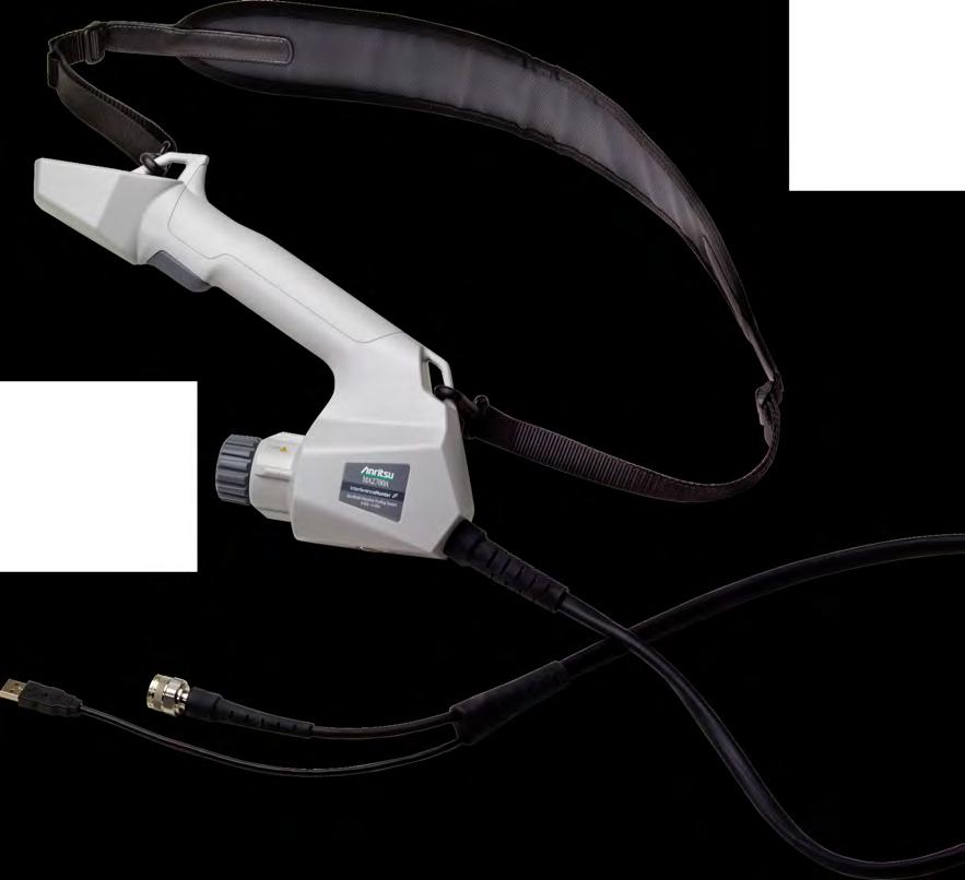
13 Chapter 1 Instrument Overview 1-1 Introduction This user guide provides an overview of the Anritsu Interference Hunter MA2700A Handheld Direction Finding System. The MA2700A allows easy-to-use handheld direction finding and includes an internal preamplifier, a GPS receiver, and an electronic compass. Connected to an Anritsu instrument, and with a directional antenna attached, the MA2700A captures location and interfering signal information when the trigger is pressed. The captured location and bearing data can be displayed on the instrument (Option 25 and SPA module V6.00 or higher required). Previous Saved Locations and Interferer Direction Current Location and Interferer Direction Location of Interferer Figure 1-1. MA2700A UG Interference Hunting Overview PN: Rev. C 1-1
. Connect directional antenna or filter and antenna combination.")
 to capture location and signal data.")
14 1-2 Instrument Overview Chapter 1 Instrument Overview 1-2 Instrument Overview USB cable, connect to Anritsu instrument. 2 Coaxial cable with type N male connector. Attach to Anritsu instrument s RF In port. 3 Coupling nut for antenna connector. 4 Antenna connector (male type N). Connect directional antenna or filter and antenna combination. Refer to Antenna and Filter Selection on page 2-4 for additional information. 5 Pulling the MA2700A trigger will prompt the Anritsu analyzer to beep. Releasing the pulled trigger has two functions: Release the trigger after the initial beep (< 1 second) to capture location and signal data. Release the trigger after the second beep (~ 2 seconds) to toggle the preamp in the MA2700A and the Anritsu analyzer s preamp On or Off. 6 Internal electronic compass and GPS receiver. 7 Included shoulder strap. 8 Internal preamplifier. 9 1/4-20 UNC tripod mount. Figure 1-2. MA2700A Overview 1-2 PN: Rev. C MA2700A UG
15 Chapter 1 Instrument Overview 1-2 Instrument Overview Standard Accessories The Anritsu MA2700A includes a shoulder strap and one year warranty. Optional Accessories The MA2700A Technical Data Sheet contains a list and descriptions of available optional accessories. The data sheet is provided with the instrument and is available on the Anritsu Web site: MA2700A Specifications Refer to the MA2700A Technical Data Sheet. MA2700A UG PN: Rev. C 1-3
16 1-3 Additional Documents Chapter 1 Instrument Overview 1-3 Additional Documents The following documents provide useful additional information when using the Interference Master MA2700A Handheld Direction Finding System. Interference Hunter MA2700A Technical Data Sheet. Includes general specifications and available accessories. The User Guide for your Anritsu instrument. Spectrum Analyzer Measurement Guide applicable for your Anritsu Instrument. The Interference Analysis chapter includes a section on Interference Mapping with information on setup and selecting the MA2700A as the Direction Finding Antenna. Anritsu easymap Tools software Help. easymap Tools creates Geo-enabled maps which are viewed on the Anritsu instruments during interference hunting. easymap Tools maps (.azm format) allow Pan and Zoom on the instrument. A complete suite of computer software applications are available for download: Directional Antennas Technical Data Sheet lists compatible antennas in many frequency bands. Details including frequency range, gain, and pattern information are provided. These documents and programs along with additional applications notes, white papers, and videos covering interference analysis are available from the Anritsu web site on the MA2700A product page. 1-4 PN: Rev. C MA2700A UG
17 Chapter 1 Instrument Overview 1-4 Preventive Maintenance 1-4 Preventive Maintenance MA2700A preventive maintenance consists of cleaning the unit and inspecting and cleaning the USB and RF connector on the instrument and all accessories. Clean the MA2700A with a soft, lint-free cloth dampened with water and a mild cleaning solution. Caution To avoid damage, do not use solvents or abrasive cleaners. Clean the coaxial cable connector with a cotton swab dampened with denatured alcohol. Visually inspect the connector. If you are unsure whether the connector is undamaged, gauge the connectors to confirm that the dimensions are correct. Carefully inspect the coaxial cable. The cable should be uniform in appearance, and not stretched, kinked, dented, or broken. 1-5 ESD Caution The MA2700A, like other high performance instruments, is susceptible to electrostatic discharge (ESD) damage. Coaxial cables and antennas may build up a significant static charge, which may damage the MA2700A. MA2700A users must always be aware of the potential for ESD damage and take all necessary precautions. Operators should exercise practices outlined within industry standards such as JEDEC-625 (EIA-625), MIL-HDBK-263, and MIL-STD-1686; which pertain to ESD and ESDS devices, equipment, and practices. It is important to remember that the operator may also carry a static charge that can cause damage. Following the practices outlined in the above standards will ensure a safe environment for both personnel and equipment. MA2700A UG PN: Rev. C 1-5
18 1-6 Document Conventions Chapter 1 Instrument Overview 1-6 Document Conventions Anritsu Instrument main menus and keypad buttons are shown in the user guide using a San Serif Bold typeface. Main menus are the buttons displayed at the bottom of the screen. Submenus and submenu buttons are displayed on the right side of the screen display and shown in the user guide using San Serif Regular typeface. Menu and button locations may be described in this document by their path: Measurement > IA Mapping The line above reads as Press the Measurement main menu, then press the IA Mapping submenu button. Note Screen captured images are provided as examples. The image and measurement details shown on your instrument may differ from the examples in this User Guide. The actual menus on your instrument may also differ based on instrument model, firmware version, and installed options. 1-7 Contacting Anritsu To contact Anritsu, please visit: From here, you can select the latest sales, select service and support contact information in your country or region, provide online feedback, complete a Talk to Anritsu form to have your questions answered, or obtain other services offered by Anritsu. Updated product information can be found on the Anritsu Web site: Search for the product model number. The latest documentation is on the product page under the Library tab. 1-6 PN: Rev. C MA2700A UG
19 Chapter 1 Instrument Overview 1-8 Anritsu Service Centers 1-8 Anritsu Service Centers For the latest service and sales information in your area, please visit the following URL: and choose a country for regional contact information. Danger Using the MA2700A Interference Hunter while a car is in motion could be dangerous and lead to serious accidents. MA2700A UG PN: Rev. C 1-7
20 1-8 Anritsu Service Centers Chapter 1 Instrument Overview 1-8 PN: Rev. C MA2700A UG
21 Chapter 2 MA2700A Operation 2-1 MA2700A and Anritsu Instrument Setup Connections 1. Connect a directional antenna to the male N-connector (inside the coupling nut). Figure 2-1. MA2700A with Attached Yagi Antenna 2. Connect the USB cable between the MA2700A and the Anritsu instrument. 3. Connect the coaxial cable between the MA2700A and the Anritsu instrument s RF Input connector. MA2700A UG PN: Rev. C 2-1
22 2-1 MA2700A and Anritsu Instrument Setup Chapter 2 MA2700A Anritsu Instrument Setup Note The Anritsu Instrument must have Interference Analysis (Option 25) and SPA module V6.00 or higher firmware to use the MA2700A and Anritsu easymap Tools. Option 31, GPS is not required when using the MA2700A for Interference Mapping. 1. Set the Instrument in Interference Analysis mode and select Interference Mapping measurement (Measurements > Interference Mapping). a. The instrument will detect the connected MA2700A and display the message MA2700 detected -- Device is ready to use. After GPS lock, the instrument will use GPS data from the MA2700A. Note Once detected, the MA2700A can be used to capture bearing and/or GPS data while in other Interference mode measurements and even other supported instrument measurement modes, including Spectrum Analyzer mode. b. Refer to the Spectrum Analyzer Measurement Guide, Interference Analyzer (Option 25) chapter, for additional information on setting the measurement parameters, manually connecting to the MA2700A, locating the interfering signal, and interference mapping. 2-2 PN: Rev. C MA2700A UG

23 Chapter 2 MA2700A Operation 2-1 MA2700A and Anritsu Compass Calibration Anritsu recommends calibrating the electronic compass before the first use and afterwards if the Anrtisu instrument connected to the MA2700A is displaying unexpected signal direction readings. 1. Press External Compass Calibration (Measurements > Interference Mapping > Direction Finding > Direction Finding Antenna Selection) and follow the onscreen instructions (Figure 2-2). Figure 2-2. Compass Calibration Note Electrical or magnetic fields can interfere with compass readings. When calibrating the compass be careful to stay well clear of electronics, high voltage power lines, magnetic devices, and masses of steel or iron. These same precautions should be taken when mapping interference. MA2700A UG PN: Rev. C 2-3
24 2-2 Antenna and Filter Selection Chapter 2 MA2700A Operation 2-2 Antenna and Filter Selection The MA2700A is designed to connect to a directional antenna that has a type N female connector at the back of the antenna s boom. To connect properly, the antenna s connector must be rigidly connected to the boom and facing toward the rear of the antenna. The connector must be at least 16 cm behind the rear-most antenna element to avoid interference between the MA2700A s body and the antenna element. A filter can be connected between the antenna and MA2700A, to reduce the impact of high level signals at other frequencies. A short filter with male and female type N connectors will work best for this application. 2-3 Interference Mapping Overview Mapping interference is a seven step process: 1. Capture a map using Anritsu easymap Tools. Refer to software help file. 2. Copy the map file to a USB memory stick and then insert the memory stick into the Anritsu instrument s USB Type A port. Anritsu recommends copying the map file to the instrument s internal memory. Refer to Anritsu instrument User Guide. Note A small percentage of USB drives are not fully compatible with Anritsu instruments. Attempting to use one of these at the same time that a MA2700A is also connected to the instrument may disrupt USB communications. The connection may be lost to the drive, the MA2700A, or both. Should this occur, try disconnecting and reconnecting the non-communicative device. For the best performance Anritsu recommends the use of an Anritsu part number R USB drive. The Status Icons described in Figure 2-3 on page 2-5 show which USB devices are currently connected. 3. Set the Anritsu instrument to IA mapping and configure the instrument settings. 4. Load (Recall) the map file from internal memory or from the USB memory stick. Refer to Spectrum Analyzer Measurement Guide. 2-4 PN: Rev. C MA2700A UG
25 Chapter 2 MA2700A Operation 2-3 Interference Mapping Overview 5. Connect the MA2700A Handheld Interference Hunter with a directional antenna to the instrument. Refer to Connections on page 2-1, as well as the Spectrum Analyzer Measurement Guide. 6. Map the interfering signal. Refer to Spectrum Analyzer Measurement Guide. 7. Save the results. Refer to Spectrum Analyzer Measurement Guide. Figure 2-3 shows an example of interference mapping where the approximate location of the interferer is determined Maximum signal level. 2 Minimum signal level. Figure 2-3. MA2700A UG Interference Mapping Overview (1 of 2) PN: Rev. C 2-5
26 2-3 Interference Mapping Overview Chapter 2 MA2700A Operation 3 Current readings from the MA2700A. Compass: Before GPS lock the compass displays a light gray M indicating magnetic north (no declination adjustment). With GPS lock, a declination adjustment is automatically applied based on location and the compass changes to display a light gray T indicating true north. The Arrow indicates the direction the MA2700A is pointing. Power level: Displays the power level at the Anritsu instrument s receiver. Bearing: Direction the MA2700A is pointing. Pitch (vertical level): Indicates the front-to-back orientation. Roll (horizontal level): Indicates the side-to-side orientation. 4 Current Anritsu instrument settings. 5 GPS lock icon. 6 Current position. 7 Status Icons (left to right). MA2700A USB connection USB memory stick available. Map auto-centering mode. 8 Zoom level indication (when using.azm maps). Top is maximum zoomed in position. Bottom is maximum zoomed out position. 9 Current tile location in base map (when using.azm maps). Move the current tile location around the base map using the arrow keys on the Anritsu analyzer. Note: Panning is not functional when the instrument displayed map is at the maximum zoomed out position. 10 Interference Mapping menus and submenus. 11 Plus sign indicates current position. 12 Previous saved locations and bearings. 13 Approximate location of the interfering signal. Figure 2-3. Interference Mapping Overview (2 of 2) Note Refer to the Spectrum Analyzer Measurement Guide for detailed information. 2-6 PN: Rev. C MA2700A UG

27 Appendix A Instrument Messages A-1 Introduction This appendix provides additional details regarding MA2700A related messages that may be displayed on the Anritsu instrument. A-2 Self-Test Perform a self-test to verify the function of the MA2700A by toggling the USB connection and pressing External Antenna Self-test. Figure A-1. MA2700A Self-test The full path from the Measurement main menu is: Measurements > Interference Mapping > Direction Finding > Direction Finding Antenna Selection > External Antenna Self-test. MA2700A UG PN: Rev. C A-1
28 A-3 Error Messages Appendix A Instrument Messages A-3 Error Messages Messages are shown below and are listed in alphabetical order. Example Message: Message Shown on Instrument: Additional details or suggestions regarding the message. 1. An external antenna is not active. Cannot run self-test. Disconnect and reconnect the MA2700A USB cable. Select the MA2700A, then attempt Self-test again. 2. Adjust Stop Frequency to 4 GHz or less to turn unit Pre Amp ON. Under the Freq main menu, select the Stop Freq button and set the frequency under 4 GHz. 3. Warning: USB connection lost to MA2700 handheld antenna. Confirm MA2700A USB connection. Reselect the MA2700A. The full path from the Measurement main menu is: Measurements > Interference Mapping > Direction Finding > Direction Finding Antenna Selection > MA2700 Handheld. 4. MA2700 Handheld Antenna not found. Disconnect and reconnect the MA2700A USB cable. Select the MA2700A. 5. Reference Level too high for Preamp. Decrease Reference Level or Increase Attenuation. When the MA2700A Preamp is turned on (using the trigger or the Antenna Preamp menu button) the firmware also attempts to turn on the Instrument s Pre Amp. Note Additional information is available in the Spectrum Analyzer Measurement Guide. A-2 PN: Rev. C MA2700A UG
29
30 Anritsu utilizes recycled paper and environmentally conscious inks and toner. Anritsu Company 490 Jarvis Drive Morgan Hill, CA USA
Power Meter. Measurement Guide. for Anritsu RF and Microwave Handheld Instruments BTS Master Site Master Spectrum Master Cell Master
 Measurement Guide Power Meter for Anritsu RF and Microwave Handheld Instruments BTS Master Site Master Spectrum Master Cell Master Power Meter Option 29 High Accuracy Power Meter Option 19 Inline Peak
Site Master Spectrum Analyzer MS2711B
 Maintenance Manual Site Master Spectrum Analyzer MS2711B Handheld Spectrum Analyzer for Measuring, Monitoring, and Analyzing Signal Environments Anritsu Company 490 Jarvis Drive Morgan Hill, CA 95037-2809
2015 RIGOL TECHNOLOGIES, INC.
 Service Guide DG000 Series Dual-channel Function/Arbitrary Waveform Generator Oct. 205 TECHNOLOGIES, INC. Guaranty and Declaration Copyright 203 TECHNOLOGIES, INC. All Rights Reserved. Trademark Information
User Guide. VNA Master MS2026B Vector Network Analyzer 5 khz to 6 GHz MS2028B Vector Network Analyzer 5 khz to 20 GHz
 User Guide VNA Master MS2026B Vector Network Analyzer 5 khz to 6 GHz MS2028B Vector Network Analyzer 5 khz to 20 GHz User Guide VNA Master Model MS202xB MS2026B Vector Network Analyzer 5 khz to 6 GHz
Type N Coaxial Calibration Kit
 User Guide Type N Coaxial Calibration Kit DC to 18 GHz Model 8850CK30/31 8850-531 (A) 3/15 User Guide Type N Coaxial Calibration Kit DC to 18 GHz Model 8850CK30/31 2900 Inland Empire Boulevard Ontario,
USER GUIDE. WR284 Waveguide TRL Calibration Kit GHz. Models: WR284C30\32 Series (Rev A) 03/16
 03/16") USER GUIDE WR284 Waveguide TRL Calibration Kit 2.60 3.95 GHz Models: WR284C30\32 Series 8770-512 (Rev A) 03/16 USER GUIDE WR284 Waveguide TRL Calibration Kit 2.60 3.95 GHz Models: WR284C30\32 Series Warranty
USER GUIDE WR284 Waveguide TRL Calibration Kit 2.60 3.95 GHz Models: WR284C30\32 Series 8770-512 (Rev A) 03/16 USER GUIDE WR284 Waveguide TRL Calibration Kit 2.60 3.95 GHz Models: WR284C30\32 Series Warranty
USER GUIDE 2.92mm Coaxial Calibration Kit
 USER GUIDE 2.92mm Coaxial Calibration Kit DC to 40 GHz Model 8770CK30/31 8770-532 (A) 03/16 USER GUIDE 2.92mm Coaxial Calibration Kit DC to 40 GHz Model: 8770CK30/31 Please note: This manual applies to
TETRIS User's Guide. High Impedance Active Probe DO177-1
 TETRIS 1500 High Impedance Active Probe User's Guide DO177-1 TETRIS 1500 Copyright 2010 Ltd. All rights reserved. Information in this publication supersedes that in all previously published material. Specifications
TETRIS 1000 High Impedance Active Probe. Instruction Manual
 TETRIS 1000 High Impedance Active Probe Instruction Manual Copyright 2015 PMK GmbH All rights reserved. Information in this publication supersedes that in all previously published material. Specifications
VT1586A Rack Mount Terminal Panel Installation and User s Manual
 VT1586A Rack Mount Terminal Panel Installation and User s Manual Manual Part Number: 82-0095-000 Rev. June 16, 2003 Printed in U.S.A. Certification VXI Technology, Inc. certifies that this product met
Current Probe Fixture Instruction Manual
 Current Probe Fixture Instruction Manual 1 TABLE OF CONTENTS INTRODUCTION 3 GENERAL INFORMATION 4 TEST METHODS 5 SAFETY 7 FIGURES 8 FORMULAS 10 MAINTENANCE 11 WARRANTY 12 2 INTRODUCTION figure 1 Mechanical
Cable and Antenna Analyzer for Anritsu s RF and Microwave Handheld Instruments
 Measurement Guide Cable and Antenna Analyzer for Anritsu s RF and Microwave Handheld Instruments Site Master Cell Master Anritsu Company 490 Jarvis Drive Morgan Hill, CA 95037-2809 USA Part Number: 10580-00241
COMBILOG ANTENNA MODEL AC MHz. rev: 0202
 COMBILOG ANTENNA 30-2000 MHz MODEL AC-220 rev: 0202 WARRANTY All equipment manufactured by Com-Power Corporation is warranted against defects in material and workmanship for a period of two (2) years from
Site Master Cable and Antenna Analyzer with Spectrum Analyzer
 Maintenance Manual Site Master Cable and Antenna Analyzer with Spectrum Analyzer S331E, 2 MHz to 4 GHz S332E, 2 MHz to 4 GHz, Spectrum Analyzer, 100 khz to 4 GHz S361E, 2 MHz to 6 GHz S362E, 2 MHz to 6
Instruction Sheet SNE SERIES. Cable Chase
 Instruction Sheet SNE SERIES Cable Chase THANK YOU Thank you for purchasing the SNE Series Cable Chase. Please read these instructions thoroughly before installing this product. PRODUCT FEATURES The 45
34134A AC/DC DMM Current Probe. User s Guide. Publication number April 2009
 User s Guide Publication number 34134-90001 April 2009 For Safety information, Warranties, Regulatory information, and publishing information, see the pages at the back of this book. Copyright Agilent
TK 100 Probe Calibrator. Instruction Manual
 TK 100 Probe Calibrator Instruction Manual Copyright 2013 PMK GmbH All rights reserved. Information in this publication supersedes that in all previously published material. Specifications are subject
Model 5100F. Advanced Test Equipment Rentals ATEC (2832) OWNER S MANUAL RF POWER AMPLIFIER
 OWNER S MANUAL RF POWER AMPLIFIER") Established 1981 Advanced Test Equipment Rentals www.atecorp.com 800-404-ATEC (2832) OWNER S MANUAL Model 5100F RF POWER AMPLIFIER 0.8 2.5 GHz, 25 Watts Ophir RF 5300 Beethoven Street Los Angeles, CA 90066
Established 1981 Advanced Test Equipment Rentals www.atecorp.com 800-404-ATEC (2832) OWNER S MANUAL Model 5100F RF POWER AMPLIFIER 0.8 2.5 GHz, 25 Watts Ophir RF 5300 Beethoven Street Los Angeles, CA 90066
MaxLite Linear Strip ECO Series
 General Safety Information To reduce the risk of death, personal injury or property damage from fire, electric shock, falling parts, cuts/abrasions, and other hazards read all warnings and instructions
Operator s Manual. PP016 Passive Probe
 Operator s Manual PP016 Passive Probe 2017 Teledyne LeCroy, Inc. All rights reserved. Unauthorized duplication of Teledyne LeCroy documentation materials is strictly prohibited. Customers are permitted
Option 10 Complex Modulation
 User Guide Option 10 Complex Modulation Waveform Download Software for the MG3690A/B/C Series Synthesized Signal Generator Anritsu Company 490 Jarvis Drive Morgan Hill, CA 95037-2809 USA Part Number: 10370-10327
User Guide. Digital AC/DC Clamp Meter Model 38394
 User Guide Digital AC/DC Clamp Meter Model 38394 Introduction Congratulations on your purchase of Extech s 38394 AC/DC Clamp Meter. This clamp meter measures AC/DC Current to 600A, DC/AC Voltage, Resistance,
Bulk Current Injection Probe Test Procedure
 Bulk Current Injection Probe Test Procedure 1 TABLE OF CONTENTS INTRODUCTION 3 GENERAL INFORMATION 4 TEST METHODS 6 SAFETY 8 FIGURES 9 FORMULAS 12 MAINTENANCE 13 WARRANTY 14 2 INTRODUCTION CURRENT PROBE
User s Guide. Digital AC/DC Clamp Meter Model 38394
 User s Guide Digital AC/DC Clamp Meter Model 38394 Introduction Congratulations on your purchase of Extech s 38394 AC/DC Clamp Meter. This clamp meter measures AC/DC Current to 600A, DC/AC Voltage, Resistance,
INSTRUCTION MANUAL. MODEL: Vintage 60R. Vintage Series Guitar Amplifi er
 INSTRUCTION MANUAL MODEL: Vintage 60R Vintage Series Guitar Amplifi er 2 INTRODUCTION Thank you for choosing this Johnson amplifier. Please read this manual carefully and completely before operating your
Planishing hammer stand For use with SKU Planishing hammer
 Planishing hammer stand For use with SKU 94847 Planishing hammer Model 96300 Assembly And Operation Instructions Please Note: Planishing Hammer not included with Stand. Due to continuing improvements,
MANUAL METAL SHRINKER/STRETCHER
 MANUAL METAL SHRINKER/STRETCHER Model 95062 ASSEMBLY AND OPERATING INSTRUCTIONS Due to continuing improvements, actual product may differ slightly from the product described herein. 3491 Mission Oaks Blvd.,
MODEL 3810/2 Line Impedance Stabilization Network
 EMC TEST SYSTEMS FEBRUARY 1996 REV C PN 399197 MODEL 3810/2 Line Impedance Stabilization Network OPERATION MANUAL USA P.O. Box 80589 Austin, Texas 78708-0589 2205 Kramer Lane, Austin, Texas 78758-4047
SPM-50 RF Spectrum Power Meter PC Software User Manual
 SPM-50 RF Spectrum Power Meter PC Software User Manual Shineway Technologies, Inc. Notices Copyright 2014, ShinewayTech, All rights reserved. No part of this manual may be reproduced in any form or by
LMR Master S412D. User Guide. An Integrated, Handheld Multi-function Land Mobile Radio Test Tool for Greater Flexibility and Technician Productivity
 User Guide LMR Master S412D An Integrated, Handheld Multi-function Land Mobile Radio Test Tool for Greater Flexibility and Technician Productivity Anritsu Company 490 Jarvis Drive Morgan Hill, CA 95037-2809
P5100A & P5150 High Voltage Probes Performance Verification and Adjustments
 x P5100A & P5150 High Voltage Probes Performance Verification and Adjustments ZZZ Technical Reference *P077053001* 077-0530-01 xx P5100A & P5150 High Voltage Probes Performance Verification and Adjustments
Sense. 3D Scanner. User Guide. See inside for use and safety information.
 Sense 3D Scanner User Guide See inside for use and safety information. 1 CONTENTS INTRODUCTION.... 3 IMPORTANT SAFETY INFORMATION... 4 Safety Guidelines....4 SENSE 3D SCANNER FEATURES AND PROPERTIES....
15 Planer Stand. Model Due to continuing improvements, actual product may differ slightly from the product described herein.
 15 Planer Stand Model 96316 Assembly And Operation Instructions Due to continuing improvements, actual product may differ slightly from the product described herein. 3491 Mission Oaks Blvd., Camarillo,
Shrinker and stretcher
 Shrinker and stretcher Model 96465 Assembly And Operation Instructions Due to continuing improvements, actual product may differ slightly from the product described herein 3491 Mission Oaks Blvd, Camarillo,
Model 3725/2M. Line Impedance Stabilization Network (LISN) User Manual
 User Manual") Model 3725/2M Line Impedance Stabilization Network (LISN) User Manual ETS-Lindgren L.P. reserves the right to make changes to any product described herein in order to improve function, design, or for any
Model 3725/2M Line Impedance Stabilization Network (LISN) User Manual ETS-Lindgren L.P. reserves the right to make changes to any product described herein in order to improve function, design, or for any
Model 9302 Amplifier-Discriminator Operating and Service Manual
 Model 9302 Amplifier-Discriminator Operating and Service Manual Printed in U.S.A. ORTEC Part No. 733690 1202 Manual Revision C Advanced Measurement Technology, Inc. a/k/a/ ORTEC, a subsidiary of AMETEK,
712B. Users Manual. RTD Calibrator. Test Equipment Depot Washington Street Melrose, MA TestEquipmentDepot.
 712B RTD Calibrator Test Equipment Depot - 800.517.8431-99 Washington Street Melrose, MA 02176 - TestEquipmentDepot.com Users Manual January 2014 2014 Fluke Corporation. All rights reserved. Specifications
GNSS-750 ANTENNA GUIDE SITE SELECTION GUIDELINES. Additional Equipment Required. Accessories
 GNSS-750 ANTENNA GUIDE OM-20000120 Rev 5 October 2012 The GNSS-750 is an active antenna designed to receive signals from the GPS, Galileo and GLONASS satellites as well as L-Band signals. This antenna
2001A. 200KHz Function Generator Instruction Manual. 99 Washington Street Melrose, MA Phone Toll Free
 2001A 200KHz Function Generator Instruction Manual 99 Washington Street Melrose, MA 02176 Phone 781-665-1400 Toll Free 1-800-517-8431 Visit us at www.testequipmentdepot.com WARRANTY Global Specialties
RIGOL. User s Guide. RP1000D Series High Voltage Differential Probe. Feb RIGOL Technologies, Inc
 User s Guide RP1000D Series High Voltage Differential Probe Feb. 2013 RIGOL Technologies, Inc Guaranty and Declaration Copyright 2012 RIGOL Technologies, Inc. All Rights Reserved. Trademark Information
FCN4760. Frequency Converter Module. User s Guide. 4.7 GHz to 6.0 GHz
 FCN4760 4.7 GHz to 6.0 GHz Frequency Converter Module User s Guide 490 JARVIS DRIVE MORGAN HILL, CA 95037-2809 P/N: 10580-00081 REVISION: C PRINTED: OCTOBER 2004 COPYRIGHT 2003-2004 ANRITSU CO. Table of
Radio Remote(s) (Installation Manual)
 (Installation Manual)") Radio Remote(s) (Installation Manual) 87 Progress Avenue, Tyngsboro, MA 01879, USA Phone (978) 649-4ECU Fax (978) 649-8363 http://www.qtiusa.com Trademarks, Version, Printing, and Copyright Trademarks
Radio Remote(s) (Installation Manual) 87 Progress Avenue, Tyngsboro, MA 01879, USA Phone (978) 649-4ECU Fax (978) 649-8363 http://www.qtiusa.com Trademarks, Version, Printing, and Copyright Trademarks
10 Ton Pull Back Ram
 10 Ton Pull Back Ram Model 97207 Set up And Operating Instructions Diagrams within this manual may not be drawn proportionally. Due to continuing improvements, actual product may differ slightly from the
Owner s Manual & Safety Instructions
 Owner s Manual & Safety Instructions Save This Manual Keep this manual for the safety warnings and precautions, assembly, operating, inspection, maintenance and cleaning procedures. Write the product s
Installation & Operation Manual SAGA1-K Series Industrial Radio Remote Control
 Installation & Operation Manual SAGA1-K Series Industrial Radio Remote Control Gain Electronic Co. Ltd. Table Of Contents Safety Considerations ------------------------------------------------------------2
POWER SENSORS (MA24XXA/B/D and MA2400XA) OPERATION MANUAL
 OPERATION MANUAL") POWER SENSORS (MA24XXA/B/D and MA2400XA) OPERATION MANUAL 490 JARVIS DRIVE MORGAN HILL, CA 95037-2809 P/N: 10585-00004 REVISION: R PRINTED: OCTOBER 2008 COPYRIGHT 1998-2008 ANRITSU CO. WARRANTY The ANRITSU
POWER SENSORS (MA24XXA/B/D and MA2400XA) OPERATION MANUAL 490 JARVIS DRIVE MORGAN HILL, CA 95037-2809 P/N: 10585-00004 REVISION: R PRINTED: OCTOBER 2008 COPYRIGHT 1998-2008 ANRITSU CO. WARRANTY The ANRITSU
TA MHz oscilloscope probe TA MHz oscilloscope probe
 TA375 100 MHz oscilloscope probe TA386 200 MHz oscilloscope probe User's Guide X1 X10 TA386 X1/X10 Max. 600 Vp Introduction This passive high-impedance oscilloscope probe is suitable for most oscilloscopes
HP 86290B RF PLUG-IN GHz HEWLETT PACKARD
 OPERATING AND SERVICE MANUAL. HP 86290B RF PLUG-IN 2.0-18.6 GHz HEWLETT PACKARD COPYRIGHT AND DISCLAIMER NOTICE Copyright - Agilent Technologies, Inc. Reproduced with the permission of Agilent Technologies
P5100A & P5150 High Voltage Probes Performance Verification and Adjustments
 x P5100A & P5150 High Voltage Probes Performance Verification and Adjustments ZZZ Technical Reference *P077053002* 077-0530-02 xx P5100A & P5150 High Voltage Probes Performance Verification and Adjustments
Model 113 Scintillation Preamplifier Operating and Service Manual
 Model 113 Scintillation Preamplifier Operating and Service Manual Printed in U.S.A. ORTEC Part No. 717560 1202 Manual Revision B Advanced Measurement Technology, Inc. a/k/a/ ORTEC, a subsidiary of AMETEK,
Broadband Current Probe Series Operation Manual
 Broadband Current Probe Series Operation Manual 1 TABLE OF CONTENTS INTRODUCTION 3 GENERAL INFORMATION 4 OPERATING INSTRUCTIONS 5 FORMULAS 6 MAINTENANCE 7 WARRANTY 8 2 INTRODUCTION CURRENT PROBE SPECIFICATIONS
Model 9305 Fast Preamplifier Operating and Service Manual
 Model 9305 Fast Preamplifier Operating and Service Manual This manual applies to instruments marked Rev 03" on rear panel. Printed in U.S.A. ORTEC Part No.605540 1202 Manual Revision B Advanced Measurement
Owner s Manual & Safety Instructions
 Owner s Manual & Safety Instructions Save This Manual Keep this manual for the safety warnings and precautions, assembly, operating, inspection, maintenance and cleaning procedures. Write the product s
USER MANUAL MODEL Time Division Multiplexor, RS-232 (CTS TDM-V.24) SALES OFFICE (301) TECHNICAL SUPPORT (301)
 SALES OFFICE (301) TECHNICAL SUPPORT (301)") USER MANUAL MODEL 3042 (CTS TDM-V.24) Time Division Multiplexor, RS-232 Part #: 07M3042-A Doc #: 119001UA Revised 3/26/01 SALES OFFICE (301) 975-1000 TECHNICAL SUPPORT (301) 975-1007 1.0 WARRANTY INFORMATION
USER MANUAL MODEL 3042 (CTS TDM-V.24) Time Division Multiplexor, RS-232 Part #: 07M3042-A Doc #: 119001UA Revised 3/26/01 SALES OFFICE (301) 975-1000 TECHNICAL SUPPORT (301) 975-1007 1.0 WARRANTY INFORMATION
14 Piece Slide Hammer and Puller Set
 Owner s Manual & Safety Instructions Save This This Manual Keep Keep this this manual manual for for the the safety safety warnings warnings and and precautions, assembly, assembly, operating, inspection,
Single Flex and Double Flex Couplings (i)
") Single Flex and Double Flex Couplings (i) FORM NO. L00G00 In accordance with Nexen s established policy of constant product improvement, the specifications contained in this manual are subject to change
Single Flex and Double Flex Couplings (i) FORM NO. L00G00 In accordance with Nexen s established policy of constant product improvement, the specifications contained in this manual are subject to change
Product Manual. Getting Started with Roadie 2.
 MOL NUMBER RD200 Product Manual Getting Started with Roadie 2. This manual is a quick start guide for Roadie 2. Please read the following instructions and conditions before using Roadie 2. For a more comprehensive
Radio Remote Controls Manual K Series
 Radio Remote Controls Manual K Series PN 52764 2010.12.20 Rev. 2 K Series radio control manual 1 Conductix Incorporated The technical data and images which appear in this manual are for informational purposes
INSTRUCTION MANUAL For LINE IMPEDANCE STABILIZATION NETWORK. Model LI khz to 10 MHz
 Page 1 of 10 INSTRUCTION MANUAL For LINE IMPEDANCE STABILIZATION NETWORK Model LI-4100 10 khz to 10 MHz Page 2 of 10 Table of Contents 1.0 Introduction... 3 2.0 Product Description... 4 3.0 Product Specifications...
Anritsu Microwave K Connector
 Instruction Sheets Anritsu Microwave K Connector K101F-R K101M-R K101M-085-R K102F-R K102M-R K103F-R K103M-R K104F-R K104M-R K110-1-R or K110-3-R K110-2-R 01-104 01-108 Anritsu Company 490 Jarvis Drive
UM DALI getting started guide. Document information
 Rev. 1 6 March 2012 User manual Document information Info Keywords Abstract Content LPC111x, LPC1343, ARM, Cortex M0/M3, DALI, USB, lighting control, USB to DALI interface. This user manual explains how
Using the USB Output Port to Charge a Device
 Table of Contents ----------------------------------- 2 Features ----------------------------------------------- 3 Controls and Functions ---------------------------------- 4 ER210 Power Sources -----------------------------------
374/375/376 Clamp Meter
 374/375/376 Clamp Meter Users Manual PN 3608883 July 2010 2010 Fluke Corporation. All rights reserved. Printed in China. Specifications are subject to change without notice. All product names are trademarks
supplied o-ring grease can be used to hold the o-ring in the groove during installation.
 42GOXX16A4-XT-1-1 ANTENNA GUIDE OM-20000158 Rev 1 December 2013 The 42G1215A-XT-1 is an active GPS antenna that receives the GPS L1 1575.42 MHz frequency, the GLONASS L1 1602 1626 MHz frequencies, the
ER200 COMPACT EMERGENCY CRANK DIGITAL WEATHER ALERT RADIO OWNER S MANUAL
 ER200 COMPACT EMERGENCY CRANK DIGITAL WEATHER ALERT RADIO OWNER S MANUAL Table of Contents -------------------------------------- 2 Features ----------------------------------------------- 3 Controls and
Current Probes. User Manual
 Current Probes User Manual ETS-Lindgren Inc. reserves the right to make changes to any product described herein in order to improve function, design, or for any other reason. Nothing contained herein shall
Instruction Sheet REB SERIES. Rotating Sliding Base REB18
 Instruction Sheet REB SERIES Rotating Sliding Base REB14 REB18 THANK YOU Thank you for purchasing the REB Series Rotating Sliding Base. Please read these instructions thoroughly before installing this
Broadband Current Probe Series Operation Manual
 Broadband Current Probe Series Operation Manual 1 TABLE OF CONTENTS WARRANTY 3 INTRODUCTION 4 GENERAL INFORMATION 5 OPERATING INSTRUCTIONS 6 FORMULAS 7 MAINTENANCE 8 2 WARRANTY INFORMATION A.H. Systems
User s Guide. Agilent 16441A R-Box. Agilent Part No Printed in Japan January Edition 4
 User s Guide Agilent 16441A R-Box Agilent Part No. 16441-90000 Printed in Japan January 2000 Edition 4 Legal Notice The information contained in this document is subject to change without notice. Copyright
PULSE OXIMETRY SIMULATOR
 PULSE OXIMETRY SIMULATOR SPO-2000 SYSTEM USER MANUAL BC BIOMEDICAL SPO-2000 SYSTEM TABLE OF CONTENTS WARNINGS, CAUTIONS, NOTICES... ii DESCRIPTION... 1 LAYOUT... 2 KEYS... 3 LED INDICATORS... 4 OPERATIONS...
PHASE ROTATION METER. Operating and Instruction Manual. a n d A C C E S S O R I E S
 PHASE ROTATION METER a n d A C C E S S O R I E S Operating and Instruction Manual HD ELECTRIC COMPANY 1 4 7 5 L A K E S I D E D R I V E WA U K E G A N, I L L I N O I S 6 0 0 8 5 U. S. A. PHONE 847.473.4980
Spectrum Master MS2721B, MS2723B, and MS2724B A High Performance Handheld Spectrum Analyzer and Base Station Analyzer
 Spectrum Master MS2721B, MS2723B, and MS2724B A High Performance Handheld Spectrum Analyzer and Base Station Analyzer User s Guide MS2721B, MS2723B, and MS2724B Spectrum Master User Guide Anritsu Company
GPS-701-GGL and GPS-702-GGL
 GPS-701-GGL and GPS-702-GGL USER GUIDE OM-20000117 Rev 2 September 2013 The GPS-701-GGL and GPS-702-GGL are active antennas designed to receive signals from the GPS and GLONASS satellites as well as L-Band
Operator s Manual. PP022 Passive Probe
 Operator s Manual PP022 Passive Probe 700 Chestnut Ridge Road Chestnut Ridge, NY, 10977-6499 Tel: (845) 425-2000, Fax: (845) 578 5985 teledynelecroy.com PP022 Passive Probe Instruction Manual 2017 Teledyne
9 PIECE TUNGSTEN CARBIDE HOLE SAW KIT. Model 90721
 9 PIECE TUNGSTEN CARBIDE HOLE SAW KIT Model 90721 Set up And Operating Instructions Diagrams within this manual may not be drawn proportionally. Due to continuing improvements, actual product may differ
Double-Ridged Waveguide Horn Antennas
 Models 3112, 3106B, 3119, 3115, 3117, 3116C Double-Ridged Waveguide Horn Antennas User Manual ETS-Lindgren Inc. Although the information in this document has been carefully reviewed and is believed to
TED-Kit 2, Release Notes
 TED-Kit 2 3.6.0 December 5th, 2014 Document Information Info Content Keywords TED-Kit 2, Abstract This document contains the release notes for the TED-Kit 2 software. Contact information For additional
Instruction Sheet D-CPU. Secure CPU Holder
 Instruction Sheet D-CPU Secure CPU Holder I-00457 Rev A PARTS LIST NOTE: Select Security Components when a more secure application is desired. Mounting Track with Mounting Tape Security Bracket Assembly
Operator s Manual. PP017 and PP018 Passive Probes
 Operator s Manual PP017 and PP018 Passive Probes 700 Chestnut Ridge Road Chestnut Ridge, NY, 10977-6499 Tel: (845) 425-2000, Fax: (845) 578 5985 teledynelecroy.com PP017 and PP018 Passive Probes Operator
A-16D A-Net Distributor
 A-16D A-Net Distributor For use with the Personal Monitor Mixing System Information in this document is subject to change. All rights reserved. Copyright 2003 Aviom, Inc. Printed in USA Document Rev. 1.03
Broadband Step-Up Transformer. User Manual
 Broadband Step-Up Transformer User Manual 990-1930 09/2004 Introduction Introduction About this unit The APC Step-Up Transformer provides 220 V power from 60 VAC Broadband cable systems. Safety Electrical
o-ring grease can be used to hold the o-ring in the groove during installation.
 42G1215A-XT-1 ANTENNA GUIDE OM-20000152 Rev 1 December 2013 The 42G1215A-XT-1 is an active antenna designed to operate at the GPS L1 and L2 frequencies, 1575.42 and 1227.60 MHz. The antenna is aircraft
Field Hub Installation Guide. P/N Rev. C 05/15
 Field Hub Installation Guide P/N016-0171-380 Rev. C 05/15 E21714 Copyright 2015 Disclaimer While every effort has been made to ensure the accuracy of this document, Raven Industries assumes no responsibility
o-ring grease can be used to hold the o-ring in the groove during installation.
 42G1215A-XT-1-2 and 42G1215A-XT-1-3 ANTENNA GUIDE OM-20000154 Rev 1 December 2013 The 42G1215A-XT-1-3 and 42G1215A-XT-1-2 are active antennas designed to operate at the GPS L1 and L2 frequencies, 1575.42
COMMERCIAL TRANSMITTER INSTRUCTIONS
 READ THIS MANUAL CAREFULLY BEFORE BEGINNING COMMERCIAL INSTRUCTIONS MODELS: 831, 8833 OCS: 1-DOOR 733, 8833C OCS: 3-DOOR 639: 9-DOOR 535: 27-DOOR PRODUCT FEATURES Allstar Commercial Transmitters are designed
30 Bending Brake. Model Assembly and Operating Instructions. Distributed exclusively by Harbor Freight Tools.
 30 Bending Brake Model 41311 Assembly and Operating Instructions Distributed exclusively by Harbor Freight Tools. 3491 Mission Oaks Blvd., Camarillo, CA 93011 Copyright 1999 by Harbor Freight Tools. All
9 QUICK RELEASE WOODWORKING VISE
 9 QUICK RELEASE WOODWORKING VISE 94386 OPERATING INSTRUCTIONS Due to continuing improvements, actual product may differ slightly from the product described herein. 349 Mission Oaks Blvd., Camarillo, CA
SHRINKER/STRETCHER SET Create radius bends and contours in sheet metal
 Owner s Manual & Safety Instructions Save This Manual Keep this manual for the safety warnings and precautions, assembly, operating, inspection, maintenance and cleaning procedures. Write the product s
Important Safety Information
 USER MANUAL Important Safety Information Before using Zuma R300, please be sure to read all operating instructions carefully. Read, follow, and keep these instructions. Heed all warnings. Do not expose
MedRx Avant Polar HIT AH-I-MPHITS-5 Effective 11/07/11
 INSTALLATION MANUAL 2 Contents Getting To Know Your AVANT POLAR HIT TM... 4 Setting up the System... 6 Software Installation... 7 Driver Installation Windows 7... 10 Driver Installation Windows XP... 13
UM DALI getting started guide. Document information
 Rev. 2 6 March 2013 User manual Document information Info Content Keywords LPC111x, LPC1343, ARM, Cortex M0/M3, DALI, USB, lighting control, USB to DALI interface. Abstract This user manual explains how
ELECTROSURGICAL UNIT ANALYZER
 ELECTROSURGICAL UNIT ANALYZER ESU-2000A USER MANUAL BC BIOMEDICAL ESU-2000A TABLE OF CONTENTS WARNINGS, CAUTIONS, NOTICES... ii DESCRIPTION... 1 OVERVIEW... 2 OPERATING INSTRUCTIONS... 3 MANUAL REVISIONS...
Signal Generators for Anritsu RF and Microwave Handheld Instruments
 Measurement Guide Signal Generators for Anritsu RF and Microwave Handheld Instruments BTS Master Spectrum Master Tracking Generator Option 20 Vector signal Generator Option 23 Anritsu Company 490 Jarvis
TMP40. User Manual.
 TMP40 User Manual www.audac.eu ADDITIONAL INFORMATION This manual is put together with much care, and is as complete as could be on the publication date. However, updates on the specifications, functionality
INSTRUCTION MANUAL INF Fax: (503)
") INSTRUCTION MANUAL INF151 1-800-547-5740 Fax: (503) 643-6322 www.ueiautomotive.com email: info@ueitest.com Introduction Congratulations on your purchase of the INF151 infrared thermometer. Like all UEi
INSTRUCTION MANUAL INF151 1-800-547-5740 Fax: (503) 643-6322 www.ueiautomotive.com email: info@ueitest.com Introduction Congratulations on your purchase of the INF151 infrared thermometer. Like all UEi
Model 3101, 3102 and 3103 Conical Log-Spiral Antennas
 Model 3101, 3102 and 3103 Conical Log-Spiral Antennas MANUAL EMC TEST SYSTEMS, L.P. SEPTEMBER 2002 EMC Test Systems, L.P. reserves the right to make changes to any products herein to improve functioning,
Model DB Disc Caliper Brake AIR CHAMP PRODUCTS. User Manual. (i) MTY (81)
 MTY (81)") DIST. AUTORIZADO MEX (55) 53 63 3 3 QRO (44) 95 7 60 MTY (8) 83 54 0 8 AIR CHAMP PRODUCTS User Manual Model DB Disc Caliper Brake (i) FORM NO. L-00-G-030 MEX (55) 53 63 3 3 MTY (8) 83 54 0 8 DIST. AUTORIZADO
DIST. AUTORIZADO MEX (55) 53 63 3 3 QRO (44) 95 7 60 MTY (8) 83 54 0 8 AIR CHAMP PRODUCTS User Manual Model DB Disc Caliper Brake (i) FORM NO. L-00-G-030 MEX (55) 53 63 3 3 MTY (8) 83 54 0 8 DIST. AUTORIZADO
GPS-703-GGG and GPS-703-GGG-N
 GPS-703-GGG and GPS-703-GGG-N USER GUIDE GM-14915086 Rev 4 April 2014 The GPS-703-GGG and GPS-703-GGG-N are active antennas designed to operate at the GPS L1 frequency at 1575.42 MHz, the GPS L2 frequency
UM Slim proximity touch sensor demo board OM Document information
 Rev. 1 26 April 2013 User manual Document information Info Keywords Abstract Content PCA8886, Touch, Proximity, Sensor User manual for the demo board OM11052 which contains the touch and proximity sensor
374/375/376 Clamp Meter
 374/375/376 Clamp Meter Users Manual PN 3608883 July 2010 2010 Fluke Corporation. All rights reserved. Printed in China. Specifications are subject to change without notice. All product names are trademarks