Digital Tachometers/Sensors and Peripherals. LG/SP/MP/RP series FV/FT/PA/TM series
|
|
|
- Thomasine Chapman
- 5 years ago
- Views:
Transcription

1 Digital Tachometers/Sensors and Peripherals LG/SP/MP/RP series FV/FT/PA/TM series
2 Select the rotation detector/rotation display unit that is optimal for your needs from the wide range of products that Ono Sokki is proud to offer. Rotation Detector Selection Guide When using a rotary encoder with a 2 VDC drive Tachometer TM- series (P.8-2) TM- (P.2) Cable (P.- ) Rotary Encoder-Features a) Small rotation torque b) Capable of measuring large P/R values; wide selection range c) Can perform detection of low-speed rotations (close to zero) d) Choice of two types of power supply depending on the model, AC or DC e) Wide selection of models for different applications Rotary Encoder SP-ZA (P.7) Photoelectric Rotation Detector Measures the rotation speed either by utilizing the light reflected from reflective tape, or from the contrast in the light received that is caused by the color of the shaft or by a difference in level. Photoelectric Rotation Detector- Features a) Sensing is performed with minimal load on the rotating shaft. b) Since output is generally performed through an amplifier, the waveform is constant and stable. Coupling (P.) Cable (P.-) Digital Tachometer TM- series (P.8-2) TM- (P.2) Cable (P.- ) Tachometer TM- series (P.8-2) Cable (P.-) Cable (P.- ) Photoelectric Rotation Detector LG-92/9 (P.) FS-/2/, FG- (P.) Reversible Counter RV- (P.29) Roller Encoder RP-7 series (P.28) Digital Tachometer TM- series (P.8-2) TM- (P.2) Electromagnetic Rotation Detector (Internal Gear Type) MP-8 series (P.) Coupling (P.) Line Speedometer This is a roller-type detector that can measure speed simply by being applied to the running line. Handheld Digital Tachometer HT series (P.2-27) Electromagnetic Rotation Detector (Internal Gear Type)- Features a) Easy detection by direct connection to the rotating shaft. A flexile coupling is recommended for the direct connection method. b) Non-contact detection provided inside the detector. c) Superb rigidity and environmental resistance; high durability d) No power supply required. e) Provides stable measurement, particularly at the lower limit of the measurement range, when compared to the external gear type. Roller Encoder RP-7 series (P.28) Cable (P.- ) Contact type Non-contact type Electromagnetic Rotation Detector The principle is the same as that for a generator where the magnet and coil are unified. If the detector is brought near the vicinity of a rotating object such as a ferromagnetic gear with protuberances, the detector's magnetic force is affected, and an alternating current with peaks corresponding to the number of teeth is generated. If the number of gear teeth is, the detector becomes a P/R rotation detector. Correct electromagnetic detector waveform Electromagnetic Rotation Detector External Gear Type)- Features a) Non-contact detection enables measurement even of high-speed rotations b) Superb rigidity and environmental resistance; high durability c) No power supply required (excluding MP-98, 982, AP-98) d) P/R selectable ( the number of detector gear teeth becomes the P/R value) e) The mounting position is enabled simply by attaching the gear to the target measurement object. Electromagnetic Rotation Detector External Gear Type) MP-9/9 series (P.7-) Cable (P.- ) Detection gear Magnetoelectric Rotation Detector (External Gear Type) MP-98/982 (P.2) AP-98 (P.2) Magnetoelectric Rotation Detector (External Gear Type) It incorporates a magneto-resistive element, a permanent magnet, a DC amplifier, and a voltage regulator inside, and is a magnet responsive type (its counter value varies depending on magnetic flux). Can detect as a square wave output of the same amplitude from ultra low speed to high speed. Hi Digital Tachometer TM- series (P.8-2) TM- (P.2) Lo Digital Tachometer TM- series (P.8-2) TM- (P.2) Correct waveform of magnetoelectric type rotation detector (Note) Rotation display value on the tachometer indicates rotation speed. 2


3 Rotation Display Unit Selection Guide For General-Purpose Model Multifunction Model Advanced Model Appearance Model No. TM- TM-2 TM- TM- TM- FT-2 Output, Specifications, etc. Display only BCD output Analog output Comparator output BCD output Analog output Comparator output RS-22C 2-channel calculation Analog output Comparator output Pulse output RS-22C FFT calculation Power Requirement (Power Supply for the Detector) to 2 VAC (2 VDC/ ma) to 2 VAC ( VDC/ ma) (Total of A and B channels) (2 VDC / ma) (For each A and B channel) to 2 VAC (2 VDC/ ma) Note: Please refer to "Table of Signal Cable" on page and to select the suitable signal cable. Note2: Please contact your nearest distributors or Ono Sokki sales office for the separated brochures of FT-2. Compatible Detectors MP series SP-ZA LG series RP series MP series LG series RP series FT- (Rotation detector for DC motor) Sound/vibration sensors Page No. p. 8-2 p. 2 p Rotation Detector Selection Guide 2, Rotation Display Unit Selection Guide Rotation Detector Notes on Detection Gears Electromagnetic Type Rotation Detector 7 Electromagnetic Type (External Gear Type) [Modules to ] General-purpose type MP-9 7 to With a directly attached cable MP-9 7 to Measurable for high speed rotation MP-92 7 to Oil-proof type MP-9 7 to Oil-proof/Heat-resistant type MP-9 7 to (up to C) Heat-resistant type MP-9 7 to (up to 22 C) Long body type ( mm) MP-9A 7 to Long body type (8 mm) MP-9 7 to Compact type (M2) MP-9 7 to Compact type (M8) MP-92 7 to Ultra-compact type (M) MP to [Compact module] For modules. to MP-92 7 to [Medium module] For modules to MP-9 7 to Magnetoelectric Type (External Gear Type) Low-to-medium speeds MP-98 2 High speeds MP Acid-proof/water proof AP-98 2 Electromagnetic Type (Built-in Gear Type) Low-to-medium speed MP-8/82/8/87B Photoelectric Type Compact type LG-92 Long distance detection LG-9 Optical Fiber FS-/2/, FG- CONTENTS Handheld Tachometer Advanced handheld tachometer FFT calculation type FT-72 2 Handheld Digital Tachometer Multifunction type HT- 2 General-purpose use (contact) HT-2 2 General-purpose use (non-contact) HT-2 2 Speedometer HT- 27 High rotation speed HR-8 27 Related Products Elevator Speedometer Handheld type EC-2 28 Line Speedometer (Roller Encoder) Low-to-medium speed RP-7 series 28 Length Meter Reversible counter RV- 29 F/V Converter General-purpose type FV- High response type FV- Isolated Signal Amplifier Signal amplifier PA- 2 Signal amplifier PA-Z 2 Coupling Selection Guide Table of Signal Cable, Application Application Rotary Encoders Ultra-compact type SP-ZA 7 Rotation Display Unit General-purpose Use Display only TM- 8 to 2 BCD output TM-2 8 to 2 Analog output TM- 8 to 2 Comparator output TM- 8 to 2 Multifunction Type Multifunction tachometer TM- 2 Advanced Model Advanced tachometer FT-2 22, 2
 is used as a detection gear, which has magnetic body and large magnetic permeability. Shape of a Detection Gear Fig.")

4 Rotation Detectors Notes on Detection Gears Notes on Detection Gears Rotation Detector Detection Gear In general, gear made with soft metals (SC, SS, etc.) is used as a detection gear, which has magnetic body and large magnetic permeability. Shape of a Detection Gear Fig. shows detector output waveforms from various types of external rotors (detection gears etc.) Involute gear is the most suitable for detection gear. *Note. Distortion might appear in output waveform, such as high frequency distortion when triangular teeth / square teeth / round teeth / partially missing teeth are used. 2. If the gear is magnetized, output voltage decreases or the abnormal waveform is output due to interference with the permanent magnet inside the detector. Abbreviation of gears: M=Module Z number of teeth D= diameter of gear M = D Z+2 N (r/min) Z (number of teeth) (s) = C (Hz) When Z=, N=C Shape of the gear for the MP-98 and the mounting method () Output signals according to the shape of the gear (2) Mounting method (A) Involute gear (B) Spur gear (C) Custom gear or Amp waveform Output waveform Amp waveform Output waveform Amp waveform Output waveform Since two pulses may be output for one tooth in the case of (B) and (C) in the figure above, (B) and (C) are not suitable for use as a detection gear. Magnet coil yoke Low magneto-resistant position gear Magnet (A) M=2 M= MP-98 Electromagnetic Rotation Detectors (MP-9/MP-9 series) (B) MP-98 2 units Detector Detector Detector Detector Fig. Various teeth shapes and output waveforms Please avoid the mounting configurations shown in the figures left, as they will cause reciprocal magnetic interference. In the case of (A), a gear with a different module is mounted in the vicinity of the MP-98. In the case of (B), two or more MP-98 units are mounted within the vicinity of one gear. () How to use a custom gear () How to use a gear when M = or more coil yoke High magneto-resistant position Electromagnetic Rotation Detector generates frequency signal of proportional to the rotation speed by bringing it close to the tooth tip of the detection gear attached to the rotating shaft. It consists of a permanent magnet, a detection coil, and a yoke. When a magnetic material approaches in the vicinity of the yoke, the magnetic flux passing through the detection coil changes, and an induced voltage of frequency proportional to the change is generated in the detection coil. Magnetic flux pulsates "frequency f = rotation speed x gear". Therefore, this will be output as the rotation signal of the detector. Features are as follows.. Easy structure 2. No power supply required. Compact. No need for maintenance It provides reliable rotation measurement and is widely used in many ways. P/R Reduce the tooth width to 2 mm or less () How to calculate Module M This calculation is for involute gears only Reference pitch circle diameter Module M = Number of teeth gear 2 mm (Example) M = D = 8 Z = P/R Reduce the tooth width this dimension to 2mm or less Electromagnetic Rotation Detectors and Magnetoelectric Rotation Detectors Magnetoelectric Rotation Detectors (MP-98/982, AP-98) V R R R2 Magnetoresistive element DC Amp Waveform shaping V Regulator VIN: DC2 V±2V Output circuit LED Drive circuit Output Magneto-electric rotation detector is made by applying a magneto-resistive element whose resistance value varies depending on the intensity of the magnetic field. Normally, a constant magnetic field is applied by a magnet, and the change in the magnetic field when the detection gear approaches the element is detected as a change in the resistance value. Changes in resistance value (= differential output) is detected and its signal is amplified by a DC amplifier. The output of the DC amplifier goes through a waveform shaping circuit and is made into a rectangular wave. Magneto-resistive element is arranged at the tip of the detector. For correct detection, it is necessary that the detection surface and the gear surface face each other with the proper direction and position. As a guide, the detector is marked with an alignment mark. (power supply: DC 2 ± 2 V) IND Electromagnetic Type Rotation Detector MP-9/9 series By bringing the MP-9/9 series close to the tooth tip, it detects the frequency signal proportional to the rotation speed (sine wave output). You can select according to the purpose from wide selection, such as general purpose type, special type including oil proof / heat resistant type. Extension cable, signal cable, connector are sold separately (See P, ). General-purpose type MP-9 Low cost and popular type Direct attached cable type MP-9 Cable m direct attached type of MP-9 (cable: D-2V) Low impedance (high-speed rotation type) MP-92 Noise-resistant due to low impedance Adapted for detection in high speed range Same size as MP-9 Oil-proof type MP-9 Conforms to Japan Electrical Manufacturers Association (JEM) standard (old), JEM--98* oil proof type Direct attached cable. m Oil proof and heat-resistant type MP-9 Conforms to Japan Electrical Manufacturers Association (JEM) standard (old), JEM--98*, oil proof type Heat resistant cable up to C m directly attached type Heat resistant type MP-9 Heat resistant up to 22 C Heat resistant cable m directly attached type Long body type MP-9A Long body type of mm mounting section, suitable for the rotation detection of the rotating object deeply installed. Long body type MP-9 Long body type of 8 mm mounting section, suitable for the rotation detection of the rotating object deeply installed. Mounting screw size is same as MP-9 Directly attached cable. m * Protective type F: Not affected harmful by oil droplets/oil spill from any direction. Mounting method Detection gear Detector Mounting fixture (not included) Compact type MP-9 Compact (M2), directly attached cable. m Compact type MP-92 Compact (M8), directly attached cable. m Ultra-compact type MP-992 Ultra-compact (M), directly attached cable. m Compact module type MP-92 For module. to Medium module type MP-9 For module to Standard detection gear MP- (ø = 2) Module, teeth Non-contact type Gap Different depending on the model (See P.9). to mm * When the electromagnetic type rotation detector MP series is used especially in the place where great importance is placed on reliability, the technical consultation is required. Please consult your nearest distributor or Ono Sokki sales office nearby. Rotation Detectors External Gear Type 7
5 Rotation Detectors External Gear Type MP-9/9 series specifications Detectors General-purpose General-purpose Low impedance Oil-proof Oil-proof/Heat- Heat-resistant (With cable (High-speed (With cable resistant ( C) (22 C) attached) rotation type) attached) (With cable attached) (With cable attached) Items MP-9 MP-9 MP-92 MP-9 MP-9 MP-9 DC resistance value (Ω)* 8 to 9 8 to 8 to 9 to 7 8 to 9 Inductance (mh) khz, T.Y.P 27 7 Impedance (Ω) khz, T.Y.P 2 k 2 2 k.8 k 2. k Output voltage (Vp-p) khz, T.Y.P * 2 2. or more Detectable frequency range (Hz) *, * 2 to, 2 to 8, 2 to, to, Detecting gear module to Operating temperature range - to 9 C - to C - to 22 C Vibration resistance (m/s 2 )* 9 Shock resistance (m/s 2 )*,9 The relationship between the gap and detection rotation speed () The relationship between the gap from the detector to the detection gear and the detection range (lowest measurable value) is given in the tables below. (2) The rotation speed range is that for which an output voltage of. Vp-p or more can be maintained. (load resistance = kω) () The rotation speed that can be measured varies according to the type of display unit used. MP-9/9 series measureable rotation speed (r/min) Lower limit of rotation speed Model Module M= M=. M=2 Gap... * When using a detection gear with teeth Upper limit of rotation speed MP- 9 2, 9 2, , 9 2, Rotation Detectors External Gear Type (g) Approx. 9 Approx. Approx. 9 Approx. (Including cable) (Including cable) Surrounding magnetic field (T). or less.2 or less 9 2 7, 9 7, 9A 2 8, Detectors Long body Long body Compact type Compact type Ultra-compact type For small For medium (With cable (With cable (With cable (With cable modules modules attached) attached) attached) attached) Items MP-9A MP-9 MP-9 MP-92 MP-992 MP-92 MP-9 9, 9 2, , DC resistance (Ω)* to 2. to 2. k.2 to. k to 9 8 to 9.7 to k Inductance (mh) khz, T.Y.P Model Module M= M=. M=2 Gap Upper limit of rotation speed Impedance (Ω) khz, T.Y.P.8 k. k 2. k 2 2 k k MP , Output voltage (Vp-p) khz, T.Y.P * 2 2. or more. or more. or more. or more (M=.7) 2. or more Detectable frequency range (Hz)*, * to, to, to, to, to, Detecting gear module to. to to Model Module M=. M=.7 Gap.2.2. Upper limit of rotation speed Operating temperature range - to 9 C - to 2 C - to 9 C MP- 92 2,,, Vibration resistance (m/s 2 )* 9 7 Shock resistance (m/s 2 )*,9 (g) Approx. Approx. 9 Approx. 7 Approx. Approx. Approx. 9 Approx. 2 (Including cable) (Including cable) (Including cable) (Including cable) Model Module M= M= M=7. Gap Upper limit of rotation speed MP , Surrounding magnetic field (T) Up to. Up to. Up to. Up to. Up to. *The data is standard value and do not warrant the behavior. When using our rotation detectors. *: The temperature coefficient for the DC resistance value:.% / C *2: Load resistance: kω, M=, gap=. mm (As for MP-9; load resistance kω, M=, gap=. mm) *: When using the P/R detection gear, the value for frequency [Hz] and value for rotation speed [r/min] are the same. *: When using the Ono Sokki standard MP- detection gear (when using a gear with M= for MP-9, M=.7 for MP-92) *: JIS E, five types, Hz, two hours in each of the X and Y directions; four hours in the Z direction *: Three times each in the X, Y and Z directions Notes on the Detection Gear a) Gap between the detector and the detection gear The smaller the gap, the lower rotation speed can be detected. The gap should normally be set between. to mm. b) Detection gear tooth shape An involute gear is recommended. c) Gear size The module unit (M) is used. This value is used to determine the size of the teeth. Modules with the same number of teeth can be meshed. Pitch circle diameter Module = Number of teeth We recommend a module of greater than and the width of teeth mm. d) Detection gear material Material with a property of being strongly attracted to a magnet, (ferromagnet) is good to use. If you have a choice, we recommend materials such as SC, SS, SUS, etc. Ono Sokki's Standard Detection Gear M MP- The detection gear Ono Sokki provides is a. module involute gear with teeth. Number of teeth : Module : Material : SS (Chrome plated) ø9 H7 ø ø2 Output voltage. VP P.2 MP-9/9/9 output voltage characteristics (G=. mm) (per cable length). Frequency m m m 2m KHz Detection gear Load resistance Gap Signal cable (C2V) [Measurement conditions] Detection gear: M =, Z = 2 P/R Load resistance: RL = kω Gap: G =. mm Oscilloscope 8 9
6 Rotation Detectors External Gear Type MP-9 ø2. MP-92 ø2. M x Mx 8. width across flat 2) (2.) ø2 width across flat 2) Connector (HS2RG-2) :SIGNAL 2:COMMON 2 2 (2) Connector (HS2RG-2) :SIGNAL 2:COMMON MP-9 2 MP-9 (2) ø2. ø2. M X M X width across flat 2) width across flat 2) ø ø2 ø ø2 (29) ap Signal cable (D2V m) M Crimp terminal Connector (BNC jack) MP-9 (2) ø2. 7 MP-992 ø. M X. 2. M2 X width across flat 7) Connector (BNC jack) 8 ap 2 Signal cable (C2VS.m) Lock nut (Dimensions of width across flat 7) FEP wire MP-92 (.2) MP-92 ø2. ø2 M8 X. Mx width across flat ) 9 Connector (BNC jack) ap width across flat 2) Signal cable (C2V.m) Connector (HS2RG-2) :SIGNAL 2:COMMON Rotation Detectors External Gear Type ø2 2 (2) (2) (8) A ø2 2 (2) (29) ap (2.) S/N name plate 2 (2.) Signal cable (C2VS.m) A section detail (2/) MP-9 MP-9 MP-9 ø2. M X width across flat 2) ø ø2 Connector (BNC jack) ø2. M X width across flat 2) ø2 Connector (BNC jack) M2 X width across flat ) Connector (2R2A) CONNECTOR :SIGNAL 2:COMMON (2) (2) ø ø2 2 (.) (29) ap (29) ap Signal cable (DJ m) Signal cable (DJ m) 8 MP-9A MP-9 ø2. PF-/ Lock nut (Dimensions of width across flat 2) Connector (HS2RG-2) :SIGNAL 2:COMMON ø2. M2 X width across flat 7) Connector (BNC jack) (2) ø ø2 2 (2) ap 2 Signal cable (C2V.m)
 which internally has magnetic resistance elements, permanent magnets, a direct current amplifier,")
, high speed detection type (MP-982), and acid-resistance and waterproof type (AP-98).")
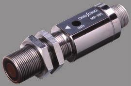
7 Magnetoelectric Rotation Detector MP-98/982 General-purpose/high speed detection model Electromagnetic Rotation Detector MP-8 series Low-to-medium speed Rotation Detectors External Gear Type This is a magnetic flux response type detector (the resistance value changes according to the magnetic flux) which internally has magnetic resistance elements, permanent magnets, a direct current amplifier, and a voltage regulator. It can detect over a wide range of rotation speed from ultra low speed to high, and outputs the results as a square waveform. Three models are provided; General-purpose type (MP-98), high speed detection type (MP-982), and acid-resistance and waterproof type (AP-98). Detection from nearly r/min Detection from low to high speeds ( to, r/min: MP-982 [-tooth gear]) Output as square waveform Compact, light weight, easy-to-mount 2 (2) Magnetoelectric Rotation Detector Acid-resistant, waterproof type Detection method Detection range Detection gear : detection using magnetic resistance elements : MP-98 Hz to 2 khz MP-982 Hz to khz : ferromagnet (tooth width: at least mm, module:. to ) Detection distance : see the graph at the right Power requirement : 2 ±2 VDC Power consumption : approx. ma (at 2 V, 2 ºC) Output waveform : square wave Lo: up to. V, Hi: ±. V Output impedance : approx. Ω Protective circuit : power source polarity, output short-circuit protection Operating temperature : - to + 7 ºC Storage temperature : -2 to +8 Withstand voltage : 2 VDC Vibration resistance (conduction) : 9 m/s 2 each in X, Y, Z direction Shock resistance (non-conduction) : 9 m/s 2 (three times each in the X, Y, Z directions) Connection method : see P.- : approx. 8g (including the two nuts used for fastening) Accessory : two nuts for fastening, instruction manual The AP-98 is a waterproof model that complies with the JIS C 92 Protective Class 7 (marking symbol: IPX7) requirements for the waterproof testing of electrical equipment and wiring materials. Ferromagnetic material ø Mounting flange 28 M Connector (R-RM) Positioning mark ø2 2-ø. Lock nut () 7 82 Ethylene propylene rubber sheath (approx..9 m) 2 8max MP-98 ø22 ø2 ø27 AP-98 Can be used for measurement in locations where nitric acid mist is in the atmosphere, or in environments where the detector may be submerged. Performs by non-contact detection Detection from ultra low to high speeds ( to 2, r/min [-tooth gear]) as square waves of the same amplitude Comes with a.9 m length acid-resistant cable attached Detection method : detection using magnetic resistance elements and magnetic gears Detection range : Hz to 2 khz Detection gear : ferromagnet (tooth width: at least mm, module: to ) Detection distance : see the graph at the right Power requirement : 2 ±2 VDC Module and detection distance Power consumption : approx. ma (at 2 V, 2 ºC) 2. Output waveform : square wave Lo; up to +. V, Hi; + ±. V Output impedance : approx. Ω Protective circuit : power source polarity, output. short-circuit protection Detection distance Operating temperature : (mm). - to 7 ºC (on the condition that it is within the atmosphere of IP-X7 {JIS C92}) Storage temperature : -2 to 8 ºC Withstand voltage : 2 VDC Vibration resistance (conduction) :.2 mm compound amplitude, Hz (for hour in each of the X, Y, and Z directions) Shock resistance (non-conduction) : 9 m/s 2 (three times each in the X and Y directions) Outer surface material : polycarbonate Connection method :.9 m length directly attached cable (other end: open) : approx. g (including a signal cable) Accessory : instruction manual Caution MP-98 and AP-98 have been designed for the purpose of detecting rotation speed. Please observe the following points when using these detectors. () A square wave with the same amplitude is output as the result of rotation measurement from low speed to high speed ( to 2, r/min: gear teeth per a gear). However, it does not necessarily mean that the high level is appeared at the peak of the gear, the low level at the valley. The starting points may not be the same when using several detectors for synchronous operation. (2) The output pulse width may be different depending on the rotating direction of a detection gear (CW direction / CCW direction). CW CCW. 2. Detection distance (mm). Detection distance (mm) (Example) (Example) Module and detection distance MP-98 Rotation speed: to 2, r/min ( P/R) Temperature: 2 C Peak Valley Detectable range. 2 Module (M) MP-982 Rotation speed: to, r/min ( P/R) Temperature: 2 C Detectable range Module (M) Rotating speed: to 2, r/min ( P/R) Temperature: 2 C Detectable range 2 Module (M) There are three models in the series, each with a different outer appearance: MP-8, MP-82 and MP-8. MP-8 (Base mount type) Blind cover (Exchangeable to a cable clamp) MP-82 (Dual-shaft type) Blind cover (Exchangeable to a cable clamp) 8 -ø7 MP-8 (Flange type) Blind cover (Exchangeable to a cable clamp) 82 Cable clamp (STP-7) (Suitable cable diameter: -.) (Standard cable: D2V or P-2) 8 Terminal box (M Crimp terminal) Color of lead wires Blue: signal Red: common -ø7 8 ø7 øh7 2 Cable clamp (STP-7) (Suitable cable diameter: -.) (Standard cable: D2V or P-2) ø8 ø7 øh7 -ø Cable clamp (STP-7) (Suitable cable diameter: -.) (Standard cable: D2V or P-2) Terminal box (M Crimp terminal) Color of lead wires Blue: signal Red: common ø7h7 øh øh7 ø Terminal box (M Crimp terminal) Color of lead wires Blue: signal Red: common 2 ø ø There are three models in the series, differentiated by their outer appearances. MP-8: base mount type MP-82: dual-shaft type MP-8: flange type Number of output pulses Model Number of Pulses (P/R) MP-8F, 82F MP-8G, 82G, 8G, 2, MP-8B, 82B, 8B * Models other than MP-8B are made-to-order products. Rotating speed range : to, r/min Output waveform Output voltage :. Vp-p or more DC resistance value : 77 ± Ω Inductance : 2 H typ. (at khz) Starting torque : 2 mn m or less Moment of inertia : approx.. kg cm 2 Allowable shaft load : radial 7N, thrust 98N Vibration resistance : 98 m/s 2 (for two hours in each of the X, Y, and Z directions) Shock resistance : 98 m/s 2 (for three times in each of X, Y, and Z directions) Operating temperature : - to 8 ºC : approx. 2 kg Connection method : M crimp terminal (JIS C 28.2-) (When using MP-8) See P. and P. Cable outlet : cable clamp (complies with IP-8) Surrounding magnetic field : up to. T Connector : connector output (MP-8) 2R2A <Related product: MP-87 (low impedance type)> Number of output pulses Model Number of Pulses (P/R) MP-87J 8 MP-87K 2 MP-87L MP-87M MP-87N 2 MP-87B <Related product: MP-87 (low impedance type)> Blind cover (Exchangeable to a cable clamp) 82 Cable clamp (STP-7) (Suitable cable diameter: -.) (Standard cable: D2V or P-2) Terminal box (M Crimp terminal) ø8 Specifications (different from MP-8/82/8) Rotation speed : to 2 r/min Output voltage :. Vp-p or more Direct current resistance value : ± Ω Inductance Color of lead wires Blue: signal Red: common -n7 ø7h7 øh7 Connector plugs 2P2B For attachment to the ( terminal box (with covers) :.2 H typ. (at khz) 97 2 ø ( Rotation Detectors Built-in Gear Type 2


 Maximum response speed : m/s (converted to circumferential speed of rotating shaft) Response")
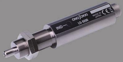
8 Rotation Detectors Photoelectric Type Optical Detector LG-92 Compact optical detector LG-92 is a reflective type photoelectric rotation detector using an optical fiber at the tip. Designed to be resistant against disturbance light using pulse modulation method for the light source emitting modulation. 2 (2) Mx øh7 Lock nut Connector (R - RM) 7 7 Photoelectric Rotation Detector LG-9 ø Detection from nearly r/min Compact and easy-to-use type optical detector A unified structure of light source, receiver and amplifier (weight: approx. g) Light emitting diode is used for light emitting element Easy positioning (visible light and operation indicator lighting function) Detection method Detecting distance : visible light photoelectric reflection method : recommended distance 2 to mm (when using a dedicated reflective mark 2 mm square) Maximum response speed : m/s (converted to circumferential speed of rotating shaft) Response delay time :. ms (light receiver conversion time) or less Light source : light emitting diode (red visible light) Light receiving element : phototransistor Power requirement : 2 ±2 VDC Current consumption : ma or less (at 2 V) Output waveform : rectangular wave; Hi... ±. V, Lo.... V or less Output impedance : kω or less Connection method : see P., Operating temperature : - to C Storage temperature : -2 to 8 C Conforming standard : CE marking : approx. g (including 2 nuts for fastening) Accessory : reflective mark (2 mm square, 2 sheets), mounting nut 2, instruction manual Compact model designed for the long-distance detection of visible light The LG-9 is a compact reflective type photoelectric rotation detector that can be positioned up to 2 mm away from the target object. (8) R R M Cable cord (ø):.9 m Measurement range of the LG-92 Distance from a shaft center L (mm) 8 2 L mm Setup distance 2 2 mm piece Rotation speed (r/min) Can be positioned at a distance of up to 2 mm away from the measurement object. The compact design enables it to be mounted in small spaces. Moreover, an L-shaped mounting fixture is provided. Visible light is used for easy positioning, and the built-in operating indicator light enables easy setup. The pulse lighting method ensures that the LG-9 is virtually unaffected by ambient light. Detection method : visible light photoelectric reflection method Detection distance : 7 to 2 mm (when using dedicated reflective mark of 2mm square) Object detected : reflective mark Maximum response speed : 2 m/s (when using the dedicated 2-mm-square reflective mark, affixing interval 8 mm) Response delay time :. ms (light receiver conversion time) or less Light source : light emitting diode (red visible light) Light receiving element : phototransistor Power requirement : 2 ± 2 VDC Current consumption : 8 ma or less (at 2 V) Output waveform : rectangular wave; Hi: + ±. V, Lo:. V or less (on condition that a load resistance is at kω at least.) Output impedance : kω or less Operating temperature : - to + ºC Storage temperature : -2 to +8 ºC Input/output connectors : directly attached cable with the other end open Cable length :.9 m : approx. g Accessory : reflective mark (2 mm square 2 sheets) mounting fixture, screw 2, instruction manual Photoelectric Rotation Detector FS-/2/, FG- Optical Fiber Sensor/Fiber Optic Sensor Amplifier Used with the combination of optical fiber sensor with an optical multimeter. Can be detected up to 9 mm away from the target. FG- 72 () FS-/2 FS- (.) (2) 2- (OFø.) () Rear view () Connector Application FS- L2 () Rotation measurement using photoelectric type non-contact rotation detector Affix a dedicated 2 mm square reflective mark to the shaft of the motor etc. and measure the rotation speed without contact by an optical fiber sensor. You can measure the target from a distance 2 mm max. (measurement distance from a detector to reflective marks: 7 to 2 mm). Reflective mark Motor Plug (2) (9) (ø.) (MAX ) ø LG-9 Photoelectric type rotation detector Panel mounting fixture (option) Rubber foot 8 (2) Panel cut dimension L 7 M (Effective screw length ) 2-M (lock nut) (OFø2) Caulking (ø, width ) (OFø2) SUS flexible tube L=2± 22 TM- Tachometer Optical fiber ø M8x Tip: SUS (Note) L can be changed (custom-made). AX-2N Power cable khz of maximum response frequency. Supports detection of high-speed rotation. Red visible light adopted, easy to detect an object that is difficult to adjust optical axis position, such as a thin shaft. Detection with high sensitivity to be able to detect even minimal changes in light amount and measures without reflective mark. (Unequal interval pulse which may be generated in detection without reflective mark can be divided into pulse.) Selectable gain/trigger level adjustment depending on a use application; manual adjustment using volume control button or auto adjustment using auto trigger. Provides two measurement distance settings; normal range or adjacent range. Detectable from adjacency to 9 mm max. FG- Fiber Optic Sensor Amplifier Detection method Specifications (FS-/2/) FS- FS-2 FS- Detection type Optical fiber reflection type Emitting port diameter at the tip of fiber ø mm ø 2 mm Fiber length (L) m 2 m Mounting nut M8 M Operating temperature range - to 2 - to 2 * Reflective mark (2 mm square 2 sheets) sheet included. * Fiber cable can be extended. Measurement of motor, fan, engine Rotation target Motor Fan Engine : detects amount of red visible light reflected light source; red visible light LED, light receiving element; phototransistor Detection distance : 7 to 9 mm (FS-/2), 2 to mm (FS-) Maximum response frequency : khz Output signal : analog; detects reflected light and outputs signal waveform in proportion to the light amount. output range: to V pulse; outputs pulse signal after the waveform of reflected light is shaped and converted to square wave. output voltage range; Lo level. V or less Hi level. V or more Load resistance Function * For more details of FS-/2/, FG-, please refer to the Product Brochure page of our website. : kω or more (analog, pulse) : gain; measurement distance can be adjusted by control knob or selection SW Threshold level; can be adjusted manually/automatically by control knob or selection SW. Frequency dividing; Selectable from to by the changeover switch. (Set within the range of to input pulses) Peak hold time constant; selectable from s/ s Display : for checking sensitivity; LED bar chart type monitor others; displays the status by LED indicator Connecting method : see P.- Power supply : to 2 VAC ( Hz/ Hz) Operating temperature : to ºC Operating humidity : to 8 RH (with no condensation) Conforming standard : compliant with CE marking : approx. kg Accessory : power cable (AC V), instruction manual, rubber foot ( pieces) set : stand (FG-), panel mounting fixture (FG-2) FG- Fiber optic sensor amplifier FS- Optical fiber sensor Rotation Measurement TM- series Tachometer FV- FV converter FFT/tracking measurement CF series FFT analyzer DS series Data station Rotation Detectors Photoelectric Type

9 Rotation Detectors Application Application Presence or absence detection of small parts FS- can project to a small part at a pinpoint with φ 2 mm of light emission. Presence or absence of a small part flowing on a production line can easily be detected by measuring reflected light amount and judging the level of it by the threshold function. FS- Red LED light FG- Product inspection of motors Non-contact measurement of rotation speed on small rotating shaft of mm diameter If there is unevenness on the rotating shaft or a black line, a periodic change occurs in the amount of reflected light of the optical fiber detector. Based on this periodic change, the rotation speed of the shaft is measured. The following example shows how to measure a thin rotation axis that is difficult to affix a reflective mark and a fan motor from that reflect light does not return straight. Applicable diameter of rotating shaft: mm or more Detection distance: approx. 2 to mm OK, LOWER, UPPER judgment on the production line available (comparator output from the FV-) MX- series Signal cable Large indicator Analog output BCD output Alarm Photoelectric type rotation detector (LG-92/9) Comparator output Personal computer TM- Multifunction digital tachometer RS-22C (parameter setting) UPPER SETTING LOWER SETTING Comparator output Pass/fail judgment PLC Rotary Encoder SP-ZA Ultra-compact type Output circuit 9 -MDepth ø28 ø8 ø2h8 øh ø.2 shielded cable L= Collector output 2.2 k Ω 2 7. to 2 V Economic type designed for OEM needs ø 8 outer diameter; ultra-compact, light weight model weighing only g 2-phase square wave + zero mark signal output Choice from pulse output types Number of output pulses :,,,, 2, 2,,,,,, 8, 9 P/R Output waveform : 2-phase square waveform+ zero mark (timing is optional) Output voltage : Hi Power supply voltage -2 % or more Lo. V or less Output method : collector load resistance; k Ω or more *Open collector: VDC, ma or less Adjacent error : ±/ P Power requirement : to 2 VDC ± %, ma * 2 VDC is also available only when the open collector is selected (option). Response frequency : khz Connection method : directly attached cable ( m) (other end: open) Maximum rotation speed : r/min Allowable shaft load : radial; 2 N thrust; N Starting torque : 2mN m Moment of inertia : g cm 2 Operating temperature : - to 7 ºC Storage temperature : -2 to 8 ºC Withstand humidity : 9 % (with no condensation) Protection class : IP Vibration resistance : 98 m/s 2 (for 2 hours each in directions) Shock resistance : 98 m/s 2 (for times each in directions, shaft; 98 m/s 2 ) : approx.. kg Rotation Detectors Rotary Encoder FG- Fiber optic sensor amplifier FV- High-speed F/V converter Recorder Output Fiber cable Comparator output Common FS- Optical fiber sensor Approx. 2 to mm DC motor Lower OK Upper Upper/lower limit judgment output Customer preparation * We have extensive variety of rotary encoders. Detailed brochures are prepared separately, so please visit out website. 7

 The fluorescent display tube greatly improves stability and readability. Compatible with our various detectors.")
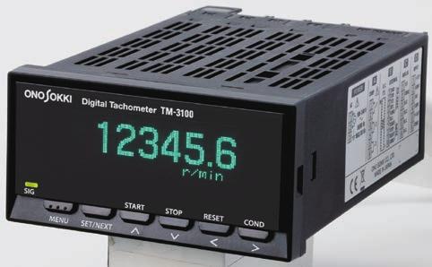
10 Rotation Display Unit Rotation Display Units General-purpose Digital Tachometer TM- series DIN standard size (9 8 mm) / for general-purpose TM- Display only TM-2 BCD output BCD mode setting screen TM- Analog output Analog output setting screen TM- Comparator output Up to types of judgment levels for upper and lower range High speed response with output update time of approx. ms Various output functions With BCD output of -digit display Basic model for measurement and display Wide measurement range from low to high speed (. Hz to khz) The fluorescent display tube greatly improves stability and readability. Compatible with our various detectors. With BCD output of -digit display Open collector output for direct connection with a PLC Output mode is selectable from normal or request. Output can be optionally changed to voltage output. Mode Normal mode : continuously outputs the print command every approx. ms. Request mode : Data is output for each request pulse. Output pulse can be switched between voltage and current. Improves update time ( ms) by using D/A conversion method. Output signal (voltage or current selectable) Output method : 2bit D/A conversion *Resolution decreases depending on the set value. Output voltage range : Selected from to V, to V, to V UPPER setup : -digit numeric input (The relay is ON when UPPER displayed value) LOWER setup : -digit numeric input (The relay is ON when LOWER displayed value.) OK setup : The relay is ON when UPPER or LOWER is OFF. ERROR setup : The relay is ON when any ERROR other than RS communication error occurs. Output format : -make contact output Three outputs : COMP, COMP2, and COMP Either of UPPER, LOWER, OK, or ERROR can be set to. Measurement mode Natural restoration mode : Automatic restoration when the rotation speed returns to within the set range Output signal BCD output Output form Outputs data and print command within a minimum of ms after receiving the request pulse. : -digit parallel output Output format : open collector Sync current : max. 2 ma Output withstand voltage : max. 2 V Output logic : positive logic Data refresh time : ms or less Input signal Request signal Input logic : negative logic (pulse width: µs or more) Operating edge : falling edge Input voltage : TTL Gate function : start, stop, reset Output current range : selectable from to 2 ma, to ma Load resistance Voltage output : kω or more Output current : Ω or less Linearity : ±. %/F.S. Analog output adjustment Voltage output : ± %/F.S. or more Current output : ± %/F.S. or more Zero drift : ±.%/F.S./ºC Span drift : ±. %/F.S./ºC Output refresh time : selectable from followings;, 2,,, 2, ms, s Comparator hysteresis : Sets hysteresis in judgment value at comparator return. Holding mode : Even if the rotation speed returns to within the setting range, it holds the state. Shot output function : Holds comparator output time for a certain time. OFF (shipping time), to 2 ms, set in increments of ms. COMP delay function : When the set value exceeds the setting time continuously for the set time or more, the comparator operates. to ms, set in increments of ms. Reset function : Resets in comparator holding mode. Maximum contact capacity : VDC V/A, 2 VAC/ A Output format : terminal block Output refresh time : approx. ms Depending on the application, you can choose the suitable model from four types: display only type, BCD output type, analog output type, or comparator output type. Various functions (common to all models) Display in various units is available by coefficient setting. Condition memory function Sudden deceleration follow-up function enables to follow up and display even at the time of a sudden stop. Calculation of the maximum value, minimum value, average value for each section Moving average function With auto zero function Pulse output World wide power supply ( to 2 VAC) Common specifications Input Output Display Input terminal : M, free terminal screw Input impedance : kω or more Input format : voltage or non-voltage Input amplification : AC or DC Compatible detectors: electromagnetic type/magneto-electric type/photoelectric type/rotary encoder/ proximity switch [Input amplification format specification] AC amplifier Signal waveform : sine or square wave Signal voltage : sine wave.2 to Vms square wave;. V to Vp-p Signal frequency : Hz to k Hz DC amplifier Signal waveform : rectangular waveform having a pulse width at µs or more Signal voltage : Hi level; + to + V, Lo level; - to + V Signal frequency :. Hz to khz Low pass filter : OFF/2 khz switchable <Pulse output> Output voltage : Hi level;. V or more Lo level;. V or less Output logic : negative Load resistance : kω or more Output terminal : M free terminal screw Display unit : fluorescent display tube (selectable from three-stage brightness, -digit display) Display refresh time : selectable from.2 s (factory setting),.s,.s,.s,.8s,. to s (in.s step). Display unit : select from the table below Character height : mm Number of decimal places to display : Select from OFF (none), st, 2nd, rd SIG indicator Error display Calculation Unit Rotation speed r/s, r/min, r/h Circumferential speed mm/s, m/s, mm/min, m/min Moving speed mm/s, m/s, mm/min, m/min, km/min, mm/h, m/h, km/h Period s, min No. of times (/s) /s, /min, /h Frequency Hz, khz Flow rate ml/s, ml/min, ml/h, l/s, l/min, l/h Transit time s, min EU/s, EU/min, EU/h : flashes synchronously with the input pulse : backup memory error, board error, input frequency error, display digit number error, memory full error, setting value error Calculation display : rotation speed, circumferential speed, moving speed, period, number of times (/s), frequency, flow rate, transit time Measurement method : period calculation method Measurement time : ms + period time Measurement accuracy : Displayed value (±. %) within ± count * The displayed value here indicates the count value excluding the decimal point. Auto zero function : This function sets the displayed value to if there is no pulse input during the set time. Select from OFF ( s),. s,. s, 2. s,. s,. s,. s,. s, 7. s, 8. s, 9. s,. s. Board Sudden deceleration follow-up function : When the input pulse suddenly decreases and not being input after approx. s or more, the display value automatically decreases and becomes after approx. seconds. Moving average function : Selectable from OFF (shipping time), 2,, 8,, 2,, 28 * Analog output of TM-/ performs moving average of the calculation value every ms and outputs it. Peak hold function : This function holds the peak values (maximum value, minimum value, average value) from measurement start to stop. Memory Panel condition memory : Memorizes kinds of measurement conditions (The setup conditions can be stored and recalled.) Power supply for detection Output voltage : 2 VDC ± % Maximum output current : ma General specifications Rated power : to 2 VAC ( Hz/ Hz) VA max. TM- ; to 9 VA TM-2 ; to 2 VA TM- ; to 2 VA TM- ; 2 to 2 VA * When all the cards (analog output, BCD output, comparator output) are installed: 2 to VA : VAC ( min) : MΩ or more (at VDC mega) Withstand voltage Insulation resistance Operating temperature : to ºC Storage temperature : - to ºC Operating humidity : to 8% RH (with no condensation) Storage humidity : to 8% RH (with no condensation) Outer dimensions : 9 (W) 8 (H) 8 (D) mm : approx. g Applicable standards CE marking : Low voltage Directive EN-:2 (2nd) Overvoltage category /pollution degree 2 EMC Directive EN2-:2 Embedded board type Accessory Instruction manual set : (spec edition, basic operation manual), panel mounting fixture set condenser power cable for V m (AX-2N) Function can be added by option board. By addition of TM-, further advanced measurement such as rotation fluctuation rate, section data can be performed besides RS-22C communication. board list TM-: DC power supply card TM-2: BCD output card, voltage output TM-22: BCD output card, open collector output TM-: Analog output card TM-: Comparator output card TM-: RS-22C card * Installation of optional boards after ordering a main body requires separate fee. Please contact your nearest distributor or Ono Sokki sales office nearby. Rotation Display Units General-purpose 8 9
11 AC COMP BCD EXTERNAL ANALOG INPUT RXD V/I +2 V 2 COM2 COM N.C. SIG N.C. COM 7 8 STOP N.C. P-OUT 9 N.C. COM2 ON/OFF T EXT-IN T2 SIG-IN T OUTPUT BCD-OUT RS-22C 2V / VA MAX FUSE 2A T NEXT POWER Digital Tachometer TM- Multifunction Digital Tachometer Rotation Display Units General-purpose Rear side panel connector terminal screw: M TM- TM TM-2 TM- TM- series output enlarged view TM- (display only) : POWER + D (INPUT) TM-2 (BCD output) : POWER + D (INPUT) + B (O.C.) TM- (analog output) : POWER + D (INPUT) + C (ANALOG) TM- (comparator output) : POWER + D (INPUT) + A (COMP) *By addition of board, function can be added. Application Measure the rotation speed of the shaft to display, output the measurement result to the printer or sequencer, also output to the comparator. In the following application, motor rotation is measured using MP-98 magnetoelectric rotation detector, TM-2 digital tachometer, and its optional functions. The rotation speed of a motor shaft is amplified by gears, and the rotation speed (r/min) and speed (m/min) of the rotator are calculated. The rotation speed of the shaft is measured by MP-98 magnetoelectric rotation detector, the calculation is made by TM-2 digital tachometer. Adding an option expands the range of output devices to. BCD output function (TM-2, TM-22): Printing, loading to the PLC Comparator function (TM-): Alarm can also be set. TM-2 + TM- Rotation display unit + comparator output card MX-7 series Signal cable 9 9 BCD cable (HDRA-EMA + to 7-) RQ- Digital printer.. Outer dimensions TM- series SIG MENU Measure, display, and record the shaft rotation speed and its fluctuation A rotation detector is attached to a gear on a rotating main shaft such as a stirrer, a mixer, a centrifugal separator, and the rotation speed of the shaft is measured and displayed. By using the analog output, you can record it on a recorder and check the rotation change. MP- Detection gear 9 Digital Tachometer TM- SET/NEXT START 9 STOP RESET COND 8 MX-7 series Signal cable MP-98 Electromagnetic detector 8 or more TM- Rotation display unit 99 or more +.8 Panel cut dimensions. 22 PANEL THICK MAX 2 () POWER A B C D -2 V TXD 2 CTS / Hz RTS MAX VA 2 COM2 N.C. START RESET COM2 ONO SOKKI CO., LTD. MADE IN JAPAN POWER A B C D AC COMP BCD EXTERNAL ANALOG INPUT RXD -2 V V/I +2 V 2 TXD 2 2 CTS 2 COM2 2 COM / Hz RTS COM2 N.C. SIG MAX VA 2 N.C. N.C. COM 7 START 8 STOP N.C. P -OUT 9 RESET COM 2 N.C. COM2 ONO SOKKI CO., LTD. MADE IN JAPAN RS-22C GATE Analog output AX-2N Power cable RS-22C GATE 2 () 2 TM- Recorder Customer preparation RESET COMP UPPER GOOD LOWER Rear view Digital Tachometer MENU SET TM- SELECT (9.) 72 MAX Panel cut dimension (.) Rotation measurement over a wide range from low to high speed (input frequency:. mhz to khz) Two sensors are used to display the rotation direction with phase difference pulse input Converts to arbitrary physical amount that is proportional to rotation speed by each channel independent coefficient correction function Built-in comparator function of upper and lower range in two stages 2ch calculation function displays rotation speed difference/rotation speed ratio/rolling reduction/draw/rotation change rate/direction of rotation. BCD, analog comparator, RS-22C are provided as standard for output function. Easy-to-install DIN standard size ( 72 mm) Two Displays: a main display section that indicates coefficient value and a sub display (2 steps) that indicates set items (comparator setting value/coefficient value/ 2ch measurement values) Applicable detector : MP series electromagnetic type / magneto electric type rotation detector, LG series photoelectric type rotation detector, RP series rotary encoder, roller encoder etc. Number of input ch : 2 Input amplifier type : AC/DC (switching type) Measurement method : periodic calculation method, gate calculation method (switching type) Measurement time :.2 s + period time (by periodic calculation method) Coefficient setting range :. to ch calculation function : difference <B-A>, ratio <(B/A) > change rate <(B-A/A) > Rotation direction measurement function : The direction of rotation is indicated by polarity display when 2-phase rotary encoder is used. Main display section : green 7-segment LED (character height: mm) display range ± (. to %) Sub display section (parameter setting display section) : LCD module Signal input section AC amplification section DC amplification section display character number characters 2 steps : input impedance kω or more (at khz) : signal waveform sine wave or square wave signal voltage range sine wave;.2 to + Vrms square wave;. to V P-P signal frequency range Hz to khz : signal waveform rectangular wave pulse of or more width signal voltage range Hi; to V, Lo; - to V signal frequency range. Hz to khz Comparator function : number of setting stages 2 setting range ± output item UPPER /GOOD/ LOWER output format semiconductor relay makeup contact ( VDC,. A) Analog output BCD output RS-22 communication Supply power for sensor : conversion method 2 bit, D / A method voltage range to ± V / F.S. (F.S. = Full Scale; can be set arbitrarily.) : positive/negative logic (switchable), -digit parallel output format open collector : baud rate 2, 8, 9 bps : VDC ±. 2 V (max ma) with the total value of A ch and B ch 2 VDC ±. V (max ma) for each channel of A ch and B ch : to 2 VAC (/ Hz) Power supply voltage Power consumption : VA or less Operating temperature : to C Storage temperature : - to C Operating (storage) humidity : max. 9 % (with no condensation) : approx.. kg Withstand voltage : VAC (between power supply and GND, min) Insulation resistance : MΩ or more ( VDC mega) Accessory : power cable, panel mounting fixture, foot stand, rubber foot, terminal socket ( pins), ( pins) 2, unit seal, instruction manual : BCD cable m (AA-87) RS-22C cable 2m (AX-22) Rotation Display Units Multifunction Type MP-98 Electromagnetic type rotation detector A Number of gears= AX-2N Power cable Sequencer Alarm Stirring machine MP- Detection gear B Number of gears=8 Comparator output Customer preparation 2 2
12 FFT Tachometer FT-2 Advanced Tachometer Rotation Display Units Advanced Type The FT-2 is a tachometer that performs frequency analysis by FFT calculation processing and measures rotation speed. Even when the rotating shaft is not accessible, it can measure from sound, vibration, etc. and supports various types of rotating objects such as steady rotation of a motor, acceleration / deceleration rotation of an engine. No need for reflective mark and special machining to install a detector Enables rotation measurement using sound and vibration easily. Machining of the rotating shaft is not required. Supports rotation speed change and acceleration/deceleration. (when selecting rotation acceleration/deceleration measurement mode) Rotation direction judgment function (FT-) Easy-to-read indication by fluorescent display tube With analog output, pulse output Input section Applicable sensors: FT-/8, IP-292/29/A/, VP-22/22, OM-2/, Constant Measurement section Measurement mode. Steady rotation measurement mode Application Current Line Drive sensors, (microphones, accelerometers) and so on. Frequency range : Hz, 2 khz, khz Rotation speed resolution : frequency range (Hz) 28 set pulse count 2. Rotation acceleration/deceleration measurement mode Frequency range : 2 Hz, Hz, 2 khz Rotation speed resolution : frequency range (Hz) set pulse count There may be some cases that the FT-2 cannot measure depending on the type of engine and motor, or the measurement range may change. Please confirm with the demonstration machine before order. Please contact the nearest distributors or our sales office for demonstration machines. Example of engine rotation speed measurement using cigar lighter socket sensor Connect to power outlet installed in an automobile or a construction machine. The ignition noise of the voltage output from the power outlet is detected and the rotation speed of engine can be measured by the FT-2. Compatible with battery 2 and 2 VDC. Advanced tachometer FT-2 Measurement accuracy : ±2 x rotating speed resolution (r/min) ± count (in both modes) *Measurement accuracy depends on frequency range. Rotation direction judgment : available when using FT- Averaging process : moving average processing Number of averaging times : OFF, 2,, 8, Filter function : Can be set arbitrarily Display section Display update time :. ±.2 second Measurement display range : to 999,999 r/min ( to, Hz) Output section Analog output : to V/ to F.S. to the displayed value Output update time : constant; ms or less (steady rotation active; measurement mode) 2 ms or less (rotation acceleration/deceleration mode) Sensor signal monitoring output : sensor signal output for monitoring (The output is selectable from analog or monitor output.) Comparator output Signal content Output voltage External interface : judgment of upper/lower limit, rotation direction judgment, OK judgment output method; semiconductor relay : pulse of frequency corresponding to the power spectrum extracted by FFT calculation : Lo V or less, Hi. V or more (without load) : RS-22C, external command input connector : saves kinds of setting conditions Condition memory General specifications Power requirement : to 2 VAC (/ Hz) Applicable standard : CE marking : approx..2 Kg Power consumption : 22 to 2 VA Operating temperature : to + C Storage temperature : - to + C Operating (storage) humidity : 2 to 8 % RH (with no condensation) Withstand voltage Insulation resistance Accessory : VAC (between power source and FG, min) : MΩ or more (between power source and FG, VDC) : power cable, panel mounting fixture, stand foot, rubber foot, connector, instruction manual pc. for each : analog output cable. m (FT-) {RPBM FT side) to BNC2(BNC)} Pulse output cable. m (FT-) {D-SUBPIN(FT side) to BNC2(BNC)} RS-22C cable 2 m (AX-22) Measurement example of rotation speed of DC motor incorporated in home electric appliances In this application, we measure the rotation of the electric toothbrush, which DC motor rotation is converted into brush vibration inside. The FT-2 measures the rotation speed by detecting the magnetic flux leakage from the DC motor incorporated in the toothbrush. Detects pulsation of magnetic flux leakage proportional to the number of poles of the DC motor from the completed product. With upper / lower limit comparator output for OK, LOWER, UPPER judgment on production line. Data management with RS-22C System can be upgraded at low price. FT-2 advanced tachometer FT- Rotation detector for DC motor Sensor specification Measurement target Detection method Major specifications Operating temperature range 2 R-PBM Signal cable m 72 (9.) 2 MAX Mounting thickness FT- 2± DC motor etc. (commutator type) Leakage magnetic flux detection Direct attached signal cable m With tip connector (R-PBM) *It is necessary to set the number of poles of the motor. - to ºC ø2 7 8 () Panel cut dimensions 8 +. FT-8 Cigar lighter socket sensor 9±. (.) 8 +. Cable length 2 m ø22. FT-8 Automobile, construction machine Voltage noise Plug in cigarette lighter socket. Cable length 2m With tip connector (C2) (BNC) to ºC (C2) BNC plug Rotation Display Units Advanced Type Advanced tachometer FT-2 Rotation detector for DC motor FT- RS-22C FT-8 Cigar lighter socket sensor Electric toothbrush Upper/lower limit judgment output (comparator function) PC (data management) 22 * Please contact us for more detail brochure of the FT-2. 2


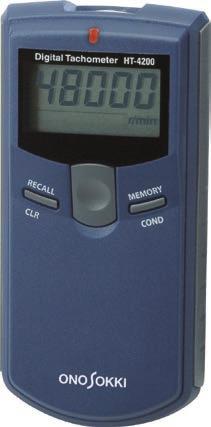
13 Handheld Tachometer Advanced Handheld Tachometer 2 Handheld Tachometer FT-72 Advanced Handheld Tachometer FT-72 FFT calculation method The FT-72 is a handy type tachometer that performs frequency analysis by FFT calculation processing and measures rotation speed. Can measure a wide range from steady motor rotation to acceleration/deceleration of engine rotation. Enables rotation measurement easily using sound and vibration. Machining of the rotating shaft is not required. Supports rotation speed change and acceleration/deceleration. Efficient for measuring engine rotation speed of completed vehicles etc. Various sensors can be used. Both analog and pulse outputs provided as standard. Used for recording rotation speed and as rotation synchronization signals. Large LCD with backlight. With averaging processing function. Measurement section Measurement object : DC motor, compressor, engine or general rotating body Calculation method : FFT calculation method Measurement time : within 2 ms Input frequency range :.7 Hz to 2 khz ( ranges switching) Measurement unit : r/min (rotation speed) Measurement accuracy (r/min) : ± 2 rotation speed resolution (r/min) ± count *Measurement accuracy depends on the frequency range. Rotation speed resolution (r/min): frequency range (Hz) number of set pulses frequency range; 2,, 2 (Hz) number of set pulses;.,,., etc. (P/R) ; resolution of FFT *It becomes coarse when the rotation speed is accelerating or decelerating. Filter function Averaging processing : Specifies the frequency range (rotation speed range) to be measured within the selected frequency range. : moving average processing number of averaging processing OFF, 2,, 8, Sensor amplifier sensitivity adjustment volume : Sensor amplifier sensitivity can be adjusted with the rotary type volume knob on the right side of the main unit. Detection section Compatible sensors : dedicated for engine rotation measurement OM-2/, VP-22/22, IP-292/29, IP-A/, FT-8 FT-+FT-, NP- series (with built-in preamplifier), MI series (microphone + preamplifier) :. V (-range switching) Input voltage level Input coupling : AC coupling Power supply for NP series accelerometer : constant current power supply (2. ±. ma) *Note on measurement: depending on the type of engine and measuring object, it may not detect properly. * Please visit our website for more detail brochure of the FT-72. Handheld Tachometer Display section LCD display Display update time Display resolution Measurement mode CNS (Constant) ACT (Active) : digits, LCD 7 segments, with backlight (character height.2 mm) :. ±.2 s : r/min : Used when the fluctuation of the rotation speed of the object to be measured is small (when measuring the rated rotation speed, etc.) : Used when the rotation speed of the object to be measured accelerates or decelerates. (However, when it changes suddenly, it may not measure correctly.) Output section [ANALOG] analog output (switch to analog output for monitor) Output content : Outputs to the rotation speed display value Voltage range : to V / to F.S. (F.S. is arbitrarily set.) Conversion method : bit D/A conversion method Linearity : ± % of F.S. Output update time : within 2 ms Temperature stability : ±.% of F.S. / C (ZERO & SPAN) Setting error : ±.% of F.S. (factory setting adjustment error, ZERO & SPAN) Load resistance : kω or more Output connector : mini jack (ø 2.) [ANALOG] analog output for monitor (switch to analog output) Output content : analog output for monitoring after waveform shaping of sensor pulse Load resistance : kω or more Output connector : mini jack (ø 2./commonly used with ANALOG output) [PULSE] output Signal content Output voltage Output frequency range Output update time Load resistance Output connector General specification Power supply Battery life Low battery display : Outputs frequency pulse of the power spectrum extracted by FFT processing : Lo. V or less, Hi. V or more (no load) :.7 Hz to 2 khz, equivalent to display rotation speed number of set pulses per rotation (P/R) : steady rotation mode (Constant); within ms rotation acceleration/deceleration mode (Active); within 2 ms : kω or more : mini jack (ø 2./commonly used with ANALOG output) : AAA battery or dedicated AC adapter (PB-79, sold separately) : approx. hours (When the backlight is off.) approx. hours (When the backlight is on.) (When alkaline battery is used, at 2 ºC, excluding when using the NP- series accelerometer* ) *: When using the NP- series accelerometer, consumption current increases by driving the constant current power, so we recommend using the dedicated AC adapter. : When the battery voltage becomes approx..2 V or less, the LOW mark is displayed. Operating temperature : to ºC Storage temperature : - to ºC Operating (storage) humidity : to 8% RH (with no condensation) Outer dimensions Compatible standard Accessory :. (W) 89. (H) 7. (D) mm : CE marking : approx. 2g (not including battery) : AAA battery, instruction manual (basic operation, function guide, measurement procedure) each, carrying case : relay cable for FT-;. m (FT-) output signal cable; 2m (AX-) dedicated AC adapter (PB-79) magnet stand (HT-22) stand jig (HT-2A) measurement tripod (LA-2 D) (Airy L manufactured by SLIK) Handheld Tachometer HT- Handheld Digital Tachometer HT- Contact/non-contact type multifunction type Extensive measurement from. r/min (low speed rotation) to r/min (high speed rotation). Memory function: up to 2 data of memory can be recorded. Both contact and non-contact measurement, line speed measurement is available with non-contact method. Both analog and pulse outputs provided as standard. Used for recording rotation speed and as rotation synchronization signals. Peak hold function installed: maximum value and minimum value during measurement can be displayed. Large LCD with backlight. Tripod, stand jig (option) mounting: can be fixed to a tripod etc. for continuous measurement. Detection method Detection distance Display section Measurement time Display update time Measurement unit Measurement accuracy Measurement function Peak hold function Memory function Over range function Rotation contact tip (KS-) + Contact adapter (HT-2) : red visible light photoelectric reflection method, contact method (attaching contact adapter) : 2 to mm : LCD, digits, with backlight (character height:.2 mm) : s+ input pulse, within period time (However, when it is r/min or less, it is about twice the period time) : approx. s : r/min, r/s (rotation speed), m/min (circumferential speed), ms (period), COUNT (integration count) Measurement range : Non-contact type Contact type r/min (Hi level) to to 2 r/min (Lo level). to.. to. r/s. to to. m/min. to to. COUNT to to ms. to to : display value* (±.2%) ± count *Display value is the count value excluding the decimal point. (Note) The measurement accuracy of circumferential speed depends on the rotation speed of the rotating body. The above measurement accuracy is for non-contact measurement. It does not include errors due to camera shake. Contact slippage and accuracy are added at the time of contact measurement. : maximum value (MAX), minimum value (MIN) : up to 2 data : over range (ERROR mark) is displayed when the measured value exceeds the measurement range. Rotation upper limit warning function : When the rotation speed exceeds a preset upper limit value, upper limit warning ( mark) is displayed. Circumferential speed calculation function : [non-contact type] circumferential speed is calculated with the preset diameter (mm) and the measured rotation speed. [contact type] circumferential ring KS-/2 is used. Integration count function : Performs integration pulse counting of input signal *Note: The display is updated every display update time. Period measurement function : Measures the period of input pulse (however, average value of input pulse if it is second or more) Rotation speed : non-contact type (with reflective mark), contact type (using KS-) Output section [analog output] Output voltage : to V / to F.S. (Full scale is arbitrarily set.) Conversion method : bit D/A conversion method Linearity : ± % F.S. Output update time : ms + input pulse within period time Temperature stability : ±. %/ F.S. / C (span & zero) Full scale setting error : ±. % /F.S. Load resistance : kω or more Output section [pulse output] Output voltage : Hi level. V or more (when detecting with reflective mark) Lo level. V or less Output logic : positive logic Load resistance : kω or more General specifications Power : AAA battery x or dedicated AC adapter (PB-79: sold separately) Battery life : approx. 2 hours (when the backlight is OFF) approx. 8 hours (when the backlight is ON) (When alkaline dry battery used, at 2 C) Low battery display : When the battery voltage becomes approx.. V or less, a LOW mark is displayed. Operating temperature : to C Storage temperature : - to C Operating (storage) humidity : to 8% RH (with no condensation) Outer dimensions : (w) 8. (H) 7. (D) mm (only main unit) (W) 27.2 (H) 7. (D) mm (contact adapter + rotation contact tip) Applicable standard : CE marking (excluding batteries) : approx.22g (only main unit) approx.282g (contact adapter+ rotation contact) Accessory : contact adapter (HT-2), rotation contact tip (KS-), circumferential ring (KS-2 for m/min), reflective mark (2mm square, 2 sheets), AAA battery, carrying case, instruction manual (function guide: Japanese/English, basic operation: Japanese/English) : pulse output cable; 2 m (AX-) dedicated AC adapter (PB-79) reflective mark; 2 mm square 2 sheet, sheet set (HT-) circumferential ring for mm/s (KS-) circumferential ring for m/min KS-2) rotation contact tip (KS-) contact adapter (HT-2) extension relay shaft for KS- (KS-7) stand jig (HT-2A) magnet stand (HT-22) measurement tripod (LA-2D) (Airy L manufactured by SLIK) 2 Handheld Tachometer Handheld Digital Tachometer


. A large-size display (character height. mm) is adopted to the compact, lightweight body.")
14 Handheld Tachometer Handheld Digital Tachometer 2 Handheld Tachometer HT-2/2/, HR-8 Handheld Digital Tachometer HT-2 Contact type / general purpose liquid crystal display With a low range setting that can measure from. r/min. A circumferential ring/rotation contact can be stored in a pocket of the main body. Won the Good Design Award Measurable from a low speed of. r/min to, r/min (circumferential speed:. to,. m/min). Large liquid crystal display on a compact, lightweight body (character height. mm). With memory function useful for checking measurement results. By replacing the contact tip with the attached circumferential ring, it can also measure circumferential speed. With a pocket to store the circumferential ring. Continues to display the latest measurement value for approx. seconds after power-off. Displays the timing of battery replacement. The -digit display enables wide-range measurement from to, r/min (when several reflective marks are used). A large-size display (character height. mm) is adopted to the compact, lightweight body. Memory function for easy confirmation of the measurement results Even it is shiny shaft its rotation can be measured by using the reflective marks provided as standard. Measurement can be performed over a wide range from to, r/min, in r/min unit (When one reflective mark is used.). Safe measurement available for being detectable from a position away from the measurement target (2 to mm). Continuously displays the latest measurement value for seconds after power off. Displays the timing of battery replacement. Method Display section : contact method : liquid crystal display, digits (character height. mm) Measurement unit : Lo range. r/min, Hi range r/min Display update time : second automatic repeat 2 seconds at Lo range ;. to. r/min 2 seconds at Hi range ; to r/min Measurement range and accuracy of rotation speed : Lo range. to 29.9 r/min; within ±. r/min 2. to 2. r/min; within ±.2 r/min Hi range to, r/min; within ± r/min Circumferential speed measurement range: KS-2 (provided) KS- (option) Lo range. to 2. m/min. to 2. mm/s Hi range. to. m/min to, mm/s It is an accuracy calibration at rotation speed. The unit of measurement can not be changed. When using KS-2, setting the measurement value to / will result in the value in m/min. Memory function : number of memories Data hold function : automatic power off seconds after the end of measurement Low battery display : LOW mark is displayed when the battery voltage drops below. V. HT-2 Non-contact type/general-purpose liquid crystal display Over range display : "ERROR" is displayed. Power requirement : AAA battery Battery life : approx. 2 hours (using alkaline dry batteries, at 2 C) Operating temperature : to C Storage temperature : - to C Operating (storage) humidity range : to 8% RH (with no condensation) Outer dimensions : (W) x 72 (H) x 8. (D) mm Applicable standard : CE marking : approx. g (without batteries) Accessory : contact tip for rotation measurement (KS-) x2 (One of them is stored in the main body), circumferential ring (KS-2 for m/min) (stored in the main body) AAA batteryx, instruction manual (English, Japanese) x each : circumferential ring for mm/s (KS-), circumferential ring for m/min (KS-2), rotation contact tip (KS-), extension shaft for KS- (KS-7), a carrying case (HT-) Affix a reflective mark to the rotating body of the measurement target object, and then aim the red visible light at the mark. By attaching multiple reflective marks, it is possible to measure from a lower speed. Won the Good Design Award Detection method : red visible light photoelectric reflection method Detection distance : 2 to mm Display : LCD, digits (character height ;. mm), fixed measurement unit (r/min) Display update time : second automatic repeat (however, 2 seconds when the circumferential speed is lower than /reflective marks r/min) Measurement range : measurement unit ;r/min Affixing of multiple reflective marks enables measurement of lower rotation speeds. Measurement range Number of reflective marks to, r/min to 2, r/min 2 to,7 r/min 8 to 2, r/min to 8, r/min to,2 r/min 8 Measurement accuracy (when one reflective mark is used) : to 2,99 r/min; within ± r/min 2, to 2,999 r/min; within ±2 r/min 2, to, r/min; within ± r/min Pulse number setting function : The number of reflective marks used can be specified in order to perform measurement from lower rotation speeds. setting values;, 2,,,, 8 P/R Memory function : data can be memorized. Data hold function : auto power off when seconds have elapsed after the end of measurement. Low battery display : LOW mark is displayed when the battery voltage drops below. V. Over range display : ERROR mark is displayed. Power source : AAA battery Battery life : approx. 2 hours (when using alkaline batteries at 2 ºC) Operating temperature : to ºC Storage temperature : - to + ºC Operating (storage) humidity : to 8 %RH (with no condensation) Outer dimensions : 2 (W) 29(H) 2. (D) mm Applicable standard : CE marking : approx. 9 g (not including batteries) Accessory : reflective marks sheet (2 mm square 2 marks), AAA battery, instruction manual (English, Japanese) each : reflective mark 2mm square 2; sheets set (HT-) carrying case (HT-), soft case (HT-) Handheld Tachometer HT-, HR-8 Handheld Digital Tachometer HT- Digital handheld tachometer The HT- is the model added two functions (opening and closing speed measurement and door opening and closing time measurement functions) to the HT- handheld digital tachometer. Door opening and closing speed measurement door opening and closing zebra tape Measurement section Measurement method : visible light reflection method Calculation method Measurement time Door opening and closing time measurement door opening and closing reflective mark : period calculation method : ms + input signal within one period time High-speed rotation measurement from to 999,99 r/min Built-in memory function, up to a maximum of 2 data can be saved to memory. Both analog and pulse outputs provided as standard. Used for recording rotation speeds, confirming detected waveforms and as rotation synchronization signals Built-in peak hold function: The maximum and minimum values can be displayed during measurement. Large LCD with backlight Measurement section Measurement target : rotating objects used in dentistry, texturizing machine, high-speed machine tools Note: target measurement objects must be magnetized. Display section Make-to-order product : LCD with backlight, -digit (character height:.2 mm) Measurement unit : r/min, r/s (rotation speed), m/min (circumferential speed, moving speed), ms (period, moving time, COUNT (integration count)) Measurement range : door opening and closing speed measurement ;. to m/min ( pulse interval mm) door opening closing time measurement ;. to ms rotation measurement mode; same as HT- (P.2) Measurement accuracy : display value (± %) ± count (Displayed value is a count value excluding decimal point.) Detection section Detection method : visible light photoelectric reflection method Detection distance : to 7 mm Light source : red light emitting diode Light receiving element : phototransistor Detection mark : reflective mark/ rotation, high precision reflection zebra tape Measurement function Peak hold function : maximum value (MAX), minimum value (MIN) Memory function : up to 2 data Over range function : Over range (ERROR mark) is displayed when a measured value exceeds the measurement range. Rotation upper limit warning function : When the rotation speed exceeds the preset upper limit value, displays upper limit warning ( mark). Circumferential speed calculation function : [non-contact type] Calculates the circumferential speed from the preset diameter value (mm) and HR-8 High rotation speed measurement model Measurement time : ms + input signal within periods Display update time: approx. s/approx.. s selectable Measurement unit : r/min (rotation speed) Rotation speed measurement range : to 999,99 r/min (range selectable) Measurement accuracy : display value ± (.2 %) ± count Peak hold function : maximum value (MAX), minimum value (MIN) Memory function : up to 2 data Over range display : When the measured value exceeds the measurement range, over range (ERROR mark) is displayed. Rotation upper limit warning function : When the rotation speed exceeds the preset upper limit value, upper limit warning ( mark) is displayed. Analog output section : output voltage; to V/ to F.S. (F.S.: arbitrarily set.)* output update time; ms + input pulse within period time Monitor output : for monitor analog output after waveform shaping of sensor pulse (before pulse waveform conversion) Pulse output : pulse output per pulse detection output voltage; Hi level. V or more, Lo level. V or less Power supply : AAA battery or a dedicated AC adapter (PB-79, sold separately) Battery life : approx. hours (when the backlight is OFF), approx. 8 hours (when the backlight is ON) (using alkaline batteries, at 2 C) the measured rotation speed. [contact type] Uses circumferential ring KS-/2 Integration count function: Measures the period of the input pulse. Period measurement function : Measures the period of input pulse. However, if it is less than second, average value of input pulse Rotation speed : non-contact type (with reflective mark), contact type (using KS-) Output section [analog output] Output voltage : to V/ to F.S. (Full scale is arbitrarily set.) Conversion method : bit D/A conversion method Linearity : ± %/F.S. Output update time : ms + input pulse within period time Temperature stability : ±.% / F.S./ C (span & zero) Full scale setting error : ±. % F.S. Load resistance : kω Output section [pulse output] Output voltage : Hi level. V or more (when detecting with reflective mark), Lo level. V or less Output logic : positive logic Load resistance : kω or more General specification : P.2 same as HT- Accessory : high precision reflective zebra tape ( m) x 2 rolls set Other accessories are same as P.2 HT-. : high precision reflective zebra tape ( m) x 2 rolls set Other optional items are same as P.2 HT-. Low battery display : LOW mark is displayed when the battery voltage drops below. V. Operating temperature : to C Storage temperature : - to C Operating (storage) humidity : to 8% RH (with no condensation) Outer dimensions : (W) 89. (H) 7. (D) mm Applicable standard : CE marking : approx. 2 g (main unit only, not including dry batteries) Accessory : AAA battery, adapter for tripod mounting (MI-), carrying case, instruction manual (basic operation, function explanation) each : output signal cable 2m (AX-) dedicated AC adapter (PB-79) Stand jig (HT-2A) Magnet stand (HT-22) Measurement tripod (LA-2D) (Airy L made by SLIK) Tripod mounting adapter (MI-) Detection section (sold separately) Dedicated detector : MP- Detection method : electromagnetic induction method DC resistance value : 2 to Ω (2 C) Connection cable (included) Operating temperature : to C Storage temperature : - to C Vibration and shock resistance : : m (both ends BNC connector included) 9. m/s 2 9 m/s 2 Outer dimensions : 7 x ø mm Applicable standard : CE marking : approx. g (detection section only) *Please refer to HT- for electrical specification of analog output. 27 Handheld Tachometer Handheld Digital Tachometer
 Measurement method : contact")


15 ON/OFF T EXT-IN T2 SIG-IN T OUTPUT BCD-OUT RS-22C 2 VA MAX FUSE 2A T NEXT POWER Related Products Elevator/Line Speedometer 28 Elevator Speedometer EC-2 Handheld Type Speedometer Analog output function Maximum value hold function Memory function Function of remaining battery level Auto power off function Averaging function Distance measurement function (option) Measurement method : contact type Measurement range : speed;. to 2,. (m/min) rotation speed; to 2, (r/min) distance (option); to ±999 (mm) *Distance measurement up to ± mm is available. However, measurement values more than ±999 mm is not guaranteed. Measurement accuracy : ± count (not including the error due to camera shake and slippage of contact part. Measurement time : ms Display Display update time : ms 2 M Depth8 : -digit, 7 segment, red LED in two-step display HIROSE Electric Co., LTD. Model:RM2BRB-PH 2-øH (8) s EC-2 EC-2 7 ø. Related Products Resolution :. (m/min/average number or more), (r/min, average number or more), (mm) Measurement unit : m/min, r/min, mm (option) Auto power off function : a delay of 8 seconds after last operation automatically turns the power off. Data hold function : data hold of each channel (CH, CH 2, Max value, each independent) Averaging function : to 2 times (optionally setup) Memory function : Up to measurement results can be stored in the main unit. Output section Analog output Pulse output : output content; instantaneous value (output after averaging processing) voltage range; to V/ to F.S. conversion method; -bit D/A conversion linearity; ± F.S. output update time; ms output connector; ø 2. mm pin-jack : output method; transistor output (open collector) withstand voltage; V current; 2 ma or less number of pulses; pulses / rotation logic; negative logic pulse width; approx.. to.2 µs output connector; ø 2. mm pin-jack Detection section Number of generated pulses : pulses/ rotation, slit reflection method Light source : infrared-emitting diode Light receiving element : photodiode Allowable shaft load : radial; kg, thrust; kg Bearing life : 2 7 r/min h (maximum load within the specification) General specification Power supply : AA battery x pieces Battery life : hours or more (continuous using at room temperature) Line Speedometer (Roller Encoder) RP-7 series Low to medium speed applications Number of pulses selectable from 2, 2, or 2 P/R Wide variety of output signal Totem pole (standard), Collector (option) Emitter (option), Open collector (option) Electrical specification Number of output : speed; 2, 2 P/R pulses length; 2 P/R Output waveform : 2-phase rectangular wave Duty ratio : ±2 % Phase difference : 9 ± Output voltage (when 2 VDC is supplied.) : Hi; V or more, Lo;. V or less Output method CE marking * Please visit our website for more details on RP-7 series. : Totem pole output (load resistance 7 Ω or more) s; RP-7 Emitter output RP-72 Collector output RP-7 Open collector output Power supply : 2 VDC± % ( ma or less) General specification Operating temperature : to + C (with no freezing, no condensation) Storage temperature : - to + C (with no freezing, no condensation) Operating humidity : to 9 % RH or less (with no freezing, no condensation) Protection class : IP (when RP-8/82 cable used) : applicable Current consumption : ma max. (power voltage. V) Operating temperature : to C Storage temperature : - to C Operating (storage) humidity : to 8 % (RH) (with no condensation) Outer dimensions : (W) 2 (L) 8 (D) mm CE marking Accessory : applicable : approx. 2 g (including batteries, not including the circumferential ring) : EC-922 external hold signal cable (.m) x set (2 pieces) EC-92 carrying case x piece hexagonal wrench (opposite side:.mm) x piece AA battery x pieces Instruction manual x piece : EC-22 Distance measurement function *If ordering after delivering the main unit, installation fee is required separately. KS- circumferential ring (wide type) ; mm KS- circumferential ring (narrow type) ;2 mm KS-8 circumferential ring (rubber coating wide type) ; mm KS- rotating contact tip EC-92 relay shaft for rotating contact tip EC-A external hold detection switch EC-92 signal cable ( m) EC-92 pulse output cable (2 m) EC-92 trigger unit cable (. m) AX- analog output cable (2 m) EC-922 external hold signal cable (. m) set (2 pieces) EC-92 carrying case piece * Please visit our website for more details on EC-2. : approx. g Accessory : instruction manual x connector (RM2BPE-S) x ; HIROSE Electric Co., LTD. Mechanical specification Speed range : to m/min *Speed measurement range depends on condition of measurement object. Measurement unit : 2 P/R. m/min 2 P/R. m/min 2 P/R mm Roller material : mandrel; aluminum rubber; polyurethane rubber baked on the roller surface (rigidity A9) Roller outer circumference : 2 mm Maximum allowable load : radial 2 N Starting torque : mn m Moment of inertia :. kg cm 2 Vibration resistance : 9. m/s 2 X/Y/Z each direction ( minutes each) to Hz sweep, 2 cycles Shock resistance : 9 m/s 2 X/Y/Z each for ± both directions (for directions) times for each (total 8 times) semisinusoidal wave, operating time ms Mounting hole (position) : ø mm x 2, 2 mm of interval : RP-7 Emitter output RP-72 Collector output RP-7 Open collector output RP-8 cable ( m) P.- RP-82 cable ( m) P.- Length Meter RV- Reversible Counter RESET COMP UPPER GOOD LOWER Rear view System Configuration Example RP-7 series Roller encoder Reversible Counter MENU SET RV- SELECT (9.) 72 Marker MAX 8 RP series Rotary encoder +. 8 Panel cut dimension Comparator Comparator BCD Analog RS-22C +. 8 () PLC Recorder PC Reversible counter designed to measure linear position, displacement, dimensions and so forth Easy-to-read large size LED ( mm) Wide range of external output functions (comparator, analog, BCD, and RS-22C communication) Four comparator setting values can be saved as conditions Applicable sensor : RP series (Rotary encoder) RP-7 series (Roller encoder) GS series (Linear gauge sensor) *Conversion cable required Display section : main display; red LED (mm), -digit and polarity ( to ±999999) sub display; LCD, characters x 2 lines, with backlight (yellow green) decimal point;,.,.,. (selectable) condition display; comparator condition; UPPER (red) / GOOD (green) / LOWER (red) Sensor input signal : single phase or 9 phase difference square wave voltage pulse (Hi... to V, Lo... to V) line receiver (conforms to RS-22A) input frequency range...dc to khz Power supply for sensor : selectable from ±.2 VDC (max ma) 2 ±. VDC (max 2 ma) External control signal : format of input signal; voltage input (Hi; to.2 V, Lo; to V), Non-voltage contact input types of input signal; reset, gate, offset, key protect Mode/function : multiplication; /2/ ratio compensation range;. to exponent value; /, /, /, / offset setting range; to ± Comparator function : setting range; to ± setting step; 2 steps output parameter; LOWER (Lower setting value calculated value) GOOD (Lower setting value < calculated value < upper setting value) UPPER (Upper setting value calculated value) output format; semiconductor relay (single make contact each) Max. contact capacity; VDC,. A update time: within ms BCD Input/Output Analog output : output signal (BCD, polarity, judgment, error, print command) open collector (withstand voltage: max. V) control signal (reset, hold) input format (voltage input); Hi; to.2 V, Lo; to V : output voltage range; to ± V/F.S. (F.S. can be set arbitrarily.) load resistance; kω or more linearity error; ±. % of F.S. calibration function; ZERO / FULL, 2 bit D/A method update time; within ms RS-22 communication : function; readout of data and parameter, setting of parameter baud rate; 2/8/9 bps Power requirement : to 2 VAC (/ Hz) Power consumption : VA or less Operating temperature : to + C Storage temperature : - to + C Operating/storage humidity : max. 9 % (with no condensation) : approx.. kg Withstand voltage : VAC (between power supply GND, min) Insulation resistance : MΩ or more (at VDC mega) Accessory : power cable x, panel mounting fixture x set, stand foot x set, rubber foot x set, terminal socket ( pins) x / ( pins) x 2, instruction manual x : BCD cable m (AA-87) RS-22C cable 2 m (AX-22) 29 Related Products Length Meter
. AC/DC input signal selectable. Frequency range can be optionally specified from Hz to khz.")

16 FUSE FUSE Related Products F-V Converter F/V F-V Converter FV- Frequency-to-Voltage/Frequency-to-Current Converter General-purpose type Withstand voltage: 2 VAC minute (chassis, primary power supply) Equipped power supply for detector as standard (2 VDC, ma). AC/DC input signal selectable. Frequency range can be optionally specified from Hz to khz. (standard: khz) (Fixed to the specified frequency. The setting cannot be changed.) Data output as current and voltage signals can be recorded to a pen recorder, and displayed to other indicators, etc. Compact monofunction type. Simple to use for smoothing the input frequency and indicating the average behavior or variation. PL POWER ON F/V CONVERTER SIG IND FV- 2 FREQUENCY OUTPUT VOLT OUTPUT CURR RESPONSE Conversion method Frequency range Response Panel mounting fixture (provided) () 99±.8 (.) : Constant width pulse integration method : khz (optionally available of specifying other frequency) : ms (Varies according to the frequency optionally specified.) Input frequency range : khz (Frequency in the range from Hz to khz can be specified as an option.) Input terminal : BNC (C2), terminal block (. M) Input voltage : AC input; sine wave ;.2 to Vrms square wave ;. to 7 Vp-p DC input; rectangular wave ; Hi + to + V Lo - to + V pulse width ; µs or more Input impedance : 8 kω or more (2 khz), kω ( khz) Output terminal : terminal block (. M) Output voltage : to V, load resistance kω or more ( to V/ to V/ to. V: available as an option) Output current : to 2 ma, load resistance Ω or less (setting also available in the range from to ma) Linearity : within ±.2 % of the maximum rated value Ripple :. % of the maximum rated value or mv or less (When the frequency input is % of the frequency range.) Detector power supply : 2 VDC ± % ma Power requirement : within AC 8 to AC V, to Hz (/2/2/22/2 VAC on request) Operating temperature range : to + ºC : approx. 2 kg Accessory : power cable for VAC (AX-2N, m) x flat-bladed screwdriver x panel mounting fixture x instruction manual x 8 (.) F/V F-V Converter FV- Frequency-to-Voltage/Frequency-to-Current Converter High response type Wide frequency range:.2 Hz to 2 khz High-speed response of every signal period Rotation direction judgment using two-phase signal input Rapid deceleration follow-up function Automatic center frequency follow-up function can analyze transient fluctuation component (option) Response : within period time of input Input voltage frequency +. µs : AC input signal voltage range;. to Vp-p DC input signal voltage range; Hi + to + V, Lo V or less Input frequency range :.2 Hz to 2 khz when fullscall mode output; Arbitrarily setting available in every Hz at the range from to 2, Hz. Arbitrarily setting available in every r/min at the range from to 2, r/min. Arbitrarily setting available in every m/min at the range from to 2, m/min. when in deviation output mode; Arbitrarily up to 2 khz of measurement frequency ± %, ± %, ± %, ±2 %, ± %, ± % or ± to 8, (can be set in every Hz, r/min, m/min) Input terminal : BNC (C2) or terminal block selectable Input format : single-phase, AC/DC/non-voltage selectable (+2 V pull-up for open collector devices) Two-phase signal with 9 phase difference (DC input only) Filter : OFF / 2 khz / 2 khz low-pass filter Analog output terminal signal : voltage output; to V (Full scale mode signal output, direction recognition function OFF) ± V (Full scale output mode, direction judgment function ON, deviation mode, automatic center frequency follow-up mode) Load resistance kω or more current output; to ma (at the time of shipment)/ to 2 ma Load resistance Ω or less Linearity : voltage output; DC: ±. % ( to 8 khz), ±.2 % ( to 2 khz) AC: ±.2 % ( to 8 khz), ±. % ( to 2 khz) current output; DC: ±.7 % ( to 8 khz), ±. % ( to 2 khz) AC: ±. % ( to 8 khz), ±2.8 % ( to 2 khz) Analog output low pass filter : OFF/ Hz/ Hz/ khz selectable Analog output terminal : BNC/C2 type (voltage output) or terminal block (phoenix contact: MC,/-STF-,8) (voltage output) selectable D/A resolution : -bit Display : fluorescent display tube (display range 9.8 mm. mm) Display unit : Hz, r/min, m/min, USER Power requirement for sensor : 2 VDC ± %, ma / VDC ± % ma Selectable by switch on the real panel. Operating power voltage range : VDC dedicated AC adapter ( to 2 VAC) provided as standard Operating temperature : to + ºC Storage temperature : - to ºC Operating humidity Storage humidity Accessory CE marking : to 8 % RH (with no condensation) : to 8 % RH (with no condensation) : approx. kg : dedicated AC adapter (AC adapter: PS-P22A cable: VM72-VM7 2m) x, instruction manual x, connector (MC./-STF-.8) (equipped with the main body) : Low Voltage Directive; 2/9/EC EN-:2 EMC Directive; 2/8/EC EN2-:2 Class A Table 2 : FV- (Automatic center frequency follow-up function) FV-2 (Comparator output function) FV- (Deviation scale change function) FV- (Open collector output function) FV- (Panel mounting fixture) Related Products F-V Converter Panel mounting fixture -M OUT ADJ Z O RE V U F L L INPUT Z O RE I U F L L.AT No. ONO SOKKI CO. LTD. MADE IN JAPAN.AT + () 7 INPUT OUTPUT V I ACV 2 2 SIG COM V 2 V HI LO HI LO 2 2 Panel cut dimension * Please visit our website for more details on FV-.
 Case Case PA-Z Used as an amplifier for electromagnetic detectors under electrically bad environment.")

17 Related Products Signal Amplifier Isolated Signal Amplifier Signal Amplifier 2 PA- Upper cover Grommet with seal (2) Isolated Signal Amplifier Signal Amplifier 2 (2) 7 (2) 7 Upper cover Grommet with seal (2) Case Case PA-Z Used as an amplifier for electromagnetic detectors under electrically bad environment. Converts the input signal into a high-voltage low-impedance signal to transmit the signal to remote locations accurately. 2 VDC power terminal for use with various sensors. Terminal block allowing easy wiring, sealed structure, a take-off vent for various plumbing and cabling methods. Isolated shielded type to allow installation on site. Noise-resistant. Input amplification Input impedance Can be used as an insulated amplifier by receiving square wave output from rotary encoder. Low impedance transmission for long distance available by wave-shaping. Supplies 2 VDC to DC power type RP series. The case is sealing structure which allows close mounting to the encoder. Isolated shielded type to allow installation on site. Noise-resistant. Number of input phases : three-phase Input resistance : 7 Ω Input waveform : rectangular waveform approx. % duty Input voltage : Hi; 8 to 2. V, Lo; to V Frequency range : to khz Output voltage : Hi; V±2 V ( kω load), Lo;. V or less ( kω load) Output resistance : collector resistance Ω Delay time : approx. 2 µs between input and output Operating power supply : VAC, approx. 2 VA Power source : 2 VDC,. A Operating temperature : - to ºC Storage temperature : - to 7 ºC : approx. kg Accessory : crimp terminal Terminal strip : applicable to JIS C 28.2 to crimp terminal al modification : : AC amplification : differential input: approx. 7 kω ( khz) single-ended input: approx. kω ( khz) Input waveform : sine wave or rectangular wave (with a duty of approx :) Input sensitivity : sine wave input ;. Vrms, rectangular wave input ;. Vp-p (max. allowable bias voltage: ± VDC) Frequency range : Hz to khz Operating voltage range : sine wave input ;. to Vrms rectangular wave input ;. to Vp-p Max. input apply voltage : sine wave; Vrms, rectangular wave; VDC Output waveform : rectangular waveform Voltage output : max. peak voltage (Vp-p) ; 2 ± V max. bias voltage (VBIAS);. V or less *The max. peak voltage and bias voltage between COM2 and OUT/2 without load while OUT2 and OUT is shortened. output impedance; approx. Ω Open collector output : collector maximum applied voltage; VDC collector maximum input current; ma *Between OUT2 and OUT; open Between OUT and COM2; collector maximum applied voltage, and collector maximum input current : 2 VDC ± %, ma max. Power source Operating temperature : - to ºC Storage temperature : -2 to 7 ºC Power requirement : VAC ± %, / Hz Power consumption : approx. 8 VA : approx. kg Accessory : crimp terminal x, fuse for 2/22V x, instruction manual x Terminal block : applicable to JIS C crimp terminal Item Open collector output Power voltage Input resistance Output resistance Modified specification Max. rating : VDC, ma AC V AC2 V AC22 V. kω 7 kω* 22 Ω (Output Z is not available.) Standard Collector output VAC 7 Ω Ω (three-phase) Please specify the item and specification to be modified when ordering. * Modification of input resistance to 7 Ω is required when RP-7 series with C specification (collector output type/ pull up resistance 7 Ω) is used. Coupling Selection Guide Rigid coupling of the electromagnetic type rotation detector with a device is required condition for the accurate transmission to both rotation and angle. If it has mounting errors including differences in shaft core and allowance in thrust direction, all of them are received as elastic deformation of the bearing, and it will cause the decrease of accuracy or damage. For stable and long use with rigid coupling, the shaft misalignment should be within / m. When you cannot make shaft centering with that accuracy, it is necessary to use flexible coupling which can accept the differences in shaft center and the allowance in thrust direction. There are various kinds of flexible couplings, such as one with high torsional rigidity, one suitable for general rotation speed measurement. It must be selected according to the application. Please perform the centering work as carefully as possible to prevent dynamic and static loads on the shaft beyond allowance. Recommended coupling shape/weight Fig. Rubber flex coupling RF- ø Coupling name Rub flex coupling RF- etc. Fig. Center flex coupling CF-A-2-2 Fig.2 Rubber Application MP-8B MP-2 Fig.2 Center flex coupling CF-A ø8 2 g g Features Relaxation of rubber impact elasticity Vibration damping Absorbs vibrations and shocks Does not occupy wide space in the axial direction Acceptable eccentricity, deflection angle [Note ] Rotation speed: 2 r/min Deviation:. mm Deflection angle: Rotation speed: r/min Deviation:. mm Deflection angle: Detaching method Attach the flange to the detector and the machine side. After setting to the dimensions specified in the centering rules, attach the rubber tire. Removable without moving system. Attach the flange hub and hub to the detector and the machine side, and attach the rubber body after centering. Remarks At high speed, expansion of the rubber due to centrifugal power causes a thrust power and it damages the detector. Drive side shaft diameter ø to ø 22 [Note 2] Drive side shaft diameter ø to ø 2 Manufacturer Nitta Chemical Industrial Products Co., Ltd. Miki Puli Co., Ltd. [Note ] Allowable eccentricity and deflection angle are the ranges in which the performance as a coupling can be guaranteed. However, please avoid installing in the way that the detector shaft exceeds the specified load even if it is within the permissible range. [Note 2] Customers should prepare hole machining on the drive shaft side. * For details of coupling, please contact each manufacturer. Related Products Coupling 2
Simplified Operations for TM-3100 Series Digital Tachometer
 Simplified Operations for TM-3100 Series Digital Tachometer The TM-3100 series Digital Tachometers has the most fundamental function in rotational measurement of four standard models (rotation speed display,
Select the rotation detector/rotation display unit that is optimal for your needs from the wide range of products that Ono Sokki is proud to offer.
 Digital Tachometers / Sensors and Peripherals Select the rotation detector/rotation display unit that is optimal for your needs from the wide range of products that Ono Sokki is proud to offer. Rotation
Digital Tachometer. TM-3100 series. Introducing a new digital tachometer with a clear display and ability to add functions separately and easily!
 Digital Tachometer TM-00 series Customize your tachometer with added function, which matches your own application. Highly compatible with personal computers and controllers. Provided with wide variety
TM-2100 Series. Digital Tachometer INSTRUCTION MANUAL ONO SOKKI CO., LTD. SIG SIG SIG SIG DIGITAL TACHOMETER TM-2130 DIGITAL TACHOMETER TM-2110
 TM-2100 Series Digital Tachometer INSTRUCTION MANUAL DIGITAL TACHOMETER TM-2110 DIGITAL TACHOMETER TM-2130 SIG SIG TM-2110 TM-2130 DIGITAL TACHOMETER TM-2120 DIGITAL TACHOMETER TM-2140 SIG SIG LOWER 1
Advanced Tachometer FT A digital tachometer that doesn't require. rotational pulse signals. FFT calculations performed by the device enable
 Advanced Tachometer A digital tachometer that doesn't require rotational pulse signals FFT calculations performed by the device enable measurement of rotational speed by sensing fluctuations in rotation-synchronized
Torque Station Pro TS-7700 System
 For Motor Torque Measurement Torque Station Pro TS-7700 System The Torque Station Pro is designed to automatically measure motor torque characteristics. The compact configuration includes a built-in brake
Operation. Displayed channel. Measuring range. Status indication/ remote control Key lock Measuring mode/ time constant. Scale.
 Electronics & Software Type 5080A... Multichannel Laboratory This universal laboratory charge amplifier can be used for force and torque measurements with piezoelectric dynamometers or force plates. Piezoelectric
Advanced Tachometer FT-2500
 // No rotational pulse signal is required for a measurement. The rotational speed is calculated from the frequency signal of light, magnetism, vibration, and sound. The is an advanced tachometer which
No mark Time-limit SPDT (1c) A Time-limit DPDT (2c) B Time-limit SPDT (1c), Instantaneous SPDT (1c) S DIN W48 H48mm.
 A Time-limit DPDT (2c) B Time-limit SPDT (1c), Instantaneous SPDT (1c) S DIN W48 H48mm.") Series Digital LCD Timer DIN W48 H48mm Features Power supply : 4-4VAC 5/6Hz, 4-4VDC universal Easy to switch Up/Down mode programmable output modes and timing ranges () Selectable function by front digital
Series Digital LCD Timer DIN W48 H48mm Features Power supply : 4-4VAC 5/6Hz, 4-4VDC universal Easy to switch Up/Down mode programmable output modes and timing ranges () Selectable function by front digital
NOVOTURN Multiturn Sensor non-contacting. Series RSM-2800
 NOVOTURN Multiturn Sensor non-contacting Series RSM-2800 Special features Non-contacting, magnetic Long life Electrical range 720 up to 5760 in 360 -steps available (2 to 16 turns) True-Power-On System:
High-speed Sub-micron Displacement Sensor with 40,000 Samples/sec. High Accuracy Inductive Gauging Technology
 High-speed, High-Accuracy Digital Displacement Inductive Sensor EX-V Series High-speed Sub-micron Displacement Sensor with 40,000 Samples/sec. High Accuracy Inductive Gauging Technology High-Performance
FT-2500 Advanced Tachometer Operation manual
 FT-2500 Advanced Tachometer Operation manual ONO SOKKI CO., LTD. Simplified Operation Manual for FT-2500 Advanced Tachometer FT-2500 Advanced Tachometer is a new rotational speed indicator that analyses
Absolute Rotary Encoder
 Absolute Rotary Encoder Use the Tough (Rated IP64 for Degree of Protection) Combined with a PLC or Cam Positioner for Optimum Control and Ease-of-Use Incorporates a sealed bearing, meeting IP64 for durability
Preset counters, electronic
 The Codix 716 / 717 can be used universally. These preset pulse, tachometers or preset timers with up to 2 presets can solve a wide variety of control and monitoring tasks in every application. With their
SPECIFICATIONS Digital Indicator 1. General
 SPECIFICATIS Digital Indicator 1. General The instrument is a digital indicator for the purpose of instrumentation, and suitable for the application in hopper, tank scale, and so on. 2. Specifications
NOVOHALL Rotary Sensor non-contacting. Series RSC-2800
 NOVOHALL Rotary Sensor non-contacting Series RSC-2800 Special features Non-contacting, magnetic technology Measuring range up to 360 Available with push-on coupling or marked shaft Simple mounting Protection
Incremental encoders With blind or through hollow shaft pulses per revolution programmable
 Features Size mm Precise optical sensing Output signal level programmable (TTL or HTL) Blind or through hollow shaft, ø8 15 mm Connection axial, radial or tangential Pulses per revolution 1...65536, programmable
Digital Multimeters R6451A/6452A. R6451A/6452A Digital Multimeters. 5 1/2 Digit DMM Series Enabling Dual Input and Display
 5 1/2 Digit DMM Series Enabling Dual Input and Display R6451A/6452A R6451A: General-Purpose Low-Price DMM with Standard Functions R6452A: Full-Functional DMM with Dual- Channel Input and Dual Display (Photo
TRD-J Series Incremental Encoders
 Series Incremental Encoders Features mm thick shaft and ø5 mm body Vibration and shock resistant metal slit plate durable at 1, P/R Operating voltage ranging from 4.75 to 3 VDC Totem-pole output facilitating
PD30CNB25xxPS. Photoelectrics, Background suppression reflective - PointSpot. Main features. Main functions. Description
 Photoelectrics, Background suppression reflective - PointSpot Main features Miniature sensor range The visible red PointSpot light makes alignment very easy Range: 250 mm Sensitivity adjustment by potentiometer
Though the size is compact, the measurement display uses 4 digit, 8 mm in letter height, red 7-segment LEDs. Letter height 8mm (0.
 SERIES Ultra-compact Digital Panel Controller CA Convenient s packed in a small body! Ultra-compact Large display Flexible scaling Conforming to EMC Directive Ultra-compact size of W 48 H 24 D 65.5 mm
HIGH VOLTAGE AND CURRENT CUT-OFF CAPACITY IN A COMPACT PACKAGE FEATURES
 HIGH VOLTAGE AND CURRENT CUT-OFF CAPACITY IN A COMPACT PACKAGE (60A type only) RELAYS A PC board type 80A Connector type 60A Screw terminal type A TM type 300A Connector type RoHS Directive compatibility
Absolute encoders - SSI
 with through hollow shaft Features Encoder multiturn / SSI Optical sensing method Resolution: singleturn 14 bit, multiturn 12 bit Compact design Cost-efficient mounting High reliability by self-diagnostics
LENORD. +BAUER... automates motion. GEL 2037 with heavy duty flange or tooth wheel adapter. Technical information Version General.
 GEL 2037 with heavy duty flange or tooth wheel adapter LENORD +BAUER... automates motion. Technical information Version 2014-07 General Multiturn absolute rotary encoders with a resolution of up to 25
Absolute encoders - SSI Solid shaft with clamping or synchro flange Optical multiturn encoders up to 14 bit ST / 16 bit MT
 Features Encoder multiturn / SSI Optical sensing method Resolution: max. singleturn 14 bit, multiturn 16 bit Clamping or synchro flange Electronic setting of zero point Counting direction input Available
Absolute Encoders - Singleturn
 The Sendix 5853 and Sendix 5873 singleturn encoders with SSI or BiSS interface and optical sensor technology can achieve a resolution of max. 7 bits. These encoders are also available with an optional
HIGH VOLTAGE AND CURRENT CUT-OFF CAPACITY IN A COMPACT PACKAGE
 HIGH VOLTAGE AND CURRENT CUT-OFF CAPACITY IN A COMPACT PACKAGE RELAYS (60A type only) 0A PC board type 0A TM type 60A Screw terminal type 80A Connector type 300A Connector type FEATURES. High-, high-current
Technical data. General specifications. Measurement range min max. 360
 Model Number Features Very small housing High climatic resistance 12 Bit singleturn Analog output Surge and reverse polarity protection Description This absolute rotary encoder with internal magnetic sampling
Incremental encoders Blind or through hollow shaft ø12 mm pulses per revolution
 Blind or through hollow shaft ø mm...5 pulses per revolution Features Encoder with blind or through hollow shaft ø mm Optical sensing method Max. 5 pulses per revolution Small profile depth Versatile mounting
HIGH VOLTAGE AND CURRENT CUT-OFF CAPACITY IN A COMPACT PACKAGE
 HIGH VOLTAGE AND CURRENT CUT-OFF CAPACITY IN A COMPACT PACKAGE RELAYS (60A type only) A PC board type A TM type 60A Screw terminal type 80A Connector type 300A Connector type Compliance with RoHS Directive
IXARC Incremental Encoder UCD-IPT M100-PRD. Interface Programmable Incremental. Configuration Tool UBIFAST Configuration Tool (Version 1.6.
 IXARC Incremental Encoder UCD-IPT00-08192-M100-PRD Interface Interface Programmable Incremental Programming Functions PPR (1-16384), Output, Counting Direction Configuration Tool UBIFAST Configuration
Stepping Motor Station
 Stepping Motor Station PV-7300 System A single system can measure all seven of the characteristics important in a stepping motor, namely the -T characteristic, holding torque, detent torque, pull-in torque,
Absolute encoders - SSI Solid shaft with clamping or synchro flange Optical multiturn encoders up to 14 bit ST / 16 bit MT
 Features Encoder multiturn / SSI Optical sensing method Resolution: max. singleturn 14 bit, multiturn 16 bit Clamping or synchro flange Electronic setting of zero point Counting direction input Available
Optical encoder MEC22 HR
 Optical encoder MEC22 HR Description The MEC22 HR is a high resolution optical hollow shaft encoder that can be fixed quickly and easily on different sizes of motor shafts. The encoder provides two square
Absolute encoders - analog Blind hollow shaft ø12 mm Magnetic single- or multiturn encoders 12 bit ST / 16 bit MT
 Blind hollow shaft ø mm Magnetic single- or multiturn encoders bit ST / bit MT BMSH 8, BMMH 8 analog - MAGRES Features Encoder single- or multiturn / analog Magnetic sensing Resolution: singleturn bit,
Absolute Encoders Multiturn
 The Sendix F36 multiturn with the patented Intelligent Scan Technology is an optical multiturn encoder in miniature format, without gears and with 00% insensitivity to magnetic fields. With a size of just
Absolute encoders - SSI Shaft with clamping or synchro flange Optical multiturn encoders 14 bit ST / 12 bit MT
 Features Encoder multiturn / SSI Optical sensing Resolution: singleturn 14 bit, multiturn 12 bit Clamping or synchro flange Electronic setting of zero point Counting direction input Suitable for high positive,
NPN PNP NPN PNP NPN PNP
 Cam Positioner Low-Cost, High-Performance Electronic Cam Switch for Use with OMRON E6F Rotary Encoder Control outputs can be programmed to turn ON/OFF in 1 units of rotary encoder shaft rotation Handles
ELECTRONIC COUNTER (with pre-scaling function) UL File No.: E C-UL File No.: E122222
 UL File No.: E C-UL File No.: E122222") EECTRIC (with pre-scaling function) C-S Counters C-S -digit type -digit type pin type type U File No.: E C-U File No.: E Features. Bright and Easy-to-Read Display A brand new bright -color backlight CD
EECTRIC (with pre-scaling function) C-S Counters C-S -digit type -digit type pin type type U File No.: E C-U File No.: E Features. Bright and Easy-to-Read Display A brand new bright -color backlight CD
XXXX e. X d.. X X X a
 The Heavy Duty incremental encoder type 0H boasts a high degree of ruggedness in a very compact design. Its special construction makes it perfect for all applications in very harsh environments. / RoHS
BS-3520 Digital Indicator
 BS-3520 Digital Indicator The Better Way for Weighing & easurements Table of Contents. Introduction...3 - Trait... 3-2 Warning... 4 2. Specification...5 3. External Size...6 4. Description on Front Panel...7
Integrated servo motor
 R88E-AECT@, R88S-EAD@ Integrated servo motor Motor and drive integrated for space optimization Wide range of motors from 2.55 Nm to 25 Nm 3000 rpm rated speed Peak torque 300% of rated torque IP65 protection
LED Collimated Beam Sensor LA-300 SERIES. LED collimated beam type which is as accurate as a laser sensor, but much safer.
 99 PHOTO PHOTO LED Beam Sensor - SERIES Related Information General terms and conditions... P.1 Sensor selection guide...p.11~ / P.~ CA... P.79 ~ General precautions... P.7 Conforming to EMC Directive
Incremental encoders With blind or through hollow shaft pulses per revolution programmable
 Features Size ø58 mm Precise optical sensing Output signal level programmable (TTL or HTL) Blind or through hollow shaft, ø8 15 mm Connection axial, radial or tangential Pulses per revolution 1...65536,
Technical data. General specifications. Linearity error ± 0.1 Electrical specifications Operating voltage U B
 Model Number SYNCHRON SERIELLES INTERFACE Features Very small housing Up to 32 Bit multiturn SSI interface Free of wear magnetic sampling High resolution and accuracy Description The ENA36IL series are
LENORD. +BAUER... automates motion. Magnetic absolute rotary encoder GEL 2037 with heavy duty flange or tooth wheel adapter
 Magnetic absolute rotary encoder GEL 2037 with heavy duty flange or tooth wheel adapter LENORD +BAUER... automates motion. Technical information Version 01.12 General Multiturn absolute rotary encoders
Inductive Proximity Sensor
 Inductive Proximity Sensor Linear Proximity Sensor with High-accuracy Resolution Resolution is 0.05% of the maximum sensing distance. The model with a sensing distance of 1.2 mm ensures a resolution of
Absolute encoders - SSI Solid shaft with clamping or synchro flange Optical multiturn encoders 18 bit ST / 12 bit MT
 Features High resolution encoder multiturn / SSI Optical sensing method Resolution: singleturn 18 bit, multiturn 12 bit Electronic setting of zero point Counting direction input Available with additional
Motor Encoders. With Motor encoders Series M - Optimal control of motor feedback -
 Motor Encoders With Motor encoders Series M - Optimal control of motor feedback - Hengstler supplies the new high-performance motor encoder series M for use with brushless servo motors and stepper motors.
LCSeries. Non-contact Speedometers SPEEDOMETER
 SPEEDOMETER Non-contact Speedometers LCSeries The LC-series is on-vehicle type of non-contact, non-marking speed measurement system with high accuracy. High-speed tests up to a maximum 320 km/h can be
Featuring a 100 μs sampling period and ±0.1% linearity
 484 laser displacement sensor series Featuring a 100 μs sampling period and ±0.1% linearity Seven types of sensor heads for various applications are available Sensor heads feature IP67 level water-resistance
True RMS Bench Multimeter 5492B
 Data Sheet True RMS Bench Multimeter 5492B True RMS Bench Multimeter The B&K Precision model 5492B is a versatile 5½-digit, 120,000-count bench multimeter suitable for applications in education, service
NOVOHALL Rotary Sensor non-contacting. Series RSC2800 digital SSI, SPI, Incremental
 NOVOHALL Rotary Sensor non-contacting Series RSC2800 digital SSI, SPI, Incremental The RSC 2800 sensor utilizes a contactless magnetic measurement technology to determine the measured angle. Unlike conventional
Rotary Measurement Technology Absolute Encoders, Multiturn
 Mechanical drive Safety-LockTM High rotational speed -40 to 90 C IP Temperature High IP High shaft load capacity Shock/ vibration resistant Magnetic field proof Short-circuit proof Reverse polarity protection
Wide-band Models from DC to 100 MHz
 CLAMP ON PROBE 327 series AC/DC CURRENT SENSOR CT686 series 99 Washington Street Melrose, MA 2176 Phone 781-665-14 Toll Free 1-8-517-8431 Visit us at www.testequipmentdepot.com Wide-band Models from DC
MODEL: 47LPA. [2] ALARM OUTPUT 0: None 1: N.O. relay contact, 4 points 2: SPDT relay contact, 2 points. Digital Panel Meters 47 Series
![MODEL: 47LPA. [2] ALARM OUTPUT 0: None 1: N.O. relay contact, 4 points 2: SPDT relay contact, 2 points. Digital Panel Meters 47 Series](/thumbs/96/126854447.jpg "MODEL: 47LPA. [2] ALARM OUTPUT 0: None 1: N.O. relay contact, 4 points 2: SPDT relay contact, 2 points. Digital Panel Meters 47 Series") Digital Panel Meters 47 Series FREQUENCY INPUT DIGITAL PANEL METER (4½ digit, LED display type) Functions & Features 4 ½ digit digital panel meter 1/8 DIN size Accepts a pulse train input to measure rotation
Digital Panel Meters 47 Series FREQUENCY INPUT DIGITAL PANEL METER (4½ digit, LED display type) Functions & Features 4 ½ digit digital panel meter 1/8 DIN size Accepts a pulse train input to measure rotation
Absolute Encoders Multiturn
 Absolute Encoders Multiturn Functional Safety, optical The absolute multiturn encoders Sendix 5863 SIL and 5883 SIL are perfectly suited for use in safety-related applications up to SIL3 according to DIN
LED Collimated Beam Sensor LA-300 SERIES. LED collimated beam type which is as accurate as a laser sensor, but much safer.
 99 PHOTO PHOTO LED Beam Sensor - SERIES Related Information General terms and conditions... P.1 Sensor selection guide...p.11~ / P.~ CA... P.79 ~ General precautions... P.7 Conforming to EMC Directive
Absolute Encoders - Singleturn
 The Sendix 5 and Sendix 7 singleturn encoders with SSI or BiSS-C interface and optical sensor technology can achieve a resolution of max. 7 bits. These encoders are also available with an optional SinCos
Wide-band Models from DC to 100 MHz
 CLAMP SENSOR Wide-band Models from DC to 1 MHz 3273-5 - 3276 CLAMP ON PROBES http://www.hioki.co.jp/ HIOKI company overview, new products, environmental considerations and other information are available
PM 6669 High-Precision Frequency Counter Specifications
 PM 6669 High-Precision Frequency Counter Specifications Product Home Features Specifications Models, Options & Accessories Measuring functions Definitions Input specifications Auxiliary functions TimeBase
Magnetic Encoder MEM 22
 Description The MEM 22 is a magnetic incremental encoder. He is a reliable low cost hollow shaft encoder that can be fixed quickly and easily on different sizes of motor shafts. The encoder MEM22 is designed
High-precision portable RESISTANCE METER
 8 High-precision portable RESISTANCE METER measures from µω to MΩ Features High-precision specs in a portable package(high accuracy of 0.02% rdg.) Design is ideal for maintenance and testing/measurement
Advanced Tachometer FT-2500
 // No rotational pulse signal is required for a measurement. The rotational speed is calculated from the frequency signal of light, magnetism, vibration, and sound. The is an advanced tachometer which
General Specifications
 General Specifications GS 77J01Q08-01E Model VJQ8 Pulse to Analog Converter (Multi-function) (Isolated Single-output and Isolated Dual-output Types) General This plug-in type pulse to analog converter
Technical data. General specifications. Linearity error ± 0.1 Functional safety related parameters MTTF d 700 a at 40 C Mission Time (T M ) L 10
 L 10") Model Number SYNCHRON SERIELLES INTERFACE Features Solid shaft SSI interface Up to Bit multiturn Free of wear magnetic sampling High resolution and accuracy Additionally push buttons for preset function
Model Number SYNCHRON SERIELLES INTERFACE Features Solid shaft SSI interface Up to Bit multiturn Free of wear magnetic sampling High resolution and accuracy Additionally push buttons for preset function
Select datum Page backward in. parameter list
 HEIDENHAIN Working with the measured value display unit ND Actual value and input display (7-segment LED, 9 decades and sign) Select datum Page backward in parameter list Confirm entry value Set display
1. BP4620 SPECIFICATIONS
 1. SPECIFICATIONS 1. SPECIFICATIONS 1-1 1.1 Specification Conditions 1-2 1.2 Output 1-3 1.3 Output Limiters 1-5 1.4 Signal Sources 1-6 1.5 Monitor Output 1-7 1.6 Measurement Functions 1-7 1.7 Sequence
USA series. Capable of long-distance measurement Built-in teaching function for simple operation and highlyaccurate
 series Ultrasonic displacement sensors (3m Type) Capable of long-distance measurement Built-in teaching function for simple operation and highlyaccurate measurement Integrated temperature sensor for stable
A new approach to static electricity countermeasures
 Advanced intelligent Sensors NEW ELECTROSTATIC SENSOR EF-SSERIES A new approach to static electricity countermeasures Measurement of surface potentials while a production line is running Phone: 8.894.42
E3S-CR62/67. Ideal for detecting transparent glass and plastic containers. Transparent bottle sensor. Features
 bottle sensor Ideal for detecting transparent glass and plastic containers Features Stable operation even if container interval is shortened for higher productivity. Stable detection of 5 mm gaps that
High Accuracy Eddy Current Type Displacement Sensor GP-A SERIES. Resolution 0.04 % F.S., Linearity ±0.5 % F.S., IP67g environment resistance
 13 High Accuracy Eddy Current Type Sensor SERIES Related Information General terms and conditions... F- Glossary of terms... P.139 Sensor selection guide... P.9~ General precautions... P.1 PHOTO PHOTO
NOVOHALL Rotary Sensor non-contacting. Series RSC2800 analog
 NOVOHALL Rotary Sensor non-contacting Series RSC2800 analog The RSC 2800 sensor utilizes a contactless magnetic measurement technology to determine the measured angle. Unlike conventional Hall sensors,
96M0374. Instruction Manual. Analog Sensor Controller. RD Series
 Instruction Manual Analog Sensor Controller RD Series 96M0374 Safety precautions This manual describes how to install the RD Series as well as its operating procedures and precautions. Please read this
RoHS. High shaft load capacity. Shock / vibration resistant
 Due to their sturdy bearing construction in Safety Lock Design, the Sendix 5000 and 5020 offer high resistance against vibration and installation errors. The rugged housing, high protection level of up
3239 (4-terminal Ω function) 3238 (Advanced model) 3237 (Economically priced) DIGITAL HiTESTER Field measuring instruments.
 3238 (Advanced model) 3237 (Economically priced) DIGITAL HiTESTER Field measuring instruments.") 2004 3239 (4-terminal Ω function) 3238 (Advanced model) 3237 (Economically priced) DIGITAL HiTESTER Field measuring instruments Outstanding performance for production lines with a sampling rate of 3.3
2004 3239 (4-terminal Ω function) 3238 (Advanced model) 3237 (Economically priced) DIGITAL HiTESTER Field measuring instruments Outstanding performance for production lines with a sampling rate of 3.3
TOS5300 SERIES Hipot Tester/Hipot Tester with Insulation Resistance Test
 A new standard for Hipot & Insulation resistance testing Applied to World-Wide input voltage TOS5301 TOS5300 TOS5302 TOS5300(ACW) TOS5301(ACW/DCW) TOS5302(ACW/IR) New low-cost standard model that provides
Heavy Duty Push-pull / RS422 / speed switch. RoHS 2/22. Magnetic field proof. XXXX e
 Sendix H00 (shaft) The Sendix encoder H00 is an extremely rugged available in 3 versions: encoder with or without speed switch and double encoder. Thanks to the special HD-Safety-Lock construction it is
True RMS Bench Multimeters 2831E and 5491B
 Data Sheet True RMS Bench Multimeters and True RMS Bench Multimeters with Dual Display The B&K Precision models and are versatile and dependable bench multimeters suitable for applications in education,
Technical data. General specifications V DC Power consumption P 0. 1 W Time delay before availability t v
 Model Number SYNCHRON SERIELLES INTERFACE Features Very small housing Up to 32 Bit multiturn SSI interface Free of wear magnetic sampling High resolution and accuracy Description The ENA36IL series are
DRTS 66 The new generation of advanced test equipments for Relays, Energy meters, Transducers and Power quality meters
 The new generation of advanced test equipments for Relays, Energy meters, Transducers and Power quality meters Testing all relay technologies: electromechanical, solid state, numerical and IEC61850 Manual
LENORD. +BAUER... automates motion. GEL 2351 with current or voltage interface. Technical information Version General. Features.
 GEL 2351 with current or voltage interface LENORD +BAUER... automates motion. Technical information Version 201-11 General Single turn absolute rotary encoder with a resolution of 16 bits Magneto-resistive
Absolute Encoders Singleturn
 The absolute singleturn encoders Sendix 5853 SIL and 5873 SIL are perfectly suited for use in safety-related applications up to SIL3 according to DIN EN ISO 6800-5- or PLe to DIN EN ISO 3849. The extra
Technical data. General specifications. Linearity error ± 0.1 Functional safety related parameters MTTF d 700 a at 40 C Mission Time (T M ) L 10
 L 10") Model Number SYNCHRON SERIELLES INTERFACE Features Recessed hollow shaft SSI interface Up to Bit multiturn Free of wear magnetic sampling High resolution and accuracy Additionally push buttons for preset
Model Number SYNCHRON SERIELLES INTERFACE Features Recessed hollow shaft SSI interface Up to Bit multiturn Free of wear magnetic sampling High resolution and accuracy Additionally push buttons for preset
High Accuracy Eddy Current Type Displacement Sensor GP-A SERIES. Resolution 0.04 % F.S., Linearity ±0.5 % F.S., IP67G environment resistance
 1 High Accuracy Eddy Current Type Sensor SERIES Related Information General terms and conditions... F-3 Glossary of terms... P.1 guide... P.11~ General precautions... P.19 PHOTO PHOTO MEASURE panasonic.net/id/pidsx/global
XXXX e. X d.. X X X a
 The Heavy uty incremental encoder type 0H boasts a high degree of ruggedness in a very compact design. Its special construction makes it perfect for all applications in very harsh environments. / RoHS
Supply voltage Output configuration Resolution (P/R) Model 12 to 24 VDC Complementary output 100, 200, 360, 500, or 600 E6F-CWZ5G 1,000
 Model 12 to 24 VDC Complementary output 100, 200, 360, 500, or 600 E6F-CWZ5G 1,000") Incremental 60-mm-dia. Rotary Encoder E6F-C The Strongest Shaft for Tough Jobs The strongest shaft of any OMRON Incremental Encoder (120 N in the radial direction and 50 N in the thrust direction). Water-
Incremental 60-mm-dia. Rotary Encoder E6F-C The Strongest Shaft for Tough Jobs The strongest shaft of any OMRON Incremental Encoder (120 N in the radial direction and 50 N in the thrust direction). Water-
6th digit. 5th digit. 4th digit. Code Specifications 3 20-bit absolute (standard) D 20-bit incremental (standard) Design Revision Order
 D 20-bit incremental (standard) Design Revision Order") Rotary s Model Designations - 3 D Series st+nd digits 3rd digit th digit th digit th digit 7th digit st+nd digits Rated Output th digit Serial Encoder 7th digit Options Code 3 3 W W 9 8 W 3.3 kw.8 kw 3.9
Rotary s Model Designations - 3 D Series st+nd digits 3rd digit th digit th digit th digit 7th digit st+nd digits Rated Output th digit Serial Encoder 7th digit Options Code 3 3 W W 9 8 W 3.3 kw.8 kw 3.9
 PWB encoders GmbH Am Goldberg 2 D-99817 Eisenach Germany Phone: +49 3691 72580-0 Fax: +49 3691 72580-29 info@pwb-encoders.com www.pwb-encoders.com 1 of 9 Description The ME22 is a reliable low cost optical
IDEAL INDUSTRIES, INC. TECHNICAL MANUAL MODEL: MODEL: Multimeter Service Information
 IDEAL INDUSTRIES, INC. TECHNICAL MANUAL MODEL: 61-340 MODEL: 61-342 Multimeter Service Information The Service Information provides the following information: Precautions and safety information Specifications
ICAM. Electronics & Software. Industrial Charge Amplifier for Applications in Manufacturing. Type 5073A...
 Electronics & Software ICAM Type 5073A... Industrial Charge Amplifier for Applications in Manufacturing The ICAM charge amplifier (Industrial Charge Amplifier Manufacturing) converts the piezoelectric
PE Electrical Machine / Power Electronics. Power Electronics Training System. ufeatures. } List of Experiments
 Electrical Machine / Power Electronics PE-5000 Power Electronics Training System The PE-5000 Power Electronics Training System consists of 28 experimental modules, a three-phase squirrel cage motor, load,
Technical data. General specifications V DC No-load supply current I 0. typ. 50 ma Power consumption P 0
 Model Number SYNCHRON SERIELLES INTERFACE Cable pull rotary encoder with SSI interface Features Solid yet lightweight plastic construction Compact, slim design (the shaft of the mounted rotary encoder
CIRCUIT-TEST ELECTRONICS
 USER'S MANUAL Sweep Function Generator with Counter SWF-8030 CIRCUIT-TEST ELECTRONICS www.circuittest.com TABLE OF CONTENTS SAFETY INFORMATION...page 3 INTRODUCTION... 4 SPECIFICATIONS... 5 FRONT PANEL
ALPHA 20 MULTIFUNCTION METER (ALPHA SERIES)
") Alpha Series www.sifamtinsley.co.uk Multifunction Meters Transducers & Isolators Temperature Controllers Converters & Recorders Digital Panel Meters Current Transformers Analogue Panel Meters Shunts ALPHA
Alpha Series www.sifamtinsley.co.uk Multifunction Meters Transducers & Isolators Temperature Controllers Converters & Recorders Digital Panel Meters Current Transformers Analogue Panel Meters Shunts ALPHA
BLuAC5 Brushless Universal Servo Amplifier
 BLuAC5 Brushless Universal Servo Amplifier Description The BLu Series servo drives provide compact, reliable solutions for a wide range of motion applications in a variety of industries. BLu Series drives
Application Alpha 20 Measures important electrical parameters in 3 phase 4 Wire and 3 phase 3 Wire Network & replaces the multiple analog panel meters
 Technical Data Sheet Alpha 20 Alpha 20 is a compact multifunction instrument which Measures important electrical parameters in 3 phase 4 Wire and 3 phase 3 Wire Network & replaces the multiple analog panel
Proximity Sensor Terminology
 The following descriptions refer to the European standard EN 60947-5-2. of 2007. The specifications given here are intended to be minimum performance values described by the standard. Alignment must not
VM-701B VIBRATION / DISPLACEMENT MONITOR MODULE Page 1 of 7
 Page 1 of 7 No entry if additional Model Code / Additional Spec. Code ( spec. code is not specified. ) VM-701B /PM /AL Phase Marker Function Analysis Function 0 Without 0 Without With Y With 1 (When /ALY
More Precision. mainsensor // Magneto-inductive displacement sensors
 More Precision mainsensor // Magneto-inductive displacement sensors 2 Magneto-inductive sensors for non-contact linear displacement measurement mainsensor - Selectable measuring ranges up to 55mm - Linear