QUICK SETUP GUIDE SECULIFE ESPRO
|
|
|
- Clinton Morgan
- 5 years ago
- Views:
Transcription


1 QUICK SETUP GUIDE SECULIFE ESPRO

 to measure various parameters relating to the routine service of Electrosurgical Generators.")
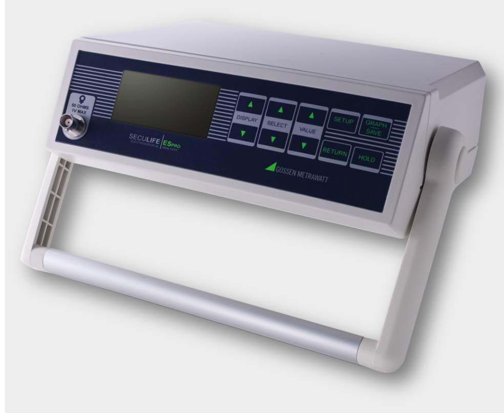
2 The SECULIFE ESPRO Electrosurgical Unit Analyzer is a high-accuracy True RMS RF Voltmeter designed to be used in the routine performance verification of Electrical Generators. The SECULIFE ESPRO offers a higher degree of accuracy than previously attainable with conventional Electrosurgical Unit Analyzer designs. The SECULIFE ESPRO has been designed to be used in conjunction with an external RF Current Transformer (Pearson Electronics Model 411 and 4100 recommended) and external precision load resistors (Vishay Dale NH-250 Precision 1% tolerance resistors recommended) to measure various parameters relating to the routine service of Electrosurgical Generators. The SECULIFE ESPRO is microprocessor based and utilizes a combination of unique hardware and software to provide accurate and reliable test results. SECULIFE ESPRO RF Current Transformer (Donut) Input Backlight LCD Graphical Display Swivel and Locking Handle 10 Light Touch Keys for Selecting Parameters and Settings RF Current Transformer (Donut) Input Backlight LCD Graphical Display Swivel and Locking Handle 10 Light Touch Keys for Selecting Parameters and Settings 1


3 Precision Load Resistance 5 Ω 5000 Ω Current Transformer Ratio from 0.1:1 or 1.1 2
 Connection of SECULIFE ESPRO with resistor, current transformer and DUT A connection between resistor, current transformer and DUT must be established before checking the RF output power")
 with the resistor, conduct it through the current transformer and plug it into the monopolar terminal of")
4 Verification of RF Output Power (monopolar) 1.) Connection of SECULIFE ESPRO with resistor, current transformer and DUT A connection between resistor, current transformer and DUT must be established before checking the RF output power (monopolar). The following cables must be connected to this end: - Connect the alligator clip (yellow) with the resistor, conduct it through the current transformer and plug it into the monopolar terminal of the DUT provide for this purpose (see yellow markings). - Insert the plug connector (blue) into the neutral electrode socket of the DUT. Establish a connection with the resistor by fixing two alligator at the resistor (see blue markings). - The current transformer is connected to the SECULIFE ESPRO with a BNC measuring cable (black markings). 3

.")
5 2.) Function test The RF output power is checked by comparing the value shown on the display of the DUT (here: 40 Watt) with the value issued by SECULIFE ESPRO (here: 42.6 Watt). Detail: DUT display Detail: SECULIFE ESPRO display 4
 Connection of SECULIFE ESPRO with DUT, resistor and current transformer The following connections must be established before measuring the RF output power (bipolar).")

6 Verification of RF output power (bipolar) 1.) Connection of SECULIFE ESPRO with DUT, resistor and current transformer The following connections must be established before measuring the RF output power (bipolar). - Connect the plug connector (blue) with the resistor, conduct it through the current transformer and plug it into the bipolar socket at the DUT - Insert the yellow clamp cable into the bipolar socket at the DUT and connect it with the resistor. - Establish a connection between the current transformer and SECULIFE ESPRO via BNC cable. Note: The blue cable, which is plugged into the neutral electrode socket of the DUT on one end and into the decade resistor on the other end, is used for approaching the trigger point. 5
 with the one")

7 2.) Function test Comparison of the value shown at the DUT display (here: 30 Watt) with the one issued by SECULIFE ESPRO (here: 30 Watt). Detail: DUT display Detail: SECULIFE ESPRO display 6

8 Graph Mode The GRAPH MODE allows the user to view the measured waveform in the display. The horizontal axis can be zoomed in to display higher frequency waveform components. The verticals axis is auto-scaling and cannot be adjusted. Any of the stored waveforms can be graphed. Additionally, if the unit is placed in the HOLD MODE, the user can adjust which portion of the waveform is being displayed. WARNING: Due to the limited number of pixels in the display, this should not be used as a calibrated reference, rather as a quick check of the waveform being measured. Use to enter the GRAPH MODE. Use to exit the GRAPH MODE. Selecting a Waveform: Use to select the waveform to be graphed, Ram or Location


9 Zooming Use to zoom the graph in and out. The Zoom Indicator is a bar that moves along the left side of the Graph Screen to indicate the Zoom level shown in the current viewing window. It adjusts from Fully Out (-) to Fully In (+). Saving To save the displayed waveform, use to enter the SAVE MODE. Use to select the desired storage location, then to save the waveform, or can be pressed to cancel the save function. Once the save is complete, the newly saved waveform will be displayed. 8


10 Error Messages Several error messages are provided to indicate invalid operating conditions. Any values that are over range will be displayed as dashes. When the input voltage rises above the range that is measurable by the system, the WARNING Input Overload message will be shown. WARNING: Although the input is protected from damage at these voltages, the user should immediately remove any input voltage when this message is shown. 9


11 GMC-I Messtechnik GmbH Südwestpark Nürnberg Germany TEL FAX
QUICK SETUP GUIDE SECULIFE HITAM
 QUICK SETUP GUIDE SECULIFE HITAM The measurement and testing of measuring equipment in the field of medical technology necessitates absolute reliability and a broad range of applications. The SECULIFE
QUICK SETUP GUIDE SECULIFE IP
 QUICK SETUP GUIDE SECULIFE IP The SECULIFE IP is capable of executing all measurements for testing the effectiveness of safety measures in electrical systems as required by IEC 60364-4 / VDE 0100-600,
SECULIFE SR PC Controllable Instrument for Measuring Safety-Relevant Characteristic Values of Electrical Devices /2.
 3-349-443-03 3/2.12 Applications Testing for the Electrical Safety of Electrical Medical Devices in Accordance with the German Medical Product Law (MPG) / MDD The test instrument is used for quick and
EE 210: CIRCUITS AND DEVICES
 EE 210: CIRCUITS AND DEVICES LAB #3: VOLTAGE AND CURRENT MEASUREMENTS This lab features a tutorial on the instrumentation that you will be using throughout the semester. More specifically, you will see
UCE-DSO210 DIGITAL OSCILLOSCOPE USER MANUAL. FATIH GENÇ UCORE ELECTRONICS REV1
 UCE-DSO210 DIGITAL OSCILLOSCOPE USER MANUAL FATIH GENÇ UCORE ELECTRONICS www.ucore-electronics.com 2017 - REV1 Contents 1. Introduction... 2 2. Turn on or turn off... 3 3. Oscilloscope Mode... 3 3.1. Display
METRAClip87 and 88 Clamp Multimeters
 3-349-795-03 1/7.14 Current and frequency measurement via clamp meter: METRAClip87: 1500 A AC TRMS and 1500 A DC METRAClip88: 2000 A AC TRMS and 3000 A DC Multimeter functions via connector sockets: V
ECE 2274 Lab 1 (Intro)
") ECE 2274 Lab 1 (Intro) Richard Dumene: Spring 2018 Revised: Richard Cooper: Spring 2018 Forward (DO NOT TURN IN) The purpose of this lab course is to familiarize you with high-end lab equipment, and train
ECE 2274 Lab 1 (Intro) Richard Dumene: Spring 2018 Revised: Richard Cooper: Spring 2018 Forward (DO NOT TURN IN) The purpose of this lab course is to familiarize you with high-end lab equipment, and train
Sonoma State University Department of Engineering Science Spring 2017
 EE 110 Introduction to Engineering & Laboratory Experience Saeid Rahimi, Ph.D. Lab 4 Introduction to AC Measurements (I) AC signals, Function Generators and Oscilloscopes Function Generator (AC) Battery
Activity P56: Transistor Lab 2 Current Gain: The NPN Emitter-Follower Amplifier (Power Output, Voltage Sensor)
") Activity P56: Transistor Lab 2 Current Gain: The NPN Emitter-Follower Amplifier (Power Output, Voltage Sensor) Concept DataStudio ScienceWorkshop (Mac) ScienceWorkshop (Win) Semiconductors P56 Emitter
Activity P56: Transistor Lab 2 Current Gain: The NPN Emitter-Follower Amplifier (Power Output, Voltage Sensor) Concept DataStudio ScienceWorkshop (Mac) ScienceWorkshop (Win) Semiconductors P56 Emitter
METRATESTER 5+ Tester for DIN VDE /6.15
 3-348-817-03 15/6.15 Applications Electrical safety testing of electrical equipment: per DIN VDE 0701-0702: 2008 by means of measurement of: Protective conductor resistance Insulation resistance Protective
Experiment P49: Transistor Lab 2 Current Gain: The NPN Emitter-Follower Amplifier (Power Amplifier, Voltage Sensor)
") PASCO scientific Vol. 2 Physics Lab Manual: P49-1 Experiment P49: Transistor Lab 2 Current Gain: The NPN Emitter-Follower Amplifier (Power Amplifier, Voltage Sensor) Concept Time SW Interface Macintosh
PASCO scientific Vol. 2 Physics Lab Manual: P49-1 Experiment P49: Transistor Lab 2 Current Gain: The NPN Emitter-Follower Amplifier (Power Amplifier, Voltage Sensor) Concept Time SW Interface Macintosh
QA-ES III Electrosurgical Analyzer
 QA-ES III Electrosurgical Analyzer Technical Data The QA-ES III Electrosurgical Analyzer simplifies testing to ensure the performance and safety of electrosurgical units. With generator output current
0.5% Accuracy Overload Fuse protection Test Clips/Direct insert jack for easy measurement TES Capacitance Meter
 TES-1500 Capacitance 0.5% Accuracy Overload Fuse protection Test Clips/Direct insert jack for easy measurement TES-2620 TRMS Multimeter TES-2700 TES-2712 LCR Multimeter 3-3/4 Digital LCD with bar-graph
UT232. Operating Manual. Digital Power Clamp Meter
 UT232 Operating Manual Digital Power Clamp Meter Model UT232 OPERATING MANUAL TABLE OF CONTENTS TITLE PAGE Overview Unpacking Inspection Safety Information Rules For Safe Operation International Electrical
How to Test OnFILTER Ground EMI Filters
 How to Test OnFILTER Ground EMI Filters Scope Ground EMI filters reduce high-frequency current in ground while preserving other grounding properties and meeting safety requirements This document outlines
LAB I. INTRODUCTION TO LAB EQUIPMENT
 LAB I. INTRODUCTION TO LAB EQUIPMENT 1. OBJECTIVE In this lab you will learn how to properly operate the basic bench equipment used for characterizing active devices: 1. Oscilloscope (Keysight DSOX 1102A),
Experiment P48: Transistor Lab 1 The NPN Transistor as a Digital Switch (Power Amplifier, Voltage Sensor)
") PASCO scientific Vol. 2 Physics Lab Manual: P48-1 Experiment P48: Transistor Lab 1 The NPN Transistor as a Digital Switch (Power Amplifier, Voltage Sensor) Concept Time SW Interface Macintosh file Windows
PASCO scientific Vol. 2 Physics Lab Manual: P48-1 Experiment P48: Transistor Lab 1 The NPN Transistor as a Digital Switch (Power Amplifier, Voltage Sensor) Concept Time SW Interface Macintosh file Windows
Operating Instructions / Voltage Tester per IEC with Phase and Polarity Tester and Phase Sequence Indicator
 Operating Instructions 3-349-298-15 3/11.09 METRAVOLT 7A Voltage Tester per IEC 61243-3 with Phase and Polarity Tester and Phase Sequence Indicator CAT IV GMC-I Messtechnik GmbH Südwestpark 15 90449 Nürnberg
HP 16533A 1-GSa/s and HP 16534A 2-GSa/s Digitizing Oscilloscope
 User s Reference Publication Number 16534-97009 February 1999 For Safety Information, Warranties, and Regulatory Information, see the pages behind the Index Copyright Hewlett-Packard Company 1991 1999
QA-ES III Electrosurgical Analyzer
 QA-ES III Electrosurgical Analyzer Technical Data The QA-ES III Electrosurgical Analyzer simplifies testing to ensure the performance and safety of electrosurgical units. With generator output current
UCE-DSO212 DIGITAL OSCILLOSCOPE USER MANUAL. UCORE ELECTRONICS
 UCE-DSO212 DIGITAL OSCILLOSCOPE USER MANUAL UCORE ELECTRONICS www.ucore-electronics.com 2017 Contents 1. Introduction... 2 2. Turn on or turn off... 3 3. Oscilloscope Mode... 4 3.1. Display Description...
Velleman Arbitrary Function Generator: Windows 7 by Mr. David Fritz
 Velleman Arbitrary Function Generator: Windows 7 by Mr. David Fritz You should already have the drivers installed Launch the scope control software. Start > Programs > Velleman > PcLab2000LT What if the
METRAClip85 and 86 Clamp Multimeters
 3-349-794-03 1/8.14 Current and frequency measurement via clamp meter: 600 A AC TRMS and 900 A DC (automatic or manual switching) Multimeter functions via connector sockets: V (AC TRMS and DC) up to 1000
BENCH METER Model>9803. Wavecom Instruments
 BENCH METER Model>9803 Wavecom Instruments 1 Basic Information This guide provides basic instructions for operating the Mastech M9803R Bench Digital Multimeter. The M9803R provides these features: Multiple
The Meter Structure The Figure 2-1 shows the Meter structure.
 P/N:110401104496X The Meter Structure The Figure 2-1 shows the Meter structure. 1. USB Terminals 2. LCD Display 3. Functional Buttons 4. Rotary Switch 5. Power adaptor Input Terminals 6. 10A Input Terminal
How to Setup and Use an Oscilloscope
 How to Setup and Use an Oscilloscope An oscilloscope is a device that is used to measure voltage with respect to time. Oscilloscopes are essential pieces of test equipment used in the development and testing
Module 1, Lesson 2 Introduction to electricity. Student. 45 minutes
 Module 1, Lesson 2 Introduction to electricity 45 minutes Student Purpose of this lesson Explanations of fundamental quantities of electrical circuits, including voltage, current and resistance. Use a
Calibration and Testing
 GHM GROUP CORPORATE GHM Messtechnik GmbH Schloßstr. 6 88453 Erolzheim GERMANY Phone +49 7354 937233-76 Fax +49 7354 937233-88 Features System Sources Measurement chain Strain gauge bridges Current signals
Model UT233 OPERATING MANUAL
 Model UT233 OPERATING MANUAL TABLE OF CONTENTS TITLE PAGE Overview Unpacking Inspection Safety Information Rules For Safe Operation International Electrical Symbols The Meter Structure A. The Meter Front
Laboratory Project 1a: Power-Indicator LED's
 2240 Laboratory Project 1a: Power-Indicator LED's Abstract-You will construct and test two LED power-indicator circuits for your breadboard in preparation for building the Electromyogram circuit in Lab
METRISO. Analog Insulation, Low Resistance and Voltage Measurement Instrument /9.14
 3-349-813-3 1/9.14 Insulation measurement per EN 61557-2/VDE 413, part 2 Test voltages: 5 V, 1 V, 25 V, 5 V and 1 V Analog display of measured values and limit values Intelligent filter precise and measurement-dependent
LAB I. INTRODUCTION TO LAB EQUIPMENT
 1. OBJECTIVE LAB I. INTRODUCTION TO LAB EQUIPMENT In this lab you will learn how to properly operate the oscilloscope Agilent MSO6032A, the Keithley Source Measure Unit (SMU) 2430, the function generator
Lab #1 Lab Introduction
 Cir cuit s 212 Lab Lab #1 Lab Introduction Special Information for this Lab s Report Because this is a one-week lab, please hand in your lab report for this lab at the beginning of next week s lab. The
Quick Start Guide for the PULSE PROFILING APPLICATION
 Quick Start Guide for the PULSE PROFILING APPLICATION MODEL LB480A Revision: Preliminary 02/05/09 1 1. Introduction This document provides information to install and quickly start using your PowerSensor+.
3 PHASE DIGITAL POWER CLAMP METER USERS MANUAL
 PHASE DIGITAL POWER CLAMP METER USERS MANUAL CONTENTS Safety Precautions - - - - - - - - - - - - - - - - - - - - - - - - - - - Safety Information - - - - - - - - - - - - - - - - - - - - - - - - - - - Safety
CABLE TESTER. Models CA7024, CA7026 & CA7028. Call toll free (800) or visit
 or visit") CABLE TESTER Models CA7024, CA7026 & CA7028 Call toll free (800) 537-0351 or visit www.allspec.com Hand-held LAN Cable Mapping and Troubleshooting Tester (Model CA7028) Hand-held Alphanumeric TDR (Time
CABLE TESTER Models CA7024, CA7026 & CA7028 Call toll free (800) 537-0351 or visit www.allspec.com Hand-held LAN Cable Mapping and Troubleshooting Tester (Model CA7028) Hand-held Alphanumeric TDR (Time
Experiment 15: Diode Lab Part 1
 Experiment 15: Diode Lab Part 1 Purpose Theory Overview EQUIPMENT NEEDED: Computer and Science Workshop Interface Power Amplifier (CI-6552A) (2) Voltage Sensor (CI-6503) AC/DC Electronics Lab Board (EM-8656)
ivu Series TG Image Sensor
 Quick Start Guide Introduction The ivu Series Image Sensor is used to monitor labels, parts, and packaging for type, size, orientation, shape, and location. The sensor has an integrated color touch screen
Lab 11: Circuits. Figure 1: A hydroelectric dam system.
 Description Lab 11: Circuits In this lab, you will study voltage, current, and resistance. You will learn the basics of designing circuits and you will explore how to find the total resistance of a circuit
WHALETEQ. ESU Neutral Electrodes Impedance Tester. Model: HFPA150. User Manual
 WHALETEQ ESU Neutral Electrodes Impedance Tester Model: HFPA150 User Manual Version2014-10-30 Hardware Version1.3.x 1. Introduction HFPA150 is a unique tester specifically designed for the testing of neutral
Experiment 8: An AC Circuit
 Experiment 8: An AC Circuit PART ONE: AC Voltages. Set up this circuit. Use R = 500 Ω, L = 5.0 mh and C =.01 μf. A signal generator built into the interface provides the emf to run the circuit from Output
Fluke 345. Power Quality Clamp Meter. The ideal meter for commissioning and troubleshooting modern electrical loads
 Fluke 345 Power Quality Clamp Meter Technical Data The ideal meter for commissioning and troubleshooting modern electrical loads With a bright color display to analyze the harmonic spectrum, a low-pass
JD723A/JD724B/JD726A Cable and Antenna Analyzers
 COMMUNICATIONS TEST & MEASUREMENT SOLUTIONS JD723A/JD724B/JD726A Cable and Antenna Analyzers Key Features Portable and lightweight handheld instrument. Built in wireless frequency bands as well as the
MODEL 9050 EXTENDED SPECIFICATIONS. 50ppm TRANSPORTABLE CALIBRATOR
 MODEL 9050 EXTENDED SPECIFICATIONS Ü 50ppm TRANSPORTABLE CALIBRATOR 9050A EXTENDED SPECIFICATIONS General Specifications TRANSMILLE LTD Warm Up Time Double the time since last used up to 20 minutes maximum
Experiment 13: LR Circuit
 012-05892A AC/DC Electronics Laboratory Experiment 13: LR Circuit Purpose Theory EQUIPMENT NEEDED: Computer and Science Workshop Interface Power Amplifier (CI-6552A) (2) Voltage Sensor (CI-6503) AC/DC
AME140 Lab #2 INTRODUCTION TO ELECTRONIC TEST EQUIPMENT AND BASIC ELECTRONICS MEASUREMENTS
 INTRODUCTION TO ELECTRONIC TEST EQUIPMENT AND BASIC ELECTRONICS MEASUREMENTS The purpose of this document is to guide students through a few simple activities to increase familiarity with basic electronics
On-Line Students Analog Discovery 2: Arbitrary Waveform Generator (AWG). Two channel oscilloscope
. Two channel oscilloscope") EET 150 Introduction to EET Lab Activity 5 Oscilloscope Introduction Required Parts, Software and Equipment Parts Figure 1, Figure 2, Figure 3 Component /Value Quantity Resistor 10 kω, ¼ Watt, 5% Tolerance
EET 150 Introduction to EET Lab Activity 5 Oscilloscope Introduction Required Parts, Software and Equipment Parts Figure 1, Figure 2, Figure 3 Component /Value Quantity Resistor 10 kω, ¼ Watt, 5% Tolerance
Low Value Impedance Measurement using the Voltage / Current Method
 Low Value Impedance Measurement using the Voltage / Current Method By Florian Hämmerle & Tobias Schuster 2017 Omicron Lab V2.2 Visit www.omicron-lab.com for more information. Contact support@omicron-lab.com
BME/ISE 3511 Laboratory One - Laboratory Equipment for Measurement. Introduction to biomedical electronic laboratory instrumentation and measurements.
 BME/ISE 3511 Laboratory One - Laboratory Equipment for Measurement Learning Objectives: Introduction to biomedical electronic laboratory instrumentation and measurements. Supplies and Components: Breadboard
MANUAL PCE-UT232
 www.pce-group-europe.com PCE- Deutschland Gmb H & Co. KG Tel: +49 029 03 976 99-0 Fax: +49 029 03 976 99-29 info@warensortiment.de www.warensortiment.de PCE Group Ibérica S.L. Tel: +34 967 543 548 Fax:
Appendix A: Laboratory Equipment Manual
 Appendix A: Laboratory Equipment Manual 1. Introduction: This appendix is a manual for equipment used in experiments 1-8. As a part of this series of laboratory exercises, students must acquire a minimum
Voltage Current and Resistance II
 Voltage Current and Resistance II Equipment: Capstone with 850 interface, analog DC voltmeter, analog DC ammeter, voltage sensor, RLC circuit board, 8 male to male banana leads 1 Purpose This is a continuation
Name: Resistors and Basic Resistive Circuits. Objective: To gain experience with data acquisition proto-boards physical resistors. Table of Contents:
 Objective: To gain experience with data acquisition proto-boards physical resistors Table of Contents: Name: Resistors and Basic Resistive Circuits Pre-Lab Assignment 1 Background 2 National Instruments
Table of Contents. Chapter 3. The 843-R Power Meter Unit.. 17
 Table of Contents Chapter 1. Introduction: How to Use This Manual... 3 Chapter 2. Quick Reference... 4 2.1 Getting Started... 4 2.2 Functions with No Sensor Connected... 5 2.3 Thermal Sensors... 8 2.4
DC Biased Impedance Measurements MOSFET
 DC Biased Impedance Measurements MOSFET By Florian Hämmerle, Steve Sandler & Tobias Schuster 2017 by OMICRON Lab V2.0 Visit www.omicron-lab.com for more information. Contact support@omicron-lab.com for
Multiple Instrument Station Module
 Multiple Instrument Station Module Digital Storage Oscilloscope Vertical Channels Sampling rate Bandwidth Coupling Input impedance Vertical sensitivity Vertical resolution Max. input voltage Horizontal
AVTECH TECHNICAL BRIEF 15 (TB15) A COMPARISON OF REVERSE RECOVERY MEASUREMENT SYSTEMS
 A COMPARISON OF REVERSE RECOVERY MEASUREMENT SYSTEMS") A V T E C H E L E C T R O S Y S T E M S L T D. N A N O S E C O N D W A V E F O R M E L E C T R O N I C S S I N C E 1 9 7 5 P.O. BOX 265 OGDENSBURG, NY U.S.A. 13669-0265 TEL: 888-670-8729 (USA & Canada)
A V T E C H E L E C T R O S Y S T E M S L T D. N A N O S E C O N D W A V E F O R M E L E C T R O N I C S S I N C E 1 9 7 5 P.O. BOX 265 OGDENSBURG, NY U.S.A. 13669-0265 TEL: 888-670-8729 (USA & Canada)
Understanding the Precision Antenna, Cable, and Power Measurements on the 3550 Radio Test System
 Application Note Understanding the Precision Antenna, Cable, and Power Measurements on the 3550 Radio Test System The Aeroflex 3550 Radio Test System now includes new methods for more accurately measuring
What tests should be done?
 Valleylab Force FX periodic testing Electrosurgery The passage of high frequency electrical current through tissue to create a desired clinical effect. 2/7/2009 1 What tests should be done? 1. Output tests
ESU-2000 Series Product Overview
 BC Group International Inc 3081 Elm Point Industrial Dr. St. Charles, MO 63301-4333 USA ESU-2000 Series Product Overview A Paradigm Shift In Electrosurgery Testing Technology and Capability Is Here Your
SFRA45 QUICK MEASUREMENT GUIDE
 SFRA45 QUICK MEASUREMENT GUIDE ± 10V pk 50Ω OUTPUT ZOOM+ ZOOM- REAL TIME TABLE GRAPH 1 ABC 2 DEF 3 ACQU SWEEP TRIM GHI 4 JKL 5 MNO 6 COMMS DUT AUX PQRS 7 TUV 8 WXYZ 9 OUT CH1 CH2 +/- 0. DELETE ENTER SYS
Equivalent Circuit Determination of Quartz Crystals
 Page 1 of 11 Equivalent Circuit Determination of Quartz Crystals By Stephan Synkule & Florian Hämmerle 2010 Omicron Lab V1.1 Visit www.omicron-lab.com for more information. Contact support@omicron-lab.com
Group: Names: (1) In this step you will examine the effects of AC coupling of an oscilloscope.
 In this step you will examine the effects of AC coupling of an oscilloscope.") 3.5 Laboratory Procedure / Summary Sheet Group: Names: (1) In this step you will examine the effects of AC coupling of an oscilloscope. Set the function generator to produce a 5 V pp 1kHz sinusoidal output.
3.5 Laboratory Procedure / Summary Sheet Group: Names: (1) In this step you will examine the effects of AC coupling of an oscilloscope. Set the function generator to produce a 5 V pp 1kHz sinusoidal output.
Physics 323. Experiment # 1 - Oscilloscope and Breadboard
 Physics 323 Experiment # 1 - Oscilloscope and Breadboard Introduction In order to familiarise yourself with the laboratory equipment, a few simple experiments are to be performed. References: XYZ s of
Voltage Transient Emission Test
 Manual For Operation AN 200 Series Voltage Transient Emission Test AN 200 AN 200B The AN 200 is used to evaluate automotive electrical and electronic components for conducted emissions of transients along
Physics 120 Lab 1 (2018) - Instruments and DC Circuits
 - Instruments and DC Circuits") Physics 120 Lab 1 (2018) - Instruments and DC Circuits Welcome to the first laboratory exercise in Physics 120. Your state-of-the art equipment includes: Digital oscilloscope w/usb output for SCREENSHOTS.
Physics 120 Lab 1 (2018) - Instruments and DC Circuits Welcome to the first laboratory exercise in Physics 120. Your state-of-the art equipment includes: Digital oscilloscope w/usb output for SCREENSHOTS.
Multifunction Digital
 MS2009A Multifunction Digital Clamp Meter User Manual 200/600 OFF 2/20 NCV SEL MAX V RAN HOLD OFF MS2009A AC CLAMP METER AUTO MAX C F kmω μmva CONTENTS Safety requirements...1 Safety signs...1 Notes...1
Electronic Switch TOE 9261
 Application No. 9261-001 Power and Signal Line Interruptions for Automotive Tests Electronic Switch TOE 9261 9261E-AN001_Rev00.doc R TOELLNER ELECTRONIC INSTRUMENTE GMBH Gahlenfeldstrasse 31, 58313 Herdecke,
Instruction Manual. DIGIPRO F2 Exposure Meter for Flash and Ambient Light /11-12
 Instruction Manual DIGIPRO F2 Exposure Meter for Flash and Ambient Light 15482 1/11-12 Swivel head Socket to connect the synchronising cable Measuring button M Buttons to adjust the values Display Buttons
Fault Mapper Cable Length Meter & Fault Locator Alphanumeric TDR Model CA7024
 Fault Mapper Cable Length Meter & Fault Locator Alphanumeric TDR Model CA7024 The Fault Mapper Model CA7024 is a hand-held, alphanumeric, TDR (Time Domain Reflectometer) Cable Length Meter and Fault Locator,
Handheld Spectrum Analyzer R&S FSH3
 Handheld Spectrum Analyzer R&S FSH3 100 khz to 3 GHz Third Edition March 2003i Spectrum analysis anywhere, anytime The R&S FSH3 is the ideal spectrum analyzer for rapid, high-precision, cost-effective
Power Quality Analyzer KEW6315
 Instruction Manual Power Quality Analyzer KEW6315 Contents KEW6315 Contents 1 Unpacking Procedure 5 Safety warnings 8 Chap. 1 Instrument overview 11 1.1 Functional overview 11 1.2 Features 13 1.3 Constructional
Experiment P45: LRC Circuit (Power Amplifier, Voltage Sensor)
") PASCO scientific Vol. 2 Physics Lab Manual: P45-1 Experiment P45: (Power Amplifier, Voltage Sensor) Concept Time SW Interface Macintosh file Windows file circuits 30 m 700 P45 P45_LRCC.SWS EQUIPMENT NEEDED
PASCO scientific Vol. 2 Physics Lab Manual: P45-1 Experiment P45: (Power Amplifier, Voltage Sensor) Concept Time SW Interface Macintosh file Windows file circuits 30 m 700 P45 P45_LRCC.SWS EQUIPMENT NEEDED
Notes on Experiment #1
 Notes on Experiment #1 Bring graph paper (cm cm is best) From this week on, be sure to print a copy of each experiment and bring it with you to lab. There will not be any experiment copies available in
Coupling- / Decoupling Network. 150 khz 300 MHz. 150 khz 230 MHz. 10 khz 230 MHz. IEC and CISPR 15 / CISPR 22 IEC
 Coupling- / Decoupling Network 150 khz 300 MHz IEC 61000-4 - 6 and CISPR 15 / CISPR 22 150 khz 230 MHz IEC 61000-4 - 6 10 khz 230 MHz IEC 61000-4 - 6 and IEC 61326-3 - 2 and NE-21 Coupling and decoupling
Advanced Test Equipment Rentals ATEC (2832)
") Established 1981 Advanced Test Equipment Rentals www.atecorp.com 800-404-ATEC (2832) R3000 EMI TEST RECEIVERS Fully IF digital EMI Receivers family for measurement of electromagnetic interference from
Established 1981 Advanced Test Equipment Rentals www.atecorp.com 800-404-ATEC (2832) R3000 EMI TEST RECEIVERS Fully IF digital EMI Receivers family for measurement of electromagnetic interference from
Keysight Technologies How to Take Fast, Simultaneous Measurements of Two or More Signals Using BenchVue Software. Application Note
 Keysight Technologies How to Take Fast, Simultaneous Measurements of Two or More Signals Using BenchVue Software Application Note 02 Keysight How to Take Fast, Simultaneous Measurements of Two or More
OPERATION & SERVICE MANUAL FOR FC 110 AC POWER SOURCE
 OPERATION & SERVICE MANUAL FOR FC 100 SERIES AC POWER SOURCE FC 110 AC POWER SOURCE VERSION 1.3, April 2001. copyright reserved. DWG No. FC00001 TABLE OF CONTENTS CHAPTER 1 INTRODUCTION... 1 1.1 GENERAL...
Operating Instructions PROFITEST H+E TECH. Diagnostics Unit for Electric Charging Stations (Type 2 Connector Socket and Plug) /3.
 /3.") Diagnostics Unit for Electric Charging Stations (Type 2 Connector Socket and Plug) 3-349-878-03 1/3.16 Opening the Instrument / Repairs The instrument may only be opened by authorized, trained personnel
Diagnostics Unit for Electric Charging Stations (Type 2 Connector Socket and Plug) 3-349-878-03 1/3.16 Opening the Instrument / Repairs The instrument may only be opened by authorized, trained personnel
USER MANUAL Clamp Meters ACM-2353
 USER MANUAL Clamp Meters ACM-2353 www.tmatlantic.com Overview This Operating Manual covers information on safety and cautions. Please read the relevant information carefully and observe all the Warnings
MODEL 9041 EXTENDED SPECIFICATIONS. 25ppm TRANSPORTABLE CALIBRATOR
 MODEL 9041 EXTENDED SPECIFICATIONS 25ppm TRANSPORTABLE CALIBRATOR 9041 EXTENDED SPECIFICATIONS General Specifications TRANSMILLE LTD Warm Up Time Double the time since last used up to 20 minutes maximum
Handheld Spectrum Analyzer R&S FSH khz to 3 GHz
 Handheld Spectrum Analyzer R&S FSH3 100 khz to 3 GHz Spectrum analysis anywhere, anytime The R&S FSH3 is the ideal spectrum analyzer for rapid, high-precision, cost-effective signal investigations. It
Testers: / Ohmmeters Insulation Measuring Instruments. n Compact and rugged for service calls and laboratory use. Scope of delivery:
 Table of Contents Testers: / Ohmmeters Insulation Measuring Instruments 51 METRAOHM 413 Article: M630A Digital Low-Resistance Measuring Instrument for Measuring Protective Conductors, Equipotential Bonding
ER55 EMI TEST RECEIVER Family of automatic test receivers for measurement of electromagnetic interference from 9kHz to 2.8GHz.
 ER55 EMI TEST RECEIVER Family of automatic test receivers for measurement of electromagnetic interference from 9kHz to 2.8GHz. Compact designed and manufactured in compliance with CISPR 16-1-1 For Measurements
M.I. Cable High Resistance Fault Locator
 M.I. Cable High Resistance M.I. Cable High Resistance Cable Health and Safety at Work This product, when used in normal or prescribed applications within the parameters specified for mechanical and electrical
UAT-600 Series. amprobe.com
 UAT-600 Series Underground Utilities Locator Accurately and safely pinpoint underground utilities before you dig Accidentally hitting a utility line during a project can lead to costly repairs and create
ORTEC Experiment 1. Introduction to Electronic Signal Analysis in Nuclear Radiation Measurements. Equipment Required: Purpose. Electronic Circuits
 ORTEC Experiment 1 Equipment Required: 480 Pulser 113 Scintillation Preamplifier 4001A/4002D NIM Bin and Power Supply 575A Spectroscopy Amplifier 996 Timer and Counter 551 Timing Single-Channel Analyzer
Experiment 1.A. Working with Lab Equipment. ECEN 2270 Electronics Design Laboratory 1
 .A Working with Lab Equipment Electronics Design Laboratory 1 1.A.0 1.A.1 3 1.A.4 Procedures Turn in your Pre Lab before doing anything else Setup the lab waveform generator to output desired test waveforms,
Standalone High Accuracy Transformer Analysis. Basic 0.02dB with class leading high frequency performance. RS232, USB and LAN as standard
 N4 Sweep Frequency Response Analyzer SFRA45 Standalone High Accuracy Transformer Analysis Leading wideband accuracy Wide frequency range Full Colour VGA Display PC software included Leading phase accuracy
MT /6 Smart Digital Clamp Meter. User s Manual 1 st Edition, 2016 Copyright by Prokit s Industries Co., Ltd.
 MT-3110 3 5/6 Smart Digital Clamp Meter User s Manual 1 st Edition, 2016 Copyright by Prokit s Industries Co., Ltd. 1.Safety Information Warnings Special attention shall be paid when using the meter, improper
Measure Low Value Impedance Current Shunt Impedance
 Measure Low Value Impedance Current Shunt Impedance By Florian Hämmerle 2017 Omicron Lab V2.0 Visit www.omicron-lab.com for more information. Contact support@omicron-lab.com for technical support. Page
CLAMP MULTIMETER METRACLIP 85 ENGLISH. User s manual
 CLAMP MULTIMETER METRACLIP 85 ENGLISH User s manual Clamp Multimeter METRACLIP 85 English CONTENTS 1 PRESENTATION... 7 1.1 THE SWITCH... 8 1.2 THE KEYS OF THE KEYPAD... 9 1.3 THE DISPLAY UNIT... 10 1.3.1
Coupling/Decoupling Networks (CDN)
") Coupling/Decoupling Networks (CDN) For immunity testing according to IEC / EN 61000-4-6 Immunity testing CDNs are the preferred coupling and decoupling devices, for reasons of test reproducibility and
Coupling/Decoupling Networks (CDN) For immunity testing according to IEC / EN 61000-4-6 Immunity testing CDNs are the preferred coupling and decoupling devices, for reasons of test reproducibility and
P a g e 1 ST985. TDR Cable Analyzer Instruction Manual. Analog Arts Inc.
 P a g e 1 ST985 TDR Cable Analyzer Instruction Manual Analog Arts Inc. www.analogarts.com P a g e 2 Contents Software Installation... 4 Specifications... 4 Handling Precautions... 4 Operation Instruction...
Agilent U1253B True RMS OLED Multimeter. Quick Start Guide
 Agilent U1253B True RMS OLED Multimeter Quick Start Guide The following items are included with your multimeter: Silicone test leads 4 mm probes Alligator clips Printed Quick Start Guide Rechargeable 8.4
OPERATING INSTRUCTIONS AND SYSTEM DESCRIPTION FOR THE. ISO-STIM 01D STIMULUS ISOLATION UNIT ±100 V / ±10 ma, bipolar output
 OPERATING INSTRUCTIONS AND SYSTEM DESCRIPTION FOR THE ISO-STIM 01D STIMULUS ISOLATION UNIT ±100 V / ±10 ma, bipolar output VERSION 4.0 npi 2014 npi electronic GmbH, Bauhofring 16, D-71732 Tamm, Germany
Electrosurgery Units (ESU s) and their variants
 and their variants") Electrosurgery Units (ESU s) and their variants Key Points Electrosurgical Units: - typical output frequency of modern ESU s (450-500 khz, but can be up to 5 MHz) higher frequency makes finer cut with
Electrosurgery Units (ESU s) and their variants Key Points Electrosurgical Units: - typical output frequency of modern ESU s (450-500 khz, but can be up to 5 MHz) higher frequency makes finer cut with
Experiment 1 Alternating Current with Coil and Ohmic Resistors
 Experiment Alternating Current with Coil and Ohmic esistors - Objects of the experiment - Determining the total impedance and the phase shift in a series connection of a coil and a resistor. - Determining
Activity P52: LRC Circuit (Voltage Sensor)
") Activity P52: LRC Circuit (Voltage Sensor) Concept DataStudio ScienceWorkshop (Mac) ScienceWorkshop (Win) AC circuits P52 LRC Circuit.DS (See end of activity) (See end of activity) Equipment Needed Qty
Activity P52: LRC Circuit (Voltage Sensor) Concept DataStudio ScienceWorkshop (Mac) ScienceWorkshop (Win) AC circuits P52 LRC Circuit.DS (See end of activity) (See end of activity) Equipment Needed Qty
600A Clamp Meters w/tightsight Display
 V 750V #61-764 #61-766 #61-768 600A Clamp Meters w/tightsight Display Instruction Manual 99 Washington Street Melrose, MA 02176 Fax 781-665-0780 TestEquipmentDepot.com CAT.IV 600V CAT.III 1000V 600A 61-766