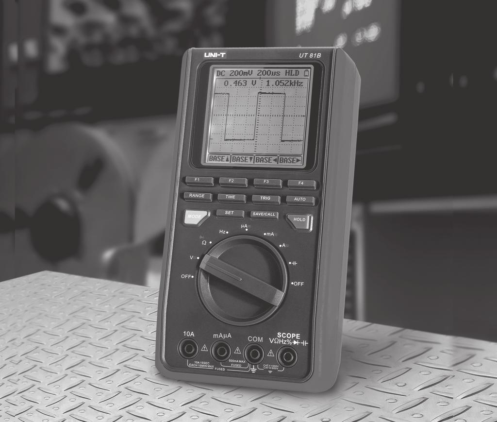
The Meter Structure The Figure 2-1 shows the Meter structure.
|
|
|
- Lucy Thompson
- 5 years ago
- Views:
Transcription
1 P/N: X
2 The Meter Structure The Figure 2-1 shows the Meter structure. 1. USB Terminals 2. LCD Display 3. Functional Buttons 4. Rotary Switch 5. Power adaptor Input Terminals 6. 10A Input Terminal 7. maµa Input Terminals 8. COM Input Terminal 9. Other Input Terminals Figure 2-1. Meter Structure 12
3 Functional Buttons The buttons activate features that augment the function selected with the rotary switch. The buttons are shown in Table 2-2. Figure 2-2. Functional Buttons Buttons F1, F2, F3 and F4 Range Time Trig Auto Table 2-2. Functional Buttons Description Software functional buttons, details please refer to the below. Under scope mode, Press Range button to switch between DC and AC measurement Under scope mode, press Time button to set the X-axis of time base. Under scope mode, press Trig button to change the trigger mode. In multimeter mode: Press Auto button to enter autoranging mode when measuring resistance, voltage and current. This button is invalid when measuring capacitance, diode, continuity buzzer and capacitance. In scope mode: Press Auto button to set the amplitude and time base to auto. 13
4 Table 2-2. Functional Buttons Buttons Mode Set Save/Call Hold Description To switch between waveform display (scope mode) and digital reading (multimeter mode). This button is only valid when under voltage, frequency, currents mode. Press Set button to set the auto power off, backlight, contrast and beep Under scope mode, press Save/Cal to store and recall data. Press Hold button to enter or exit hold mode. 14
5 Chapter 3 Making Measurement Introduction Chapter 3 explains how to make measurements. You could turn the Meter off by turning to OFF position or set up the sleep mode from 1-30 minutes. Please must ensure the Meter is not under sleep mode if you turn the Meter on but without display. To avoid false readings, which could lead to possible electric shock or personal injury, replace the battery as soon as the battery indicator appears. Based on the working environment to set up sleep mode, contrast, beep Press Set button to set the auto power off, display backlight, contrast and beep Auto off Bk Light Contrast Beep F1 F2 F3 F4 F1: Set auto power off time Auto off 15 ENTER F1 F2 F3 F4 The time level is from OFF, 1 to 30 minutes. Press F4 to confirm, save and return. Press functional button to exit and the setting remains unchanged. 15
6 F2: Set the Display Backlight BK Light 15 ENTER F1 F2 F3 F4 The brightness level from 0 to 31. Press F4 to confirm, save and return. Press functional buttons to exit, the setting is kept, but will not save. The setting will be lost after power off. F3: Set the LCD contrast Contrast 15 ENTER F1 F2 F3 F4 The contrast level from 0 to 31. Press F4 to confirm, save and return. Press functional buttons to exit, the setting is kept, but will not save. The setting will be lost after power off. F4: Set the beeps features, it can only be used under resistance, diode and continuity measurement. Beep ON OFF ENTER F1 F2 F3 F4 F2 : F3 : F4 : to turn the beep on to turn the beep off to confirm, save and return Press functional buttons to exit, the setting is kept, but will not save. The setting will be lost after power off. 16
7 Turn the rotary switch to ACV, DCV, Hz, ACA or DCA range, the Meter displays digital reading (Multimeter mode). Press Mode to switch to waveform display (scope mode) as below Figure 4. When entering scope mode, time base is auto trace, the amplitude is manual set, you may need to re-set them. You could set the trigger level as well if it is needed. Details of measurement operation of ACV, DC, Hz, ACA or DCA can be seen from B. Digital Multimeter Mode: Press Range to switch between DC and AC measurement. When the frequency and amplitude of a waveform is unknown, press Auto : When the amplitude is set to auto, the amplitude indicator will be shown white text in black background. When the amplitude is set to manual, the amplitude indicator will be shown black text in white background. When the time base is set to auto, the time base indicator will be shown white text in black background. When the time base is set to manual trace, the time base indicator will be shown black text in white background. When the time base is between 20ms - 100ns, it is possible to set the auto. When the time base is between 50ms - 5s, the auto feature will be in valid. Figure 3-1. Waveform Display 17
8 Y-axis adjustment: Press Range button under scope mode, the corresponding functional button: Move Move Rang Rang F1 F2 F3 F4 F1: move up the waveform F2: move down the waveform F3: go up range F4: go down a range F1: increase the number of periods F2: decrease the number of periods. F3: trigger point move left F4: trigger point right move The auto set feature will be off when changing the measurement mode. The auto set feature will be off when changing the measurement mode Press Time button under scope mode, the corresponding functional button: Base Base Base < Base > F1 F2 F3 F4 18
9 Press Trig button under scope mode, the corresponding function buttons: Trig Trig Auto/Norm/Shot Slop Rrise/Fall F1 F2 F3 F4 F1: move the trigger level up F2: move the trigger level down F3: select the trigger mode: auto, normal or single F4: slope adjustment: rise or fall iv. Waveform data save and recall Press Save/Call button under scope mode, the corresponding functional buttons: Save/Call 1 Enter F1 F2 F3 F4 F1: save or recall F2 and F3: select location (location from 0-9, total 10 location) F4: confirm When saving the data, it will overwrite the current data in the location no matter that location has data or not. If you recall the location has no data, the meter will appear error message, you need to press HOLD button to continue measurement, If you recall the location has data, it will save the current setting and display the data, the LCD top left shows REV to indicate recalling mode is on. Press HOLD button to return to working mode and continue measurement. You could continue recalling under recall mode or save the data. Recall mode can be used under any scope mode. For example, it is possible to recall the waveform or data saved from voltage or frequency mode when the meter is under current measurement mode. Recall mode can be worked under any waveform mode. For example: the Meter is at current mode but recalling the waveform or data which are saved under voltage or frequency mode. The Meter must 19
10 be returned to working mode to carry out measurement. B. Digital Multimeter Mode In order to have more accurate waveform, user can buy an optional BNC probe and scope probe to decrease signal attenuates. The scope probe directly connect to the BNC probe. When measuring voltage and frequency signal, connect the BNC black probe to the COM input terminal and the red probe to the voltage terminal. When measuring current signal, connect BNC black probe to the COM terminal and the red probe to ma terminal. Don t connect the BNC probe to the 10A terminal. Warning To avoid harms to you or damages to the Meter from electric shock, please do not attempt to measure voltages higher than DC 1000V, AC 750V, although readings may be obtained. To measure voltages, set up the Meter as Figure 3-2 and do the following: 1. Insert the red test lead into the V terminal and the black test lead into the COM terminal. 2. Set the rotary switch to V. 3. Connect test leads across with the object being measured. 4. The measured value shows on the display. 5. Press MODE button to toggle between Multimeter mode and Scope mode. 6. Press F1 to toggle between AC and DC voltage measurement. 20
11 When measuring voltage, the corresponding functional buttons AC / DC REL Rang Rang F1 F2 F3 F4 F1: toggle between AC or DC F2: relative mode (REL will be displayed at the right bottom of the LCD when it is on) F3: select a range up F4: select a range down Note: Figure 3-2. Voltages Measurement After changing the measurement mode, the autoranging will be off automatically and the AUTO will be disappeared at the bottom left of the LCD. When voltage measurement has been completed, disconnect the connection between the testing leads and the circuit under test and remove testing leads away from the input terminals of the Meter. 21
12 Warning If the fuse burns out during measurement, the Meter may be damaged or the operator himself may be hurt. To avoid possible damage to the Meter or to the equipment under test, check the Meter s fuses before measuring current. Use proper terminals, function, and range for the measurement. Never place the testing leads in parallel with any circuit or component when the leads are plugged into the current terminals. Turn off power to the circuit before test leads are connected in series to the return circuit to be tested. 22
13 To measure ACµA or DCµA currents, set up the Meter as Figure 3-3 and proceed as follows: 1. Insert the red test lead into the µma terminal and black test lead into the COM terminal. 2. Set the rotary switch to µa. 3. Connect the test lead in series with the return circuit to be tested. 4. The measured value shows on the display. 5. Press MODE button to toggle between Multimeter mode and Scope mode. 6. Press F1 to toggle between AC and DC current measurement. Figure 3-3. µa Range Measurement 23
14 To measure ACmA or DcmA currents, set up the Meter as Figure 3-4 and proceed as follows: 1. Insert the red test lead into the µama terminal and black test lead into the COM terminal. 2. Set the rotary switch to ma. 3. Connect the test lead in series with the return circuit to be tested. 4. The measured value shows on the display. 5. Press MODE button to toggle between Multimeter mode and Scope mode. 6. Press F1 to toggle between AC and DC current measurement. Figure 3-4. ma Range Measurement 24
15 To measure AC 10A or DC 10A currents, set up the Meter as Figure 3-5 and proceed as follows: 1. Insert the red test lead into the 10A terminal and black test lead into the COM terminal. 2. Set the rotary switch to A. 3. Connect the test lead in series with the return circuit to be tested. 4. The measured value shows on the display. 5. Press MODE button to toggle between Multimeter mode and Scope mode. 6. Press F1 to toggle between AC and DC current measurement. Figure A Range Measurement 25
16 When measuring current, the corresponding functional buttons: AC / DC REL Rang Rang F1 F2 F3 F4 F1: toggle between AC or DC F2: relative mode (REL will be displayed at the right bottom of the LCD when it is on) F3: select a range up F4: select a range down Note After changing the measurement mode, the autoranging will be off automatically and the AUTO will be disappeared at the bottom left of the LCD. If the value to be measured is unknown, use the maximum measurement position and reduce the range step by step until a satisfactory reading is obtained. When the measured current is 5A, continuous measurement is allowed. When the measured current is between 5A-10A, continuous measurement 10 seconds and interval more than 15 minutes. When current measurement has been completed, disconnect the connection between the testing leads and the circuit under test and remove testing leads away from the input terminals of the Meter. 26
17 Warning To avoid possible damages to the Meter or to the devices under test, disconnect circuit power and discharge all the high-voltage capacitors before measuring resistance. To measure resistance, set up the Meter as shown in Figure 3-6 and follow the following procedure: Figure 3-6. Resistance Measurement 27
18 1. Insert the red test lead into the Ω terminal and the black test lead into the COM terminal. 2. Set the rotary switch to Ω 3. Connect the test leads across with the object being measured. 4. The measured value shows on the display. When measuring resistance, the corresponding functional buttons: RES REL Rang Rang F1 F2 F3 F4 F1: toggle to diode mode F2: relative mode F3: select to a range up F4: select to a range down Note When measuring low resistance, the test leads can add 0.1Ω to 0.2Ω of error to resistance measurement. To test the leads, touch the probe tips together and read the resistance of the leads. Take the reading obtained to subtract the resistance of the leads to get the final reading. For high-resistance measurement (>1MΩ) or low resistance measurement (<40Ω), it is normal taking several seconds to obtain a stable reading. The LCD displays OL indicating open-circuit without input. When resistance measurement has been completed, disconnect the connection between the testing leads and the circuit under test and remove testing leads away from the input terminals. 28
19 Warning To avoid harms to you, please do not attempt to input voltages higher than 60V DC or 42V rms AC. To test the diode out of a circuit, set up the Meter as Figure 3-7 and proceed as follows: To avoid damages to the Meter or to the devices under test, disconnect circuit power and discharge all the high-voltage capacitors before testing diodes. Use the diode test to check diodes, transistors, and other semiconductor devices. The diode test sends a current through the semicondutor junction, then measure the voltage drop across the junction. A good silicon junction drops between 0.5V and 0.8V Figure 3-7. Diode Test 29
20 1. Insert the red test lead into the Ω terminal and the black test lead into the COM terminal. 2. Set the rotary switch to Ω. 3. For forward voltage drop readings on any semiconductor component, place the red test lead on the component s anode and place the black test lead on the component s cathode. The red test lead polarity is + while the black test lead polarity is. The measured value shows on the display. When measuring diode, the corresponding functional buttons: DIODE REL F1 F2 F1: toggle to continuity buzzer F2: relative mode Note Connect the test leads to the proper terminals as said above to avoid error display. The LCD will display OL indicating either open circuit or wrong polarity connection. The unit of diode is volt (V), displaying the positiveconnection voltage-drop value. When diode testing has been completed, disconnect the connection between the testing leads and the circuit under test and remove the test leads away from the input terminals. 30
21 Warning To avoid harms to you, please do not attempt to input voltage higher than 60V DC or 42V rms AC. To test for continuity, set up the Meter as Figure 3-8 and do the following: To avoid possible damages to the Meter or to the devices under test, disconnect circuit power and discharge all the high-voltage capacitors before measuring continuity. Figure 3-8. Continuity Test 31
22 1. Insert the red test lead into the W terminal and the black test lead into the COM terminal. 2. Set the rotary switch to Ω. 3. Connect the test leads across with the object being tested. 4. The tested circuit overload resistance value shows on the display. 5. The beeper comes on continuously for open conditions, that is test resistance 10W. 6. The beeper does not sound when the test resistance is 100W Note When continuity testing has been completed, disconnect the connection between the testing leads and the circuit under test and remove the test leads away from the input terminals. When measuring continuity buzzer, the corresponding functional buttons: CONTINUITY REL F1 F2 F1: toggle to resistance measurement mode F2: relative mode 32
23 Warning To avoid harms to you, please do not attempt to input voltage higher than 42V rms. To measure frequency and duty cycle, connect the Meter as Figure 3-9 and do the following: 1. Insert the red test lead into the Hz terminal and the black test lead into the COM terminal. 2. Set the rotary switch to Hz. 3. Connect the test leads across with the object being measured. 4. The measured value shows on the display. 5. Press MODE button to toggle between Multimeter mode and Scope mode. 6. Press F1 to toggle between frequency and duty cycle measurement. When measuring frequency and duty cycle, the corresponding functional buttons: Freq/Duty F1 F1: toggle between frequency and duty cycle Figure 3-9. Measuring Frequency / Duty Cycle 33
24 Note The requirement of Input amplitude a is as follows: When 1MHz: 300 mv a 30Vrms; 1MHz: 600 mv a 5Vrms It is normal to have few seconds run time when switch from other functions to these functions. When Hz or duty cycle measurement has been completed, disconnect the connection between the testing leads and the circuit under test and remove the test leads away from the input terminals. 34
25 Warning To ensure accuracy, the Meter inside is discharged against the tested capacitor To measure capacitance, set up the Meter as shown in Figure 3-10 and proceed as follows: To avoid damage to the Meter or to the equipment under test, disconnect circuit power and discharge all high-voltage capacitors before measuring capacitance. Figure Measuring Capacitance 35
26 Insert the red test lead into theterminal and the black test lead into the COM terminal. Set the rotary switch to measurement mode, the Meter may display a fixed reading which is a internal distributed capacitor value. For testing less than 40nF capacitor, the tested value must subtract the internal distributed capacitor value to maintain the accuracy. To improve the accuracy, press F2 REL with the test leads open to subtract the residual capacitance of the Meter and the test leads. It is recommended to use as short as test lead carrying out measurement to reduce the effect of internal distributed capacitor. When measuring capacitance, the corresponding functional buttons: Capacity REL F1 F2 F2: relative mode Note Capacitors larger than 10 F take longer time. If the tested capacitor has polarity, connect the red test lead to positive side and black test lead to negative side. When capacitance measurement has been completed, disconnect the connection between the testing leads and the circuit under test and remove the test leads away from the input terminals of the Meter. 36
27 Chapter 4 Using Software When using the Software, please refer to the Installation Guide of the included CD-ROM. 37
28 Chapter 5 Maintaining The Test Tool This chapter provides basic maintenance information including battery and fuse replacement instruction. high temperature, explosive, inflammable and strong magnetic field. Do not attempt to repair or service your Meter unless you are qualified to do so and have the relevant calibration, performance test, and service information. 38 Warning A. General Service Periodically wipe the case with a damp cloth and mild detergent. Do not use abrasives or solvents. To clean the terminals with cotton bar with detergent, as dirt or moisture in the terminals can affect readings. Turn the Meter to OFF when it is not in use. Take out the battery when it is not using for a long time. Do not use or store the Meter in a place of humidity,
29 B. Replacing the Fuses 1.Remove the battery compartment 2.Remove the case bottom Figure 5-1. Fuse Replacement 0.5A/1000V 10A/1000V 3.Install fuses with correct type and specification Warning To avoid electrical shock or arc blast, or personal injury or damage to the Meter, use specified fuses ONLY in accordance with the following procedure. Follow Figure 5-1 and proceed as follows to replace the Meter s fuse: Turn the rotary switch to OFF and remove all connections from the terminals. Remove the screw from the battery compartment, and separate the battery compartment from the case bottom. Remove the three screws from the case bottom, and separate the case bottom from the case top. Remove the fuse by gently prying one end loose, then take out the fuse from its bracket. Install ONLY replacement fuses with the identical type and specification as follows and make sure the fuse is fixed firmly in the bracket. Fuse 1: F0.5A/1000V Φ mm Fuse 2: F10A/1000V Φ mm Rejoin the case bottom and case top, battery compartment and case bottom, and install the 5 screws. Replacement of the fuses is seldom required. Burning of a fuse always results from improper operation. 39
30 C. Replacing the Battery Warning To avoid false readings, which could lead to possible electric shock or personal injury, replace the battery as soon as the battery indicator appears. Make sure the test leads are disconnected from the circuit being tested before opening the case bottom. Follow Figure 5-2 and proceed as follows to replace the battery: Figure 5-2. Battery Replacement Turn the rotary switch to OFF and remove all connections from the terminals. Remove the screw from the battery compartment, and separate the battery compartment from the case bottom. Replace with 4 pieces new 1.5V (R6P) batteries. Rejoin the case bottom and battery compartment, and reinstall the screw. 40
31 Chapter 6 Specifications Safety and Compliances Maximum Voltage between any Terminal and Grounding Certification Compliances Fused Protection for ma input terminal: Fused Protection for 10A input terminal: Refer to different range input protection voltage IEC CAT. II 1000V, CAT.III 600V overvoltage and double insulation standard F0.5A/1000V Φ mm F10A/1000V Φ mm 41
32 Physical Specifications Display (LCD) Operating Temperature Storage Temperature Relative Humidity Altitude Battery Type Electromagnetic Compatibility Dimensions (H x W x L) Weight Digital: 3999 counts on display ; updates 2-3 times / second. 0 o C~40 o C (32 o F~104 o F) -10 o C~50 o C (14 o F~122 o F) 0 o C~40 o C; -10 o C~50 o C. Operating: 2000m; Storage: 10000m. 1.5V (R6) x 4 Batteries or Power adaptor. Check carefully about the working voltage of power adaptor before use. In a radio field of 1 V/m below: Overall Accuracy = Specified Accuracy + 5% of Range In a radio field of 1 V/m above: No assigned accuracy is specified. 200 x 100 x 48mm. Approx. 498g (including battery) 42
33 General Specifications ( Digital Multimeter) Range Polarity Overloading Battery Deficiency When it is under Multimeter mode, you could select either auto or manual ranging. Auto, negative polarity displays - Display OL Display General Specifications (Scope) Display Auto setting Overloading Memory USB Tilt Stand 160 x 160 Monochrome Auto set the Meter according to the tested signal size Display OL 10 screens and setups Optically isolated to ensure safety Allowing viewing at a convenient position and angle. 43
34 Feature Summary Display Autorange Continuity Duty Cycle Battery Access Door 160 x 160 Monochrome When it is under multimeter mode, the Meter automatically selects best range Beeper sounds for resistance readings below threshold. Measure signal on or off time in %. Battery replaceable. Basic Specifications (Digital Multimeter) Function DC Voltage AC Voltage Basic Accuracy DC Current AC Current Resistance Capacitance Frequency Ranges / Description 0 to 1000V 0 to 750V DC Voltage: 0.8% AC Voltage: 1% 0 to 10A 0 to 10A 0 to 40MΩ 0 to 100µF 0~10MHz 44
35 Basic Specifications (Scope) Sampling rate Sampling rate / Scale Updating rate Trigger types Timebase Range Timebase accuracy Horizontal 40M per second 20 pixels >5 Free Run / Normal / Single Shot 100ns/div~5 sec /div (1-2-5) (0.1% + 1pix) Bandwidth Channel Coupling Voltage resolution Input Impedance Accuracy Maximum input voltage Voltage Sensitivity Vertical UT81A:2MHz,UT81B:8MHz Single DC 8 Bits 10MΩ (excluding Multimeter part) (5%+1pix) 1000Vp-p 20mV/div~500V/div (1-2-5) Detailed Accuracy Specifications Accuracy: ([% of reading] + [number of least significant digits]), guarantee for 1 year. Operating temperature: 18 o C~28 o C Relative humidity: <75%RH 45
36 A. DC Voltage Range Resolution Accuracy Overload Protection Input Impedance 400mV 4V 40V 400V 1000V B. AC Voltage 100µV 1mV 10mV 100mV 1V (0.8%+8) (0.1%+8) 1000V DC or AC Around 10MΩ (excluding waveform) Range Resolution Accuracy Overload Protection Input Impedance 4V 40V 400V 750V 1mV 10mV 100mV 1V (1%+15) (1.2%+15) 1000V DC or AC Around 10MΩ (excluding waveform) 46
37 C. DC Current Range Resolution Accuracy Overload Protection 400µA 4000µA 40mA 400mA 4A 10A 0.1µA 1µA 10µA 100µA 1mA 10mA (1%+8) (1.2%+8) (1.5%+8) F0.5A/1000V Φ mm F10A/1000V Φ mm (Continuous measurement 10 seconds and interval more than 15 minutes.) 47
38 D. AC Current Range Resolution Accuracy Overload Protection 400µA 4000µA 40mA 400mA 4A 10A 0.1µA 1µA 10µA 100µA 1mA 10mA (1.5%+8) (2%+8) (2.5%+5) F0.5A/1000V Φ mm F10A/1000V Φ mm (Continuous measurement 10 seconds and interval more than 15 minutes.) 48
39 E. Resistance Range Resolution Accuracy Overload Protection 400Ω 4kΩ 0.1Ω 1Ω (1.2%+5) 40kΩ 10Ω (1%+5) 400kΩ 100Ω 1000VDC or AC rms 4MΩ 40MΩ 1kΩ 10kΩ (1.2%+5) (1.5%+5) F. Diode Test Range Resolution Overload Protection Remarks 1mV 1000V DC or AC A good silicon junction drops between 0.5V and 0.8V. 49
40 G. Continuity Test Test Range Resolution Overload Protection Remarks 0.1Ω 1000V DC or AC The buzzer sounds when the test resistance is 10Ω. The buzzer does not sound when the test resistance is 100Ω. H. Frequency and Duty Cycle % Range Resolution Accuracy Overload Protection 10Hz~10MHz 0.1%~99.9% 0.001Hz 0.1% (0.1%+3) Reading for reference only 1000V DC or AC rms 50
41 I. Capacitance Range Resolution Accuracy Overload Protection 40nF 400nF 4µF 40µF 100µF 10pF 100pF 1nF 10nF 100nF Under REL mode: (3%+10) (3%+8) (4%+8) 1000V DC or AC rms 51
OS-81B TECPEL CO. LTD.
 OS-81B TECPEL CO. LTD. Table of Contents Chapter Title Page 1 Before You Start Overview Unpacking Inspection Safety Information Rules For Safe Operation International Electrical Symbols 2 Using The Testing
Model : OPERATING MANUAL Table of Contents (1)
") Table of Contents (1) Title Overview Unpacking Inspection Safety Information Rules For Safe Operation International Electrical Symbols The Meter Structure Functional Buttons Measurement Operation A. DC
Table of Contents (1) Title Overview Unpacking Inspection Safety Information Rules For Safe Operation International Electrical Symbols The Meter Structure Functional Buttons Measurement Operation A. DC
Table of Contents Title Page
 Table of Contents Title Page Overview Unpacking Inspection Safety Information Rules For Safe Operation International Electrical Symbols The Meter Structure Rotary Switch Functional Buttons Display Symbols
Pocket Size Digital Multimeter with USB Model: A & A
 Pocket Size Digital Multimeter with USB Model: 72-7730A & 72-7732A 1 IMPORTANT SAFETY INFORMATION Please read these instructions carefully before use and retain for future reference. This instrument is
Table of Contents GDM-356. Page
 Table of Contents Title Overview Unpacking Inspection Safety Information Rules For Safe Operation International Electrical Symbols The multimeter Structure Functional Buttons Display Symbols Measurement
UT207A/208A/209A Operating Manual. Table of Contents
 Table of Contents Title Overview Unpacking Inspection Safety Information Rules for Safe Operation International Electrical Symbols The Meter Structure Display Symbols Functional Buttons The Effectiveness
User Manual Digital Multimeter. model no.: MSR-U1000
 User Manual Digital Multimeter model no.: MSR-U1000 This Operating Manual covers information on safety and cautions. Please read the relevant information carefully and observe all the Warnings and Notes
User Manual Digital Multimeter
 User Manual Digital Multimeter model no.: MSR-R500 Questions or Concerns? support@etekcity.com visit etekcity.com for more products Safe and Proper Usage Thank you for purchasing the Etekcity MSR-R500
OPERATOR S INSTRUCTION MANUAL M-2625 AUTO RANGING DIGITAL MULTIMETER
 OPERATOR S INSTRUCTION MANUAL M-2625 AUTO RANGING DIGITAL MULTIMETER with Temperature Probe Copyright 2007 Elenco Electronics, Inc. Contents 1. Safety Information 3,4 2. Safety Symbols 5 3. Front Plate
Model UT20B: OPERATING MANUAL Table of Contents (1)
") Table of Contents (1) Title Overview Unpacking Inspection Safety Information Rules For Safe Operation International Electrical Symbols Rotary Switch Display Symbols Measurement Operation A. AC Voltage
Table of Contents (1) Title Overview Unpacking Inspection Safety Information Rules For Safe Operation International Electrical Symbols Rotary Switch Display Symbols Measurement Operation A. AC Voltage
KMD-S04 Multímetro de bolsillo
 www.grupotemper.com KMD-S04 Multímetro de bolsillo Table of Contents Title Page Overview ~~~~~~~~~~~~~~~~~~~~~~~~~~~~~~~~~~~~~~~~~~ 3 Unpacking Inspection ~~~~~~~~~~~~~~~~~~~~~~~~~~~~~~~~~ 4 Safety Information
Model A/ A: OPERATING MANUAL TABLE OF CONTENTS
 72-7730A 72-7732A TABLE OF CONTENTS CHAPTER TITLE PAGE 1. Before You Start Overview Inspection Safety Information Rules For Safe Operation International Electrical Symbols 2. Getting Acquainted Turning
DVM1190 DIGITAL MULTIMETER
 DIGITAL MULTIMETER 1. Introduction Thank you for buying the. This digital multimeter has a large LCD, a data-hold function and a backlight. The device uses a very practical safety mechanism that keeps
Model UT39A/B/C: OPERATING MANUAL
 TABLE OF CONTENTS TITLE PAGE Overview Unpacking Inspection Safety Information Rules For Safe Operation International Electrical Symbols The Meter Structure Functional Buttons Display Symbols Measurement
User Manual Digital Clamp Multimeter. model no.: MSR-C600
 User Manual Digital Clamp Multimeter model no.: MSR-C600 Overview This Operating Manual covers information on safety and cautions. Please read the relevant information carefully and observe all the Warnings
Handheld Digital Multimeter
 Handheld Digital Multimeter GDM-397, GDM-461 USER MANUAL GW INSTEK PART NO. 82DM-46100M01 ISO-9001 CERTIFIED MANUFACTURER This manual contains proprietary information, which is protected by copyright.
Model UT10A: OPERATING MANUAL Table of Contents (1)
") Table of Contents (1) Table of Contents Title Page Overview Unpacking Inspection Safety Information Rules For Safe Operation International Electrical Symbols The Meter Structure Functional Buttons Measurement
Table of Contents (1) Table of Contents Title Page Overview Unpacking Inspection Safety Information Rules For Safe Operation International Electrical Symbols The Meter Structure Functional Buttons Measurement
Handheld Digital Multimeter
 Handheld Digital Multimeter GDM-360, GDM-397, GDM-398, GDM-461 USER MANUAL GW INSTEK PART NO. 82DM-46100MA1 ISO-9001 CERTIFIED MANUFACTURER This manual contains proprietary information, which is protected
Model UT50D: OPERATING MANUAL. Table of Contents
 Table of Contents Overview Unpacking Inspection Safety Information Rules For Safe Operation International Electrical Symbols The Meter Structure Functional Buttons Display Symbols Measurement Operation
AMM-1022 Digital Multimeter USER`S MANUAL
 Digital Multimeter USER`S MANUAL www.tmatlantic.com CONTENTS 1. SAFETY INFORMATION.3 2. DESCRIPTION..6 3. SPECIFICATIONS.8 4. OPERATING INSTRUCTION..11 4.1 Voltage measurement...11 4.2 Current measurement
UT804 P/N: Bench Type. Digital Multimeter
 PMS 425C PMS 1797C UT804 Bench Type Digital Multimeter P/N: 41451520 Model UT804 OPERATING MANUAL Table of Contents Chapter Title Page 1. Before You Start Overview Unpacking Inspection Safety Information
Model UT201/202: OPERATING MANUAL. Table of Contents
 Table of Contents Title Overview Unpacking Inspection Safety Information Rules For Safe Operation International Electrical Symbols The Meter Structure Rotary Switch Functional Buttons The Effectiveness
AC/DC CLAMP METER USER S MANUAL
 AC/DC CLAMP METER USER S MANUAL CONTENTS PAGE SAFETY INFORMATION SYMBOL EXPLANATION SAFETY PRECAUTIONS 1 1 2 MAINTENANCE 3 GENERAL DESCRIPTION 4 PANEL DESCRIPTION 4 OPERATING INSTRUCTIONS... 7 SPECIFICATIONS
1. SAFETY INFORMATION.1 2. DESCRIPTION SPECIFICATIONS.6 4. OPERATING INSTRUCTION Voltage measurement Current measurement 10
 CONTENTS 1. SAFETY INFORMATION.1 2. DESCRIPTION..4 3. SPECIFICATIONS.6 4. OPERATING INSTRUCTION..9 4.1 Voltage measurement...10 4.2 Current measurement 10 4.3 Resistance measurement...12 4.4 Diode test.12
Pocket Size Digital Multimeter Models: and
 Pocket Size Digital Multimeter Models: 72-8150 and 72-8155 1 IMPORTANT SAFETY INFORMATION Please read these instructions carefully before use and retain for future reference. Please operate according to
Digital Clamp Meter Model: &
 Digital Clamp Meter Model: 72-7224 & 72-7226 1 SAFETY INFORMATION Please read these instructions carefully before use and retain for future reference. This meter is designed to meet IEC61010-1, 61010-2-032,
OPERATOR S INSTRUCTION MANUAL
 OPERATOR S INSTRUCTION MANUAL AUTO-RANGE DUAL DISPLAY CONFORMED IEC1010 DIGITAL MULTIMETER CONTENTS PAGE SAFETY INFORMATION..... DESCRIPTION.. OPERATING INSTRUCTION.. SPECIFICATIONS.... ACCESSORIES. BATTERY
DIGITAL MULTIMETER AUTORANGING
 MODEL: D03124 DIGITAL MULTIMETER AUTORANGING 1 CONTENTS Page Number Details 2 Introduction 2 What s Included 3 Important Safety Information 3 Symbol Guide 4 Overview 5 Buttons 5 Display Indicators 6 General
DVM98. True RMS Digital Multimeter. 1 Safety information. 1.1 Preliminary. 1.2 During use
 True RMS Digital Multimeter DVM98 1 Safety information This multimeter has been designed according to IEC - 1010 concerning electronic measuring instruments with an overvoltage category (CAT II) and pollution
Model UT71C/D/E OPERATING MANUAL
 Model UT71C/D/E OPERATING MANUAL CHAPTER TITLE PAGE 1. 2. Before You Start Overview Unpacking Inspection Safety Information Rules For Safe Operation International Electrical Symbols Getting Acquainted
Thank you again for choosing AstroAI, if you have any questions or concerns regarding your product, please contact us at
 ASTROAI USER MANUAL DT132A 4000 Count Auto-Ranging Multimeter Thank you for purchasing the AstroAI DT132A 4000 Count Auto-Ranging Multimeter. It is a 3 ¾ digit, 3999 counts, auto-ranging digital multimeter.
Title Page Overview Unpacking Inspection Safety Information
 Table of Contents Title Page Overview Unpacking Inspection Safety Information 3 4 5 Rules For Safe Operation International Electrical Symbols The Meter Structure Rotary Switch Functional Buttons Display
Contents 1. General instructions. 1.1 Precautions safety measures Protection mechanisms. 2. Description. 2.1 Instrument Familiarization. 2.
 Contents 1. General instructions. 1.1 Precautions safety measures... 1.2 Protection mechanisms. 2. Description. 2.1 Instrument Familiarization. 2.2 LCD Display 2.3 Keypad. 3. Function description. 3.1
User Manual. All rights reserved. Specifications are subject to change without notice.
 User Manual All rights reserved. Specifications are subject to change without notice. LIMITED WARRANTY AND LIMITATION OF LIABILITY Customers enjoy one-year warranty from the date of purchase. This warranty
Model UT61A/61B/61C/61D/61E: OPERATING MANUAL. Table of Contents
 Table of Contents Title Overview Unpacking Inspection Safety Information Rules For Safe Operation International Electrical Symbols The Meter Structure Rotary Switch Functional Buttons Display Symbols Measurement
DIGITAL MULTIMETER OPERATOR'S INSTRUCTION MANUAL HOLD 10A COM LIGHT MS8265 ON/OFF. 200M KHz 2K 20K μ μ μ n.
 MS8265 DIGITAL MULTIMETER OPERATOR'S INSTRUCTION MANUAL HOLD ON/OFF LIGHT 1000V CAT II 600V CAT III MS8265 200K 2M 20M 20K 200M KHz 2K 20 200 2 20 200μ 200 20μ 750 2μ 1000 200n F 20n 10A 2m 200m 10 10
Internetowy sklep elektroniczny. Kontakt. Tel Tel. Kom Fax
 DOKUMENT TEN JEST PRZEZNACZONY DLA KLIENTÓW FIRMY Internetowy sklep elektroniczny WWW.DIOLUT.PL Kontakt Tel. +48 0334866616 Tel. Kom. +48 0888139522 Fax. +48 0334866617 e-mail diolut@diolut.pl Table of
IDEAL INDUSTRIES, INC. TECHNICAL MANUAL MODEL: MODEL: Multimeter Service Information
 IDEAL INDUSTRIES, INC. TECHNICAL MANUAL MODEL: 61-340 MODEL: 61-342 Multimeter Service Information The Service Information provides the following information: Precautions and safety information Specifications
Sales: Technical: Fax:
 DATA SHEET Order code Manufacturer code Description 85-0733 n/a n/a The enclosed information is believed to be correct, Information may change without notice due to product improvement. Users should ensure
UT207/208. Digital Clamp Multimeter P/N:
 UT207/208 Digital Clamp Multimeter P/N: 41451522 Model UT207/208 OPERATING MANUAL Table of Contents Title Overview Unpacking Inspection Safety Information Rules For Safe Operation International Electrical
USER MANUAL 600A AC Clamp Meter + NCV Model MA610
 USER MANUAL 600A AC Clamp Meter + NCV Model MA610 Additional User Manual Translations available at www.extech.com Introduction Thank you for selecting the Extech MA610 Clamp Meter. This meter measures
PEN TYPE DIGITAL MULTIMETER OPERATION MANUAL T8211D
 PEN TYPE DIGITAL MULTIMETER OPERATION MANUAL T8211D T8211D 1 1. SAFETY INFORMATION BE EXTREMELY CAREFUL IN THE USE OF THIS METER. Improper use of this device can result in electric shock or destroy of
OPERATOR S INSTRUCTION MANUAL DIGITAL MULTIMETER
 OPERATOR S INSTRUCTION MANUAL DIGITAL MULTIMETER SAFETY INFORMATION This multimeter has been designed according to IEC 1010 concerning electronic measuring instruments with an overvoltage category (CATⅡ)
EX350 Series USER GUIDE. True RMS Digital Multimeters. EX350 True RMS Digital Multimeter EX355 True RMS Digital Multimeter with Temperature
 USER GUIDE True RMS Digital Multimeters EX350 Series EX350 True RMS Digital Multimeter EX355 True RMS Digital Multimeter with Temperature Table of Contents 1. INTRODUCTION 3 2. SAFETY INFORMATION 4 3.
1. SAFETY 1.1. SAFETY INFORMATION 1.2. SAFETY SYMBOLS
 To all residents of the European Union Important environmental information about this product This symbol on the device or the package indicates that disposal of the device after its lifecycle could harm
ETHOS 5030 TRUE-RMS DIGITAL MULTIMETER OPERATION MANUAL
 ETHOS 5030 TRUE-RMS DIGITAL MULTIMETER OPERATION MANUAL 1 1. SAFETY INFORMATION SAFETY SYMBOLS Warning! Dangerous Voltage (Risk of electric shock). Caution! Refer to the user s manual before using this
DIGITAL MULTIMETER CONTENTS DIGITAL MULTIMETER CONTENTS
 CONTENTS CONTENTS CONTENTS 1. SAFETY INFORMATION...1 1.1 Preliminary...1 1.2 Dos and don ts...2 1.3 Symbols...3 1.4 Precautions...4 2. DESCRIPTION...5 2.1 Names of parts...6 2.2 Switches, buttons and input
True RMS Digital Multimeter Model:
 True RMS Digital Multimeter Model: 72-7780 1 SAFETY INFORMATION Please read these instructions carefully before use and retain for future reference. This meter is designed to meet IEC61010-1, 61010-2-032,
Item ref: UK MTM01 DIGITAL MULTITESTER. User Manual
 Item ref: 600.100UK MTM01 DIGITAL MULTITESTER User Manual Please read this manual thoroughly and ensure all contents are fully understood before using the apparatus. Warning To avoid possible electric
VC820/VC840 OPERATING MANUAL. Table of Contents
 Table of Contents Title Overview Unpacking Inspection Safety Information Rules For Safe Operation Electrical Symbols Functional Structure Rotary Switch Functional Buttons Display Symbols Manual Ranging
Model UT511 OPERATING MANUAL
 Model UT511 OPERATING MANUAL TITLE PAGE Introduction Unpacking the Meter Safety Information International Electrical Symbols Battery Saver (Sleep Mode) Battery Indication The Meter Structure Display Key
Mini Clamp Meter Model:
 Mini Clamp Meter Model: 72-2985 1 CONTENTS Page Number Details 2 What s Included 3 Important Safety Information 3 Technical Specification 4 Product Overview 5 LCD Overview 6 Operation - AC/DC Voltage Measurement
METRAVI. Table of Contents
 Table of Contents A. Your Meter s Feature B. Specifications C. Making Measurements D. Maintenance E. Accessories F. Using Holster G. Using Strap Introduction 540 is brand new Multimeter with 4 1/2 digits,
HANDHELD DIGITAL MULTIMETER OPERATOR S INSTRUCTION MANUAL
 HANDHELD DIGITAL MULTIMETER OPERATOR S INSTRUCTION MANUAL GENERAL INSTRUCTIONS This instrument complies with IEC 1010-1 (61010-1@IEC: 2001), CAT. II 1000V and CAT. III 600V overvoltage standards. See Specifications.
400Amp True RMS AC/DC Clamp Meter Model EX613
 User's Guide 400Amp True RMS AC/DC Clamp Meter Model EX613 Introduction Congratulations on your purchase of this Extech EX613 True RMS Clamp Meter. This meter measures AC Current, DC Current, AC/DC Voltage,
Model ST Instruction Manual. True RMS Autoranging Digital Multimeter. reedinstruments. www. com
 Model ST-9933 True RMS Autoranging Digital Multimeter Instruction Manual reedinstruments com Table of Contents Safety... 3 Features... 4 Specifications...4-8 Technical...4-5 Accuracy...5-8 Display Description...
Model UT70C: OPERATING MANUAL. Table of Contents. Page
 Table of Contents Title Overview Unpacking Inspection Safety Information Rules For Safe Operation International Electrical Symbols The Meter Structure Rotary Switch Functional Buttons Display Symbols Measurement
MS8250D DUAL DISPLAY DIGITAL MULTIMETER User s Manual
 DUAL DISPLAY DIGITAL MULTIMETER User s Manual MS8250D 1. Safety Information Warning Use caution and follow all safety guidelines to prevent electric shock or damage to the meter. Please ready carefully
MS8211 DIGITAL MULTIMETER INSTRUCTION MANUAL
 MS8211 DIGITAL MULTIMETER INSTRUCTION MANUAL Ω CONTENTS CONTENTS 1. SAFETY INFORM...1 4.4 Range Transform...10 1.1 Preliminary...1 4.5 Auto Power Off...10 1.2 During use...2 4.6 Preparation For Measurement...11
User Manual. All rights reserved. Specifications are subject to change without notice.
 User Manual All rights reserved. Specifications are subject to change without notice. LIMITED WARRANTY AND LIMITATION OF LIABILITY Customers enjoy one-year warranty from the date of purchase. This warranty
1.General instructions Specifications Description...7
 USER S Manual CONTENTS 1.General instructions...1 1.1 Precautions safety measures...1 1.1.1 Preliminary...1 1.1.2 During use...2 1.1.3 Symbols...4 1.1.4 Instructions...5 1.2 Protection mechanisms...6 2.
VC835 DIGTAL MULTIMETER Operation Manual
 VC835 DIGTAL MULTIMETER Operation Manual CONTENTS GENERAL DESCRIPTION Safety Instructions FEATURES OPERATION MAINTENANCE TROUBLE SHOOTING 1. General Description This is a 3 1/2 digital multimeter with
MS8250A/B OPERATION MANUAL MS8250A. Hz% FUNC REL RANGE REL HOLD OFF 10A. Hz% A NCV. Hz% COM. A ma 10A FUSED 600V CAT IV.
 MS8250A/B DIGITAL MULTIMETER OPERATION MANUAL AUTO DC AC REL hfe PCLINK % C F kmωkz nµmfav MS8250A DIGITAL MULTIMETER Auto Power Off RANGE REL HOLD FUNC NCV A ma OFF 10A A ma 10A FUSED 600V CAT IV COM
DVM645BI BENCH MULTIMETER TAFELMULTIMETER MULTIMETRE DE TABLE BANCO MULTÍMETRO TISCHMULTIMETER. User Manual. Gebruikershandleiding
 BENCH MULTIMETER TAFELMULTIMETER MULTIMETRE DE TABLE BANCO MULTÍMETRO TISCHMULTIMETER User Manual Gebruikershandleiding Manuel d'utilisation Gebrauchsanleitung Introduction BENCH MULTIMETER This manual
NOTE: Fully read and understand this manual before using this Digital Multimeter.
 ASTROAI USER MANUAL AUTO RANGING DIGITAL CLAMP METER Thank you for purchasing the Auto Ranging Digital Clamp Meter from AstroAI. The AstroAI Auto Ranging Digital Clamp Meter is designed to be safely and
USER'S MANUAL ACDC-100 TRMS ACDC-100. Versatile AC/DC Clamp-on Multimeter Series
 99 Washington Street Melrose, MA 02176 Fax 781-665-0780 TestEquipmentDepot.com USER'S MANUAL ACDC-100 TRMS ACDC-100 Versatile AC/DC Clamp-on Multimeter Series 1 1) SAFETY This manual contains information
MS8268 HANDHELD DIGITAL MULTIMETER OPERATOR S INSTRUCTION MANUAL
 MS8268 HANDHELD DIGITAL MULTIMETER OPERATOR S INSTRUCTION MANUAL Table of Contents TITLE PAGE 1. GENERAL INSTRUCTIONS 1 1.1 Precaution safety measures 1 1.1.1 Preliminary 1 1.1.2 During use 2 1.1.3 Symbols
Item ref: UK MTTR01 TRUE RMS DIGITAL MULTITESTER WITH USB INTERFACE. User Manual
 Item ref: 600.104UK MTTR01 TRUE RMS DIGITAL MULTITESTER WITH USB INTERFACE User Manual Please read this manual thoroughly and ensure all contents are fully understood before using the apparatus. WARNING
USER'S MANUAL DMR-6700
 USER'S MANUAL Multimeter True RMS DMR-6700 CIRCUIT-TEST ELECTRONICS www.circuittest.com Introduction This meter measures AC/DC Voltage, AC/DC Current, Resistance, Capacitance, Frequency (electrical & electronic),
RAGU 81D DIGITAL MULTIMETER OPERATION MANUAL
 RAGU 81D DIGITAL MULTIMETER OPERATION MANUAL Contents I. General...- 1 - Ⅱ. Open-package Inspection...- 2 - III. Safety Considerations... - 3 - IV.Instrument Panel & Button Function Description...- 9 -
ProfiScale MULTI Multimeter
 1,5 V 9V 200 mv 600 V 200 ma 1/10 A ProfiScale MULTI Multimeter en Operating instructions BURG-WÄCHTER KG Altenhofer Weg 15 58300 Wetter Germany Introduction Want the reassurance of knowing whether current
Digital MultiMeter - Make your job efficiency User Instruction Manual
 Digital MultiMeter - Make your job efficiency User Instruction Manual Main Fields of Application: Process industries, Metallurgy, Power generation, Research, Laboratories, Maintenance, After sales service,
INSTRUCTION MANUAL DIGITAL MULTIMETER
 INSTRUCTION MANUAL DIGITAL MULTIMETER 600 OFF 600 20 2m 2 20m m m 2M 10A k 20k 2k O C NPN PNP hfe E B C E 10A DC 10A MAX UNFUSED MAX 600V COM V ma ma MAX FUSED CAT II 600V Thanks for buying our products,
USER MANUAL. Model MA A AC Clamp Meter DMM Model MA445 True RMS 400A AC/DC Clamp Meter DMM
 USER MANUAL Model MA440 400A AC Clamp Meter DMM Model MA443 True RMS 400 AC Clamp Meter DMM Model MA445 True RMS 400A AC/DC Clamp Meter DMM Introduction Thank you for selecting the Extech EX44x Series
AC/DC DIGITAL CLAMP METER OPERATION MANUAL
 AC/DC DIGITAL CLAMP METER OPERATION MANUAL HYS005661 A0 ACCESSORIES 6. ACCESSORIES 1) Test Leads: Electric Ratings 1000V 10A 1 pair (set) 2) Operating Manual 1 copy 3) 1.5V AAA Battery 3 piece - - 55 -
Analog Technologies VC99. Multimeter FEATURES
 FEATURES LCD Display Max Display: 6000(3 6/7) Digits Automatic Polarity, Unit Symbol and 61 Section Analog Display Measurement Method: Double Integral A/D Conversion Sampling Rate: Approx.3 times/sec Over-Range
DIGITAL MULTIMETER INSTRUCTION MANUAL
 DIGITAL MULTIMETER INSTRUCTION MANUAL 1 CONTENTS CONTENTS 1. SAFETY INFORMATION 1 1.1 PRELIMINARY 1 1.2 DURING USE 2 1.3 SYMBOLS 3 1.4 MAINTENANCE 4 2. DESCRIPTION 5 2.1 NAMES OF COMPONENTS 5 2.2 SWITCH,
DMM8900 SERIES USERS MANUAL
 DMM8900 SERIES USERS MANUAL WARRANTY This instrument is warranted to be free from defects in material and workmanship for a period of one year. Any instrument found defective within one year from the delivery
User's Guide. 800 Amp AC/DC True RMS Clamp Meter. Model EX Washington Street Melrose, MA Phone Toll Free
 User's Guide 99 Washington Street Melrose, MA 02176 Phone 781-665-1400 Toll Free 1-800-517-8431 Visit us at www.testequipmentdepot.com 800 Amp AC/DC True RMS Clamp Meter Model EX730 Introduction Congratulations
IDEAL INDUSTRIES, INC. TECHNICAL MANUAL MODEL:
 IDEAL INDUSTRIES, INC. TECHNICAL MANUAL MODEL: 61-352 The Service Information provides the following information: Precautions and safety information Specifications Basic maintenance (cleaning, replacing
Autoranging Multimeter Extech EX503
 User's Guide Autoranging Multimeter Extech EX503 Introduction Congratulations on your purchase of the Extech EX503 Autoranging Multimeter. This meter measures AC/DC Voltage, AC/DC Current, Resistance,
Model DIGITAL MULTIMETER
 Model 57070 DIGITAL MULTIMETER INSTRUCTION MANUAL SAFETY INFORMATION To ensure safe operation, and in order to exploit to the full the functionality of the meter, please follow the directions in this section
DM-45 Digital Multimeter
 INSTRUCTION MANUAL DM-45 Digital Multimeter Read and understand all of the instructions and safety information in this manual before operating or servicing this tool. Description The Greenlee DM-45 Digital
DC/AC CLAMP METER ISO-TECH 2000 USERS MANUAL
 DC/AC CLAMP METER ISO-TECH 2000 USERS MANUAL Warnings and Safety symbols: Caution, refer to this manual before using the meter. Dangerous voltages. Meter is protected throughout by double insulation or
EM420A/420B DIGITAL MULTIMETER OWNERS MANUAL Read this owners manual thoroughly before use
 http://www.all-sun.com EM420A/420B DIGITAL MULTIMETER OWNERS MANUAL V Read this owners manual thoroughly before use WARRANTY This instrument is warranted to be free from defects in material and workmanship
USER'S MANUAL AM-100 AM-105 TRMS AM-110 TRMS. Digital Multimeters
 USER'S MANUAL AM-100 AM-105 TRMS AM-110 TRMS Digital Multimeters 1 1) SAFETY This manual contains information and warnings that must be followed for operating the instrument safely and maintaining the
MS8216 DIGITAL MULTIMETER OPERATOR S MANUAL
 MS8216 DIGITAL MULTIMETER OPERATOR S MANUAL CONTENTS 1. SAFETY INFORMATION 1 1.1 PRELIMINARY 1 1.2 DURING USE 2 1.3 SYMBOLS 4 1.4 MAINTENANCE 4 2. DESCRIPTION 5 2.1 NAMES OF COMPONENTS 5 2.2 FUNCTION AND
3B SCIENTIFIC PHYSICS
 3B SCIENTIFIC PHYSICS Digital Multimeter E 1018832 Instruction sheet 12/16 SD/UD 1 probe 1a Finger guards 2 Measurement socket 10 A for current measurement in 10-A (positive) 3 Measurement socket COM (negative)
Analog Technologies. Multimeter 15B and17b
 Figure 1. The Photo of Actual 17B Figure 2. The Photo of Actual 15B FEATURES Maximum Voltage between Any Terminal and Earth Ground: 1000V Temperature Coefficient: 0.1 (specified accuracy)/ (28
DIGITAL MULTIMETER AX-588B
 DIGITAL MULTIMETER AX-588B OPERATION MANUAL 1. Sumary His series product is a stable and battery-driven 3 ½ digital multimeter with high reliability. It adopts LCD screen with character height of 28mm;
79/26 Series III Multimeter
 79/26 Series III Multimeter Instruction Sheet W Read First: Safety Information Never use the meter if the meter or test leads look damaged. Be sure the test leads and switch are in the correct position
R/C SMD Tweezers Multimeter Model RC200
 User's Guide R/C SMD Tweezers Multimeter Model RC200 Introduction Congratulations on your purchase of the Extech RC200 RC Tweezers Multimeter This meter, using the tweezers adaptor, measures SMD capacitors,
DIGITAL DUAL DISPLAY AC/DC CLAMP METER MODEL-860A OPERATION MANUAL
 DIGITAL DUAL DISPLAY AC/DC CLAMP METER MODEL-860A OPERATION MANUAL DIGITAL DUAL DISPLAY AC/DC CLAMP METER MODEL-860A TABLE OF CONTENTS TITLE PAGE Safety Information Safety Symbols... 1 Meter Description...
Dawson DDM181. Pocket-Size Autorange Digital Meter User s Manual
 Dawson DDM181 Pocket-Size Autorange Digital Meter User s Manual 1 Table of Contents LIMITED WARRANTY AND LIMITATION OF LIABILITY... 3 Out of the Box... 3 Accessories... 4 Important Safety Information...
User s Manual. MiniTec TM Series. Model MN26 (Model MN26T includes temperature probe) Mini Autoranging MultiMeter
 Mini Autoranging MultiMeter") User s Manual MiniTec TM Series Model MN26 (Model MN26T includes temperature probe) Mini Autoranging MultiMeter Introduction Congratulations on your purchase of Extech s MN26 Autoranging Multimeter. This
User s Manual MiniTec TM Series Model MN26 (Model MN26T includes temperature probe) Mini Autoranging MultiMeter Introduction Congratulations on your purchase of Extech s MN26 Autoranging Multimeter. This
OWNER S MANUAL HH0308C. AUTO-RANGING DC/True RMS AC DIGITAL MULTIMETER
 OWNER S MANUAL HH0308C AUTO-RANGING DC/True RMS AC DIGITAL MULTIMETER IMPORTANT! Read and understand this manual before using the tester. Failure to understand and comply with safety rules and operating
DIGIT & POINTER MULTIMETER
 CONTENTS DIGIT & POINTER MULTIMETER OPERATOR S MANUAL 1. SAFETY INFORMATION 1 1.1 PRELIMINARY 1 1.2 DURING USE 2 1.3 SYMBOLS 3 1.4 MAINTENANCE 3 2. DESCRIPTION 4 2.1 NAMES OF COMPONENTS 4 2.2 FUNCTION
UT232. Operating Manual. Digital Power Clamp Meter
 UT232 Operating Manual Digital Power Clamp Meter Model UT232 OPERATING MANUAL TABLE OF CONTENTS TITLE PAGE Overview Unpacking Inspection Safety Information Rules For Safe Operation International Electrical
User s Guide. 400A AC/DC Clamp Meter. Model MA Washington Street Melrose, MA Phone Toll Free
 User s Guide 99 Washington Street Melrose, MA 02176 Phone 781-665-1400 Toll Free 1-800-517-8431 Visit us at www.testequipmentdepot.com 400A AC/DC Clamp Meter Model MA220 Introduction Thank you for selecting
DL6508 User's Guide. 1500Amp True RMS AC/DC Clamp Meter
 DL6508 User's Guide 1500Amp True RMS AC/DC Clamp Meter Introduction Congratulations on your purchase of this DL6508 True RMS Clamp Meter. This meter measures AC Current, DC Current, AC/DC Voltage, Resistance,