Chapters 11 & 12 Electronic Controls & Automation
|
|
|
- Roxanne Gaines
- 5 years ago
- Views:
Transcription


1 Chapters 11 & 12 Electronic Controls & Automation Use the Textbook Pages to help answer the questions

2
3 Why You Learn So Well in Tech & Engineering Classes

4 1. All control systems have and devices. CD & DVD Input & Output Audio & Video Pg. 256

5 2. A control system is a group of working together to produce desired results. Pg. 256 Components Proponents Astronauts

6 Electronic Engine Control System with Feedback!

7 3. Control systems inputs and outputs. Pg. 256 Monitor & Control Operate & Destroy Sense & Dollar

8 4. Control circuits are often drawn in the form of diagrams or diagrams, which are typically read from top to bottom and from left to right just like regular text. Pg. 257 Tree & Block Pie & Graph Line & Ladder

9

10
. Pg.")
11 5. In an system, the system output has no effect on the control (input). Pg. 259

12 6. In a system, feedback is sensed and the system makes adjustments & changes. Pg. 259

13


14 7. There are 4 different levels of control technology: Manual, Automatic, Programmable, Intelligent Manual, Autocratic, Programmed, Inverse Manual, Automotive, Programmable, Inventive Pg
 or (variable). Analog Digital Pg.")
15 8. Input signals to computers can be either: (on or off) or (variable). Analog Digital Pg. 265

16 9. An output device is a small that makes things happen, such as a relay, an indicator light, a horn, a bell or chime, a solenoid controlled valve, a heating element or a small motor. Pg. 270 Road Load Toad

17 9. An output device is a small that makes things happen, such as a relay, an indicator light, a horn, a bell or chime, a solenoid controlled valve, a heating element or a small motor. Pg. 270 Road Load Toad

18 9. An output device is a small that makes things happen, such as a relay, an indicator light, a horn, a bell or chime, a solenoid controlled valve, a heating element or a small motor. Pg. 270 Road Load Toad Load is a general name for a consumer like a relay, lamp, motor, solenoid, etc.
19 9. An output device is a small that makes things happen, such as a relay, an indicator light, a horn, a bell or chime, a solenoid controlled valve, a heating element or a small motor. Pg. 270 Road Load Toad
20 9. An output device is a small that makes things happen, such as a relay, an indicator light, a horn, a bell or chime, a solenoid controlled valve, a heating element or a small motor. Road Load Toad Pg. 270


21 9. An output device is a small that makes things happen, such as a relay, an indicator light, a horn, a bell or chime, a solenoid controlled valve, a heating element or a small motor. Pg. 270 Road Load Toad

22 10. Choose 2 items mentioned in question #9 and relate them to a passenger car: Pg. 270

23 11. is the word that describes how input devices are arranged to achieve desired control function. In computer controlled vehicle systems, logic is called system strategy. Pg. 271 Logic Lego Lumbar

24 ~~~ 12. is the science that deals with controlling electron flow. Pg. 277 Pneumatics Hydraulics Electronics

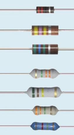
25 13. A resists flow of electricity. Their Ohm values are color banded on to them. Pg. 278 Transistors Resistors Capacitors
26

27


28 14. Resistors can be either fixed or. Pg. 280 Variable Hydraulic Centrifugal


29 15. A stores an electrical charge. Transistor Rectifier Capacitor Pg. 280
30 Capacitor


31 16. A is a one way flow control device for electrical current. They can be compared to fluid system one way check valves. Transistor Diode Capacitor Pg. 283
 Pg.")
32 17. Diodes also perform a function by not allowing flow through them until a certain voltage is reached. (.4 to.7 volts for a Si diode) Pg. 283 Switching Energizing Shorting

33 .4 to.7 Voltage Drop Turn on Voltage OL = Out of Limits

34 18. Diodes are also used to convert or change to, this is known as rectification that s why diodes are sometimes called rectifiers. AC to DC DC to AC RC to 7 UP AC Input DC Output Pg. 284


35 19. A diode or LED produces a colored light when forward biased. Light Emitting Dark Emitting Bark Emitting Pg. 285


36 20. are solid state switches this means they have no moving parts at all! Pg. 286 Transistors Diodes Capacitors


 Collector")
37 21. Transistors have 3 legs or connections: (E), (B), & (C) Collector Base Emitter Pg. 286


38 22. & protect circuits from excessive current flow. Relays & Transformer Coils Fuses & Circuit Breakers Capacitors & Rectifier Bridges Pg. 290


39
40 23. Solderless are ideal for building& testing electronic circuits. Pg. 290 Building & Testing is known as prototyping.


41
42 24. Be able to identify these electrical schematic symbols in lab, on quizzes & tests.
43 24. Be able to identify these electrical schematic symbols in lab, on quizzes & tests.
44 24. Be able to identify these electrical schematic symbols in lab, on quizzes & tests.
45 24. Be able to identify these electrical schematic symbols in lab, on quizzes & tests.
46 24. Be able to identify these electrical schematic symbols in lab, on quizzes & tests.
47 Try identifying these electrical schematic symbols now
48 Try identifying these electrical schematic symbols now
49 Try identifying these electrical schematic symbols now
50 Important Concepts, Definitions & Terms to Know TOP CRISS Main Ideas 2 Column Notes Supporting Details Class Notes & Priority Items to Know for Tests


51 Important Concepts, Definitions & Terms to Know TOP CRISS Highlight Your Study Guides Before Tests Class Notes & Priority Items to Know for Tests

52 Important Concepts, Definitions & Terms to Know TOP CRISS Read 3 Times Class Notes & Priority Items to Know for Tests

53 Important Concepts, Definitions & Terms to Know TOP CRISS Ask Yourself These Questions Class Notes & Priority Items to Know for Tests
54 Systems have Inputs & Outputs A load is an output device in a circuit Resistors can be fixed or variable Capacitors store electricity Diodes block flow in one direction Transistors are if:then solid state switches Fuses protect against excessive current flow Circuit Breakers are resettable protection
DECEMBER 2014 Level 2 Certificate/Diploma in Engineering (IVQ) Principles of electrical and electronics technology
 Principles of electrical and electronics technology") *28502561214* 2850-256 DECEMBER 2014 Level 2 Certificate/Diploma in Engineering (IVQ) Principles of electrical and electronics technology Tuesday 11 December 2014 09:30 11:30 You should have the following
*28502561214* 2850-256 DECEMBER 2014 Level 2 Certificate/Diploma in Engineering (IVQ) Principles of electrical and electronics technology Tuesday 11 December 2014 09:30 11:30 You should have the following
GCSE Electronics. Scheme of Work
 GCSE Electronics Scheme of Work Week Topic Detail Notes 1 Practical skills assemble a circuit using a diagram recognize a component from its physical appearance (This is a confidence building/motivating
SUBELEMENT T6 Electrical components: semiconductors; circuit diagrams; component functions 4 Exam Questions - 4 Groups
 SUBELEMENT T6 Electrical components: semiconductors; circuit diagrams; component functions 4 Exam Questions - 4 Groups 1 T6A Electrical components: fixed and variable resistors; capacitors and inductors;
Laboratory 7 (drawn from lab text by Alciatore) Transistor and Photoelectric Circuits
 Transistor and Photoelectric Circuits") Laboratory 7 (drawn from lab text by Alciatore) Transistor and Photoelectric Circuits Required Components: 1x 330 resistor 2x 1 k resistors 1x 10k resistor 1x 2N3904 small signal transistor 1x TIP31C power
Laboratory 7 (drawn from lab text by Alciatore) Transistor and Photoelectric Circuits Required Components: 1x 330 resistor 2x 1 k resistors 1x 10k resistor 1x 2N3904 small signal transistor 1x TIP31C power
 Code No: M0326 /R07 Set No. 1 1. Define Mechatronics and explain the application of Mechatronics in CNC Machine tools and Computer Integrated Manufacturing (CIM). 2. (a) What are the various Filters that
Demonstrate knowledge of electronic components and their application in the automotive industry
 Page 1 of 5 Demonstrate knowledge of electronic components and their application in the automotive industry Level 3 Credits 5 Purpose This theory-based unit standard is for people in the automotive repair
Applications of diodes
 Applications of diodes Learners should be able to: (a) describe the I V characteristics of a silicon diode (b) describe the use of diodes for component protection in DC circuits and half-wave rectification
High Current MOSFET Toggle Switch with Debounced Push Button
 Set/Reset Flip Flop This is an example of a set/reset flip flop using discrete components. When power is applied, only one of the transistors will conduct causing the other to remain off. The conducting
Electricity and Electronics Training System - Module 1 and 2
 Electricity and Electronics Training System - Module 1 and 2 LabVolt Series Datasheet Festo Didactic en 03/2018 Table of Contents General Description 2 List of Manuals 2 Table of Contents of the Manual(s)
Low Voltage, High Current Time Delay Circuit
 Low Voltage, High Current Time Delay Circuit In this circuit a LM339 quad voltage comparator is used to generate a time delay and control a high current output at low voltage. Approximatey 5 amps of current
Electromechanical Technology /Electromechanical Engineering Technology CIP Task Grid
 1 Secondary Task List 100 DEMONSTRATE KNOWLEDGE OF TECHNICAL REPORTS 101 Identify components of technical reports. 102 Demonstrate knowledge of the common components of technical documents. 103 Maintain
EXPERIMENT 7: DIODE CHARACTERISTICS AND CIRCUITS 10/24/10
 DIODE CHARACTERISTICS AND CIRCUITS EXPERIMENT 7: DIODE CHARACTERISTICS AND CIRCUITS 10/24/10 In this experiment we will measure the I vs V characteristics of Si, Ge, and Zener p-n junction diodes, and
Conventional transistor overview and special transistors
 Conventional transistor overview and special transistors This worksheet and all related files are licensed under the Creative Commons Attribution License, version 1.0. To view a copy of this license, visit
ELECTRONICS AND ELECTRICITY
 INTRODUCTION ELECTRONICS ND ELECTRICITY The science of Electronics and Electricity makes a very important contribution to our everyday existence. Electricity is concerned with the generation, transmission
Paper number: Principles of electrical and electronics technology Paper series: December Practice
 Paper number: 850-56 Paper series: December 04 Question Syllabus reference Question 0.0 a) i) Tesla. ii) Newton. iii) Henry. Marks mark each 4 0.0 0.0 0.0 i) Megavolt ii) Microvolt. a) Directly Inversely
ENGINEERING. Unit 5 Electrical and electronic design Suite. Cambridge TECHNICALS LEVEL 3
 2016 Suite Cambridge TECHNICALS LEVEL 3 ENGINEERING Unit 5 Electrical and electronic design Y/506/7271 Guided learning hours: 60 VERSION 4 - June 2017 black line indicates updated content ocr.org.uk/engineering
5v AC R. 12v. 1kohm. F=35KHz oscilloscope. 3 Final Project OFF. ON Toggle Switch. Relay 5v 2N3906 2N uF LM311. IR Detector +5v GND LED PNP NPN
 3 Final Project Diode 103 IR Detector OFF ON Toggle Switch IR Detector +5v Push Button IR 100uF LED + GND LDR C Preset R 7805 IN GND OUT Relay 5v + PNP 2N3906 1 Kohm NPN 2N3904 4 3 2 1 555 5 6 7 8 4 3
Curriculum. Technology Education ELECTRONICS
 Curriculum Technology Education ELECTRONICS Supports Academic Learning Expectation # 3 Students and graduates of Ledyard High School will employ problem-solving skills effectively Approved by Instructional
ANSWERS AND MARK SCHEMES. (a) A base 1 B collector 1 C emitter 1. (b) = 2.82 ma 1. (c) Zero or very low current 1
 A base 1 B collector 1 C emitter 1. (b) = 2.82 ma 1. (c) Zero or very low current 1") QUESTIONSHEET 1 (a) A base 1 B collector 1 C emitter 1 (b) 0.12 + 2.7 1 = 2.82 ma 1 (c) Zero or very low current 1 QUESTIONSHEET 2 (a) TOTAL / 6 Thermistor in place 1 Thermistor symbol correct 1 Fixed
QUESTIONSHEET 1 (a) A base 1 B collector 1 C emitter 1 (b) 0.12 + 2.7 1 = 2.82 ma 1 (c) Zero or very low current 1 QUESTIONSHEET 2 (a) TOTAL / 6 Thermistor in place 1 Thermistor symbol correct 1 Fixed
Home Map Projects Construction Soldering Study Components 555 Symbols FAQ Links
 Home Map Projects Construction Soldering Study Components 555 Symbols FAQ Links Circuit Symbols Wires Supplies Output devices Switches Resistors Capacitors Diodes Transistors Audio & Radio Meters Sensors
CHAPTER SEMI-CONDUCTING DEVICES QUESTION & PROBLEM SOLUTIONS
 Solutions--Ch. 15 (Semi-conducting Devices) CHAPTER 15 -- SEMI-CONDUCTING DEVICES QUESTION & PROBLEM SOLUTIONS 15.1) What is the difference between a conductor and a semi-conductor? Solution: A conductor
Auto Diagnosis Test #2 Review
 Auto Diagnosis Test #2 Review Your own hand written notes may be used for the 1 st 10 minutes of the test For the Most Effective Personal Review, Look Over the On Line Study Guide Multimedia Based on Chapters
Contents. Acknowledgments. About the Author
 Contents Figures Tables Preface xi vii xiii Acknowledgments About the Author xv xvii Chapter 1. Basic Mathematics 1 Addition 1 Subtraction 2 Multiplication 2 Division 3 Exponents 3 Equations 5 Subscripts
Technician Licensing Class T6
 Technician Licensing Class T6 Amateur Radio Course Monroe EMS Building Monroe, Utah January 11/18, 2014 January 22, 2014 Testing Session Valid dates: July 1, 2010 June 30, 2014 Amateur Radio Technician
CRN: MET-487 Instrumentation and Automatic Control June 28, 2010 August 5, 2010 Professor Paul Lin
 CRN: 32030 MET-487 Instrumentation and Automatic Control June 28, 2010 August 5, 2010 Professor Paul Lin Course Description: Class 2, Lab 2, Cr. 3, Junior class standing and 216 Instrumentation for pressure,
E X A M I N A T I O N S C O U N C I L SECONDARY EDUCATION CERTIFICATE EXAMINATION ELECTRICAL AND ELECTRONIC TECHNOLOGY TECHNICAL PROFICIENCY
 TEST CODE 01317031/SBA FORM TP 2012069 JUNE 2012 C A R I B B E A N E X A M I N A T I O N S C O U N C I L SECONDARY EDUCATION CERTIFICATE EXAMINATION ELECTRICAL AND ELECTRONIC TECHNOLOGY TECHNICAL PROFICIENCY
MINI ELECTRONIC SIGNALS
 MINI ELECTRONIC SIGNALS MINI ELECTRONIC SIGNALS Purpose of Electronic Signals 2002-07 GENINFO Electronics - Overview - MINI Electronic signals move information much like cars move passengers down the highway.
LM317T Variable Voltage Regulator
 LM317T Variable Voltage Regulator The LM317T is a adjustable 3 terminal positive voltage regulator capable of supplying in excess of 1.5 amps over an output range of 1.25 to 37 volts. The device also has
2. What is the difference between an analogue watch and a digital watch? (2)
") ELECTRONICS HOMEWORK 1 1. Make a table with two columns headed Analogue and Digital. Place the following electronic devices into one of the two columns: (4) 7 segment display, motor, solenoid, bulb, LED,
ELECTRONICS HOMEWORK 1 1. Make a table with two columns headed Analogue and Digital. Place the following electronic devices into one of the two columns: (4) 7 segment display, motor, solenoid, bulb, LED,
SWARM South Western (Ontario) Association of Rocket Modellers
 Association of Rocket Modellers") SWARM South Western (Ontario) Association of Rocket Modellers Transolve MF-20 Launch Control System Introduction The Transolve Multi-Fire 20 (MF-20) is a versatile electronic based launch control system
SWARM South Western (Ontario) Association of Rocket Modellers Transolve MF-20 Launch Control System Introduction The Transolve Multi-Fire 20 (MF-20) is a versatile electronic based launch control system
T6A4. Electrical components; fixed and variable resistors, capacitors, and inductors; fuses, switches, batteries
 Amateur Radio Technician Class Element Course Presentation ti ELEMENT SUB-ELEMENTS Technician Licensing Class Supplement T Electrical/Electronic Components Exam Questions, Groups T - FCC Rules, descriptions
Introduction to Arduino HW Labs
 Introduction to Arduino HW Labs In the next six lab sessions, you ll attach sensors and actuators to your Arduino processor This session provides an overview for the devices LED indicators Text/Sound Output
CARIBBEAN EXAMINATIONS COUNCIL
 CARIBBEAN EXAMINATIONS COUNCIL REPORT ON CANDIDATES WORK IN THE CARIBBEAN ADVANCED PROFICIENCY EXAMINATION MAY/JUNE 2014 ELECTRICAL AND ELECTRONIC TECHNOLOGY Copyright 2014 Caribbean Examinations Council
Home Map Projects Construction Soldering Study Components 555 Symbols FAQ Links
 1 of 7 7/3/2010 10:15 μμ Home Map Projects Construction Soldering Study Components 555 Symbols FAQ Links This page explains the operation of transistors in circuits. Practical matters such as testing,
Course Objectives Upon completion of this course, technicians should understand and be able to apply their knowledge of:
 Advanced Electronics Study Guide 2004 2006 Melior, Inc. Course Objectives Upon completion of this course, technicians should understand and be able to apply their knowledge of: Concepts, applications and
Autonomous Robot Control Circuit
 Autonomous Robot Control Circuit - Theory of Operation - Written by: Colin Mantay Revision 1.07-06-04 Copyright 2004 by Colin Mantay No part of this document may be copied, reproduced, stored electronically,
EXPERIMENT 5 CURRENT AND VOLTAGE CHARACTERISTICS OF BJT
 EXPERIMENT 5 CURRENT AND VOLTAGE CHARACTERISTICS OF BJT 1. OBJECTIVES 1.1 To practice how to test NPN and PNP transistors using multimeter. 1.2 To demonstrate the relationship between collector current
Concepts to be Covered
 Introductory Medical Device Prototyping Analog Circuits Part 2 Semiconductors, http://saliterman.umn.edu/ Department of Biomedical Engineering, University of Minnesota Concepts to be Covered Semiconductors
In-Class Exercises for Lab 2: Input and Output Impedance
 In-Class Exercises for Lab 2: Input and Output Impedance. What is the output resistance of the output device below? Suppose that you want to select an input device with which to measure the voltage produced
ELT 215 Operational Amplifiers (LECTURE) Chapter 5
 Chapter 5") CHAPTER 5 Nonlinear Signal Processing Circuits INTRODUCTION ELT 215 Operational Amplifiers (LECTURE) In this chapter, we shall present several nonlinear circuits using op-amps, which include those situations
CHAPTER 5 Nonlinear Signal Processing Circuits INTRODUCTION ELT 215 Operational Amplifiers (LECTURE) In this chapter, we shall present several nonlinear circuits using op-amps, which include those situations
Lab no. 4 Bipolar Transistor (NPN and PNP)
") Lab no. 4 Bipolar Transistor (NPN and PNP) Transistors are semiconductor devices that enable to control the flow of large current by much smaller current. Bipolar transistor consists of three areas of
Lab no. 4 Bipolar Transistor (NPN and PNP) Transistors are semiconductor devices that enable to control the flow of large current by much smaller current. Bipolar transistor consists of three areas of
Figure 1: Basic Relationships for a Comparator. For example: Figure 2: Example of Basic Relationships for a Comparator
 Cornerstone Electronics Technology and Robotics I Week 16 Voltage Comparators Administration: o Prayer Robot Building for Beginners, Chapter 15, Voltage Comparators: o Review of Sandwich s Circuit: To
FCC Technician License Course
 FCC Technician License Course 2014-2018 FCC Element 2 Technician Class Question Pool Presented by: Tamiami Amateur Radio Club (TARC) WELCOME To the SECOND of 4, 3-hour classes presented by TARC to prepare
Lab 2 Revisited Exercise
 Lab 2 Revisited Exercise +15V 100k 1K 2N2222 Wire up led display Note the ground leads LED orientation 6.091 IAP 2008 Lecture 3 1 Comparator, Oscillator +5 +15 1k 2 V- 7 6 Vin 3 V+ 4 V o Notice that power
120 VAC. 12 VAC center-tapped
 INST 200 (Introduction to Instrumentation), Review Exam MASTERY NAME: # Question type 1st attempt 2nd attempt 1 Circuit sketching 2-3 DC circuits 4-5 Mathematics 6 Circuit fault analysis 7-8 AC and opamp
c) Input and output terminals of CB configuration (2Marks)
 Input and output terminals of CB configuration (2Marks)") Subject Code : 17302 Important Instructions to examiners: 1) The answers should be examined by key words and not as word-to-word as given in the model answer scheme. 2) The model answer and the answer
Subject Code : 17302 Important Instructions to examiners: 1) The answers should be examined by key words and not as word-to-word as given in the model answer scheme. 2) The model answer and the answer
Phy 335, Unit 4 Transistors and transistor circuits (part one)
") Mini-lecture topics (multiple lectures): Phy 335, Unit 4 Transistors and transistor circuits (part one) p-n junctions re-visited How does a bipolar transistor works; analogy with a valve Basic circuit
Mini-lecture topics (multiple lectures): Phy 335, Unit 4 Transistors and transistor circuits (part one) p-n junctions re-visited How does a bipolar transistor works; analogy with a valve Basic circuit
+ 24V 3.3K - 1.5M. figure 01
 ELECTRICITY ASSESSMENT 35 questions Revised: 08 Jul 2013 1. Which of the wire sizes listed below results in the least voltage drop in a circuit carrying 10 amps: a. 16 AWG b. 14 AWG c. 18 AWG d. 250 kcmil
ELEXBO A-Car-Engineering
 1 Task: -Construct successively all schematic diagrams and describe your findings. -Describe also the differences between the previous electrical diagram. Construct this electrical circuit and describe
Laboratory 6 Diodes and Transistors
 Laboratory 6 page 1 of 6 Laboratory 6 Diodes and Transistors Introduction In this lab, you will build and test circuits using diodes and transistors. You will use a number of different types of diodes,
Electronics Laboratory And Students kits For Self-Study And Distant Learning. By: Charbel T. Fahed
 Electronics Laboratory And Students kits For Self-Study And Distant Learning By: Charbel T. Fahed Table of Contents I. DC and AC fundamentals 1) Color Code 2) Ohm s Law 3) Series Circuits 4) Parallel Circuits
Federal Urdu University of Arts, Science & Technology Islamabad Pakistan SECOND SEMESTER ELECTRONICS - I
 SECOND SEMESTER ELECTRONICS - I BASIC ELECTRICAL & ELECTRONICS LAB DEPARTMENT OF ELECTRICAL ENGINEERING Prepared By: Checked By: Approved By: Engr. Yousaf Hameed Engr. M.Nasim Khan Dr.Noman Jafri Lecturer
ELECTRICITY AND ELECTRONICS
 ELECTRICITY AND ELECTRONICS (Maximum Marks: 100) (Time allowed: Three hours) (Candidates are allowed additional 15 minutes for only reading the paper. They must NOT start writing during this time.) Answer
DLVP A OPERATOR S MANUAL
 DLVP-50-300-3000A OPERATOR S MANUAL DYNALOAD DIVISION 36 NEWBURGH RD. HACKETTSTOWN, NJ 07840 PHONE (908) 850-5088 FAX (908) 908-0679 TABLE OF CONTENTS INTRODUCTION...3 SPECIFICATIONS...5 MODE SELECTOR
Wisconsin Technical College System Curriculum Standards Model & Program Design Summary ELECTRICAL & INSTRUMENTATION APPRENTICE
 Curriculum Standards Model & Program Design Summary 50-414-2 ELECTRICAL & INSTRUMENTATION APPRENTICE Program Information Program Electrical & Instrumentation Technicians install, service, troubleshoot;
ELECTRONIC FUNDAMENTALS
 Part 66 Cat. B1 Module 4 ELECTRONIC FUNDAMENTALS Vilnius-2017 Issue 1. Effective date 2017-02-28 FOR TRAINING PURPOSES ONLY Page 1 of 67 Figure 1-4. Standard diode color code system Color Digit Diode suffix
HEATHKIT ELECTRONIC KEYER HD-10
 HEATHKIT ELECTRONIC KEYER HD-10 CIRCUIT DESCRIPTION SCHEMATIC DIAGRAM The letter-number designations on the Schematic Diagram are used to identify resistors, capacitors and diodes. Each designation is
INSTRUCTOR S COURSE REQUIREMENTS
 INSTRUCTOR S COURSE REQUIREMENTS PO Box 1189 1042 W. Hamlet Avenue Hamlet, NC 28345 (910) 410-1700 www.richmondcc.edu COURSE: ELN 131 Analog Electronics I SEMESTER & YEAR: SPRING 2015 INSTRUCTOR S NAME
C A R I B B E A N E X A M I N A T I O N S C O U N C I L MAY/JUNE 2013 ELECTRICAL AND ELECTRONIC TECHNOLOGY TECHNICAL PROFICIENCY EXAMINATION
 C A R I B B E A N E X A M I N A T I O N S C O U N C I L REPORT ON CANDIDATES WORK IN THE CARIBBEAN SECONDARY EDUCATION CERTIFICATE EXAMINATION MAY/JUNE 2013 ELECTRICAL AND ELECTRONIC TECHNOLOGY TECHNICAL
Parallel Port Relay Interface
 Parallel Port Relay Interface Below are three examples of controlling a relay from the PC's parallel printer port (LPT1 or LPT2). Figure A shows a solid state relay controlled by one of the parallel port
Carleton University. Faculty of Engineering and Design, Department of Electronics. ELEC 2507 Electronic - I Summer Term 2017
 Carleton University Faculty of Engineering and Design, Department of Electronics Instructors: ELEC 2507 Electronic - I Summer Term 2017 Name Section Office Email Prof. Q. J. Zhang Section A 4148 ME qjz@doe.carleton.ca
Module 04.(B1) Electronic Fundamentals
 Electronic Fundamentals") 1.1a. Semiconductors - Diodes. Module 04.(B1) Electronic Fundamentals Question Number. 1. What gives the colour of an LED?. Option A. The active element. Option B. The plastic it is encased in. Option
1.1a. Semiconductors - Diodes. Module 04.(B1) Electronic Fundamentals Question Number. 1. What gives the colour of an LED?. Option A. The active element. Option B. The plastic it is encased in. Option
Objective Type Questions 1. Why pure semiconductors are insulators at 0 o K? 2. What is effect of temperature on barrier voltage? 3.
 Objective Type Questions 1. Why pure semiconductors are insulators at 0 o K? 2. What is effect of temperature on barrier voltage? 3. What is difference between electron and hole? 4. Why electrons have
Take for instance this circuit:
 Ladder diagrams Ladder diagrams are specialized schematics commonly used to document industrial control logic systems. They are called "ladder" diagrams because they resemble a ladder, with two vertical
Administrative-Master Syllabus form approved June/2006 revised Page 1 of 1
 revised 11-02-06 Page 1 of 1 Administrative - Master Syllabus I. Topical Outline Each offering of this course must include the following topics (be sure to include information regarding lab, practicum,
MULTIMETER TRAINING UNIT QUICKSTART GUIDE
 MULTIMETER TRAINING UNIT QUICKSTART GUIDE MULTIMETER TRAINING UNIT 1 MULTIMETER TRAINING UNIT CONTENTS General Information... 2 Battery... 3 Voltage Drop... 4 Alternator... 5 Frequency... 6 Millivolts...
Exercise 2: Source and Sink Current
 Digital Logic Fundamentals Tri-State Output Exercise 2: Source and Sink Current EXERCISE OBJECTIVE When you have completed this exercise, you will be able to demonstrate how a tri-state buffer output can
Implementation Of Solid State Relays For Power System Protection
 Implementation Of Solid State Relays For Power System Protection Nidhi Verma, Kartik Gupta, Sheila Mahapatra ABSTRACT: This paper provides the implementation of solid state relays for enhancement of power
Physics 364, Fall 2014, Lab #12 (transistors I: emitter follower) Monday, October 13 (section 401); Tuesday, October 14 (section 402)
 Monday, October 13 (section 401); Tuesday, October 14 (section 402)") Physics 364, Fall 2014, Lab #12 Name: (transistors I: emitter follower) Monday, October 13 (section 401); Tuesday, October 14 (section 402) Course materials and schedule are at positron.hep.upenn.edu/p364
Physics 364, Fall 2014, Lab #12 Name: (transistors I: emitter follower) Monday, October 13 (section 401); Tuesday, October 14 (section 402) Course materials and schedule are at positron.hep.upenn.edu/p364
Common Sensors. Understand the following sensors: Pull Up sensor Pull Down sensor Potentiometer Thermistor
 Common Sensors Understand the following sensors: Pull Up sensor Pull Down sensor Potentiometer Thermistor Pull Up Switch (sensor) VERY low current 12 volt Pull Up Switch (sensor) VERY low current 12 volt
Basic Electrical Training
 Basic Electrical Training Electricians Tools Explain how various hand tools are used by an electrician Discuss the safe use of hand tools and power tools Perform basic calculations and measurement conversions
Unit/Standard Number. LEA Task # Alignment
 1 Secondary Competency Task List 100 SAFETY 101 Demonstrate an understanding of State and School safety regulations. 102 Practice safety techniques for electronics work. 103 Demonstrate an understanding
ELECTRONICS An Introduction
 BHAGAVATULA CHARITABLE TRUST ELECTRONICS An Introduction ఎల - ప చయ BCT-RHS BCT Farm Complex Haripuram Rambilli Mandal Visakhapatnam, AP 531061 Phone +91 (8924) 253 770 Fax +91 (8924) 253 780 Author: Sriram
Revised April Unit/Standard Number. Proficiency Level Achieved: (X) Indicates Competency Achieved to Industry Proficiency Level
 Indicates Competency Achieved to Industry Proficiency Level") Unit/Standard Number Electrical, Electronic and Communications Engineering Technology/Technician CIP 15.0303 Task Grid Secondary Competency Task List 100 SAFETY 101 Demonstrate an understanding of state,
Unit/Standard Number Electrical, Electronic and Communications Engineering Technology/Technician CIP 15.0303 Task Grid Secondary Competency Task List 100 SAFETY 101 Demonstrate an understanding of state,
Exercise 1: Tri-State Buffer Output Control
 Exercise 1: Tri-State Buffer Output Control EXERCISE OBJECTIVE When you have completed this exercise, you will be able to demonstrate how the enable and data inputs control the output state of a tri-state
Diodes. Analog Electronics Lesson 4. Objectives and Overview:
 Analog Electronics Lesson 4 Diodes Objectives and Overview: This lesson will introduce p- and n-type material, how they form a junction that rectifies current, and familiarize you with basic p-n junction
Laboratory Four - Bipolar Junction Transistor (BJT)
") M/IS 3512 ioelectronics Laboratory Four - ipolar Junction Transistor (JT) Learning Objectives: Know how to differentiate between PNP & NPN JT transistors using a multimeter. e familiar with the operation
M/IS 3512 ioelectronics Laboratory Four - ipolar Junction Transistor (JT) Learning Objectives: Know how to differentiate between PNP & NPN JT transistors using a multimeter. e familiar with the operation
Transistors and Applications
 Chapter 17 Transistors and Applications DC Operation of Bipolar Junction Transistors (BJTs) The bipolar junction transistor (BJT) is constructed with three doped semiconductor regions separated by two
WESTERN IOWA TECH COMMUNITY COLLEGE. Course Syllabus. Electrical Technician Level 2
 Course Title: Electrical Technician Level Total Hours:56 Meeting time/ location :TBA Instructor: Chris Sewalson Phone:712-274-8733 ext1407 E-mail Chris.sewalson@witcc.edu Office Location: Lemars Center
ECET 211 Electric Machines & Controls Lecture 7 Relays (1 of 2) Lecture 7 Relays
 Lecture 7 Relays") ECET 211 Electric Machines & Controls Lecture 7 Relays (1 of 2) Text Book: Electric Motors and Control Systems, by Frank D. Petruzella, published by McGraw Hill, 2015 Paul I-Hai Lin, Professor of Electrical
ECET 211 Electric Machines & Controls Lecture 7 Relays (1 of 2) Text Book: Electric Motors and Control Systems, by Frank D. Petruzella, published by McGraw Hill, 2015 Paul I-Hai Lin, Professor of Electrical
ENGINEERING. Unit 4 Electrical, electronic engineering operations and application Suite. Cambridge TECHNICALS LEVEL 2
 2016 Suite Cambridge TECHNICALS LEVEL 2 ENGINEERING Unit 4 Electrical, electronic engineering operations and L/615/2134 Guided learning hours: 60 Version 1 September 2016 ocr.org.uk/engineering LEVEL 2
MAHARASHTRA STATE BOARD OF TECHNICAL EDUCATION
 Important Instructions to examiners: 1) The answers should be examined by key words and not as word-to-word as given in the model answer scheme. 2) The model answer and the answer written by candidate
Chapter 5: Diodes. I. Theory. Chapter 5: Diodes
 Chapter 5: Diodes This week we will explore another new passive circuit element, the diode. We will also explore some diode applications including conversion of an AC signal into a signal that never changes
Perkins Statewide Articulation Agreement. Documentation item: Secondary Competency Task List Coversheet
 Perkins Statewide Articulation Agreement Documentation item: Secondary Task List Coversheet The Secondary School agrees to: A. Implement the approved PDE Program(s) of Study. B. Provide assessment of student
S11 Adjustable Speed Drive Engineering Specification
 PART 1 - GENERAL 1.0 Scope This specification shall cover Toshiba S11 AC Variable Frequency Drives, 6 pulse for 3- phase 200-240VAC, 380-500VAC and single phase 200V to 240VAC. 1.1 References A. National
Maintenance Manual INTERNAL BATTERY STANDBY CHARGER OPTION BC01 (9669), 9670 AND 9771 (FOR MASTR II STATIONS) Mobile Communications LBI-30869L
, 9670 AND 9771 (FOR MASTR II STATIONS) Mobile Communications LBI-30869L") L Mobile Communications INTERNAL BATTERY STANDBY CHARGER OPTION BC01 (9669), 9670 AND 9771 (FOR MASTR II STATIONS) Printed in U.S.A. Maintenance Manual TABLE OF CONTENTS Page DESCRIPTION...................................................
L Mobile Communications INTERNAL BATTERY STANDBY CHARGER OPTION BC01 (9669), 9670 AND 9771 (FOR MASTR II STATIONS) Printed in U.S.A. Maintenance Manual TABLE OF CONTENTS Page DESCRIPTION...................................................
4/30/2012. General Class Element 3 Course Presentation. Practical Circuits. Practical Circuits. Subelement G7. 2 Exam Questions, 2 Groups
 General Class Element 3 Course Presentation ti ELEMENT 3 SUB ELEMENTS General Licensing Class Subelement G7 2 Exam Questions, 2 Groups G1 Commission s Rules G2 Operating Procedures G3 Radio Wave Propagation
Physics 281 EXPERIMENT 7 I-V Curves of Non linear Device
 Physics 281 EXPERIMENT 7 I-V Curves of Non linear Device Print this page to start your lab report (1 copy) Bring a diskette to save your data. OBJECT: To study the method of obtaining the characteristics
(A) im (B) im (C)0.5 im (D) im.
 im (B) im (C)0.5 im (D) im.") Dr. Mahalingam College of Engineering and Technology, Pollachi. (An Autonomous Institution affiliated to Anna University) Regulation 2014 Fourth Semester Electrical and Electronics Engineering 141EE0404
Dr. Mahalingam College of Engineering and Technology, Pollachi. (An Autonomous Institution affiliated to Anna University) Regulation 2014 Fourth Semester Electrical and Electronics Engineering 141EE0404
Prerequisites: Knowledge of Automobile Electrical system being studied in IV semester.
 Course Title: Automobile Electrical & Electronics System lab Course Code: 15AT44P Credits (L:T:P) : 0:2:4 Credit-3 Core/ Elective: Core Type of : Tutorials and Practices Total Contact Hours: 78 CIE- 25
Experiment (1) Principles of Switching
 Principles of Switching") Experiment (1) Principles of Switching Introduction When you use microcontrollers, sometimes you need to control devices that requires more electrical current than a microcontroller can supply; for this,
Experiment (1) Principles of Switching Introduction When you use microcontrollers, sometimes you need to control devices that requires more electrical current than a microcontroller can supply; for this,
charge time Electric Current and Circuits Current HEAT will flow if there is a difference in temperature
 Electric Current and Circuits Electrons will flow if there is a difference in electric pressure. Electric pressure is called Potential, and is measured in Volts. If there is no difference in pressure from
Electronic Fundamentals (Digital and Analogue) (2hours)
 (2hours)") C1.0 ANALOGUE FUNDAMENTALS COMPETITOR S INSTRUCTION:- Attempt all questions: Circle the letter that indicates the correct answer. C1.1 The prefix nano stands for: (a) 106 (b) 103 (c) 10 3 (d) 10 6 (Marks
C1.0 ANALOGUE FUNDAMENTALS COMPETITOR S INSTRUCTION:- Attempt all questions: Circle the letter that indicates the correct answer. C1.1 The prefix nano stands for: (a) 106 (b) 103 (c) 10 3 (d) 10 6 (Marks
SECTION 3 BASIC AUTOMATIC CONTROLS UNIT 12 BASIC ELECTRICITY AND MAGNETISM. Unit Objectives. Unit Objectives 2/29/2012
 SECTION 3 BASIC AUTOMATIC CONTROLS UNIT 12 BASIC ELECTRICITY AND MAGNETISM Unit Objectives Describe the structure of an atom. Identify atoms with a positive charge and atoms with a negative charge. Explain
INPUT: 110/220VAC. Parallel Input Series Input Parallel Output Series Output (W/CT)
") Linear power supply design: To make a simple linear power supply, use a transformer to step down the 120VAC to a lower voltage. Next, send the low voltage AC through a rectifier to make it DC and use a
Linear power supply design: To make a simple linear power supply, use a transformer to step down the 120VAC to a lower voltage. Next, send the low voltage AC through a rectifier to make it DC and use a
Revised April Unit/Standard Number. High School Graduation Years 2016, 2017 and 2018
 Unit/Standard Number High School Graduation Years 2016, 2017 and 2018 Electrical, Electronic and Communications Engineering Technology/Technician CIP 15.0303 Task Grid Secondary Competency Task List 100
Application Note AN-3006 Optically Isolated Phase Controlling Circuit Solution
 www.fairchildsemi.com Application Note AN-3006 Optically Isolated Phase Controlling Circuit Solution Introduction Optocouplers simplify logic isolation from the ac line, power supply transformations, and
Electrical, Electronic and Communications Engineering Technology/Technician CIP Task Grid
 Secondary Task List 100 SAFETY 101 Describe OSHA safety regulations. 102 Identify, select, and demonstrate proper hand tool use for electronics work. 103 Recognize the types and usages of fire extinguishers.
Iec Schematic Symbols For Autocad Electrical
 Iec For Autocad Free PDF ebook Download: Iec For Autocad Download or Read Online ebook iec schematic symbols for autocad electrical in PDF Format From The Best User Guide Database in. The family codes
UNIVERSITY OF NORTH CAROLINA AT CHARLOTTE. Department of Electrical and Computer Engineering
 UNIVERSITY OF NORTH CAROLINA AT CHARLOTTE Department of Electrical and Computer Engineering Experiment No. 2 - Semiconductor Diodes Overview: In this lab session students will investigate I-V characteristics