DIY-990. assembly guide. Hairball Audio, LLC V3.0
|
|
|
- Dana Collins
- 5 years ago
- Views:
Transcription
1 DIY-990 V3.0 assembly guide Hairball Audio, LLC
2 Saftey Precausions Read and understand all of the instructions before assembling this DIY project. Improper assembly could result in damage to your property or serious injuries. Hairball Audio, LLC is not liable for any damage or injury resulting from the assembly or use of this DIY project. Use caution when assembling and testing. Make sure you are using the appropriate tools and following the manufatures safey instructions. Disclaimer of Liability and Warranties The assembly manual for this DIY project is complete and accurate to the best of Hairball Audio, LLC s knowledge and is provided free of charge. Hairball Audio, LLC disclaims any and all liability for injuries or damage resulting from the assembly or use of this DIY project, including any consequential damages. Anyone assembling or using this DIY project does so at their own risk. Hairball Audio, LLC makes no warranty of any kind with respect to the assembly or use of this DIY project and explicitly disclaims any Implied Warranty of Merchantability. Hairball Audio, LLC warrantee coverage insures that parts arrive in working order. Assembly support is not offered or included with this DIY project. By downloading and/or following these plans, the user acknowledges that he or she has read and followed the Assembly Instructions and Safety Precautions Hairball Audio, LLC
3 Inroduction Deane Jensen s now famous JE-990 paper describing the design, testing, and theory behind a powerful ultra low noise operation amplifier, was first introduced in the February 1980 AES journal. The design started with the LM394 dual super matched transistor as the input device. The LM394 is actually a monolithic device consisting of two pairs of 50 transistors connected in parallel to eliminate random variations in the individual devices. In addition to being designed for low noise, the JE-990 is a powerful op-amp capable of adequately driving a 75Ω load. Many commercial versions of the 990 design are available for purchase today. The John Hardy Co JH-990 is certainly the best and most well respected version. Luckily, it s also one of the most affordable. Unfortunately the JH-990 is potted and not very DIY friendly. Many of the other designs available for purchase fall short of the original design an are 990 op-amps in name only. Shortly after the release of the Lola mic pre, I began considering offering a DIY JE-990 that would be affordable, authentic, and easy to build. Or at least as easy as soldering over 30 components on a one inch square PCB can be. Certainly it would need to a 2520 footprint and I would need to source an affordable LM394 substitute. Luckily much of this work had been completed a few years ago by PCB designer MNATs when he designed a DIY JE layout. I contacted MNATs about reworking the PCB for a different input component to replace the discontinued LM394 and he agreed to give a shot. The common replacement for the LM394 is the Analog Devices MAT12. The MAT12 is the successor to the MAT02 and is available in a TO-78 thru-hole package. A very elegant component, but not a cheap one. They can cost $15-$30 depending on quantity. Luckily there is another option. Analog devices also offers the SSM2212 which a dual matched transistor surface mount device (SMD) offering even superior performance specs than the LM394 or MAT12. Even better, it can be purchased for a fraction of the cost of the LM394. The Hairball Audio DIY-990 uses this device. Soldering Guide Soldering WELL is one of those things that seems easy until you try it. With a small PCB such as the DIY-990, good soldering skills are a must. As always, with solder, less is more. Dave Jones of the EEVBlog has created an excellent set of video tutorials. The tutorial is presented in three parts: tools, soldering through hole components, and soldering surface mount components. For our purposes, I recommend you watch part 1 and 2. The videos are lengthy at about 25 minutes each, but they are well worth watching. Even I learned a few things. The videos can be seen by visiting: hairballaudio.com/solder

4 PCB Overview The DIY-990 arrives with several components already installed. The six PCB mounting pins, two 0.1uF SMD bypass capacitors, and the SMD SSM2212 dual surface mount transistor. These componets are mounted on the bottom side of the PCB. The remaining components are all mounted on the top side.


5 Diodes Start by installing the nine 1N914B diodes that are located in the DIODE/TRANSISTORS/ CAPCITORS bag. These diodes, along with the resistors you ll install in the next step, are mounted vertically on the PCB. Note that the cathode side of the diodes are labled with a black stripe. Bend the OPPOSITE lead back towards the body of the diode.

6 Diodes are POLARIZED devices. They must be mounted in the right direction. For the DIY-990 PCB all diodes are mounded so the cathode, the end with the black stripe, meets the side of the component footprint with the circle around the pad. The next page shows where these diodes should be placed. When you re done you should have something that looks like the image below.
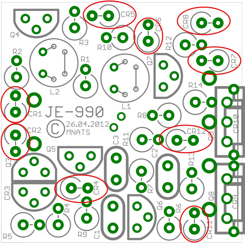
7 Diode Map


8 Resistors Next you ll install the 14 resistors. Check each resistor with a DMM and sort them using the sorting pages at the end of this document. Although the resistors are not polarized, to avoid leads touching and shorting, you should install them so that the body meets the side of the component footprint with the circle around the pad. The next page shows where these resistors should be placed. When you re done you should have something that looks like the image below.

9 Resistor Map * 110Ω * *R10 and R11 are set for 15V/16V operation with resistances of 33K. For 24V operaction use 62K Ω resistors for R10 and R 11.

10 Capacitors Next you ll install the three ceramic caps. These are non-polarized and can be installed in either direction. However, you must install the correct value in the proper place. Two of these values have been changed from the original Jensen paper to accomodate for modern value parts sourcing. The 91pF has been updated to 100pF and the 62pF to 68pF. These small change had no measurable effect. To determine the capacitor values look closely at the capacitor body. On one side you ll see numbers followed by the letter J. The first two numbers set the value, the third sets the multiplier, and the J indicates a 5% tollerence. For the DIY-990 the values are as follows: 68J = 68pF 101J = 100pF 151J = 150pF The next page shows where these capactiors should be placed. When you re done you should have something that looks like the image below.

11 Capcitor Map


12 TO-92 Transistors Next you ll install the TO-92 transistors. There are four PN250A and two PN2484 transistors. You can identify them by looking at the identfication marks on the flat face of the body. CR3, though a diode designation, is actually a PN4250A transistor connected as a diode. This allows us to bond the bodies of CR3 and Q3 for thermal coupling as instructed in the AES paper. Before installing these componets place the supplied shirk wrap tubing over the transistors and shrink it with a heat gun or hair dryer. Be careful not to over heat and damage the transistors. You can add a bit of thermal adhesive if you like.
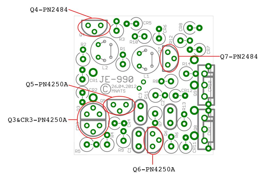
13 Transistor Map

14 Output Transistors and Diodes The TO-220 output transistors (Q8 & Q9) must have 1N914B diodes thermally coupled to their bodies to prevent distortion with low-impedance loads. This is achieved by using the supplied clamp. Looking at the PCB silkscreen you ll see that the cathode (black stripe) should be facing right when viewing the TO-220 trnsistors from the rear (side with metal tab). This is true for both the MJE171 and MJE181. TWO IMPORTANT POINTS!!! 1. These transistors are not the identical. The transistor marked MJE171 is a PNP transistor and needs to be placed in the Q9 footprint and one marked MJE181 in an NPN transistor and needs to be placed in the Q8 footprint. 2. When you clip the diode to the transistor, ensure the diode leads are not touching the clamp or the diode may short accross the metal clamp and not preform its funtion. You can use the transistor body as a jig for bending the diode leads. The bottom edge of the clamp wraps around the diode and extends just past the transistor mounting surface fitting snug to the transistor bottom. Center the clip, which should sit flush to the surface, and use the supplied #2 screw and nut to secure the clamp. You can add a bit of thermal adhesive if you like. The pads for the inner leads of each diode are very close on the PCB and may become bridged with solder or make contact. This is ok, they are connected on the circuit.


15 Note the red circle: The diode leg is clear of the clamp Output Transistor and Diode Map

16 Inductors The two 20uH inductors are often missed in many 990 designs. Included are two Jensen inductors you will wind with the supplied 30 AWG wire as described in the AES paper. Once installed you can add some lacquer or nail polish to the top of the inductor to prevent wire corrsion. Winding is simple, there is no top or bottom side, just six holes in two rows of three. You can start at either end of the two rows, below I have started in the upper right. Cut about 8 of wire from your supplied spool then follow the numbers in order to complete the pattern. Pull the wire through slowly and try to avoing kinking or leaving it too lose. Do not pull too tight, or the wire will break. We ve supplied some extra wire for just in case.


17 Final Thoughts You re done! Congratulations, youve built a JE-990 to the specifications of the famous Jensen AES paper. All that s left is to insert it into you circuit or design a circuit around it. Be sure that the supply voltage is appropriate for the values of R10 and R11.
18 Resistors and Inductors Bag Value Name QTY Value Name QTY 3.9Ω R13,R Ω R1,R2 2 Value Name QTY Value Name QTY 110Ω R Ω R9 1 Value Name QTY Value Name QTY 160Ω R Ω R7 1 Value Name QTY Value Name QTY 300Ω R4,R5,R8 3 2KΩ R6 1 Value Name QTY Value Name QTY 33KΩ R10,R uH L1,L2 2
19 Diodes, Transistors and Capacitors Bag Value Type QTY Value Type QTY 1N194B Diode 9 PN2484 Transistor 2 Value Type QTY Value Type QTY PN4250A Transistors 4 68pF Capacitor 1 Value Type QTY Value Type QTY 100pF Capacitor 1 150pF Capacitor 1
20 Output Transistors, Diodes and Hardware Value Type QTY Value Type QTY MJE171 Transistor 1 MJE181 Transistors 1 Value Type QTY Value Type QTY 1N914B Diode 2 - Clamp 2 Value Type QTY Value Type QTY - #2 Screw 2 - #2 Nut 2 Value Type QTY - Shrink Tube 1
21 Hairball Audio, LLC 6523 California Ave SW PMB 291 Seattle, WA
V6.2 SoftRock Lite Builder s Notes. November 17, 2006
 V6.2 SoftRock Lite Builder s Notes November 17, 2006 Be sure to use a grounded tip soldering iron in building the v6.2 SoftRock circuit board. The soldering iron needs to have a small tip, (0.05-0.1 inch
TS500 Assembly guide. Soldering. TS500 Assembly guide Main PCB 1. Diodes. Document revision 1.2 Last modification : 17/12/16
 TS500 Assembly guide Safety warning The kits are main powered and use potentially lethal voltages. Under no circumstance should someone undertake the realisation of a kit unless he has full knowledge about
SoftRock v6.0 Builder s Notes. May 22, 2006
 SoftRock v6.0 Builder s Notes May 22, 2006 Be sure to use a grounded tip soldering iron in building the v6.0 SoftRock circuit board. The soldering iron needs to have a small tip, (0.05-0.1 inch diameter),
SoftRock v6.0 Builder s Notes. April 6, 2006
 SoftRock v6.0 Builder s Notes April 6, 006 Be sure to use a grounded tip soldering iron in building the v6.0 SoftRock circuit board. The soldering iron needs to have a small tip, (0.05-0. inch diameter),
Manual Version July 2007
 Manual Version 1.2 - July 2007 Page 1 Table of Contents Section1: M3 Phono Board Build...3 Phono Board Parts List...3 Preparation...4 Fitting the Valve Bases...6 Installing the Resistors...7 Starting the
LA502 Assembly guide Main PCB Resistors - (2)
") LA502 Assembly guide Safety warning The kits are main powered and use potentially lethal voltages. Under no circumstance should someone undertake the realisation of a kit unless he has full knowledge about
LA502 Assembly guide Safety warning The kits are main powered and use potentially lethal voltages. Under no circumstance should someone undertake the realisation of a kit unless he has full knowledge about
Read This Page First
 Read This Page First If you are reading this you know the manuals are always available at QRPKITS.com. If you have questions contact qrpkits.com@gmail.com There is no need to print out the whole assembly
Discrete Op-Amp Kit MitchElectronics 2019
 Discrete Op-Amp Kit MitchElectronics 2019 www.mitchelectronics.co.uk CONTENTS Introduction 3 Schematic 4 How It Works 5 Materials 9 Construction 10 Important Information 11 Page 2 INTRODUCTION Even if
DuoDrive Nixie Bargraph Kit
 Assembly Instructions And User Guide Nixie Bargraph Kit - 1 - REVISION HISTORY Issue Date Reason for Issue Number 1 12 December 2017 New document - 2 - 1. INTRODUCTION 1.1 About Nixie Bargraph Driver IN-9
HF SuperPacker Pro 100W Amp Low Pass Filter Module LPF-100 R3B. Construction Manual for Model LPF-100 R3B June 22, 2013
 HF SuperPacker Pro W Amp Low Pass Filter Module LPF- RB Construction Manual for Model LPF- RB June, LPF RB TOP LPF RB BOTTOM The LPF- RB design is electrically the same as RA but has been changed for improved
MICROGRANNY v2.1 - Assembly Guide
 last update: 9. 5. 2017 MICROGRANNY v2.1 - Assembly Guide bastl-instruments.com INTRODUCTION Welcome to the assembly guide for the MicroGranny kit. MicroGranny is a monophonic granular sampler by Bastl
Starving Student II. Starving Student II. SS2 guide. Written By: 6L guides.diyaudio.com/ Page 1 of 24
 SS2 guide Written By: 6L6 2019 guides.diyaudio.com/ Page 1 of 24 INTRODUCTION This is a build guide for the hybrid headphone/pre-amplifier. You can buy a kit at the SSII product listing on the diyaudio
KN-Q10 Assembly Manual
 KN-Q10 Assembly Manual Translated by Adam Rong, BD6CR/4 with permission from Ke Shi, BA6BF Edited by Stephen, VK2RH Revision B, Oct 14, 2010 Thank you for purchasing the KN-Q10 4 Band SSB/CW Dual Mode
Switcher Assembly guide. Switcher Assembly guide 1. Soldering. 2. Switcher3 vs Switcher2. 3. PCB split.
 Safety warning The kits are main powered and use potentially lethal voltages. Under no circumstance should someone undertake the realisation of a kit unless he has full knowledge about safely handling
SpikerBox v1.3 DIY Instructions
 SpikerBox v. DIY Instructions Prepare yourself. In hours, you will have built your own SpikerBox to begin doing neuroscience and whatever your creative mind can conjure. Materials Needed:. A Backyard Brains
STEP 0 Prepare the Materials.
 How to Build a Germanium Fuzz Guitar Effect. This document will guide you to build and test your Germanium Fuzz guitar pedal. With all the materials on hand, it takes around 2-4 hours to build it. Try
SoftRock v5.0 Builder s Notes. December 12, Building a QSD Kit
 SoftRock v5.0 Builder s Notes December 12, 2005 Building a QSD Kit Be sure to use a grounded tip soldering iron in building the QSD board. The soldering iron needs to have a small tip, (0.05-0.1 inch diameter),
IR add-on module circuit board assembly - Jeffrey La Favre January 27, 2015
 IR add-on module circuit board assembly - Jeffrey La Favre January 27, 2015 1 2 For the main circuits of the line following robot you soldered electronic components on a printed circuit board (PCB). The
Value Location Qty Potentiometers C1M Distortion 1 A10k Volume 1. Footswitch 3PDT SW1 1. Jacks 1/4 Mono 2 DC Power 1
 Distortion BUILD INSTRUCTIONS Thank you for your purchase of our Distortion+ kit! We have completely redesigned our entire line of kits to be the most user friendly, while still maintaining their same
Pacific Antenna 20 and 40M Lightweight Dipole Kit
 Pacific Antenna 20 and 40M Lightweight Dipole Kit Antenna diagram showing configuration and lengths when assembled 7 8 16 9 16 9 Description The Pacific Antenna lightweight dual band dipole kit provides
Audio Amplifier. November 27, 2017
 Audio Amplifier November 27, 2017 1 Pre-lab No pre-lab calculations. 2 Introduction In this lab, you will build an audio power amplifier capable of driving a 8 Ω speaker the way it was meant to be driven...
Pacific Antenna 20 and 40M Lightweight Dipole Kit
 Pacific Antenna 20 and 40M Lightweight Dipole Kit Diagram showing configuration and approximate lengths 8 6 16 9 16 9 8 6 Description The Pacific Antenna lightweight dual band, trap dipole kit provides
Build Your Own Clone Li l Echo Kit Instructions
 Build Your Own Clone Li l Echo Kit Instructions Warranty: BYOC, Inc. guarantees that your kit will be complete and that all parts and components will arrive as described, functioning and free of defect.
PAT-4 POWER SUPPLY ASSEMBLY MANUAL Rev B Version
 PAT-4 POWER SUPPLY ASSEMBLY MANUAL Rev B Version 2013 AkitikA, LLC All rights reserved Revision Bp01 November 3, 2013 Page 1 of 16 Table of Contents Table of Contents... 2 Table of Figures... 2 Section
Building the Toothpick Audio CW Filter
 Building the Toothpick Audio CW Filter Introduction The toothpick is a simple variable bandpass audio filter designed to compliment the Splinter QRPp Trans-Receiver. The filter also contains an audio amplifier
Build Your Own Clone Kuzco Jr. Kit Instructions
 Build Your Own Clone Kuzco Jr. Kit Instructions Warranty: BYOC, Inc. guarantees that your kit will be complete and that all parts and components will arrive as described, functioning and free of defect.
Pacific Antenna 20 and 40M Lightweight Dipole Kit
 Pacific Antenna 20 and 40M Lightweight Dipole Kit Diagram showing configuration and approximate lengths 8 3 16 9 16 9 8 3 Description The Pacific Antenna lightweight dual band, trap dipole kit provides
Pacific Antenna Field Strength Indicator Kit
 Pacific Antenna Field Strength Indicator Kit Description The Field Strength Indicator kit from Pacific Antenna provides a visual way to monitor the presence and relative strength RF fields through the
MP573 Assembly guide. Soldering. MP573 Assembly guide PCB split PCB split. Document revision 2.2 Last modification : 22/08/17
 MP573 Assembly guide Safety warning The kits are main powered and use potentially lethal voltages. Under no circumstance should someone undertake the realisation of a kit unless he has full knowledge about
Build Your Own Clone Li l Reverb Kit Instructions
 Build Your Own Clone Li l Reverb Kit Instructions Warranty: BYOC, Inc. guarantees that your kit will be complete and that all parts and components will arrive as described, functioning and free of defect.
RF Current Meter Kit
 Kit When assembled, this kit provides you with a simple but effective means of measuring the current in antenna wires, and of looking for braid currents on coax feeders. The more current you can get flowing
Build Your Own Clone Li l Analog Chorus Kit Instructions
 Build Your Own Clone Li l Analog Chorus Kit Instructions Warranty: BYOC, Inc. guarantees that your kit will be complete and that all parts and components will arrive as described, functioning and free
Read This Page First
 Read This Page First If you are reading this you know the manuals are always available at QRPKITS.com. This is version 8.0 of the manual dated 4/27/2016. There is no need to print out the whole assembly
Penrose Quantizer Assembly Guide
 Penrose Quantizer Assembly Guide Schematic and BOM The schematic can be found here: www.sonic-potions.com/public/penrosequantizerschematic.pdf The BOM is available at google docs: Link to BOM Prepare the
LDB-1 Kit Instructions Page 1 of 8
 LDB-1 Kit Instructions Page 1 of 8 Important Information Congratulations and thank you for your purchase of the LDB-1 Little Drummer Boy Analog Drum Machine Kit! Before you start, please read the enclosed
Mini Evaluation Board for Filterless Class-D Audio Amplifier EVAL-SSM2301-MINI
 Mini Evaluation Board for Filterless Class-D Audio Amplifier EVAL-SSM30-MINI FEATURES DC power supply accepts.5 V to 5.5 V Single-ended and differential input capability Extremely small board size allows
Elektor Construction Guide TAPIR
 Elektor Construction Guide TAPIR The TAPIR is a three-dimensional assembly. To ensure good access to all soldering points, we recommend assembling the kit exactly according to the described sequence. 1
Wiring Manual NEScaf April 2010 (August 2006)
") Wiring Manual NEScaf April 2010 (August 2006) Switched Capacitor Audio Filter The NEScaf is a switched capacitor audio filter (acronym SCAF) built around a building-block type filter chip. The NEScaf will
Wiring Manual NEScaf April 2010 (August 2006) Switched Capacitor Audio Filter The NEScaf is a switched capacitor audio filter (acronym SCAF) built around a building-block type filter chip. The NEScaf will
Bill of Materials: General Purpose Alarm, Pulsed PART NO
 General Purpose Alarm, Pulsed PART NO. 2190207 I hate alarms that sound continuously - unless they are smoke alarms. Smoke alarms should be annoying, but others should not. I wanted an alarm for a function
ILER-40 AGC "ADD-ON" MINI-MODULE Last review November 1, 2012
 ILER-40 AGC "ADD-ON" MINI-MODULE Last review November 1, 2012 ea3gcy@gmail.com Latest updates and news: www.qsl.net/ea3gcy PLEASE READ ALL INSTRUCTIONS COMPLETELY AT LEAST ONCE BEFORE STARTING. Installation
LED Field Strength Indicator Kit
 LED Field Strength Indicator Kit Description The Field Strength Indicator kit from Qrpkits.com provides a visual way to monitor RF fields through the brightness of an LED. It will respond to RF fields
Workshop Part Identification Lecture N I A G A R A C O L L E G E T E C H N O L O G Y D E P T.
 Workshop Part Identification Lecture N I A G A R A C O L L E G E T E C H N O L O G Y D E P T. Identifying Resistors Resistors can be either fixed or variable. The variable kind are called potentiometers
Construction notes for the symmetrical 400 watt amplifier
 Construction notes for the symmetrical 400 watt amplifier Introduction The symmetrical amplifier is an update of one of my designs, which appeared in the Australian electronics magazine Silicon Chip in
Build Your Own Clone 27V Boost Kit Instructions
 Build Your Own Clone 27V Boost Kit Instructions Warranty: BYOC, Inc. guarantees that your kit will be complete and that all parts and components will arrive as described, functioning and free of defect.
Music Thing Modular SimpleEQ Construction Guide (1206 version)
") Music Thing Modular SimpleEQ Construction Guide (1206 version) Page 1 Useful Links The latest version of this doc and BOM can always be found at http://thonk.co.uk/documents/eq/ A build thread on the Muffwiggler
Music Thing Modular SimpleEQ Construction Guide (1206 version) Page 1 Useful Links The latest version of this doc and BOM can always be found at http://thonk.co.uk/documents/eq/ A build thread on the Muffwiggler
The Switched Longwire Tuner SLT
 The Switched Longwire Tuner SLT Thank you for purchasing the SLT kit from Hendricks QRP Kits. This kit is a very high quality kit that you will find easy to build, yet when you finish, you will have a
TekBot Remote Control Receiver Board Construction
 TekBot Remote Control Receiver Board Construction Purpose This tutorial illustrates the procedure for construction of the Receiver board for the TekBot. A Guide to Soldering Many of you have soldered once
Read This Page First
 Pacific Antenna 0 Watt HF Amplifier Kit Manual This is Version 5.5 dated 060505 Read This Page First If you are reading this you know the manuals are always available at QRPKITS.com. If you have questions
Pacific Antenna Wall Wart Tamer 2.0 Kit
 Pacific Antenna Wall Wart Tamer 2.0 Kit Description The Wall Wart Tamer lets you utilize those surplus computer and wall pack power supplies as a clean, adjustable voltage, DC power source for radios and
Build Your Own Clone Li l Comp Kit Instructions
 Build Your Own Clone Li l Comp Kit Instructions Warranty: BYOC, Inc. guarantees that your kit will be complete and that all parts and components will arrive as described, functioning and free of defect.
Build Your Own Clone Li l Beaver (Ram s Head) Kit Instructions
 Kit Instructions") Build Your Own Clone Li l Beaver (Ram s Head) Kit Instructions Warranty: BYOC, Inc. guarantees that your kit will be complete and that all parts and components will arrive as described, functioning and
Build Your Own Clone Li l Beaver (Ram s Head) Kit Instructions Warranty: BYOC, Inc. guarantees that your kit will be complete and that all parts and components will arrive as described, functioning and
PM24 Installation Instructions
 Marchand Electronics Inc. PO Box 473, Webster, NY 14580 Tel:(716) 872-0980 Fax:(716) 872-1960 info@marchandelec.com http://www.marchandelec.com (c)1997 Marchand Electronics Inc. PM24 Installation Instructions
Pacific Antenna Easy SWR Indicator Kit
 Pacific Antenna Easy SWR Indicator Kit Description Monitoring the match of an antenna to your transmitter or adjusting an antenna tuner for best match requires an indicator of the reflected power as an
HT-1A Dual Band CW QRP Transceiver. Kit Building Instructions
 HT-A Dual Band CW QRP Transceiver Kit Building Instructions Rev B, July 8, 08 Designed by BD4RG Exclusively distributed by CRKITS.COM and its worldwide distributors Join the group http://groups.io/g/crkits
Build Guide CascadiA. GeFet Preamp
 Build Guide CascadiA GeFet Preamp Disclaimery stuff: This project is meant to be assembled by fellow DIYers from the Madbean forum and should only be used for the forces of good. Any other uses prohibited
DIODE / TRANSISTOR TESTER KIT
 DIODE / TRANSISTOR TESTER KIT MODEL DT-100K Assembly and Instruction Manual Elenco Electronics, Inc. Copyright 1988 Elenco Electronics, Inc. Revised 2002 REV-K 753110 DT-100 PARTS LIST If you are a student,
Pacific Antenna - Easy TR Switch
 Pacific Antenna - Easy TR Switch Kit Description The Easy TR Switch is an RF sensing switch that can be used to switch an antenna between a receiver and transmitter. It also has a second switched pair
& ' (wire, inches) 16 black Tef-Flex 16 Black Lex 32 Red Lex 48 Blue Tef-Flex 32 White Tef-Flex
 16 black Tef-Flex 16 Black Lex 32 Red Lex 48 Blue Tef-Flex 32 White Tef-Flex") ! " # $! " % Qty Part (woofer) 1 4.40mH 16 AWG inductor 1 10.0uF Yellow film capacitor 1 5.62 Ohm NORTH resistor (tweeter) 1 8uF Yellow film capacitor 1 0.56mH 16 AWG inductor 1 3.32 Ohm NORTH resistor
! " # $! " % Qty Part (woofer) 1 4.40mH 16 AWG inductor 1 10.0uF Yellow film capacitor 1 5.62 Ohm NORTH resistor (tweeter) 1 8uF Yellow film capacitor 1 0.56mH 16 AWG inductor 1 3.32 Ohm NORTH resistor
V. 3. Assembly Guide. ShortWave Receiver Kit Double Super 10.7Mhz /455Khz SSB/CW/AM 5.9 Mhz to 8.1 Nominal. SW-Receiver
 Assembly Guide V. 3 JUNIOR 1 ShortWave Receiver Kit Double Super 10.7Mhz /455Khz SSB/CW/AM 5.9 Mhz to 8.1 Nominal SW-Receiver Table of contents PAGE TITLE PAGE JUNIOR 1 General Description I1 JUNIOR 1
Building a Bitx20 Version 3
 Building a Bitx20 Version 3 The board can be broken into sections and then built and tested one section at a time. This will make troubleshooting easier as any problems will be confined to one small section.
University of North Carolina, Charlotte Department of Electrical and Computer Engineering ECGR 3157 EE Design II Fall 2009
 University of North Carolina, Charlotte Department of Electrical and Computer Engineering ECGR 3157 EE Design II Fall 2009 Lab 1 Power Amplifier Circuits Issued August 25, 2009 Due: September 11, 2009
PM124 Installation Instructions. See important note about revisions of this board on the last page.
 Marchand Electronics Inc. PO Box 473, Webster, NY 14580 Tel:(716) 872-0980 Fax:(716) 872-1960 info@marchandelec.com http://www.marchandelec.com (c)1997 Marchand Electronics Inc. PM124 Installation Instructions
Build Your Own Clone Mouse Kit Instructions
 Build Your Own Clone Mouse Kit Instructions Warranty: BYOC, Inc. guarantees that your kit will be complete and that all parts and components will arrive as described, functioning and free of defect. Soldering,
SUPER Tuna ][+ Builder s Guide
![SUPER Tuna ][+ Builder s Guide](/thumbs/72/66369453.jpg "SUPER Tuna ][+ Builder s Guide") SUPER Tuna ][+ Builder s Guide Ver2.3 Rex Harper W1REX 3/25/2015 The first thing you should do is to familiarize yourself with what you are going to build. The previous 3 pages are schematics of the
SUPER Tuna ][+ Builder s Guide Ver2.3 Rex Harper W1REX 3/25/2015 The first thing you should do is to familiarize yourself with what you are going to build. The previous 3 pages are schematics of the
Value Location Qty Transistors 2N5485 Q1, Q2, 4 Q3, Q4 2N5087 Q5 1. Trim Pots 250k VTRIM 1. Potentiometers C500k Speed 1. Toggle Switch On/On Vibe 1
 P-90 BUILD INSTRUCTIONS Thank you for your purchase of our P-90 kit! We have completely redesigned our entire line of kits to be the most user friendly, while still maintaining their same great sound!
Build Your Own Clone Tremolo Kit Instructions
 Build Your Own Clone Tremolo Kit Instructions Warranty: BYOC, LLC guarantees that your kit will be complete and that all parts and components will arrive as described, functioning and free of defect. Soldering,
Pacific Antenna 10 Watt HF Amplifier Kit
 Pacific Antenna 0 Watt HF Amplifier Kit Description Our 0 watt Linear, HF amplifier kit is designed to increase the power output of low power transmitters. Gives up to 5dB gain and includes an input attenuator
Lighthouse Beginner s soldering kit
 Lighthouse Beginner s soldering kit Kit contains: 1 x 220 ohm resistor (Red, Red, Black) 1 x 82k ohm resistor (Grey, Red, Orange) 2 x 220k ohm resistors (Red, Red, Yellow) 2 x Diodes 1 x Power switch 1
Tuna Tunah. Switched Inductor Antenna Tuner. Builder's Guide by Kevin Gilot NZ1I & Rex Harper W1REX. version 1.2
 Tuna Tunah Switched Inductor Antenna Tuner Builder's Guide by Kevin Gilot NZ1I & Rex Harper W1REX version 1.2 Tuna Tunah List of Materials Qty Description PCB Location ( ) 1-.22uH Inductor (Red-Red-Silver).22
How to build a Cracklebox. Red Wierenga Brooklyn College Center for Computer Music October 13, 2015
 How to build a Cracklebox Red Wierenga Brooklyn College Center for Computer Music October 13, 2015 What s a Cracklebox? What s a Cracklebox? The Cracklebox was developed by Michel Waisvisz and others at
Model 333 Single Channel USB Chromatography Data System Relay ( Contact Closure ) Installation
 Installation") Remove the four screws holding the Model 333 A/D board in the stand-alone box. If the 333 is installed in a GC or HPLC, remove the four hex head screws from the outside of the instrument which secure the
Remove the four screws holding the Model 333 A/D board in the stand-alone box. If the 333 is installed in a GC or HPLC, remove the four hex head screws from the outside of the instrument which secure the
WHISTLE ROCK AUDIO ML12 PSU KIT/PCB
 WHISTLE ROCK AUDIO ML12 PSU KIT/PCB TABLE OF CONTENTS 1. INTRODUCTION Page 3 2. BILL OF MATERIAL Page 4 3. ALTERNATE RESISTOR VALUES Page 5 4. ASSEMBLY GUIDE Page 6 to 11 5. CONNECTIONS Page 12 6. SETUP
THE RING RESONATOR (K-975)
") THE RING RESONATOR (K-975) OUTPUT BOOST The Ring Resonator An Octave Up Fuzz Modkitsdiy.com 9 VDC CENTER (-) ADAPTER TO AMP IN FROM GUITAR OUT Unplug when not in use to save battery life. Use these instructions
THE RING RESONATOR (K-975) OUTPUT BOOST The Ring Resonator An Octave Up Fuzz Modkitsdiy.com 9 VDC CENTER (-) ADAPTER TO AMP IN FROM GUITAR OUT Unplug when not in use to save battery life. Use these instructions
ECE 203 LAB 6: INVERTED PENDULUM
 Version 1.1 1 of 15 BEFORE YOU BEGIN EXPECTED KNOWLEDGE Basic Circuit Analysis EQUIPMENT AFG Oscilloscope Programmable Power Supply MATERIALS Three 741 Opamps TIP41 NPN power transistor TIP42 PNP power
Electric Druid 4 second Digital Delay Project
 Electric Druid 4 second Digital Delay Project Overview! 2 Build Instructions! 2 Populate the PCB! 2 Resistors! 2 Cup of tea and soldering check! 3 Power protection diode! 4 Ground link wire! 4 IC sockets!
Pacific Antenna Easy TR Switch
 Pacific Antenna Easy TR Switch Kit Description The Easy TR Switch is an RF sensing circuit with a double pole double throw relay that can be used to automatically switch an antenna between a separate receiver
Geiger Counter Kit Assembly Instructions ( )
") Geiger Counter Kit Assembly Instructions (2012-05-11) To build this kit, you should know how to solder. And it will be much easier if you have made other kits before. But even if this is your first kit,
Geiger Counter Kit Assembly Instructions (2012-05-11) To build this kit, you should know how to solder. And it will be much easier if you have made other kits before. But even if this is your first kit,
The Tellun Corporation. TLN-861 Dunsel. User Guide, Rev Scott Juskiw The Tellun Corporation
 The Tellun Corporation TLN-861 Dunsel User Guide, Rev. 1.0 Scott Juskiw The Tellun Corporation scott@tellun.com TLN-861 User Guide Revision 1.0 August 31, 2006 1. Introduction The TLN-861 Dunsel is a collection
Stand Alone VXO (SAVXO) Assembly Manual Manual Version 1.0B_
 Assembly Manual Manual Version 1.0B_") Stand Alone VXO (SAVXO) Assembly Manual Manual Version.0B_0-6-0 Designed by: Jim Kortge, K8IQY Kitted & Sold by: 4 State QRP Group Copyright: 0 Forward Thank you for purchasing a 4 State QRP Group Stand
Stand Alone VXO (SAVXO) Assembly Manual Manual Version.0B_0-6-0 Designed by: Jim Kortge, K8IQY Kitted & Sold by: 4 State QRP Group Copyright: 0 Forward Thank you for purchasing a 4 State QRP Group Stand
KLIK v1.0 - Assembly Guide
 last update: 12. 7. 2017 KLIK v1.0 - Assembly Guide bastl-instruments.com INTRODUCTION Welcome to the assembly guide for the KLIK by BASTL INSTRUMENTS. Klik is a synchronisation device that enables you
Assembly and User Guide
 Assembly and User Guide AtariPunkr is an adjustable stepped tone generator. AtariPunkr provides hours of fun everyone! Powered by: 9V Battery Outputs: Mylar Speaker (Included) Stereo Output (3.5mm Jack)
BYOC Vibrato Kit Instructions BA662A version
 BYOC Vibrato Kit Instructions BA662A version Please read these instructions very thoroughly before building even if you are an experience builder. Because of the layout, there is a certain order which
The Walford Electronics Ford Receiver Kit Project Construction Manual
 The Walford Electronics Ford Receiver Kit Project Construction Manual Walford Electronics Ford Receiver construction manual V1.5 Page 1 of 22 Introduction The Ford receiver has four stages: The first stage
Build Your Own Clone Crown Jewel Kit Instructions
 Build Your Own Clone Crown Jewel Kit Instructions Warranty: BYOC, Inc. guarantees that your kit will be complete and that all parts and components will arrive as described, functioning and free of defect.
HAMTRONICS LPA 2-25R REPEATER POWER AMPLIFIER: ASSEMBLY, INSTALLATION, & MAINTENANCE
 HAMTRONICS LPA 2-25R REPEATER POWER AMPLIFIER: ASSEMBLY, INSTALLATION, & MAINTENANCE GENERAL INFORMATION. The Power Amplifier is a class C device designed to be installed as an integral part of a transmitter
DIODE / TRANSISTOR TESTER KIT
 DIODE / TRANSISTOR TESTER KIT MODEL DT-100K 99 Washington Street Melrose, MA 02176 Phone 781-665-1400 Toll Free 1-800-517-8431 Visit us at www.testequipmentdepot.com Assembly and Instruction Manual Elenco
OWNER'S MANUAL. Please Do Not Return This Product To The Store!
 MODEL NO. T8190SA TABLE TENNIS TABLE OWNER'S MANUAL 1. Read this manual carefully before starting assembly. Read each step completely before beginning each step.. Some smaller parts may be shipped inside
Bill of Materials: PWM Stepper Motor Driver PART NO
 PWM Stepper Motor Driver PART NO. 2183816 Control a stepper motor using this circuit and a servo PWM signal from an R/C controller, arduino, or microcontroller. Onboard circuitry limits winding current,
Build Your Own Clone Li l Beaver (Triangle Version) Kit Instructions
 Kit Instructions") Build Your Own Clone Li l Beaver (Triangle Version) Kit Instructions Warranty: BYOC, Inc. guarantees that your kit will be complete and that all parts and components will arrive as described, functioning
Build Your Own Clone Li l Beaver (Triangle Version) Kit Instructions Warranty: BYOC, Inc. guarantees that your kit will be complete and that all parts and components will arrive as described, functioning
Find a place where you can work through completion, without disturbing your
 Scan by Manual Manor ARIES SYSTEM 300 MUSIC SYNTHESIZER Page I of 4 MODULE AR-334 SEQUENCER ASSEMBLY INSTRUCTIONS It is recommended that you do the following before you proceed: Find a place where you
16 Bit Micro Experimenter Assembly and Check out Instructions
 16 Bit Micro Experimenter Assembly and Check out Instructions The kit you purchased that includes PCB, schematic, complete parts list and these assembly instructions. A top picture of the complete assembly
SGA-SOA-1 Documentation A Discrete Operational Amplifier For Audio Use
 Documentation A Discrete Operational Amplifier For Audio Use Samuel Groner, November 27, 2008 1 Introduction This document introduces a discrete operational amplifier specifically designed for audio applications.
Myriad Design Altoids Piezo DI Construction Guide
 Myriad Design Altoids Piezo DI Construction Guide V2 December, 2014 1. The package should include the following items. If any of the items are missing from the package, please contact sales@stompville.co.uk
Congratulations on your purchase of the SparkFun Arduino ProtoShield Kit!
 Congratulations on your purchase of the SparkFun Arduino ProtoShield Kit! Well, now what? The focus of this guide is to aid you in turning that box of parts in front of you into a fully functional prototyping
The Tellun Corporation. TLN-863 Max Min Generator. User Guide, Rev Scott Juskiw The Tellun Corporation
 The Tellun Corporation TLN-863 Max Min Generator User Guide, Rev. 1.1 Scott Juskiw The Tellun Corporation scott@tellun.com TLN-863 User Guide Revision 1.1 May 26, 2008 1. Introduction The TLN-863 Max Min
Op Amp Booster Designs
 Op Amp Booster Designs Although modern integrated circuit operational amplifiers ease linear circuit design, IC processing limits amplifier output power. Many applications, however, require substantially
LED S METER CONSTRUCTION MANUAL. LED S meter Construction Manual Issue 1.0 Page 1
 LED S METER CONSTRUCTION MANUAL LED S meter Construction Manual Issue 1.0 Page 1 Important Please read before starting assembly STATIC PRECAUTION The LED S Meter kit contains components which can be damaged
Easy Transmitter. Support ETX_REV5_Manual V2.7 Revised
 Easy Transmitter Introduction The Easy Transmitter kit from qrpkits.com provides a basic, crystal controlled transmitter with VXO tuning to provide a small tuning range around the crystal frequency. It
Line-Following Robot
 1 Line-Following Robot Printed Circuit Board Assembly Jeffrey La Favre October 5, 2014 After you have learned to solder, you are ready to start the assembly of your robot. The assembly will be divided
KK1L Icom Band Decoder Basic Assembly
 KK1L Icom Band Decoder Basic Assembly Ronald Rossi, KK1L http://home.comcast.net/~kk1l Features: RFI isolated inputs Fully opto-isolated Replaces one BCD band decode port on KK1L dual decoder Description: