Myriad Design Altoids Piezo DI Construction Guide
|
|
|
- Candice O’Connor’
- 6 years ago
- Views:
Transcription
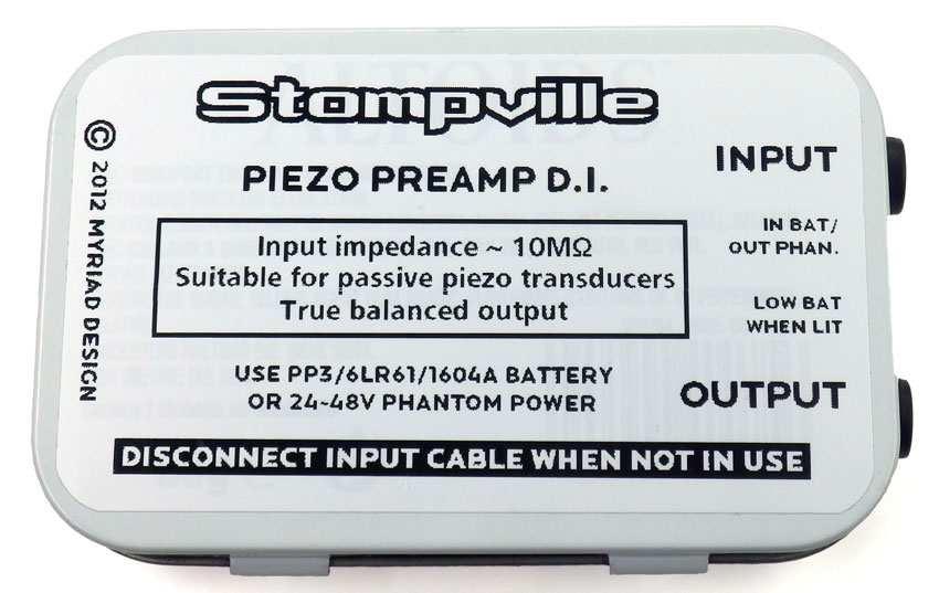
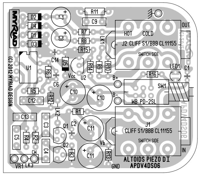
1 Myriad Design Altoids Piezo DI Construction Guide V2 December, The package should include the following items. If any of the items are missing from the package, please contact : Designation Description Marking PCB Altoids 1 Piezo DI - printed circuit APDV4DS06 board R1, R5, R6 1/8W resistor - 10k See Note 2 R2 1/8W resistor - 10M R3 1/8W resistor - 4k7 R4 1/8W resistor - 1M0 R7, R8 1/8W resistor - 33R R9, R10 1/8W resistor - 1k0 R11 1/4W resistor - 10R R12 1/8W resistor - 180k R13 1/8W resistor - 120k R14 1/8W resistor - 220k R15 1/8W resistor - 150k R16 1/8W resistor - 3k6 C1, C6 22p ceramic 22 C2 470p ceramic 470 C3 47n polyester box 47n or.047 C4, C5, C9, C12, 100n polyester box 100n or.1 C13 C7, C8 47u 50V electrolytic C10, C10, C11, 100u 50V electrolytic C11 C14 10n ceramic 10n or 103 D1, D2, D3, D4 1N4148 diode 1N4148 D5 BZX55C33V BZX55C33 Q1, Q2 PF5102 JFET matched pair PF5102 U1 LM833 dual op-amp LM833 U2 TC54VN2902EZB voltage detector 54VN2902 LED1 3mm red LED - Battery Clip J1, J2 1/4 stereo jack socket CL11155 SW1 push-on push-off switch - 8-pin DIL socket - green wire - card with self-adhesive tape/foam - self adhesive foam pad - M3 x 6 pozi pan machine screw - M3 brass nut - label for underside of Altoids tin - template drawing for cutting holes - quick start guide 1 Altoids is a trademark of the Wrigley Company. Their rights are hereby acknowledged. 2 Some resistors may be 4-band and some 5-band. See: 2. It is assumed that you have some experience of soldering and building of simple kits and are confident to build or modify effects pedals. If not, there are many relevant tutorials and videos on Page 1 of 6

, regularly touch your finger to an earthed (grounded) metal object (such as a radiator) and do not handle the sensitive devices any more than you have to.")
2 the internet. Please spend some time familiarising yourself with construction and soldering techniques. 3. Note that Q1, Q2, D1~ D5, U1 and U2 are electrostatic sensitive devices and should be handled with care. If you have an ESD protective wristband, use that. If not, wear clothes made of natural materials (e.g. cotton), regularly touch your finger to an earthed (grounded) metal object (such as a radiator) and do not handle the sensitive devices any more than you have to. In particular, don t remove them from the electrostatic protective package until you are ready to fit them to the board. 4. Solder the items to the PCB according to the silk-screen legend, checking and ensuring that you insert each component in the correct orientation. Page 2 of 6


3 5. Note that if you are not using an Altoids tin as an enclosure and you wish to have a volume control on the output, then omit LK3 and fit a potentiometer (not supplied) to the VR1 connections. The clockwise end of the potentiometer is marked on the PCB CW. 6. Note that LK2 is fitted after the battery clip has been soldered in - and serves to act as a strain relief. 7. Note that the LED must be connected the correct way round. The shorter lead of the LED is the cathode and is shown by the flat side of the PCB legend. If you have cut the leads of the LED and lost track of which was the shorter lead, look inside the LED the cathode is the larger of the two internal structures (note that this is not a universal rule). 8. There is no compelling reason to cut the green earth wire short and you will find it easier to solder the wire to the enclosure if you leave the green wire fairly long. 9. You may wish to test the board before installing it in the enclosure. The input and output sockets are clearly marked on the board. The battery is not connected to the circuit until there is a plug in the input socket. Connect the input to an instrument with a piezo transducer (or indeed any instrument, including electro-acoustic guitar, electric guitar, bass guitar, or even a keyboard, etc). Connect the output to a mixing desk with phantom power. With the switch in the out position, the unit will be phantom powered. With the switch in the in position, the unit will be battery powered. Enclosure 10. Carefully remove the lid of the Altoids tin by bending back the hinge tabs. Cut out the template and stick it on to the tin ensuring that the template is centred. Cut out the holes for the switch, LED and Jack sockets. Take care cutting the larger holes as a normal 10mm HSS Drill bit will likely tear the thin metal. The use of a stepped sheet-metal drill (Google: step drill) or a Q-max chassis punch (Google: q-max 10mm) is recommended. Refit the lid and drill a 3mm hole half way along the lidflange at the front for the screw. Page 3 of 6


4 11. Remove the lid again and screw the nut and screw through the tin. Solder the nut to the case. Note that a 25W soldering iron with a 3mm or larger tip is adequate. 12. Remove the brown cover tape from the underside of the cardboard insulator and carefully fit it to the bottom of the tin. The foam pad should be at the end opposite to the holes. There is no need to remove the backing paper from the top of the foam pad if you stick the battery down to the pad, it will be useless when you change the battery. 13. Carefully solder the end of the green wire to the inside of the tin. Note that the accompanying photo shows a black wire in lieu of the green wire supplied. 14. If you have not already done so, carefully clip all the protruding pins on the rear of the circuit board. In particular, the pins on the sockets should be trimmed back as short as possible. You can use the supplied sticky foam pad to stick the board down (as shown in the photograph below), but longterm experience is that you will be better off gluing the board in place with a little hot-glue, silicone or instant-grab adhesive. 15. Fit the lid and bend the tabs back in place to ensure the lid stays on at the hinge side. Fit the battery, allowing the battery wire to fall across the top of the battery. Close the lid and fit the screw. Lightly shake the unit; the battery should not rattle around. 16. Carefully apply the sticker to the underside of the tin. Page 4 of 6

5 Page 5 of 6
6 17. Note: the reason a stereo jack socket was used on the input side is so that the unit may be switched off when the input cable is removed. 18. Note: the power consumption of the unit is a few milliamps. This means that a fresh alkaline battery will last a few weeks to a few months of moderate use. Try to power the unit from a phantompowered mixing desk if possible. 19. You will need to make/buy a special output lead for this unit. I suggest a length of about 2 metres with a stereo ¼ jack plug one end and a 3-pin male XLR the other end. Connect the tip to pin 2, the ring to pin 3 and the sleeve to pin 1. You should then tell the sound guy that you need a microphone lead with phantom power for your preamp DI. Keep the short custom lead with the unit so you always have it wherever you go to gig. Alternatively, you can make the lead as long as you like (i.e. to go straight to the mixing desk), or make a very short adapter lead, but if you make the lead too short, the weight of the cable with two XLRs dangling off your back pocket (assuming that s where you stash your unit when in use) can be a little annoying. Using the Preamp DI 20. The preamp has very high input impedance. This makes it suitable for passive piezo pickups which may be built-into or added on to stringed or percussion instruments. Generally speaking the cable between the pickup and the instrument should be as short as practical - if you are a violin player you should consider having a lead from your pickup just long enough to comfortably reach the preamp if the preamp is in the back pocket of your jeans or in a pouch slung over the shoulder. The output cable can then be as long as it needs to be to reach the mixing desk or mixer-amp. 21. The preamp may also be used with other types of pickup. For example, you can use it to DI an electro-acoustic guitar or even a keyboard. In fact you can think of it as a general purpose instrument D.I. with the caveat that the DI needs ideally to have a short lead to the instrument. 22. You should disconnect the input cable when the preamp is not in use as this will disconnect the battery and conserve battery life (this is obviously not important for phantom power use). When the battery voltage drops (from 9V) to about 7.3V the LED will illuminate. As the consumption is fairly high (several ma) you should replace the battery (or switch to phantom power) as soon as you notice the light coming on. Note that the low battery light will come on even if you are on phantom power, so you may not need to worry. If you re always going to be on phantom power, you can omit the battery altogether. Copyright Myriad Design. All rights reserved. Disclaimer. The information contained herein is provided in good faith. Myriad Design has no control over the standard of construction of this kit, nor any control over the way the design is implemented or integrated into a system. Therefore, Myriad Design offers no actual or implied warranty of fitness for purpose and Myriad Design will accept no liability for consequential loss or damage. This design is not authorised for use in any safety-critical system. Your statutory rights are not affected. Myriad Design United Kingdom sales@stompville.co.uk Page 6 of 6
7
Myriad Design Altoids Piezo Preamp Construction Guide
 Myriad Design Altoids Piezo Preamp Construction Guide V2 December, 2014 1. The package should include the following items. If any of the items are missing from the package, please contact sales@stompville.co.uk.
Switcher Assembly guide. Switcher Assembly guide 1. Soldering. 2. Switcher3 vs Switcher2. 3. PCB split.
 Safety warning The kits are main powered and use potentially lethal voltages. Under no circumstance should someone undertake the realisation of a kit unless he has full knowledge about safely handling
EHRLUND MICROPHONES EAP MANUAL. for. Ehrlund Acoustic Pickup Ehrlund Preamp Portable Ehrlund Preamp Phantom
 EHRLUND MICROPHONES EAP MANUAL for Ehrlund Acoustic Pickup Ehrlund Preamp Portable Ehrlund Preamp Phantom 1 CONTENTS QUICKSTART... 3 EHRLUND ACOUSTIC PICKUP... 4 PLACING THE PICKUP... 5 KEEPING YOUR PICKUP
Mono Amplifier. LM386 Headphone Amp
 Mono Amplifier LM386 Headphone Amp Layout On/Off Switch - cuts power to the circuit Mono Input Jack: use either L or R or solder together Schematic Step 1 - Parts List 1.) R1-10ohm Resistor - Brown Black
Guitarpedalkits.com Overdrive Pedal Build Instructions
 Page 1 Guitarpedalkits.com Overdrive Pedal Build Instructions Follow the instructions in this guide to build your very own DIY overdrive pedal from GuitarPedalKits.com. If you re a first time builder,
model 101 single channel microphone preamplifier owner s manual Rev C
 2434 30th street, boulder, CO 80306-0204 USA tel 303.443.7454 fax 303.444.4634 info@gracedesign.com / www.gracedesign.com single channel microphone preamplifier Rev C all contents Grace Design/ Lunatec
STEP 0 Prepare the Materials.
 How to Build a Germanium Fuzz Guitar Effect. This document will guide you to build and test your Germanium Fuzz guitar pedal. With all the materials on hand, it takes around 2-4 hours to build it. Try
Build Your Own Clone Chancellor Kit Instructions
 Build Your Own Clone Chancellor Kit Instructions Warranty: BYOC, Inc. guarantees that your kit will be complete and that all parts and components will arrive as described, functioning and free of defect.
MP573 Assembly guide. Soldering. MP573 Assembly guide PCB split PCB split. Document revision 2.2 Last modification : 22/08/17
 MP573 Assembly guide Safety warning The kits are main powered and use potentially lethal voltages. Under no circumstance should someone undertake the realisation of a kit unless he has full knowledge about
BEGINNER'S GUIDE TO AUDIO CONNECTIONS Copyright 2011 by Bruce Bartlett
 BEGINNER'S GUIDE TO AUDIO CONNECTIONS Copyright 2011 by Bruce Bartlett An audio system has so many cables and connectors, it's easy to become confused. What plugs into what? This article will help you
Build Your Own Clone Tremolo Kit Instructions
 Build Your Own Clone Tremolo Kit Instructions Warranty: BYOC, LLC guarantees that your kit will be complete and that all parts and components will arrive as described, functioning and free of defect. Soldering,
Telecaster Wiring Kits Please Read All Instructions Before Beginning. Tools you will need: Soldering tips: Removing Current Wiring: Step 1. Step 2.
 Telecaster Wiring Kits Please Read All Instructions Before Beginning. Tools you will need: Soldering Iron (35 watt preferably) Solder Wet Sponge Wire Clippers Wire Strippers 3/8 Drill Bit 5/32 Drill Bit
Build Your Own Clone British Blues Overdrive Kit Instructions
 Build Your Own Clone British Blues Overdrive Kit Instructions Warranty: BYOC, LLC guarantees that your kit will be complete and that all parts and components will arrive as described, functioning and free
Build Your Own Clone Mouse Kit Instructions
 Build Your Own Clone Mouse Kit Instructions Warranty: BYOC, Inc. guarantees that your kit will be complete and that all parts and components will arrive as described, functioning and free of defect. Soldering,
DI Boxes. Active Stereo DI Box with Extended Dynamic Range and Sum/Split Options
 High headroom design with +48 V phantom power for extended dynamic range Sum and split options for flexible signal routing Fully transformer-isolated design ensures electrical separation between PA and
Build Your Own Clone Reverb Kit Instructions
 Build Your Own Clone Reverb Kit Instructions Warranty: BYOC, LLC guarantees that your kit will be complete and that all parts and components will arrive as described, functioning and free of defect. Soldering,
Build Your Own Clone B.G. Fuzz Kit Instructions
 Build Your Own Clone B.G. Fuzz Kit Instructions Warranty: BYOC, Inc. guarantees that your kit will be complete and that all parts and components will arrive as described, functioning and free of defect.
MICROGRANNY v2.1 - Assembly Guide
 last update: 9. 5. 2017 MICROGRANNY v2.1 - Assembly Guide bastl-instruments.com INTRODUCTION Welcome to the assembly guide for the MicroGranny kit. MicroGranny is a monophonic granular sampler by Bastl
DI Boxes. Active DI Box with Extended Dynamic Range
 High-headroom design with +48 V phantom power for extended dynamic range Fully transformer-isolated design ensures electrical separation between PA and stage equipment Balanced line input on Neutrik* XLR
ABC V1.0 ASSEMBLY IMPORTANT!
 ABC V1.0 ASSEMBLY Before starting this kit, prepare the following tools: Soldering iron (15-20W will do), flush cutters, no.2 hex screwdriver or allen key and phillips screwdriver. Also briefly go through
THE STEP LADDER (K-978)
") THE STEP LADDER (K-978) Footswitch True-bypass = 0 db OUTPUT INPUT Ground shunt switching on the input jack keeps the amp quiet when unplugged from the Step Ladder. Attenuator Pot Full clockwise = 0 db
THE STEP LADDER (K-978) Footswitch True-bypass = 0 db OUTPUT INPUT Ground shunt switching on the input jack keeps the amp quiet when unplugged from the Step Ladder. Attenuator Pot Full clockwise = 0 db
LDB-1 Kit Instructions Page 1 of 8
 LDB-1 Kit Instructions Page 1 of 8 Important Information Congratulations and thank you for your purchase of the LDB-1 Little Drummer Boy Analog Drum Machine Kit! Before you start, please read the enclosed
Build Your Own Clone Classic Overdrive Kit Instructions
 Build Your Own Clone Classic Overdrive Kit Instructions Warranty: BYOC, LLC guarantees that your kit will be complete and that all parts and components will arrive as described, functioning and free of
Build Your Own Clone The Swede Kit Instructions
 Build Your Own Clone The Swede Kit Instructions Warranty: BYOC, Inc. guarantees that your kit will be complete and that all parts and components will arrive as described, functioning and free of defect.
Build Your Own Clone Green Pony Kit Instructions
 Build Your Own Clone Green Pony Kit Instructions Warranty: BYOC, Inc. guarantees that your kit will be complete and that all parts and components will arrive as described, functioning and free of defect.
THE THUNDERDRIVE (K-950)
") THE THUNDERDRIVE (K-950) OUTPUT DISTORTION Unplug when not in use to save battery life. TO AMP IN The Thunderdrive Modkitsdiy.com FROM GUITAR OUT Use these instructions to learn: How to build an effects
THE THUNDERDRIVE (K-950) OUTPUT DISTORTION Unplug when not in use to save battery life. TO AMP IN The Thunderdrive Modkitsdiy.com FROM GUITAR OUT Use these instructions to learn: How to build an effects
Build Your Own Clone Classic Phaser Kit Instructions
 Build Your Own Clone Classic Phaser Kit Instructions Warranty: BYOC, Inc. guarantees that your kit will be complete and that all parts and components will arrive as described, functioning and free of defect.
QRPme Crystal Checker Kit Featured in FDIM 2011 Build-Along
 QRPme Crystal Checker Kit Featured in FDIM 2011 Build-Along This crystal checker circuit was first presented in a workshop given by WA3OPY, AC5UR & W1REX a few years ago at the 4 States QRP Club gathering
Explorer Wiring Kit (assembled)
") Explorer Wiring Kit (assembled) For Vintage, Firestorm & Standard Series Please Read All Instructions Before Beginning. Tools you will need: Soldering Iron (35 watt preferably) Solder Wet Sponge Wire Clippers
Explorer Wiring Kit (assembled) For Vintage, Firestorm & Standard Series Please Read All Instructions Before Beginning. Tools you will need: Soldering Iron (35 watt preferably) Solder Wet Sponge Wire Clippers
Build Your Own Clone Spring Reverb Kit Instructions
 Build Your Own Clone Spring Reverb Kit Instructions Warranty: BYOC, Inc. guarantees that your kit will be complete and that all parts and components will arrive as described, functioning and free of defect.
Build Your Own Clone 27V Boost Kit Instructions
 Build Your Own Clone 27V Boost Kit Instructions Warranty: BYOC, Inc. guarantees that your kit will be complete and that all parts and components will arrive as described, functioning and free of defect.
V6.2 SoftRock Lite Builder s Notes. November 17, 2006
 V6.2 SoftRock Lite Builder s Notes November 17, 2006 Be sure to use a grounded tip soldering iron in building the v6.2 SoftRock circuit board. The soldering iron needs to have a small tip, (0.05-0.1 inch
THE RING RESONATOR (K-975)
") THE RING RESONATOR (K-975) OUTPUT BOOST The Ring Resonator An Octave Up Fuzz Modkitsdiy.com 9 VDC CENTER (-) ADAPTER TO AMP IN FROM GUITAR OUT Unplug when not in use to save battery life. Use these instructions
THE RING RESONATOR (K-975) OUTPUT BOOST The Ring Resonator An Octave Up Fuzz Modkitsdiy.com 9 VDC CENTER (-) ADAPTER TO AMP IN FROM GUITAR OUT Unplug when not in use to save battery life. Use these instructions
Construction Guide European Version
 Construction Guide European Version PCB This section describes how to build up the DRO-350 printed circuit board (PCB). The bare PCB is available for purchase on the order page. Static Protection Bare
Repairing your Porsche 928 Central Warning System (CWS) controller
 controller") Repairing your Porsche 928 Central Warning System (CWS) controller Disclaimer: This procedure is for a 1984 Porsche 928 S controller. Overview: Under the left foot pedal (dead pedal) of the Porsche 928
Repairing your Porsche 928 Central Warning System (CWS) controller Disclaimer: This procedure is for a 1984 Porsche 928 S controller. Overview: Under the left foot pedal (dead pedal) of the Porsche 928
ArduTouch Music Synthesizer
 ArduTouch Music Synthesizer Assembly Instructions rev C Learn To Solder download for free at: http://mightyohm.com/soldercomic The following photos will show you how to solder. But feel free to download
Value Location Qty Potentiometers C1M Distortion 1 A10k Volume 1. Footswitch 3PDT SW1 1. Jacks 1/4 Mono 2 DC Power 1
 Distortion BUILD INSTRUCTIONS Thank you for your purchase of our Distortion+ kit! We have completely redesigned our entire line of kits to be the most user friendly, while still maintaining their same
Build Your Own Clone Crown Jewel Kit Instructions
 Build Your Own Clone Crown Jewel Kit Instructions Warranty: BYOC, Inc. guarantees that your kit will be complete and that all parts and components will arrive as described, functioning and free of defect.
Build Your Own Clone Kuzco Jr. Kit Instructions
 Build Your Own Clone Kuzco Jr. Kit Instructions Warranty: BYOC, Inc. guarantees that your kit will be complete and that all parts and components will arrive as described, functioning and free of defect.
Build Your Own Clone Li l Echo Kit Instructions
 Build Your Own Clone Li l Echo Kit Instructions Warranty: BYOC, Inc. guarantees that your kit will be complete and that all parts and components will arrive as described, functioning and free of defect.
The ability to make basic voltage and resistance measurements using a digital multimeter
 Congratulations on your purchase of a new OneShot chassis! The PC01 OneShot combines a rugged enclosure, power supply, and discrete instrument DI in a compact 1/4U package. A few minutes of assembly are
SoftRock v6.0 Builder s Notes. May 22, 2006
 SoftRock v6.0 Builder s Notes May 22, 2006 Be sure to use a grounded tip soldering iron in building the v6.0 SoftRock circuit board. The soldering iron needs to have a small tip, (0.05-0.1 inch diameter),
FlagShip. Installation Guide / User Manual Effective: January 1 st, Table of contents. 1. FlagShip Preconfiguration
 FlagShip Installation Guide / User Manual Effective: January 1 st, 2016 Please go to our website for the most current version of the FlagShip Installation and Instruction Manual at www.schaller-electronic.com,
Standard Kit #1 (3-way switch)
") Standard Kit #1 (3-way switch) Please Read All Instructions Before Beginning. Tools you will need: Soldering Iron (35 watt preferably) Solder Wet Sponge Wire Clippers 3/8 Drill Bit 1/4 Drill Bit Variable
Standard Kit #1 (3-way switch) Please Read All Instructions Before Beginning. Tools you will need: Soldering Iron (35 watt preferably) Solder Wet Sponge Wire Clippers 3/8 Drill Bit 1/4 Drill Bit Variable
The Engineer s Thumb Compressor/Limiter ValveWizard PCB User Guide (Issue 3 PCBs)
") The Engineer s Thumb Compressor/Limiter ValveWizard PCB User Guide (Issue 3 PCBs) Fig. 1: Circuit schematic Fig. 2: Component layout Fig. 3: Wiring diagram (with millennium bypass) Before populating the
The Engineer s Thumb Compressor/Limiter ValveWizard PCB User Guide (Issue 3 PCBs) Fig. 1: Circuit schematic Fig. 2: Component layout Fig. 3: Wiring diagram (with millennium bypass) Before populating the
Build Your Own Clone Analog Chorus Kit Instructions
 Build Your Own Clone Analog Chorus Kit Instructions Warranty: BYOC, Inc. guarantees that your kit will be complete and that all parts and components will arrive as described, functioning and free of defect.
LA502 Assembly guide Main PCB Resistors - (2)
") LA502 Assembly guide Safety warning The kits are main powered and use potentially lethal voltages. Under no circumstance should someone undertake the realisation of a kit unless he has full knowledge about
LA502 Assembly guide Safety warning The kits are main powered and use potentially lethal voltages. Under no circumstance should someone undertake the realisation of a kit unless he has full knowledge about
2 Interfacing. 2.1 Introduction. The C 411 III pickup is a condenser transducer and therefore needs a power supply. Important!
 2 Interfacing 2.1 Introduction ( Important! 2.2 C 411 III PP 2.2.1 Connecting to Balanced Inputs Refer to fig. 1. The C 411 III pickup is a condenser transducer and therefore needs a power supply. Using
Find a place where you can work through completion, without disturbing your
 Scan by Manual Manor ARIES SYSTEM 300 MUSIC SYNTHESIZER Page I of 4 MODULE AR-334 SEQUENCER ASSEMBLY INSTRUCTIONS It is recommended that you do the following before you proceed: Find a place where you
TRI-STAR PREAMP & TRI-STAR PRO PREAMP
 PRODUCT MANUAL TRI-STAR PREAMP & TRI-STAR PRO PREAMP The Tri-Star Preamp is a 3-channel, internally mounted acoustic guitar preamp. It has been designed specifically for use with the K&K Pure Mini, Pure
Build Your Own Clone Li l Reverb Kit Instructions
 Build Your Own Clone Li l Reverb Kit Instructions Warranty: BYOC, Inc. guarantees that your kit will be complete and that all parts and components will arrive as described, functioning and free of defect.
BUILD YOUR OWN. Fuzz Face SUPER-FREQ.COM
 BUILD YOUR OWN Fuzz Face SUPER-FREQ.COM CHAPTER 1 The Fuzz Face By Mitchell Hudson of super-freq.com, in conjunction with Joe Gore of tonefiend.com. Build your own vintage Fuzz Face! Create a vintage-style
USER GUIDE FISSION BASS
 USER GUIDE FISSION BASS Welcome Thank you for making Fishman a part of your music-making experience. We are proud to offer you the finest tone-shaping products available; high-quality professional-grade
Music Thing Modular SimpleEQ Construction Guide (1206 version)
") Music Thing Modular SimpleEQ Construction Guide (1206 version) Page 1 Useful Links The latest version of this doc and BOM can always be found at http://thonk.co.uk/documents/eq/ A build thread on the Muffwiggler
Music Thing Modular SimpleEQ Construction Guide (1206 version) Page 1 Useful Links The latest version of this doc and BOM can always be found at http://thonk.co.uk/documents/eq/ A build thread on the Muffwiggler
Electric Druid Flangelicious Flanger Project
 Electric Druid Flangelicious Flanger Project (Using either 4KNOBFLANGE or MULTIFLANGE chips) Overview! 2 Build Instructions! 2 Populate the PCB! 2 1N4148 Diodes! 2 Resistors! 2 Cup of tea and soldering
Build instructions for the BLÜE MONSTER Dual band FET OD diy kit!
 Blue Monster, v.1.11... 1(11) Build instructions for the BLÜE MONSTER Dual band FET OD diy kit! Thanx for getting your hands on the BLÜE MONSTER diy kit! In a near future you will have some fun building
Heartboard PCB Assembly Instructions
 Heartboard PCB Assembly Instructions Thanks for purchasing a Heartboard! These instructions will guide you through assembling and testing the Heartboard. Let s get started! Stuff you need Soldering iron
The Walford Electronics Ford Receiver Kit Project Construction Manual
 The Walford Electronics Ford Receiver Kit Project Construction Manual Walford Electronics Ford Receiver construction manual V1.5 Page 1 of 22 Introduction The Ford receiver has four stages: The first stage
Build Your Own Clone Silver Pony 2 Kit Instructions
 Build Your Own Clone Silver Pony 2 Kit Instructions Warranty: BYOC, Inc. guarantees that your kit will be complete and that all parts and components will arrive as described, functioning and free of defect.
The Wave (K-MOD103) GUITAR DWELL REVERB REVERB SWITCH ON OUT OFF
 GUITAR DWELL REVERB REVERB SWITCH ON OUT OFF") The Wave (K-MOD103) OUT IN GUITAR IN DWELL REVERB REVERB SWITCH ON GUITAR OUT POWER ON OFF OFF Please note, there are no labels for this kit. The controls, switches and connectors have only been labeled
The Wave (K-MOD103) OUT IN GUITAR IN DWELL REVERB REVERB SWITCH ON GUITAR OUT POWER ON OFF OFF Please note, there are no labels for this kit. The controls, switches and connectors have only been labeled
Build Your Own Clone Mega Chorus & Vibrato Kit Instructions
 Build Your Own Clone Mega Chorus & Vibrato Kit Instructions Warranty: BYOC, Inc. guarantees that your kit will be complete and that all parts and components will arrive as described, functioning and free
SoftRock v6.0 Builder s Notes. April 6, 2006
 SoftRock v6.0 Builder s Notes April 6, 006 Be sure to use a grounded tip soldering iron in building the v6.0 SoftRock circuit board. The soldering iron needs to have a small tip, (0.05-0. inch diameter),
Build Your Own Clone Silver Pony Kit Instructions
 Build Your Own Clone Silver Pony Kit Instructions Warranty: BYOC, Inc. guarantees that your kit will be complete and that all parts and components will arrive as described, functioning and free of defect.
Pacific Antenna Field Strength Indicator Kit
 Pacific Antenna Field Strength Indicator Kit Description The Field Strength Indicator kit from Pacific Antenna provides a visual way to monitor the presence and relative strength RF fields through the
Designed to send specific MIDI information upon each press. Ultra-low current requirement means a single coin cell will last years
 PedalSync MIDI Data Module Key Features Discrete MIDI Data delivery in a compact design Designed to send specific MIDI information upon each press Ultra-low current requirement means a single coin cell
Line-Following Robot
 1 Line-Following Robot Printed Circuit Board Assembly Jeffrey La Favre October 5, 2014 After you have learned to solder, you are ready to start the assembly of your robot. The assembly will be divided
Ai1 OWNER S MANUAL. Getting Started:
 Ai1 OWNER S MANUAL Thank you for your purchase. We have developed a quality DI with preamp for use by professional musicians with added features for home or private practice. Features: The Ai1 is a quality
Warning DECLARATION OF CONFORMITY. For your protection, please read the following:
 DECLARATION OF CONFORMITY Manufacturer s Name: DigiTech Manufacturer s Address: 8760 S. Sandy Parkway Sandy, Utah 84070, USA declares that the product: Product name: Bass Multi Chorus Product option: all
Value Location Qty Transistors 2N5485 Q1, Q2, 4 Q3, Q4 2N5087 Q5 1. Trim Pots 250k VTRIM 1. Potentiometers C500k Speed 1. Toggle Switch On/On Vibe 1
 P-90 BUILD INSTRUCTIONS Thank you for your purchase of our P-90 kit! We have completely redesigned our entire line of kits to be the most user friendly, while still maintaining their same great sound!
Balanced Modulator. Model 9748 Assembly and Using Manual PAiA Corporation
 Balanced Modulator Model 9748 Assembly and Using Manual This second-generation 9700-series processing element for modular sound synthesizers is designed to provide great sound and excellent value. Audio
Instructions for Lighting an S Scale Caboose
 Instructions for Lighting an S Scale Caboose The S Scale Caboose lighting kit is adaptable for most caboose models of rolling stock including American Flyer (TM) and contains the same components as found
NEW WAVE CV GENERATOR Build Document last updated september 2017 for PCB version 1.0
 NEW WAVE CV GENERATOR Build Document last updated september 2017 for PCB version 1.0 The New Wave is a Control Voltage Generator. It has two LFO's (low frequency oscillators) and four different output
T L Audio. User Manual EQ1 VALVE EQUALISER. Tony Larking Professional Sales Limited, Letchworth, England.
 T L Audio User Manual EQ1 VALVE EQUALISER Tony Larking Professional Sales Limited, Letchworth, England. Tel: 01462 490600, International +44 1462 490600. Fax: 01462 490700, International +44 1462 490700.
Build your own boombox
 Build your own boombox This amplifier kit with plug-in board and all necessary components is easy and quick to assemble, requires no soldering and is great fun. Listen to your favourite music with your
D-TAR Installation Instructions. Wave-Length. Volume & Tone Module.
 D-TAR Installation Instructions www.dtar.com Wave-Length Volume & Tone Module www.dtar.com Contents Read This First...3 Tools required...4 Installing the Volume & Tone Module...5 Limited Warranty...8 Information
SoftRock v5.0 Builder s Notes. December 12, Building a QSD Kit
 SoftRock v5.0 Builder s Notes December 12, 2005 Building a QSD Kit Be sure to use a grounded tip soldering iron in building the QSD board. The soldering iron needs to have a small tip, (0.05-0.1 inch diameter),
Build Your Own Clone Li l Analog Chorus Kit Instructions
 Build Your Own Clone Li l Analog Chorus Kit Instructions Warranty: BYOC, Inc. guarantees that your kit will be complete and that all parts and components will arrive as described, functioning and free
Assembly Instructions for the 1.5 Watt Amplifier Kit
 Assembly Instructions for the 1.5 Watt Amplifier Kit 1.) All of the small parts are attached to a sheet of paper indicating both their value and id. 2.) Leave the parts affixed to the paper until you are
RF Current Meter Kit
 Kit When assembled, this kit provides you with a simple but effective means of measuring the current in antenna wires, and of looking for braid currents on coax feeders. The more current you can get flowing
Warning For your protection, please read the following:
 DECLARATION OF CONFORMITY Manufacturer s Name: Manufacturer s Address: declares that the product: Product name: Product option: DigiTech 8760 S. Sandy Parkway Sandy, Utah 84070, USA HardWire CM-2 All (requires
THE TRILL TREMOLO (K-960)
") THE TRILL TREMOLO (K-60) DEPTH SPEED The Trill Tremolo Modkitsdiy.com Unplug when not in use to save battery life. TO AMP IN FROM GUITAR OUT Use these instructions to learn: How to build an effects pedal
THE TRILL TREMOLO (K-60) DEPTH SPEED The Trill Tremolo Modkitsdiy.com Unplug when not in use to save battery life. TO AMP IN FROM GUITAR OUT Use these instructions to learn: How to build an effects pedal
Build Your Own Clone Parametric Multi-Band Compressor Kit Instructions
 Build Your Own Clone Parametric Multi-Band Compressor Kit Instructions Warranty: BYOC, Inc. guarantees that your kit will be complete and that all parts and components will arrive as described, functioning
THE AGGRESSOR (K-995)
") THE AGGRESSOR (K-99) TONE VOLUME DISTORTION MID-SHIFT SWITCH LED The Aggressor Distortion Pedal Modkitsdiy.com 9 VDC CENTER (-) ADAPTER TO AMP IN FROM GUITAR OUT Unplug when not in use to save battery
THE AGGRESSOR (K-99) TONE VOLUME DISTORTION MID-SHIFT SWITCH LED The Aggressor Distortion Pedal Modkitsdiy.com 9 VDC CENTER (-) ADAPTER TO AMP IN FROM GUITAR OUT Unplug when not in use to save battery
Axis Fuzz Kit Building Manual
 Axis Fuzz Kit Building Manual Effect Pedal Kits: Axis Fuzz The Axis Fuzz Kit is based in the Roger Mayer Axis Fuzz, the effect pedal responsible for Jimi Hendrix sound in Axis Bold As Love. What else is
Outboard Acoustic Preamps
 User Guide Outboard Acoustic Preamps Includes Instructions for Model GII General Purpose Preamp Model BII Acoustic Bass Preamp Pro EQ II Acoustic Instrument Preamp / EQ Outboard Acoustic Preamps Thank
Minty Amp assembly instructions
 Minty Amp assembly instructions Parts Required: LM386 OpAmp (included in kit) 2x 100uf (min 16v) Electrolytic Capacitors (included in kit) 0.1uf Ceramic Capacitor (included in kit) 0.047uf Ceramic Capacitor
Chunky Cheese Build Guide Rev
 Chunky Cheese Build Guide Rev. 2008-08-04 The Chunky Cheese is a slightly-modified version of the discontinued Big Cheese fuzz pedal. Table of Contents Table of Contents... 1 PCB Layout... 2 Parts List...
MONO AMPLIFIER KIT ESSENTIAL INFORMATION. Version 3.0 CREATE YOUR OWN SPEAKER DOCK WITH THIS
 ESSENTIAL INFORMATION BUILD INSTRUCTIONS CHECKING YOUR PCB & FAULT-FINDING MECHANICAL DETAILS HOW THE KIT WORKS CREATE YOUR OWN SPEAKER DOCK WITH THIS MONO AMPLIFIER KIT Version 3.0 Build Instructions
T L Audio INDIGO SERIES. User Manual VP-2051 VALVE VOICE PROCESSOR. Tony Larking Professional Sales Limited, Letchworth, England.
 T L Audio INDIGO SERIES User Manual VP-2051 VALVE VOICE PROCESSOR Tony Larking Professional Sales Limited, Letchworth, England. Tel: 01462 490600. International +44 1462 490600. Fax: 01462 490700. International
Specimen Products Single Ended Stereo Amp Instruction Book
 Specimen Products Single Ended Stereo Amp Instruction Book Specimen tube amplifier designs are informed by decades of servicing and building musical instrument amps. As a result of being subjected to the
Pacific Antenna Wall Wart Tamer 2.0 Kit
 Pacific Antenna Wall Wart Tamer 2.0 Kit Description The Wall Wart Tamer lets you utilize those surplus computer and wall pack power supplies as a clean, adjustable voltage, DC power source for radios and
Build Your Own Clone Li l Comp Kit Instructions
 Build Your Own Clone Li l Comp Kit Instructions Warranty: BYOC, Inc. guarantees that your kit will be complete and that all parts and components will arrive as described, functioning and free of defect.
Elektor Construction Guide TAPIR
 Elektor Construction Guide TAPIR The TAPIR is a three-dimensional assembly. To ensure good access to all soldering points, we recommend assembling the kit exactly according to the described sequence. 1
Digital Electronics & Chip Design
 Digital Electronics & Chip Design Lab Manual I: The Utility Board 1999 David Harris The objective of this lab is to assemble your utility board. This board, containing LED displays, switches, and a clock,
Installation tutorial for Console Customs Xbox Mode Dual Button (RFX-5B) Rapid fire Microchip for all Wired and Wireless controllers
 Rapid fire Microchip for all Wired and Wireless controllers") Installation tutorial for Console Customs Xbox 360 5-Mode Dual Button (RFX-5B) Rapid fire Microchip for all Wired and Wireless controllers This tutorial is designed to aid you in installation of a console
Installation tutorial for Console Customs Xbox 360 5-Mode Dual Button (RFX-5B) Rapid fire Microchip for all Wired and Wireless controllers This tutorial is designed to aid you in installation of a console
Build Your Own Clone Analog Vibrato Kit Instructions
 Build Your Own Clone Analog Vibrato Kit Instructions Warranty: BYOC, Inc. guarantees that your kit will be complete and that all parts and components will arrive as described, functioning and free of defect.
Standard Kit #1 (5-way switch)
") Standard Kit #1 (5-way switch) Please Read All Instructions Before Beginning. Tools you will need: Soldering Iron (35 watt preferably) Solder Wet Sponge Wire Clippers 3/8 Drill Bit 1/4 Drill Bit Variable
Standard Kit #1 (5-way switch) Please Read All Instructions Before Beginning. Tools you will need: Soldering Iron (35 watt preferably) Solder Wet Sponge Wire Clippers 3/8 Drill Bit 1/4 Drill Bit Variable
Read Me First! PICKUP INSTALLATION MATRIX INFINITY VT MATRIX INFINITY MIC BLEND INSTALLATION GUIDE. *Minimum 20⁰ string break angle
 MATRIX INFINITY VT MATRIX INFINITY MIC BLEND INSTALLATION GUIDE Read Me First! We recommend having this system installed by an experienced repair technician *Minimum 20⁰ string break angle PICKUP INSTALLATION
L. R. B A G G S P I C K U P S
 L. R. B A G G S P I C K U P S ibeam (PASSIVE) INSTALLATION MANUAL & USER'S GUIDE TABLE OF CONTENTS 483 N. FRONTAGE RD. NIPOMO, CA 93444 WWW.LRBAGGS.COM 1. Package contents 2. Overview and cautions 3. Strapjack
Contents in Detail. Part I: Quick Projects and Tinkering...1. Acknowledgments...xix. Introduction...xxi. Project 1: The Slinkiphone...
 Contents in Detail Acknowledgments...xix Introduction...xxi What s in This Book?...xxii A Note on Safety...xxiii Further Reading...xxiii Support and Contact...xxv License...xxv Part I: Quick Projects and