Building the Toothpick Audio CW Filter
|
|
|
- Godwin Ball
- 6 years ago
- Views:
Transcription
1 Building the Toothpick Audio CW Filter Introduction The toothpick is a simple variable bandpass audio filter designed to compliment the Splinter QRPp Trans-Receiver. The filter also contains an audio amplifier which can produce room-filling volume when used with an external speaker. When used with the Splinter the filter has the added bonus of amplifying the sidetone oscillator during transmit. Although the design is simple and physically similar to the Splinter there is no reason that the Toothpick could not be used with other simple or vintage receivers needing a little extra audio filtering. Building Rules 1. Take your time. We recommend that you take at least two or three days to complete your kit. It will take three coats of paint on your breadboard anyway to give it a good finish and a day of drying between each coat is recommended. So, if you take your time, in three days you can have a beautiful working project that you will be proud to own and operate. 2. If you don t know how to solder parts on a circuit board, get help. Learning to solder is not hard, but please do not start this kit if you have never soldered before! 3. Most of the parts are tiny. Please use a magnifying glass. 4. Build the kit by the instructions, one step at a time. 5. Use protective eyewear. 6. Be careful with the ICs and transistors to avoid damage from static. 7. All parts should be mounted flush or as close as possible to the circuit board keeping leads short. After soldering, clip all wires close to the board. Finishing The Breadboard The wooden breadboard furnished with your kit is your opportunity to express yourself. You get to finish it any way that you like...pick your color, pick your finish. MAY WE SUGGEST THE FOLLOWING? 1. Use fine grit sand paper to remove any roughness from the wood. 2. You can use brush on or spray paint or stain or no finish at all...it s up to you.
2 3. You are in charge of getting the board ready. Three coats with light sanding between coats and about 24 hours of drying time will produce great results. NOTE: The decals that will be placed on your breadboard at the end of kit construction are black and red. SO, it is best to use a lighter color (e.g. white, grey, yellow, light green or blue). 4. When the board is finished, locate the circuit board and place it on top of the breadboard. Center the circuit board and using a small nail, phillips screwdriver or other small pointed object, push a small starter hole into the breadboard at each corner mounting hole. The starter hole will help you to mount the assembled circuit board in the proper location at the end of the project. Place the breadboard aside for now. Building the Circuit Board Tools and supplies needed to build the circuit board: 1. needle nose pliers 2. diagonal cutters 3. small flat blade and phillips screwdrivers 4. Magnifying glass watt soldering iron Locate the parts bag. All of the parts required for circuit board construction are enclosed. You can work from the bag and find each part as it is called for, but placing all of the parts from the bag into a bowl or small plastic tray may make it easier to sort and properly identify the parts. As each part is called for, be sure to identify it, then locate the proper mounting holes on the board. Insert the part and check it s placement before soldering it in place. Cut all leads flush with the board. 1. Locate J1 a 1/8th inch phone jack and it s mounting position on the left rear edge of the circuit board. Refer to the diagram and modify the two lower soldering lugs to fit in the two mounting holes closest to the left side of the board. Bend the lower back lug (lug B) 90 degrees so that it points down like the front lug. Using diagonal cutters, clip off the ends of lugs A and B as close as possible to the soldering hole. The remaining lugs should be as long as possible so that they will fit through the mounting holes in the circuit board. Place J1 into position with lug A and B in the mounting holes and solder with J1 flush against the board. The
3 lugs may need slight trimming with the diagonal cutters to fit the holes. Lug B may not come all the way through the hole, but a little extra solder to fill the hole will sufficiently hold it in place. Use a one inch bare wire to complete mounting J1. Pass one end of the wire through lug C of J1 and into the circuit board mounting hole. Secure the top end of the wire to lug C of J1 and solder in place. Solder the other end of the wire on the bottom of the board and clip the excess wire. 2. Locate screw terminal J2 and the mounting position on the top side of the board near J1. Place J2 in the two mounting holes with the wire insertion holes facing off the back of the board. You can slightly bend the leads on the bottom of the board to help keep J2 flush to the top of the board. Solder the two leads. 3. Locate screw terminal J3 and the mounting position on the top side of the board near J2. Place J3 in the two mounting holes with the wire insertion holes facing off the back of the board. You can slightly bend the leads on the bottom of the board to help keep J3 flush to the top of the board. Solder the two leads. 4. Locate screw terminal J4 and the mounting position on the top side of the board near J3. Place J4 in the two mounting holes with the wire insertion holes facing off the back of the board. You can slightly bend the leads on the bottom of the board to help keep J4 flush to the top of the board. Solder the two leads. 5. Locate SW1 a single pole double throw slide switch. Mount it on the left rear of the board and solder it in place. The mounting pins will be tight and may require some gentle force to push it flush with the board. 6. Locate SW2 a double pole double throw slide switch. Mount it on the right rear of the board and solder it in place. The mounting pins will be tight and may require some gentle force to push it flush with the board. 7. Locate IC1 a LM386 integrated circuit. Mount it on the left side of the board and solder it in place. You will need to slightly bend the legs on each side of the IC to facilitate fitting into the parallel rows of mounting holes. Observe the screen printed mounting key on the circuit board. 8. Locate IC2 a LM741 integrated circuit. Mount it on the right side of the board and solder it in place. You will need to slightly bend the legs on each side of the IC to facilitate fitting into the parallel rows of mounting holes. Observe the screen printed mounting key on the circuit board. 9. Locate C1 a 220uf. electrolytic capacitor. Observe the proper polarity and solder it in place. 10. Locate C2 a 47uf. electrolytic capacitor. Observe the proper polarity and solder it in place.
4 11. Locate C3 a 0.01uf (103) ceramic capacitor. Mount and solder in place. 12. Locate C4 a 0.01uf. (103) ceramic capacitor. Mount and solder in place. 13. Locate C5 a 0.047uf. (473) ceramic capacitor. Mount and solder in place. 14. Locate C6 a 0.01 (103) ceramic capacitor. Mount and solder in place. 15. Locate C7 a 10uf. electrolytic capacitor. Observe polarity as you mount and solder in place. 16. Locate C8 a 0.1uf (104) ceramic capacitor. Mount and solder in place. 17. Locate C9 a 0.1uf (104) ceramic capacitor. Mount and solder in place. 18. Locate R1 a 47K ohm resistor (yellow, purple, orange) mount and solder in place. 19. Locate R2 a 270K ohm resistor (red, purple, yellow) mount and solder in place. 20. Locate R3 a 270 ohm resistor (red, purple, brown) mount and solder in place. 21. Locate R4 a 100 ohm resistor (brown, black, brown) mount and solder in place. 22. Locate R5 a 1K ohm resistor (brown, black, red) mount and solder in place. 23. Locate R6 a 10K ohm resistor (brown, black, orange) and solder in place. 24. Locate R7 a 10K ohm potentiometer. Mount and solder in place. 25. Locate R8 a 1K ohm potentiometer. Mount and solder in place. This completes construction of the circuit board. Inspect the board for proper parts placement. Make sure that solder connections are good and that there are no solder bridges. Final Assembly 1. Mount the circuit board on your finished wooden breadboard with four brass wood screws and four 3/16th inch black spacers. 2. Install the knobs on potentiometers R7 and R8.
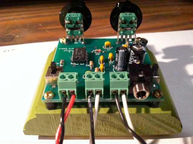
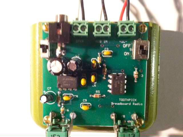
5 3. Mount the four rubber feet on the bottom of the wooded breadboard in the corners. 4. Mount the decals on your finished breadboard. Cut the decals out with scissors and place in warm water for about seconds. Place the wet decals on the breadboard in the correct place and slide the backing away. Carefully align the decals and allow them to dry. Using the Filter There are four possible interconnections to the filter which are made at J1 through J4. J1 is a 1/8 inch phone jack. This jack is for audio output to stereo earphones. Audio is present when SW1 is switched towards the front of the board. J2 is a 2 position screw terminal. This terminal is used to connect an external speaker. Audio is present when SW1 is switched towards the rear of the board. Looking at the back of the filter, the screw terminal on the left is ground. NOTE: R6 (10K) limits audio level for earphones / small speakers. If more volume is needed to drive larger speakers, replace R6 with a 1K resistor or a jumper wire. J3 is a 2 position screw terminal. This terminal is the audio input to the filter from your receiver. Looking at the back of the filter, the screw terminal on the left is ground. J4 is a 2 position screw terminal. This terminal is the DC voltage input. Looking at the back of the filter, the screw terminal on the left is (negative) ground. Positive voltage goes to the terminal on the right. The filter requires 9 to 12 volts DC. CAUTION: Be sure that the positive voltage is connected to the terminal on the right as you are looking at the rear of the filter. Reverse polarity will damage the filter! When SW2 (located on the right side rear of the board) is in the forward position, the filter is on and operational (ON). When SW2 is switched to the rear the filter is off, but the audio is bypassed to SW1. R7 controls the audio output (volume) of the filter when SW2 is in the on position. R8 controls the bandpass frequency when SW2 is in the on position. The band pass will peak from approximately 1000 Hertz to 700 Hertz. While this type of filter will not provide the selectivity of an I.F. crystal type, it does provide improved audio selectivity by attenuating high and low frequency audio signals above and below the bandpass, especially the high frequencies.
6 After making appropriate connections turn on the filter and adjust the filter and receiver volume to the desired level. You will notice that as you tune through a signal, a peak in volume will occur. This peak frequency can be adjusted with R8. When R8 is all the way to the right, the bandpass peak is at approximately 700 Hertz. With R8 all the way to the left, the bandpass peak is at approximately 1000 Hertz. NOTE: Most operators prefer Hz for copying cw. Most cheap earbuds/earphones have very high audio responses (above 1000 Hz) so when using these devices set R8 all the way to the left and tune in the desired signal for peak signal. Better low frequency response is found when using good headphones or speakers. In any case, by using the volume, bandpass and receiver controls you will be able to improve signal reception. Connecting the Toothpick to the Splinter You may use the included hook-up wire or your own wire to connect between the appropriate terminals provided on the Toothpick and Splinter (audio and power). The audio connection will require a 1/8th inch stereo phone plug. Connect the ground to the ring and the audio line to the tip and or the center ring. Use wire connected to an external speaker to connect to the speaker (SPKR) terminal. Use caution when connecting the power from the Splinter to the Toothpick. The wires will need to be piggy backed to the power wires already in the Splinter power screw terminals. Alternately, you may run power directly to the Toothpick from your power source or a 9.0 volt battery. Just make sure to put the positive and negative wires in the correct side of the power terminal. SEE PHOTOS
7
Building the Sawdust Regenerative Receiver
 Building the Sawdust Regenerative Receiver Introduction The Sawdust is a super regenerative receiver using the basic Armstrong design architecture. The receiver uses one toroidal transformer to provide
Building the Sawdust Regenerative Receiver
 Building the Sawdust Regenerative Receiver Introduction The Sawdust is a super regenerative receiver using the basic Armstrong design architecture. The receiver uses one toroidal transformer to provide
Read This Page First
 Read This Page First If you are reading this you know the manuals are always available at QRPKITS.com. This is version 8.0 of the manual dated 4/27/2016. There is no need to print out the whole assembly
Cricket 80a Assembly Manual v Copyright David Cripe NM0S The 4 State QRP Group
 Cricket 80a Assembly Manual v. 1.0 Copyright 2017 David Cripe NM0S The 4 State QRP Group Introduction Thank you for purchasing a CRICKET 80a Transceiver. We hope you will enjoy building it and find it
SoftRock v5.0 Builder s Notes. December 12, Building a QSD Kit
 SoftRock v5.0 Builder s Notes December 12, 2005 Building a QSD Kit Be sure to use a grounded tip soldering iron in building the QSD board. The soldering iron needs to have a small tip, (0.05-0.1 inch diameter),
Guitarpedalkits.com Overdrive Pedal Build Instructions
 Page 1 Guitarpedalkits.com Overdrive Pedal Build Instructions Follow the instructions in this guide to build your very own DIY overdrive pedal from GuitarPedalKits.com. If you re a first time builder,
Pacific Antenna Easy TR Switch
 Pacific Antenna Easy TR Switch Kit Description The Easy TR Switch is an RF sensing circuit with a double pole double throw relay that can be used to automatically switch an antenna between a separate receiver
Pacific Antenna - Easy TR Switch
 Pacific Antenna - Easy TR Switch Kit Description The Easy TR Switch is an RF sensing switch that can be used to switch an antenna between a receiver and transmitter. It also has a second switched pair
SoftRock v6.0 Builder s Notes. May 22, 2006
 SoftRock v6.0 Builder s Notes May 22, 2006 Be sure to use a grounded tip soldering iron in building the v6.0 SoftRock circuit board. The soldering iron needs to have a small tip, (0.05-0.1 inch diameter),
Easy Transmitter. Support ETX_REV5_Manual V2.7 Revised
 Easy Transmitter Introduction The Easy Transmitter kit from qrpkits.com provides a basic, crystal controlled transmitter with VXO tuning to provide a small tuning range around the crystal frequency. It
Assembly Instructions
 Assembly Instructions For the SSQ-2F 3.1 MHz Rife Controller Board Kit v1.41 Manual v1.00 2012 by Ralph Hartwell Spectrotek Services GENERAL ASSEMBLY INSTRUCTIONS Arrange for a clean work surface with
Assembly Instructions for the 1.5 Watt Amplifier Kit
 Assembly Instructions for the 1.5 Watt Amplifier Kit 1.) All of the small parts are attached to a sheet of paper indicating both their value and id. 2.) Leave the parts affixed to the paper until you are
MICROGRANNY v2.1 - Assembly Guide
 last update: 9. 5. 2017 MICROGRANNY v2.1 - Assembly Guide bastl-instruments.com INTRODUCTION Welcome to the assembly guide for the MicroGranny kit. MicroGranny is a monophonic granular sampler by Bastl
Pacific Antenna Easy Transmitter Kit
 Pacific Antenna Easy Transmitter Kit Introduction The Easy Transmitter kit from qrpkits.com provides a crystal controlled transmitter with VXO tuning. The circuit consists of a N3904 based crystal oscillator
V6.2 SoftRock Lite Builder s Notes. November 17, 2006
 V6.2 SoftRock Lite Builder s Notes November 17, 2006 Be sure to use a grounded tip soldering iron in building the v6.2 SoftRock circuit board. The soldering iron needs to have a small tip, (0.05-0.1 inch
CW-ADD. Universal CW Adapter for SSB Transceivers. Assembly manual. Last updated: October 1,
 CW-ADD Universal CW Adapter for SSB Transceivers Assembly manual Last updated: October 1, 2017 ea3gcy@gmail.com Updates and news at: www.ea3gcy.com Thanks for building the Universal CW Adapter kit CW-ADD
Ten Tec DDS Board Assembly Procedure
 05 May 2014 Ten Tec DDS Board Assembly Procedure You will find a photo of a completed board at the end of these instructions. Refer it whenever clarification is required. 1. AD9835 Attachment If you purchased
SoftRock v6.0 Builder s Notes. April 6, 2006
 SoftRock v6.0 Builder s Notes April 6, 006 Be sure to use a grounded tip soldering iron in building the v6.0 SoftRock circuit board. The soldering iron needs to have a small tip, (0.05-0. inch diameter),
Specimen Products Single Ended Stereo Amp Instruction Book
 Specimen Products Single Ended Stereo Amp Instruction Book Specimen tube amplifier designs are informed by decades of servicing and building musical instrument amps. As a result of being subjected to the
LITTLE NERD v1.1 Assembly Guide
 last update: 9. 3. 2016 LITTLE NERD v1.1 Assembly Guide bastl instruments.com INTRODUCTION This guide is for building Little Nerd module from Bastl Instruments. It is good to have basic soldering skills
Mono Amplifier. LM386 Headphone Amp
 Mono Amplifier LM386 Headphone Amp Layout On/Off Switch - cuts power to the circuit Mono Input Jack: use either L or R or solder together Schematic Step 1 - Parts List 1.) R1-10ohm Resistor - Brown Black
KASTLE v1.5 - Assembly Guide
 last update: 14. 12. 2017 KASTLE v1.5 - Assembly Guide bastl-instruments.com INTRODUCTION Welcome to the assembly guide for the Kastle kit - mini modular synthesizer. It is suitable for beginners. It is
Pacific Antenna Field Strength Indicator Kit
 Pacific Antenna Field Strength Indicator Kit Description The Field Strength Indicator kit from Pacific Antenna provides a visual way to monitor the presence and relative strength RF fields through the
Assembly and User Guide
 Assembly and User Guide AtariPunkr is an adjustable stepped tone generator. AtariPunkr provides hours of fun everyone! Powered by: 9V Battery Outputs: Mylar Speaker (Included) Stereo Output (3.5mm Jack)
S-Pixie QRP Kit. Student Manual. Revision V 1-0
 S-Pixie QRP Kit Student Manual Revision V 1-0 Introduction The Pixie 2 is a small, versatile radio transceiver that is very popular with QRP (low power) amateur radio operators the world over. It reflects
Building a Bitx20 Version 3
 Building a Bitx20 Version 3 The board can be broken into sections and then built and tested one section at a time. This will make troubleshooting easier as any problems will be confined to one small section.
Pacific Antenna Code Practice Oscillator Kit
 Pacific Antenna Code Practice Oscillator Kit This kit is offered to initiate the first time builder in the various techniques of mechanical and electronic kit construction. At the end of the approximately
Polyphase network kit
 Polyphase network kit 1. Introduction This polyphase network module is designed to be used with the QRP Labs receiver module kit. It takes as inputs, four phase audio from the Quadrature Sampling Detector
Bill of Materials: General Purpose Alarm, Pulsed PART NO
 General Purpose Alarm, Pulsed PART NO. 2190207 I hate alarms that sound continuously - unless they are smoke alarms. Smoke alarms should be annoying, but others should not. I wanted an alarm for a function
FM Wireless Microphone Kit Instructions for Assembly Page 1 of 5
 Instructions for Assembly Page 1 of 5 1. Find Resistor R1. Remove any tape that may be attached to the leads. Bend the leads as needed to insert Resistor R1 into the printed circuit board in the holes
WA3RNC 30 METER CRYSTALPLEXER TRANSMITTER KIT ASSEMBLY INSTRUCTIONS
 WA3RNC 30 METER CRYSTALPLEXER TRANSMITTER KIT ASSEMBLY INSTRUCTIONS Description The WA3RNC 30 Meter Crystalplexer is a low power crystal controlled QRP transmitter offering a significantly improved tuning
THE RING RESONATOR (K-975)
") THE RING RESONATOR (K-975) OUTPUT BOOST The Ring Resonator An Octave Up Fuzz Modkitsdiy.com 9 VDC CENTER (-) ADAPTER TO AMP IN FROM GUITAR OUT Unplug when not in use to save battery life. Use these instructions
THE RING RESONATOR (K-975) OUTPUT BOOST The Ring Resonator An Octave Up Fuzz Modkitsdiy.com 9 VDC CENTER (-) ADAPTER TO AMP IN FROM GUITAR OUT Unplug when not in use to save battery life. Use these instructions
Wiring Manual NEScaf April 2010 (August 2006)
") Wiring Manual NEScaf April 2010 (August 2006) Switched Capacitor Audio Filter The NEScaf is a switched capacitor audio filter (acronym SCAF) built around a building-block type filter chip. The NEScaf will
Wiring Manual NEScaf April 2010 (August 2006) Switched Capacitor Audio Filter The NEScaf is a switched capacitor audio filter (acronym SCAF) built around a building-block type filter chip. The NEScaf will
LED Field Strength Indicator Kit
 LED Field Strength Indicator Kit Description The Field Strength Indicator kit from Qrpkits.com provides a visual way to monitor RF fields through the brightness of an LED. It will respond to RF fields
Digital Electronics & Chip Design
 Digital Electronics & Chip Design Lab Manual I: The Utility Board 1999 David Harris The objective of this lab is to assemble your utility board. This board, containing LED displays, switches, and a clock,
THE TRILL TREMOLO (K-960)
") THE TRILL TREMOLO (K-60) DEPTH SPEED The Trill Tremolo Modkitsdiy.com Unplug when not in use to save battery life. TO AMP IN FROM GUITAR OUT Use these instructions to learn: How to build an effects pedal
THE TRILL TREMOLO (K-60) DEPTH SPEED The Trill Tremolo Modkitsdiy.com Unplug when not in use to save battery life. TO AMP IN FROM GUITAR OUT Use these instructions to learn: How to build an effects pedal
Pacific Antenna Low Pass Filter Kit
 Pacific Antenna Low Pass Filter Kit Description Many basic transmitter and/or transceiver designs have minimal filtering on their output and frequently have significant harmonic content in their signals.
LDB-1 Kit Instructions Page 1 of 8
 LDB-1 Kit Instructions Page 1 of 8 Important Information Congratulations and thank you for your purchase of the LDB-1 Little Drummer Boy Analog Drum Machine Kit! Before you start, please read the enclosed
Bill of Materials: Metronome Kit PART NO
 Metronome Kit PART NO. 2168325 The metronome kit allows you to build your own working electronic metronome. Features include a small speaker, flashing LED, and the ability to switch between several different
Pacific Antenna Easy SWR Indicator Kit
 Pacific Antenna Easy SWR Indicator Kit Description Monitoring the match of an antenna to your transmitter or adjusting an antenna tuner for best match requires an indicator of the reflected power as an
Code Practice Oscillator (CPO) For kit building instructions turn to Page 3.
 For kit building instructions turn to Page 3.") Code Practice Oscillator (CPO) For kit building instructions turn to Page 3. Overview Many thanks for your purchase of this code practice oscillator or CPO, this guide is intended to allow you to quickly
Code Practice Oscillator (CPO) For kit building instructions turn to Page 3. Overview Many thanks for your purchase of this code practice oscillator or CPO, this guide is intended to allow you to quickly
ELECRAFT Application Note
 ELECRAFT Application Note Front Panel Microphone Circuit Modification Revision A, November 12, 2008 Copyright 2008, Elecraft, Inc., All Rights Reserved Background Some K3 owners have noted distorted transmit
12V Dimmer Kit, version 2
 12V Dimmer Kit, version 2 User Manual Description The 12V Dimmer Kit V2 is an especially efficient PWM (pulse-width modulation) controller for 12V loads up to 60 watts. It features a single dial control
SpikerBox v1.3 DIY Instructions
 SpikerBox v. DIY Instructions Prepare yourself. In hours, you will have built your own SpikerBox to begin doing neuroscience and whatever your creative mind can conjure. Materials Needed:. A Backyard Brains
Bill of Materials: Electronic Organ PART NO
 Electronic Organ PART NO. 2177918 This project is based on IC555 timer circuit that is capable of providing the set of musical notes: DO, RE, MI,... And with the help of some components and essential devices,
The Walford Electronics Ford Receiver Kit Project Construction Manual
 The Walford Electronics Ford Receiver Kit Project Construction Manual Walford Electronics Ford Receiver construction manual V1.5 Page 1 of 22 Introduction The Ford receiver has four stages: The first stage
Value Location Qty Potentiometers C1M Distortion 1 A10k Volume 1. Footswitch 3PDT SW1 1. Jacks 1/4 Mono 2 DC Power 1
 Distortion BUILD INSTRUCTIONS Thank you for your purchase of our Distortion+ kit! We have completely redesigned our entire line of kits to be the most user friendly, while still maintaining their same
Lighthouse Beginner s soldering kit
 Lighthouse Beginner s soldering kit Kit contains: 1 x 220 ohm resistor (Red, Red, Black) 1 x 82k ohm resistor (Grey, Red, Orange) 2 x 220k ohm resistors (Red, Red, Yellow) 2 x Diodes 1 x Power switch 1
K44 Audio Splitter Board Kit
 Introduction The K44 has a great CW reader but one thing that slows most folks down is connecting audio from their receiver to the K44's audio input. recommends using audio from the receiver's audio line
Value Location Qty Transistors 2N5485 Q1, Q2, 4 Q3, Q4 2N5087 Q5 1. Trim Pots 250k VTRIM 1. Potentiometers C500k Speed 1. Toggle Switch On/On Vibe 1
 P-90 BUILD INSTRUCTIONS Thank you for your purchase of our P-90 kit! We have completely redesigned our entire line of kits to be the most user friendly, while still maintaining their same great sound!
Starving Student II. Starving Student II. SS2 guide. Written By: 6L guides.diyaudio.com/ Page 1 of 24
 SS2 guide Written By: 6L6 2019 guides.diyaudio.com/ Page 1 of 24 INTRODUCTION This is a build guide for the hybrid headphone/pre-amplifier. You can buy a kit at the SSII product listing on the diyaudio
Telecaster Wiring Kits Please Read All Instructions Before Beginning. Tools you will need: Soldering tips: Removing Current Wiring: Step 1. Step 2.
 Telecaster Wiring Kits Please Read All Instructions Before Beginning. Tools you will need: Soldering Iron (35 watt preferably) Solder Wet Sponge Wire Clippers Wire Strippers 3/8 Drill Bit 5/32 Drill Bit
Model 333 Single Channel USB Chromatography Data System Relay ( Contact Closure ) Installation
 Installation") Remove the four screws holding the Model 333 A/D board in the stand-alone box. If the 333 is installed in a GC or HPLC, remove the four hex head screws from the outside of the instrument which secure the
Remove the four screws holding the Model 333 A/D board in the stand-alone box. If the 333 is installed in a GC or HPLC, remove the four hex head screws from the outside of the instrument which secure the
Build Your Own Clone Li l Reverb Kit Instructions
 Build Your Own Clone Li l Reverb Kit Instructions Warranty: BYOC, Inc. guarantees that your kit will be complete and that all parts and components will arrive as described, functioning and free of defect.
The Deluxe Tenna Dipper Design by: KD1JV Distributed by: Hendricks QRP kits,
 The Deluxe Tenna Dipper Design by: KD1JV Distributed by: Hendricks QRP kits, www.qrpkits.com The Tenna Dipper provides a simple means of determining the 50 ohm resonate frequency of an HF antenna or ATU
ABC V1.0 ASSEMBLY IMPORTANT!
 ABC V1.0 ASSEMBLY Before starting this kit, prepare the following tools: Soldering iron (15-20W will do), flush cutters, no.2 hex screwdriver or allen key and phillips screwdriver. Also briefly go through
HT-1A Dual Band CW QRP Transceiver. Kit Building Instructions
 HT-A Dual Band CW QRP Transceiver Kit Building Instructions Rev B, July 8, 08 Designed by BD4RG Exclusively distributed by CRKITS.COM and its worldwide distributors Join the group http://groups.io/g/crkits
Xkitz.com XLO-5CP Control Panel for Five Channel Color Light Organ
 Xkitz.com XLO-5CP Control Panel for Five Channel Color Light Organ Rev 1.15 An Optional accessory for the Xkitz XLO-5 or XLO-5DC 5 Channel Color Light Organs Introduction This kit contains all the electronics
The G-QRP Club. The Limerick Sudden 80m Receiver Kit
 The G-QRP Club The Limerick Sudden 80m Receiver Kit Circuit design George Dobbs G3RJV PCB design Rex Harper W1REX Kit parts spec and purchase Graham Firth G3MFJ Manual G3RJV and G3MFJ soks=kçîéãäéê=omnn=
THE AGGRESSOR (K-995)
") THE AGGRESSOR (K-99) TONE VOLUME DISTORTION MID-SHIFT SWITCH LED The Aggressor Distortion Pedal Modkitsdiy.com 9 VDC CENTER (-) ADAPTER TO AMP IN FROM GUITAR OUT Unplug when not in use to save battery
THE AGGRESSOR (K-99) TONE VOLUME DISTORTION MID-SHIFT SWITCH LED The Aggressor Distortion Pedal Modkitsdiy.com 9 VDC CENTER (-) ADAPTER TO AMP IN FROM GUITAR OUT Unplug when not in use to save battery
TV Remote. Discover Engineering. Youth Handouts
 Discover Engineering Youth Handouts Electronic Component Guide Component Symbol Notes Amplifier chip 1 8 2 7 3 6 4 5 Capacitor LED The amplifier chip (labeled LM 386) has 8 legs, or pins. Each pin connects
Instructions for Building the Pulsed Width Modulation Circuit. MC-12 (DC Motor Controller or PWM) From Electronic Light Inc. (revised kit 10/03/08)
 From Electronic Light Inc. (revised kit 10/03/08)") Instructions for Building the Pulsed Width Modulation Circuit MC-12 (DC Motor Controller or PWM) From Electronic Light Inc. (revised kit 10/03/08) Congratulations on your purchase of the MC-12 DC Motor
Instructions for Building the Pulsed Width Modulation Circuit MC-12 (DC Motor Controller or PWM) From Electronic Light Inc. (revised kit 10/03/08) Congratulations on your purchase of the MC-12 DC Motor
DIODE / TRANSISTOR TESTER KIT
 DIODE / TRANSISTOR TESTER KIT MODEL DT-100K Assembly and Instruction Manual Elenco Electronics, Inc. Copyright 1988 Elenco Electronics, Inc. Revised 2002 REV-K 753110 DT-100 PARTS LIST If you are a student,
Assembly and Installation Instructions for White Oak Audio Design TM-1001 LED board
 Thank you for purchasing White Oak Audio Design s TM-1001 Upgrade LED Light Board. White Oak Audio Design products are meticulously engineered and tested to ensure a direct drop in fit with your tuner.
THE THUNDERDRIVE (K-950)
") THE THUNDERDRIVE (K-950) OUTPUT DISTORTION Unplug when not in use to save battery life. TO AMP IN The Thunderdrive Modkitsdiy.com FROM GUITAR OUT Use these instructions to learn: How to build an effects
THE THUNDERDRIVE (K-950) OUTPUT DISTORTION Unplug when not in use to save battery life. TO AMP IN The Thunderdrive Modkitsdiy.com FROM GUITAR OUT Use these instructions to learn: How to build an effects
Never power this piano with anything other than a standard 9V battery!
 Welcome to the exciting world of Digital Electronics! Who is this kit intended for? This kit is intended for anyone from ages 13 and above and assumes no previous knowledge in the field of hobby electronics.
IR add-on module circuit board assembly - Jeffrey La Favre January 27, 2015
 IR add-on module circuit board assembly - Jeffrey La Favre January 27, 2015 1 2 For the main circuits of the line following robot you soldered electronic components on a printed circuit board (PCB). The
Building The DC Beeper from Jackson Harbor Press A Morse code voltmeter / DC switch
 Building The DC Beeper and from Jackson Harbor Press Operating A Morse code voltmeter / DC switch The DC Beeper kit is a combination of a Morse code voltmeter with 20 mv resolution and a DC switch. The
FROM SCHEMATIC TO VEROBOARD
 FROM SCHEMATIC TO VEROBOARD The circuit of a bench amplifier utilising a LM386 linear (integrated circuit) IC and a few other components is used for this tutorial. The schematic is shown below: First a
Hendricks RockHunter CW Transceiver w/switched crystal board assembly instructions
 Hendricks RockHunter CW Transceiver w/switched crystal board assembly instructions First off, check to see if the parts match the parts list 1 band specific additional crystal 1 3 pin SIP socket 1 DP3T
FRONT PANEL ASSEMBLY
 2017-05-07 The Midnight Ultimate Keyer (MUK) consists of two functional assemblies: Rear Panel containing the interface and power connectors. Front Panel containing the basic keyer electronics, the four-character
Circuit Board Assembly Instructions for Babuinobot 1.0
 Circuit Board Assembly Instructions for Babuinobot 1.0 Brett Nelson January 2010 1 Features Sensor4 input Sensor3 input Sensor2 input 5v power bus Sensor1 input Do not exceed 5v Ground power bus Programming
DC Motor. Controller. User Guide V0210
 DC Motor Controller User Guide 59757 V0210 This kit provides a great exercise of intermediate soldering skills and creates a device that enables you to control various Pitsco motors, Tamiya gearboxes,
5W Mono Amplifier Kit
 5W Mono Amplifier Kit Kit Construction Before you start assembling your kit there are a couple of important things you must do. FIRST read through these instructions entirely before you start construction
Total solder points: 79 Difficulty level: beginner advanced GUITAR PREAMPLIFIER WITH HEADPHONE OUTPUT K4102 ILLUSTRATED ASSEMBLY MANUAL
 Total solder points: 79 Difficulty level: beginner 1 2 3 4 5 advanced GUITAR PREAMPLIFIER WITH HEADPHONE OUTPUT K4102 Practice the guitar without disturbing others. ILLUSTRATED ASSEMBLY MANUAL H4102IP-1
Assembly Instructions
 Assembly Instructions for the PA3 v2.0 Amplifier Kit PA3 Amplifier shown mounted on HS2 Heat Sink (The HS2 shown here is not included with this kit.) 27 February 2016 2013-2016 by Ralph Hartwell Spectrotek
Explorer Wiring Kit (assembled)
") Explorer Wiring Kit (assembled) For Vintage, Firestorm & Standard Series Please Read All Instructions Before Beginning. Tools you will need: Soldering Iron (35 watt preferably) Solder Wet Sponge Wire Clippers
Explorer Wiring Kit (assembled) For Vintage, Firestorm & Standard Series Please Read All Instructions Before Beginning. Tools you will need: Soldering Iron (35 watt preferably) Solder Wet Sponge Wire Clippers
LA502 Assembly guide Main PCB Resistors - (2)
") LA502 Assembly guide Safety warning The kits are main powered and use potentially lethal voltages. Under no circumstance should someone undertake the realisation of a kit unless he has full knowledge about
LA502 Assembly guide Safety warning The kits are main powered and use potentially lethal voltages. Under no circumstance should someone undertake the realisation of a kit unless he has full knowledge about
Instructions for Building the Pulsed Width Modulation Circuit. MC-12 (DC Motor Controller or PWM) From Electronic Light Inc. (revised kit 5/08)
 From Electronic Light Inc. (revised kit 5/08)") Instructions for Building the Pulsed Width Modulation Circuit MC-12 (DC Motor Controller or PWM) From Electronic Light Inc. (revised kit 5/08) Using this circuit for a pulsed DC current to your cell. Do
Instructions for Building the Pulsed Width Modulation Circuit MC-12 (DC Motor Controller or PWM) From Electronic Light Inc. (revised kit 5/08) Using this circuit for a pulsed DC current to your cell. Do
Assembly Manual V1R2B-Rev1.0D
 Assembly Manual V1R2B-Rev1.0D for 4 State QRP MagicBox - Solid State Transmit/Receive System Designed by: Jim Kortge, K8IQY Copyright 2009-2012 - All rights reserved This system is the result of some brainstorming
Pacific Antenna SLT+ Switched Long wire Tuner
 Pacific Antenna SLT+ Switched Long wire Tuner The SLT+ is designed to match the high impedance load of an end feed, half wave antenna wire to a 50 ohm transmitter using manually switched inductors and
Minty Amp assembly instructions
 Minty Amp assembly instructions Parts Required: LM386 OpAmp (included in kit) 2x 100uf (min 16v) Electrolytic Capacitors (included in kit) 0.1uf Ceramic Capacitor (included in kit) 0.047uf Ceramic Capacitor
Hendricks QRP Kits The Twofer Rev
 Hendricks QRP Kits The Twofer Rev 1 11-15-06 1. Description The Twofer is a classic QRP transmitter that s easy to assemble and operate. It uses a JFET VXO (variable crystal oscillator), driver stage and
V. 3. Assembly Guide. ShortWave Receiver Kit Double Super 10.7Mhz /455Khz SSB/CW/AM 5.9 Mhz to 8.1 Nominal. SW-Receiver
 Assembly Guide V. 3 JUNIOR 1 ShortWave Receiver Kit Double Super 10.7Mhz /455Khz SSB/CW/AM 5.9 Mhz to 8.1 Nominal SW-Receiver Table of contents PAGE TITLE PAGE JUNIOR 1 General Description I1 JUNIOR 1
The ability to make basic voltage and resistance measurements using a digital multimeter
 Congratulations on your purchase of a new OneShot chassis! The PC01 OneShot combines a rugged enclosure, power supply, and discrete instrument DI in a compact 1/4U package. A few minutes of assembly are
Assembly and Installation Instructions for White Oak Audio Design PL700B LED board
 Thank you for purchasing White Oak Audio Design s Phase Linear PL700B Upgrade LED Light Board. White Oak Audio Design products are meticulously engineered and tested to ensure a direct drop in fit with
Instructions for Building the Pulsed Width Modulation Circuit. MC-12 (DC Motor Controller or PWM) From Electronic Light Inc. (revised kit 8/08)
 From Electronic Light Inc. (revised kit 8/08)") Instructions for Building the Pulsed Width Modulation Circuit MC-12 (DC Motor Controller or PWM) From Electronic Light Inc. (revised kit 8/08) Using this circuit for a pulsed DC current to your cell. Do
Instructions for Building the Pulsed Width Modulation Circuit MC-12 (DC Motor Controller or PWM) From Electronic Light Inc. (revised kit 8/08) Using this circuit for a pulsed DC current to your cell. Do
VOLUME AND TONE CONTROL - PREAMPLIFIER K8084
 VOLUME AND TONE CONTROL - PREAMPLIFIER K8084 When using one of our amplifiers (big or small), you always need a volume control and preferably also a tone control H8084IP-1 Features & specifications When
Penrose Quantizer Assembly Guide
 Penrose Quantizer Assembly Guide Schematic and BOM The schematic can be found here: www.sonic-potions.com/public/penrosequantizerschematic.pdf The BOM is available at google docs: Link to BOM Prepare the
Line Following Circuit Board Wiring Guide
 Line Following Circuit Board Wiring Guide Soldering the Analog Optosensors 1. Obtain a line following printed circuit board from the store as well as three analog optosensors (w/6 resistors). 2. Remove
Manual Version July 2007
 Manual Version 1.2 - July 2007 Page 1 Table of Contents Section1: M3 Phono Board Build...3 Phono Board Parts List...3 Preparation...4 Fitting the Valve Bases...6 Installing the Resistors...7 Starting the
Line-Following Robot
 1 Line-Following Robot Printed Circuit Board Assembly Jeffrey La Favre October 5, 2014 After you have learned to solder, you are ready to start the assembly of your robot. The assembly will be divided
D.I.Y L.E.D CUBE 4X4X4. Level: Intermediate
 EN D.I.Y L.E.D CUBE 4X4X4 Level: Intermediate AK-125 TABLE OF CONTENTS Parts List... 2 Soldering Guide (Part A)... 3 Soldering Guide (Part B)... 5 Soldering Guide Without Recommend Products... 8 Appendix...
BYOC Vibrato Kit Instructions BA6110 version
 BYOC Vibrato Kit Instructions BA6110 version Please read these instructions very thoroughly before building even if you are an experience builder. Because of the
Arizona ScQRPion QRP Club. Ft Tuthill w DC CW Transceiver for 80m Part 1 of 2. by Dan Tayloe, N7VE. Ft Tuthill Page 1 of 31
 Arizona ScQRPion QRP Club Ft Tuthill 80 2.5w DC CW Transceiver for 80m Part 1 of 2 by Dan Tayloe, N7VE Page 1 of 31 Table of Contents Specifications... 4 Specifications... 4 Receiver... 4 Transmitter...
MONO AMPLIFIER KIT ESSENTIAL INFORMATION. Version 3.0 CREATE YOUR OWN SPEAKER DOCK WITH THIS
 ESSENTIAL INFORMATION BUILD INSTRUCTIONS CHECKING YOUR PCB & FAULT-FINDING MECHANICAL DETAILS HOW THE KIT WORKS CREATE YOUR OWN SPEAKER DOCK WITH THIS MONO AMPLIFIER KIT Version 3.0 Build Instructions
STEP 0 Prepare the Materials.
 How to Build a Germanium Fuzz Guitar Effect. This document will guide you to build and test your Germanium Fuzz guitar pedal. With all the materials on hand, it takes around 2-4 hours to build it. Try
BP-1A. Band-Pass variable filter continuous tuning from 3 to 30MHz. For analogue or software-defined receivers (SDR) Assembly manual
 Assembly manual") BP-1A Band-Pass variable filter continuous tuning from 3 to 30MHz. For analogue or software-defined receivers (SDR) Assembly manual Last updated: December 1, 2017 ea3gcy@gmail.com Updates and news at:
BP-1A Band-Pass variable filter continuous tuning from 3 to 30MHz. For analogue or software-defined receivers (SDR) Assembly manual Last updated: December 1, 2017 ea3gcy@gmail.com Updates and news at:
Find a place where you can work through completion, without disturbing your
 Scan by Manual Manor ARIES SYSTEM 300 MUSIC SYNTHESIZER Page I of 4 MODULE AR-334 SEQUENCER ASSEMBLY INSTRUCTIONS It is recommended that you do the following before you proceed: Find a place where you
16 Bit Micro Experimenter Assembly and Check out Instructions
 16 Bit Micro Experimenter Assembly and Check out Instructions The kit you purchased that includes PCB, schematic, complete parts list and these assembly instructions. A top picture of the complete assembly