The Antenna Installation Overview= Version 1.0. Andre Fourie Poynting Antennas (Pty) Ltd
|
|
|
- Mitchell Stone
- 5 years ago
- Views:
Transcription
1 The Antenna Installation Overview= Version 1.0 Andre Fourie 2009 Poynting Antennas (Pty) Ltd
2 Table of Contents 1 Introduction Fundementals Radio Waves Electromagnetic Waves Propagation Frequency and Wavelength The Decibel Confusing people since Enter the Decibel The decibel without using a calculator Antennas Frequency Range Reciprocity Gain Radiation Patterns Polarisation Types of antennas Cables Bend radius of cables Connectors Waterproofing of connectors Fitting connectors and testing Propagation of Radio Waves Obstructions Transmitters Power and Impedance Receivers Sensitivity and Impedance Transceivers Transmission of Information
3 Modulation Throughput, symbol rates and bit rates Symbols and symbol rates Noise and Interference Lightning and Surge Protection Basic Lightning Protection Basic Surge Protection Earthing Signal Testing and Site Surveys Preparation for site surveys and installations Practical Installations Mounting the antenna or CPE Choosing a mounting position Mounting pole and brackets Rawl bolts and other fasteners Drilling holes Waterproofing Waterproofing Connectors Running the cable Strain relief Running the cable neatly Obstructions Walls and roofs Trees Aligning the antenna Beamwidth in practice Aligning the antenna Etiquette First impressions Calling the client to arrange access Arriving at the gate During the installation After the installation Appendix
4 1 Troubleshooting Guide Low signal strength (RSSI) If none of these seem to solve the problem, then it is most likely as good as it is going to get. If the signal is not good enough for the required level of service, contact the Regional Radio Team. DO NOT REMOVE THE EQUIPMENT IF IT HAS ALREADY BEEN PROPERLY INSTALLED!


5 1 Introduction The true work of art is but a shadow of the divine perfection. - Michelangelo Installing antennas and radio equipment is very much like painting. Almost everybody can paint a picture, including my two year old son. The one thing that everybody agrees on is that my two-year old son s paintings still leave much to be desired when compared to an artwork by Da Vinci or Van Gogh. In the end, it is all about technique, experience and an ability to see beyond the obvious. This manual will attempt to teach the reader the finer techniques of installing WiMAX equipment properly and also point out some of the less obvious issues that you might encounter. Unfortunately, we will have to leave the experience part of the equation as an exercise to the reader... This manual basically consists of two main parts, the first part deals with the theory and fundamentals of antennas, radio waves, cables and transmission of information. In the second part, we will discuss the more practical aspects of installations like drilling holes, signal testing, running cables and etiquette. 5
 that, among other things, predicted the existence of radio waves.")
6 2 Fundementals 2.1 Radio Waves In 1873 a man called James Clark Maxwell put together his theory of electromagnetism. His theory basically consists of four equations (based upon the experiments of other great scientists like Faraday) that, among other things, predicted the existence of radio waves. It was only about 15 years later in 1888 that Heinrich Rudolf Hertz demonstrated the transmission and reception of electromagnetic waves as described by Maxwell, thereby becoming the first person to intentionally transmit and receive radio waves. It was after these famous experiments that he made the following equally famous statement. It's of no use whatsoever... this is just an experiment that proves Maestro Maxwell was right - we just have these mysterious electromagnetic waves that we cannot see with the naked eye. But they are there. I do not think that the wireless waves I have discovered will have any practical application." Heinrich Rudolf Hertz 1888 Figure 1. Heinrich Rudolf Hertz Electromagnetic Waves Radio waves are formed when two basic forces of nature, electric and magnetic fields, work together to create a propagating wave, called an electromagnetic wave. Most people have a relatively good understanding of magnetic fields (or H fields) and have seen the effects of two magnets pulling or pushing at each other. Electric fields (or E field), on the other hand, are a little bit less obvious to see unless you know where to look. If you rub a balloon against your head your hair will start standing upright, unless you are bald of course! Electrons are rubbed off of your hair onto the balloon, causing your hair to have a positive electric charge (very similar to the positive terminal of a battery). The positive charge on your hair pushes each other away and makes your hair stand upright. 6

7 When you start changing either of these two fields over time, something very interesting happens. It turns out that a changing electric field will create a magnetic field that is perpendicular to the electric field! And as if that is not amazing enough, a changing magnetic field will also create an electric field that is perpendicular to the magnetic field. So if you create an electric field in a nice up-down wave pattern, the electric field will create a leftright magnetic field which will create an up-down electric field which will create a left-right magnetic field which will create an up-down electric field which...well, you get the point Propagation This electromagnetic wave, which basically feeds on itself, is travelling along space perpendicular to both the electric and the magnetic field at the speed of light. All electromagnetic waves (EM waves for short) travel at the speed of light Frequency and Wavelength If one could now pause the electromagnetic wave, one will notice that wave repeats itself every so often and each of these repeating waves is called a cycle. You can now measure the length of a cycle and this length is called the wavelength of the EM wave. If you now un-pause the EM wave, you will notice that these cycles will pass by you at a very specific rate. You could, for example, have 10 cycles flow past you in a second. This is called the frequency of the EM wave and is measured in Hertz. In our example, the frequency is 10 Hertz, as there are 10 cycles flowing past you each second. A typical radio wave will normally have millions of cycles per second. Obviously it is difficult to keep on speaking of two-thousand-four-hundred-and-forty-three million Hertz, so we devised an easier way to express very high frequencies. See the table below. 7 Figure 2. Electromagnetic wave
8 Unit Symbol Description Kilohertz khz 1,000 cycles per second or one cycle every millisecond Megahertz MHz 1,000,000 cycles per second or one cycle every microsecond Gigahertz GHz 1,000,000,000 cycles per second or one cycle every nanosecond Now if you are very observant, you will notice that there must be a relationship between the wavelength and the frequency. Since the wave always travels at the same speed (the speed of light), an EM wave that has a long wave length will have fewer cycles moving past you per second than an EM wave with a short wavelength. So, if you know the frequency, you can calculate the wavelength, and vice-versa. 300 λ or f λ = wavelength (in meters) f 300 f λ = frequency (in MHz) 2.2 The Decibel Confusing people since 1924 Let s start off this section by looking at a few interesting numbers. The Sun is about m in diameter. An oxygen molecule is about m in diameter. Typical sensitivity of a radio receiver is about milliwatts. These are some values that are either ridiculously large or small and it is generally very hard to work with such extreme numbers. Unfortunately, when you deal with radio equipment you come across these extreme values all the time, so it is probably wise to see if we can find a way to make these numbers easier to work with Enter the Decibel... The decibel scale was introduced for exactly this purpose. The decibel scale can compress large numbers and expand small numbers into a more user-friendly value. For example, I can say that the sun is only 91.5dB meters in size, or that the oxygen molecule is about -98.5dB meters in diameter. Our radio receiver has a sensitivity of about -85dBm. So how exactly does it work? The decibel scale is actually a way to compare two numbers to each other, or a ratio between two numbers. The equations for calculating decibels are shown below. 8
9 Q 1 = Q db = 10log Q Quantity 1, Q = Quantity 2 or db Q = Q In the examples above, we expressed the size of the sun and of the oxygen molecule in decibels, relative to 1 meter. We can also say, for example, that the sun is 91.5dB bigger than 1m. We generally just express it as dbm (for decibel meters). The Sun is about m in diameter. o The Sun is about 91.5dB larger than 1m, or 91.5dBm (decibel meters). An oxygen molecule is about m in diameter. o An oxygen molecule is about 98.5dB smaller than 1m, or -98.5dBm (decibel meters). Typical sensitivity of a radio receiver is about milliwatts. o Radio can receive signals that are 85dB weaker than 1mW, or -85dBm (decibel milliwatts). We can use any unit and convert it into decibels if we choose to do so. We just need to remember that the decibel is always a comparison (or ratio) between two numbers and we need to specify what we are comparing it too. Some popular units that you will come across in electromagnetism are shown below. dbm: Decibel milliwatts, power relative to one milliwatt. dbm : Decibel Watts, power relative to one watt. dbi : Gain of an antenna relative to the gain of an isotropic antenna. dbd : Gain of an antenna relative to the gain of a dipole antenna The decibel without using a calculator Another major advantage of the decibel scale is that it converts multiplication and division operations on the original values into summation and subtraction operations in the decibel scale. Sounds a bit complicated, but what it basically means is that it is easier to do calculations in db s than with the original values. When working with decibels, there are three rules of thumb that you need to know. These three rules will help you work very efficiently with decibel values. 9
10 Rule of 0 o Any two numbers compared to itself will be 0dB. o Example : dbm is the power relative to 1mW. So 1mW is equal to 0dBm. Rule of 3 o When you multiply the original value by two, you add three db. o When you divide the original value by two, you subtract three db. o Example 1mW = 0dBm 2mW = 3dBm 4mW = 6dBm 0.5mW = -3dBm 0.25mW = -6dBm Rule of 10 o When you multiply the original value by 10, you add 10dB. o When you divide the original value by 10, you subtract 10dB. o Example 1mW =0dBm 10mW = 10dBm 100mW = 20dBm 1000mW = 30dBm 0.1mW = -10dBm 0.001mW = -20dBm Using these rules, we can get to almost any value that we are interested in. Let s look at another example where we use a combination of these rules. How many dbm is 50W? We start at 1mW = 0dBm. o (add 10 db) 10dBm = 10mW (multiply by 10) o (add 10 db) 20dBm = 100mW (multiply by 10) o (add 10 db) 30dBm = 1000mW or 1W (multiply by 10) o (add 10 db) 40dBm = 10W (multiply by 10) o (add 10 db) 50dBm = 100W (multiply by 10) o (subtract 3 db) 47dBm = 50W (divide by 2) 10
11 2.3 Antennas The question that we now need to answer is, how do we create these changing electric and magnetic fields that creates electromagnetic waves? With an antenna, of course! An antenna is a device that will take an electrical signal from a cable connected to your radio and turn that signal into an electromagnetic wave. In fact, not only will it do that, but an antenna will also pick up an EM wave in the air and turn it back into an electrical current on a cable that your radio can understand Frequency Range Unfortunately antennas don t work equally well on all frequencies. Like the strings in a piano, the antenna is designed to resonate at a very narrow set of frequencies. A long string on a piano will resonate at a low frequency and will thus play a low note. Short strings in a piano resonate at high frequencies and plays high notes. Antennas work on the same principle, but instead of sound waves, antennas will resonate when the correct electromagnetic wave comes along (or an electric current when it is transmitting). Long antenna elements will resonate to frequencies with long wavelengths and short antenna elements will resonate with short wavelengths. Any signal coming into an antenna (either EM wave or electrical current) that is not in the correct frequency range will be rejected by the antenna. A typical WiMAX antenna could be designed to work from GHz and will only pick up signals in this frequency range. The antenna s ability to take an electric current and turn it into an EM wave is normally expressed as the voltage standing wave ratio, or VSWR for short. The VSWR is an indication of how much of the energy that is sent to the antenna via the cable is accepted or rejected. VSWR of 1:1 means that 100% of the energy is accepted. VSWR of 2:1 means that 90% of the energy is accepted. VSWR of 10:1 means that 2% of the energy is accepted. All the energy that is not accepted will be reflected back to the radio. Normally we consider an antenna to be acceptable when the VSWR is lower than 2:1 over the frequency range that we are interested in Reciprocity An important principle of antennas is that of reciprocity. This principle states that if two devices communicate with each other by sending a signal through antenna A and receiving it through 11
12 antenna B then the exact same amount of power will be transferred if antennas A and B are interchanged. This means that a pair of antennas in a link will perform equally well in both directions. It means that, fundamentally, antennas can be used equally well for transmitting or receiving Gain Apart from just converting electrical signals to EM waves and vice versa, the antenna also has the ability to focus that wave in a specific direction. Because of the focussing effect of the antenna, the signal strength will be stronger on the receiving side of the link. The increased signal strength due to the focussing effect of the antenna is called gain. It is important to note that the antenna does not amplify the signal like an amplifier would; it simply focuses the energy in a specific direction. If more energy is focused in one direction, less energy is being radiated in other directions. A good analogy is a torch light bulb. Held up by itself, it illuminates the walls of a room fairly evenly. If however, you put a reflector around it, it will light the wall much more brightly but only in one area whilst the rest of the room is darkening. It does this by borrowing the light it was sending everywhere else and focussing it in a certain direction. We are not adding any extra power to create that bright spot; in both cases we are still using the same bulb and the same number of batteries Radiation Patterns It should be clear now that there is a very tight relationship between the gain of an antenna and the pattern in which the antenna focuses the energy. This pattern is called the radiation pattern of the antenna. When an antenna radiates energy equally well in all directions, the radiation pattern will look like a ball. This type of radiation pattern is called an isotropic pattern and the gain of such an antenna is exactly 1. When describing the gain of other antennas, it is useful to express the gain of these antennas relative to the gain of an isotropic antenna and it then also allows us to use the db scale. 0dBi : The gain of an isotropic antenna relative to an isotropic antenna. An antenna with a gain of 3dBi will radiate twice as much power in a specific direction compared to an isotropic antenna. Let s look at an example of a radiation pattern. 12


13 Figure 3. Example of radiation pattern This is a three dimensional representation of the gain of a 13dBi antenna. 13dBi tells us that the antenna is radiating 20 times more power than an isotropic antenna! But if you look closely at the radiation pattern, you will notice that the gain is only 13dBi in the forward direction. In fact, in most other directions, the gain is LESS than 0dBi, meaning that the antenna is radiating less power in those directions than an isotropic antenna! Although the 3D radiation pattern is nice to look at, it is unfortunately not very useful if we need to read information off of it. To solve this problem, we can take two cuts through this 3D plot and convert it to two 2D plots. 13

14 Figure 4. Azimuth and Elevation radiation patterns These two new plots we can call the azimuth and elevation radiation patterns. Because they are now two dimensional, we can read the actual gain values in the various directions from the graph. We can see, for example, that the gain of the antenna when looking from the rear of the antenna is about -10dBi. If we compare the gain of the antenna in the forward direction to the gain of the antenna in the opposite direction we get a value called the front-to-back ratio. In this case the front-to-back ratio is 13dBi (-10dBi) = 23dBi. That means that the antenna is radiating 200 times more power towards the front of the antenna! Since the gain of an antenna is related to the radiation pattern, we would also expect a high gain antenna to have a much narrower beam. As in the case of our torch, we can get a brighter spot by 14
15 focusing the energy into a narrower spot. This is called the beam-width of the antenna. For antennas, we define the width of the beam as the angle over which the gain of the main beam is more than half the maximum gain of the antenna. If we express this in db, it is the angle over which the gain of the main beam is within 3dB of the maximum gain. We call this the -3dB beamwidth or the half-power beamwidth. Figure 5. Beamwidth from the radiation pattern When we look at the elevation pattern of the antenna above, we can see that the maximum gain is 13dBi. The angle over which the beam is within 3dB of the maximum gain, i.e. more than 10dBi, is about 40 degrees and the -3dB (or half-power) beamwidth of this antenna is thus 40 degrees. The radiation pattern of an antenna is one of the important properties that need to be considered when choosing an antenna for a specific application Polarisation We already know that electromagnetic waves consist of electric fields and magnetic fields that are perpendicular to each other. All electromagnetic waves can generally be divided into two groups. Linear polarised EM waves Circular polarised EM waves In linear polarised EM waves, the electric field (we ignore the magnetic field when we discuss polarisation) will always stay in one plane, i.e. it will only change in the up-down (or left-right) direction. When you look at the EM wave coming towards you, you will see the electric field always changing in a straight line, either up-down or left-right. 15
16 In circular polarised EM waves, the electric field will spin around in a cork screw pattern. In other words, as the wave moves through space the electric field will change from up-down to left-right directions and back again all the time. When you look at the EM wave coming towards you, you will see the electric field spinning in a circular pattern, either clockwise or anti-clockwise. The polarisation of an EM wave is determined by the antenna that radiated the EM wave in the first place. An antenna could be vertically or horizontally polarised, or it could also be left-hand or righthand circular polarised. It is important to use an antenna on the receiving side that has the same polarisation as the transmitting antenna. If you use the wrong polarisation for your receiving antenna, you could lose at least half the power or at worst, almost all the power. The table below shows the effect of using various combinations of polarisations for antennas. Antenna Combination Vertical to vertical Vertical to horizontal Vertical to right-hand circular Vertical to left-hand circular Horizontal to horizontal Horizontal to right-hand circular Horizontal to left-hand circular Right-hand circular to right-hand circular Right-hand circular to left-hand circular Left Hand circular to left-hand circular Effect 100% signal (0 db) Less than 1% signal (< -20 db) 50% signal (-3 db) 50% signal (-3 db) 100% signal (0 db) 50% signal (-3 db) 50% signal (-3 db) 100% signal (0 db) less than 1% signal (< -20 db) 100% signal (0 db) Types of antennas Antennas are generally classified by their radiation pattern and/or the design. In this section we will discuss the various antennas and group them by their radiation pattern. Where there is more than one design that will have similar radiation patterns, this will be pointed out. 16

17 Omni-directional antennas These types of antennas are used when you would like to cover a 360 degree area around the antenna. Looking at the radiation pattern you will notice that the beam is relatively narrow in the elevation direction and the higher the gain of the antenna, the narrower the beam becomes. You should be careful when you install omni-directional antennas on high structures when you have clients close by, as the beam could be flying straight over them! 17

18 8 dbi outdoor omni pattern Figure 6. Radiation pattern of an omni-directional antenna Sector antennas If all of your clients are sitting within a degree angle from the high-site, you should rather use a sectorized antenna than an omni-directional antenna. A sector antenna will radiate the energy only in a degree angle, depending on the design of the antenna. Normally the angle over which the antenna radiates is given on the datasheet of the antenna. Note that the elevation radiation pattern is a lot narrower than the azimuth pattern. 18

19 19


20 16 dbi 90 degree sector pattern Figure 7. Radiation pattern of a sector antenna Panel,Yagi and LPDA antennas These antennas all share a very similar radiation pattern, but the look vastly different in their physical appearance. This class of antennas are directional and the beamwidths in the elvation and azimuth directions are normally very close. In practice these antennas will give you very similar performance, as long as you compare antennas with the same gain. In other words, a 13dBi panel, 13dBi yagi and 13dBi LPDA antenna should give you very similar signal strength readings since they have very similar radiation patterns. Panel and Yagi antennas are available in a big variety of gain specifications, ranging all the way from 8 to about 24dBi. Higher gain antennas will be bigger than the lower gain antennas. Also, higher gain antennas will have a narrower elevation and azimuth beamwidth. These antennas are normally very popular for CPE devices or for short to medium range point-to-point links. 20


21 LPDA antennas are very wide band antennas and are normally used when you need to cover a very wide band of frequencies, like cellular frequencies. Panel and Yagi antennas are narrow band antennas that typically only cover a single set of frequencies. 21


22 Quad patch pattern Figure 8. Radiation pattern of panel and yagi antennas Parabolic Grid and Dish antennas Grid and dish antennas consist of a parabolic reflector that is used to focus the beam in a specific direction, just like the reflector on a torch. These antennas are usually very high gain and are used for medium to very long distance point to point links, or as CPE antennas where very low signal conditions exist. Because of the high gain of these antennas, they often have very narrow azimuth and elevation beams. This makes them very hard to aim and they will need a very rigid structure to be mounted on. Any movement in the mounting structure could cause the beam to completely miss the antenna on the other side of the link and this could cause the link to disconnect completely. 22


23 75cm grid dish pattern Figure 9. Radiation pattern of a grid antenna 23

24 2.4 Cables Under most circumstances, some sort of cable or transmission line is needed to connect the antenna to the radio. It is vitally important to choose the right cable for the application, as the wrong cable could effectively cut off the antenna from the radio and could cause an otherwise perfect installation to not work at all. There are many different types of transmission lines and cables, but in most WiMAX installations a coaxial cable will be used to connect the antenna to the radio. A coaxial cable basically consists of an inner core and a conductive shield around it. Normally there is a dielectric material in between that acts as a spacer, keeping the inner and the outer from shorting. Figure 10. Coaxial cable There are two main electrical properties of coaxial cables that we need to be aware of. Impedance : The characteristic impedance of the cable needs to match that of both the radio and the antenna. For most WiMAX applications the radio and antenna impedance is 50 ohm and you thus need a 50ohm cable as well. Coaxial cables are also available in 75ohm variants that look very similar, so be aware of this when buying cables. o If the wrong impedance cable is used, the VSWR of the system will be higher than it is suppose to be, which means that a bigger part of the signal is reflected back to the radio instead of going through to the antenna. o The impedance of the cable is dependent on the ratio of the diameters of the inner and outer conductor. If this ratio changes (because of damage to the cable), the impedance of the cable changes and will increase the VSWR of the system. Losses : As the signal travels down a length of coaxial cable, some of it will be absorbed by the cable. This signal that is absorbed will never reach the antenna and will thus reduce the 24
25 amount of power that can be transmitted by the antenna and will result in lower signal strength at the receiver. Unfortunately the cable losses at the wireless frequencies are quite significant. The only way to battle this problem is to use as little cable as possible between the antenna and the radio. Below is a table showing the losses of some different cable types that are available. Note that all these cables are 50ohm impedance. Approximate loss per meter (db) Cable 2.4 GHz 5.8 GHz RG RG RG RG LMR LMR Most WiMAX systems work in the GHz frequency range. Let s look at a few examples. 10m of LMR195 cable at 2.4GHz will have a loss of 6.1dB. That means that only 25% of the power that you put into the cable actually reaches the antenna. The other 75% of the power is absorbed by the cable. 10m of LMR400 cable at 2.4GHz will have a loss of 2.2dB. That means that about 60% of the power that you put into the cable will reach the antenna. The other 40% is absorbed in the cable. It is clear that LMR400 is much more preferable to use when you need to run a long cable, but even then you are still losing a lot of power in the cable. Golden Rule : Keep the coax cable as short as possible! When using short cable connections, less than 2m for example, the difference between LMR400 and LMR195 cable is less of an issue. LMR195 cable is obviously a lot cheaper and a lot easier to work with, so it should be used when you only need about 2m of cable. 25
26 2.4.1 Bend radius of cables As we mentioned earlier, the impedance of the cable is determined by the physical dimensions of the inner and outer conductor, or rather the ratio of the diameters of the inner and the outer conductors. If you bend the cable too sharply, the outer conductor can be deformed too much and will change the impedance of the cable at the bend, thereby increasing the VSWR. For this reason, each cable type will have a specific minimum suggested bend radius. As a rule of thumb, the minimum bend radius for coaxial cables is about 6 times the outer radius of the cable, although 10 times the outer diameter is more preferable. Cable Minimum bend Preferred bending Outer diameter radius radius RG174 3 mm 18 mm 30 mm RG mm 30 mm 50 mm RG mm 60 mm 100 mm LMR mm 30 mm 50 mm LMR mm 60 mm 100 mm It should be noted that a 340ml can of Coke (or other suitable soft-drink) is always a good thing to have around when doing installations. Apart from taking care of your thirst, the diameter of the can will also give you a good indication of the minimum bend radius for LMR400 cable and more or less the preferred bend radius for LMR195 cable. The cable should not bend more than the roundness of the can. 2.5 Connectors If you connect a coaxial cable to another or to an antenna by cutting up the end of the cable an twisting the relative conductors together, you create a small length of transmission line with a characteristic impedance that is very different from that of the coaxial line. This will create a badly mismatched point and you will invariably suffer some degradation in the performance of your system. Enter the coaxial connector. Coaxial connectors aim to join coaxial cable, transceivers, antennas, etc. without changing the characteristic impedance of the transmission line. Some do this very well, others, not as well. 26


27 Like coaxial cable, connectors have characteristic impedance and you should match this with the characteristic impedance of your antenna, cables, transceiver, etc. They also have losses associated with them which you cannot ignore. Here are some common connector types: Connector Family Name Image N-Type SMA TNC MMCX U.FL 27
28 Connectors come together in pairs, one named a male connector and the other a female. There is often a lot of confusion about which is which. The rule of thumb is as follows: The gender of a connector is determined by the nature of the centre conductor part of the connector. If it is convex then it is male. If it is concave then it is female. The inner conductor portion of a male connector fits into the inner conductor portion of a female connector. These are the facts of life for coaxial connectors. In an attempt to control the wireless LAN industry, certain regulatory authorities required manufacturers to use non-standard connectors. These gender-confused connectors are called reverse polarity (often abbreviated as RP). Once you can identify a normal connector by sight, you can tell a reverse polarity connector because its inner conductor connector will be the opposite sex. So a reverse polarity male connector has the same outer body as a normal connector of that type but it will have a female inner conductor connector. Finally, just to really spice things up, another variation was introduced called reverse thread. In this case, the connector tightens when it is turned anticlockwise instead of clockwise. Make sure to check exactly what sort of connector you need for an application and then check if it is reverse polarity and / or reverse thread! Waterproofing of connectors It is also worth saying that not all connectors were designed for outdoor use. The N-type connector is one connector that was designed for outdoor use and should be relatively watertight when properly fitted. Even so, connectors that are used outdoors should always be sealed off with selfamalgamating tape once connected. In addition to adding another layer of waterproofing, it also protects the connector from other environmental factors that could cause the connector to degrade over time, like acid rain, oxidation and bird poo... All the other types of connectors mentioned above is definitely not designed to be used outdoors and should only be used indoors or inside a weatherproof enclosure Fitting connectors and testing Due to the fact that these connectors will be used at high frequencies, they should never be fitted in the field, unless you have a portable network analyser or equivalent device that you can use to test the cable. 28
29 Fitting coaxial connectors to cables is a specialised task that must be done using the proper tools and the cable must be tested after the connectors are fitted. A normal visual inspection, or even a test with a multimeter, will often not show if there is a problem with a cable. 2.6 Propagation of Radio Waves After an EM wave leaves the antenna, it will immediately start spreading out in all directions. While this signal gets spread out all over space, the signal will get weaker and weaker the further it travels from the antenna. In a sense one can think of the signal getting diluted because of the bigger area that is covered. Under perfect conditions we can calculate the exact theoretical signal strength that you should be able to receive as long as we know how much power was transmitted, the gain of the transmitting and the receiving antenna, the frequency and the distance between the two antennas. The following equation can be used to calculate the signal strength. G r 2 GtGrλ P = P P = Power received (W), P r = Gain of receive antenna, G r t ( 4πr ) t = Power transmitted (W), = Gain of trasmit antenna, λ = Wavelength (m), r = distance (m) t 2 Or if you prefer to work in decibels, P = P + G + G log10 r 20log r t t r 10 f f = frequency (Hz) But why should we do the calculations by hand if we can enslave a computer to do it? There are many link calculators available that will calculate any of these values. One such calculator is called the LinkPlanner. 29

30 Figure 11. Poynting LinkPlanner software LinkPlanner programs do not take into account any objects that might be in the way (like trees and buildings) and assumes that you live in a perfect world. Unfortunately that is rarely the case, so these numbers should only be used as a rough estimate. One way of dealing with these uncertainties is to add a fade margin (which is a fancy word for safety margin). For link shorter than 100m a fade margin of 3dB should be enough. For links less than 1km you should use about 6dB of fade margin and anything more than 1km should allow for about 10dB of fade margin Obstructions Due to the major shortage of sky-hooks we often have a very limited choice of mounting options during installations. Because of this it is important to know what to look out for in terms of obstructions. For WiMAX links we need a clear line of sight between the transmitting and receiving antenna, sort of. Actually we need a bit more than that; we actually need a clearance around the straight line between the two antennas. This area is called the Fresnel zone. 30

31 Figure 12. Line of sight and Fresnel zones The Fresnel zone as a rugby-ball shaped area around the direct line of sight that needs to be clear for the link to work properly. The Fresnel zone is the biggest exactly in the middle of the beam and there are many calculators available that will give you this value. The table below will give you an idea of how much clearance you need around the line of sight for different link distances. Link Distance [km] Fresnel zone diameter [m] It should be noted that the ground could also be an obstruction over long distances. For example, if your two antennas are 5km apart and you have a perfectly clear line of sight, your antennas need to be at least 12.5m off the ground. Anything lower than that and the ground will be in your Fresnel zone and will degrade your signal. But it is not only at the middle of the link where we need to be aware of the Fresnel zone. We also need to make sure that the objects very close to the antenna will not interfere with the signal leaving the antenna. It is a bit more complicated to calculate the exact clearances close to the antenna, but the values below can be used as a guideline. 31
32 Figure 13. Clearance required close to the antenna 2.7 Transmitters The source of the signals used in wireless networks is the transmitter. These devices usually convert direct current electricity to an electrical signal at the frequency of interest. They also have the ability to modulate the output signal in order to superimpose information on the signal. (More on that later) Power and Impedance The only parameters of a transmitter that you will need to know about for wireless networking, are it characteristic impedance (almost always 50 Ohms) and its output power. The characteristic impedance of the transmitter should be matched to that of the cable you run from it and the antenna you intend to use at the other end of the cable. The output power of a transmitter is usually measured in watts, milliwatts or dbm (if it is for wireless networking.) Typically wireless networking equipment operates in the range of 50 milliwatts (17 dbm) to 10 watt (40dBm) In some cases the output power of a transmitter can be varied in the configuration of a wireless networking device. 2.8 Receivers Once a wireless networking signal has been generated by a transmitter, transported on a cable, radiated by an antenna, received by another antenna and transported by another cable, it arrives at 32
33 a receiver. It is the job of a receiver to separate that signal from others that may be present and prepare it for decoding back into useful information Sensitivity and Impedance Again, the only parameters of a receiver you need to worry about for WiMAX, are its sensitivity and its characteristic impedance (again, almost always 50 Ohms). The characteristic impedance of a receiver should be matched to that of the cable you are using and the receiving antenna. The sensitivity of a receiver is the absolute minimum power that an incoming signal must have in order for the receiver to correctly select and prepare the signal for decoding. Below that power, the incoming signal will be decoded incorrectly. Sensitivity is usually expressed in dbm and is in the order of -90 dbm to -70 dbm. Lower values indicate better sensitivity. Changing the rate of flow of information can change the sensitivity of a receiver. (Usually, the higher the data rate, the worse the sensitivity.) 2.9 Transceivers Often, a transmitter and a receiver can be built in such a way that they share the same connection to an antenna or cable. When the transmitter transmits, it does so right onto the same connection that the receiver is listening on. This single device is dubbed a transceiver. WiMAX products are almost exclusively based on transceivers. Each device is capable of transmission and reception but it is vitally important to realise that they cannot do both at the same time. We have already mentioned the vast differences in the typical transmitted powers of these devices as compared to the miniscule signals they can receive. The receiver parts of these transceivers cannot detect such tiny signals at the same time the transmitter portion is booming away right on the same physical connection. In fact, it is important to note that even if the transmitter and receiver are separate, but close together, the transmitter will drown out any distant signal that the receiver was trying to detect Transmission of Information Now we have reached the point where we can discuss clearly the lifecycle of a radio signal from creation (transmitter) to transportation (cable) and conversion to and from electromagnetic waves (antenna)... so what? Who cares about these signals if we cannot use them for something? 33

34 It didn t take long for mankind to realise that we could add meaning to these signals by changing them over time in some organised way to represent symbols. Morse code is an excellent example of this. A signal is turned on and off in a series of long and short bursts to indicate letters. These bursts are interpreted by someone at some distance and converted back into letters. Figure 14. Short-long-short morse sequence modulated onto a carrier signal Modulation A pure radio frequency signal is a wave with the same shape as the sine function. If left alone, this signal it is called continuous wave and is of very little use for transporting information. There are three basic ways in which the signal can be changed (modulated) in order to convey some meaning. Firstly, the amount of signal can be changed over time. This is called amplitude modulation (AM). Secondly, it can have its frequency increased or decreased over time. This is called frequency modulation (FM). Finally, it can be shifted forwards in time or backwards in time. This is called phase modulation (PM). These techniques can be used alone or together to superimpose some meaning onto a radio signal. 34


35 Example of Amplitude modulation Example of frequency modulation 2.11 Throughput, symbol rates and bit rates Since most of the information that will be sent over a WiMAX link will originate from a computer of sorts, it is obviously useful to send the information in digital form (that is 1 s and 0 s). When we are sending digital information we are often interested in knowing how fast the information is flowing from one point to another, but there are a number of different ways of expressing the speed at which the data flows. To make some sense from all these numbers, we need to understand how bits and bytes are encoded onto the EM wave that is eventually sent over the air Symbols and symbol rates Let s assume that the information that we would like to transmit is in digital form. That means that we will have a very long string of ones and zeros that we would like to transmit from point A to point B. One way that we can approach this problem is to send one bit at a time. Although this will work, it is probably not the most efficient way of doing it. Let s use an analogy to explain bit rates and symbol rates. Suppose that two people are each standing on a building that is some distance apart. They would like to send digital information from one building to another and they are going to use flags to do so. 35
 is 1 symbol/second.")
36 They agreed beforehand that they will use a white flag and a black flag, where the white flag represents a 1 and the black flag represents a 0. They can change flags at a rate of one flag per second. Figure 15. The flag analogy In this example, the flag is a symbol that represents one bit. So if they change flags once every second, the symbol rate (also called baud rate) is 1 symbol/second. The bit rate is also 1 bit/second (or 1 bps). If they now decide to use four flags instead of two, they can represent more than on bit per flag. Flag (or symbol) Bit sequence represented by flag Black 00 White 01 Blue 10 Red 11 If they keep on waving one flag per second, they still have a symbol rate of 1 symbol/second. But since each symbol now represents more than one bit, the bit rate has increased to 2 bps. We can now take this even one step further. Let s add another four flags to the mix. Flag (or symbol) Bit sequence represented by flag Black 000 White 001 Blue
37 Red 011 Green 100 Yellow 101 Orange 110 Brown 111 Still waving one flag per second, the symbol rate stays at 1 symbol per second. Each symbol now represents three bits, thereby increasing the bit rate to 3bps. We can decide to jump between various numbers of symbols as we require. If the weather rolls in, we could decide to fall back to using only four or even two flags, as they are easier to distinguish from each other. So we can have reliable communications under any conditions, although it might be a little slower when the conditions are not perfect. Digital data is encoded onto radio waves using the same concepts, but just a lot more complex than our flag analogy. A real example of this is a at full rate (54 Mb/s). The modulation scheme is very complicated (64 state quadrature amplitude modulation and convolutional coding on 48 data sub-carriers). The baud rate is 250,000 symbols per second and each symbol represents 216 bits of data so the bit rate is 54,000,000 bits per second or 54 Mb/s (million bits per second) Noise and Interference Noise plays a big role in radio communications. It takes the form of a signal around the frequencies of interest and it is generated by the natural environment through which an electromagnetic signal passes and even by the receiver itself. When a signal is received by a receiver, there needs to be a certain ratio between the power of the signal itself and the power of the noise mixed in with the signal. This is often called the signal to noise ratio. If this ratio is big enough, then the signal is easily discernable from the noise and it can be readily demodulated and converted into the original information it was carrying. If the ratio is too small though, the number of errors in the demodulation (caused by the noise) will exceed the system s capacity to deal with them. Usually in wireless networking the majority of the noise that may cause problems is generated by the receiver itself. Typically the sensitivity of the receiver is nothing more than the power at which 37

38 the signal to noise ratio is large enough for the system to work as advertised (assuming the manufacturer is aware of how noisy the receiver is). Sometimes, however, an external artificial signal creates a level of noise so high, that it exceeds the natural noise in a system. In these cases, we usually refer to that artificial signal as interference. Interference can be caused by similar equipment transmitting on the same channels, other equipment with poor filtering, poorly shielded electronics, etc. The effect of interference is that it desensitises your receiver. That is, you need a higher strength original signal in order to distinguish it from the interference and demodulate it. For WiMAX installations, we are interested in the ration of our signal (or carrier signal) and the combination of the noise and interference. This ratio is called CINR, or Carrier to Noise + Interference Ratio. Although this is technically different from the SNR, they are often used interchangeably. The only way to get a better CINR is to either increase the signal while keeping the noise/interference the same, or decrease the interference and keep the signal the same, or a combination of these two. Fortunately antennas allow us to very efficiently increase the CINR by using higher gain antennas. A higher gain antenna will firstly increase the signal strength in both directions of the link. Secondly, the antenna will cut out more of the interference in the area around the antenna due to the narrower beamwidth. It is important to note that an amplifier does NOT increase the CINR of a receiver. An amplifier will normally amplify both the wanted signal and the unwanted noise and interference, leaving you with exactly the same ratio between the signal strength and the noise. Noise present on the channel without any signal. Good signal-to-noise ratio. 38

39 Bad signal to noise ratio due to low signal strength. Bad signal-to-noise ratio due to high noise or interference Lightning and Surge Protection There are few things as sad as a beautifully set up radio installation silenced in a few milliseconds by Mother Nature. Lightning can cause tremendous damage to sensitive equipment like radio receivers without even striking close to them. Indeed there are few electronic devices that can handle a direct lightning strike without severe damage. Fortunately, there are several steps that one can take to reduce the possibility of damage from a lightning strike Basic Lightning Protection Currently, preventing lightning strikes is not feasible. They will occur at some time or other, so when you install sensitive equipment indoors and out, take some time to plan how you will protect that equipment. Also, always remember that this is a game of statistics. You will rarely ever have perfect protection, but you can certainly give your equipment much better odds than it would otherwise have. Essentially the idea behind lightning protection is to allow the strike to happen whilst safely conducting it around your equipment (rather than through it) to ground The Rolling Ball Model The belief used to be that "lightning strikes the highest point", but it has since been proven that this is, in fact, on old wives tale. A more modern approach is the so-called rolling-ball-model. 39
 over a building or structure in every way possible, then anything it touches is potentially at risk of suffering a direct lightning strike.")

40 Figure 16. The rolling ball model The rolling ball model may be used practically as follows: Suppose you had a giant beach ball fifty meters in diameter. (That s very big). If you rolled that ball (without deforming it) over a building or structure in every way possible, then anything it touches is potentially at risk of suffering a direct lightning strike. Practically you can see that merely placing an antenna on the side of a building is not a fail-safe way of protecting it. Rather a well grounded spike mounted horizontally above that antenna might do the trick. There are many, many configurations of lighting protection, but all the good ones obey the rolling ball model. That is, the giant beach ball can only touch the lightning protection structure and not the antenna or device it s protecting Basic Surge Protection Using the rolling-ball-model might prevent a direct strike on your antenna or device, but that does not mean you don t need further protection. Surges are the silent killer of sensitive electronics, and you need to take care to protect against them Induced Transients If lightning strikes near an electronic device or an antenna (particularly an antenna), the massive fields that are created can induce a surge transient on wires connected to the device or, in the case of an antenna, across the feed. These transients can be the death of WiMAX equipment Inline Protection Devices Inline protection provides a good means to prevent damage from transients. Usually inline protection devices will not survive a direct strike, but they will effectively reduce the likelihood of damage from transients. 40

41 Figure 17. In line coaxial surge arrestors Inline protection devices come in coaxial form (for use on RF lines) and many others including Ethernet protection. They work by momentarily shorting the signal lines directly to earth during the transient and then returning to their normal state. Make absolutely sure you earth them correctly or they won t work! Earthing One of the key aspects in lightning protection is good earthing. Lightning strikes connect a cloud to earth. We define earth as the zero potential and the better connected to earth your equipment is, the closer it will stay to zero potential during a strike. If you are doing an important installation that requires solid lightning protection, make sure that the building itself is properly earthed (with earth spikes) and that the earth points are well connected with heavy gauge copper running over as short a path as possible. Poorly connected earths can end up many hundreds or even thousands of volts apart during a lightning strike. In a case such as that, good inline protection devices will be ineffective and you are likely to suffer damage. 41
42 3 Signal Testing and Site Surveys There are two possible outcomes: if the result confirms the hypothesis, then you've made a measurement. If the result is contrary to the hypothesis, then you've made a discovery. -Enrico Fermi ( ) There are few things as frustrating (or as humiliating) as doing a proper, really good looking installation and only finding out afterwards that you are unable to get a working link. For this reason, it is often wise to do a site survey before drilling any holes in walls or roofs. When doing site survey s it is important to place the antenna as close as possible to the final installation position. Remember that objects close to the antenna could still have an influence on the antenna even if they are not directly in the path of an antenna. Also check with the client that the spot where you would like to install the antenna is actually suitable. A client might decide that you are not allowed to install the antenna at the perfect (electromagnetically speaking) position, because it looks ugly from the street. 3.1 Preparation for site surveys and installations It is quite important to be well prepared for a site survey. Apart from looking stupid, it will waste a lot of time running around on the client s roof trying to figure out where the base station is located. Studying the pre-survey document will give you a lot of information that should allow you to find the base station with the least amount of effort. Let s have a look at an example of a pre-survey document and what sort of useful information is available. 42

43 Figure 18. Screenshot of a pre-survey sheet The first sheet gives the client s details, GPS coordinates and the three options to which they should be able to connect to. One of the vital instruments that you should have for each installation team is a GPS. Program the address of the client into your GPS beforehand. This will prevent you from having to wander around in unknown territory. It is also worthwhile looking up the position of the client and the base station on a map or program like Google Earth. Draw a line from the client s house to the base station. Look for any landmarks that you should be able to spot from the installation site. This will help you find the initial direction to the base station. Also look out for any large buildings or other objects that could possibly be in the way. Remember that the line of sight that is calculated by the computer does not know that there are high riser buildings around; it only takes the actual ground profile into account. In addition to the actual locations, you will also find the expected signal strength (or RSSI : Received Signal Strength Indication) and signal to noise ratio (or CINR : Carrier to Interference + Noise Ratio) values from the various base stations. Use these values as a guideline when you are aligning the antenna. Keep in mind that the CINR could be different (generally worse) due to other interference 43

44 that the software might not be aware of. Things like indoor wifi routers would decrease the CINR, for example. Figure 19. Screenshot of a pre-survey sheet The next sheet shows you some maps and coverage information for the various base stations in the area. It also gives you a graphical representation of the expected RSSI from the various base stations and the line of sight and Fresnel zone clearance to the base station. 44
45 4 Practical Installations There are only two types of people in the world. There are those that learn from other people s mistakes, and then there are the rest of us. - Unknown Knowing the theory of antennas and WiMAX in general still does not guarantee a successful antenna or CPE installation. All our knowledge of antenna gain, patterns and modulation will be of little help when the rain comes pouring into you client s home because you did not waterproof the hole for the cable in the wall! In this chapter we will discuss some of the more practical issues that you need to be aware of when doing an installation. 4.1 Mounting the antenna or CPE Choosing a mounting position Let s look at a few issues that need to be taken into account when choosing the position where you must mount the antenna. Line of sight to the base station o The position of the antenna must be chosen so that you will have line-of-sight to the base station where you intend connecting. Obstructions (trees, walls, etc.) o Make sure that the line of sight will be clear of any trees, walls, roofs and any other obstructions close to the antenna. Keep in mind that the Fresnel zone must be clear, not just the straight line from the antenna. Client preference o The client may not necessarily agree with your electromagnetically perfect spot that you have chosen for the antenna. Always try and accommodate the client as far as possible. Cable length, especially for indoor CPEs o When running RF coax cable, it is important to mount the antenna as close as possible to keep the cable losses as little as possible. This will often be determined by the location of the client s PC or server room. o If the client s PCs or server room is inaccessible or too far away, rather place the CPE elsewhere and run a separate Ethernet cable from the CPE than trying to run long lengths of coax cable. 45
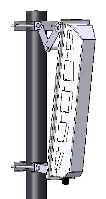
46 o For outdoor CPE s it is not as big a problem as you can run up to 50m of Ethernet cable to the external CPE. Other antennas or radio devices o CPE antennas must always be at least 1.5m away from other antennas like Wifi or TV antennas. CPE s could cause interference or receive interference from other transmitting antennas. o Also keep the minimum pole sizes in mind if you decide to use an existing mounting pole. The same minimum specifications must be met if you intend using an existing mounting pole Mounting pole and brackets It is very important to make sure that the right size pole and bracket are used for installations. If the pole is too long it could move too much in the wind and cause the beam of the antenna to miss the base station, or even worse, snap off completely. Below are the minimum specifications for a given mounting pole length. Up to 75cm: o 38mm aluminium pole o Small three-legged bracket, 15cm offset from wall Up to 2m: o 50mm aluminium pole, 1mm wall thickness o Medium three legged bracket, 25cm offset from wall Never attempt to use a pole that is longer than 2m. If you require more than 2m of pole to achieve clearance or for whatever reason, refer the situation to the Regional Radio Team Rawl bolts and other fasteners Rawl bolts are used to mount the three legged bracket to the wall. If these bolts fail for whatever reason, the whole antenna and pole will come off the wall and not only will the client lose their internet connection, it could possible damage vehicles, equipment, dogs and kids. It is important to note that the CPE antennas that you will install could have significant wind loading and will pull rawl bolts out of the wall relatively easily if they are not installed correctly. Below are the specifications required for a proper WiMAX installation. 46

47 Figure 20. Rawl bolt suitable for mounting brackets to walls Always use high quality rawl bolts, preferably well known brands like Rawl and Fisher. Use M8 10L rawl bolts o The correct size hole for these rawl bolts are 12mm o The correct depth of the hole is 55mm o Torque the bolt to 7.5Nm Figure 21. TIP : When inserting the rawl bolt sleeve into the hole, first screw the bolt in so that the tip protrudes from the sleeve. This will prevent dust from falling onto the thread and seizing up the bolt Drilling holes The single biggest problem with a hole in the wall is that it can t be undone or moved. For this reason it is vitally important that you get it right first time. Below are some tips on drilling proper holes for WiMAX installations. Measure/mark off where you intend drilling the holes. o o When drilling holes for bracket, make sure that you are not pushing the bracket too hard against the wall when marking the positions. Three legged brackets tend to spread open and will cause the pole to be skew. For three legged brackets, make sure the two holes that are on the same level are actually level. Use a spirit level to check this BEFORE drilling any holes. If they are not level, the pole will be skew. 47


48 Check the hole positions AGAIN. o Measure twice, drill once. Set the depth on the drill to the correct value. Figure 22. Setting the drill depth o NEVER DRILL ON GUT FEEL!!! Use a proper SDS drilling machine with depth adjustment for the holes. An SDS drill will give you more control and will drill much neater holes much faster than a normal hammer drill. o Use the correct size SDS drill bit Figure 23. SDS drills and drill bits o When drilling holes through a will, be careful that the hammer action does not remove large chunks of plaster from the other side of the wall. 4.2 Waterproofing Water ingress into antennas, cables and homes is one of the major problems in the installation industry. It is actually surprisingly hard to keep water from seeping into the minutest of holes and cracks. Although most of the equipment for outdoor use is designed to be weatherproof, a little bit of common sense and awareness will go a long way to keep the water out of your equipment. 48

49 4.2.1 Waterproofing Connectors One of the most common entries for water is found where the antenna is connected to the cable. Often this connection will not be inside a weatherproof enclosure and often it is assumed that a connector that is connected to a cable will be waterproof. There are some type of connectors that are designed to be waterproof to a degree, like the N-type connector, but even so it is still good practice to add an additional layer of protection around the connector. Water can generally slip in either directly between the two matching connectors, or it can seep through the crimped part behind the connector. It is therefore important that the connector be sealed off all the way to the cable itself, covering both connectors. The correct way to waterproof a connector pair is to use self-amalgamating tape. One such tape that is recommended is 3M Scotch 23 Rubber Tape. Normal insulation tape is NOT a selfamalgamating tape and should NOT be used to waterproof connectors! Instructions Figure 24. Scotch 23 self amalgamating tape for waterproofing connectors For an N-type connection, cut off a piece of tape that is about 15cm long. Start where the two connectors meet up and wind the tape around the connectors. The tape should be stretched to about 3 times its original length while winding it around the connector. Move your way towards the cable making sure that each winding overlaps about half of the previous winding. Once you ve reached the cable, turn around and repeat the process in the other direction until you reach the cable again. Make sure that the cable is covered a distance of about the width of the tape away from the connector. Finish the process at the same point where you started. 49

 is present at the hole. Example of a drip loop Figure 26.")
50 Figure 25. Example of a connector pair sealed with self-amalgamating tape Running the cable Water will often flow down a cable quite nicely. It is therefore important to keep this in mind when running the cable from the antenna into the building. Below are a few tips in this regard. Always mount an antenna in such a way that the cable leaves from the bottom of the antenna/cpe. Where the cable enters a building, make sure the cable makes a half loop BELOW the hole. Water will then drip off the cable instead of running right up against the hole and whatever seal (or shortage there-of) is present at the hole. Example of a drip loop Figure 26. Creating a drip loop before entering the building Strain relief Cables should never be allowed to simply hang from an antenna or external CPE. Normally connectors are not designed to take a lot of pulling force and they could easily be damaged if they are pulled hard. Even the weight of a cable hanging on the connector could damage the connector and/or antenna over longer periods. It is therefore necessary to strain relief any cables that comes out of an antenna or CPE. The preferred way of doing this is to use cable ties and tie the cable down to the mounting mast or 50
 the life time of the antenna.")
51 bracket as close to the antenna as possible. Be careful not to pull the cable too tight before tying it to the mast! Figure 27. Using a cable tie to strain relief a cable Also keep in mind that the cable ties that you are using will be standing in the sun for (hopefully) the life time of the antenna. Only use high quality cable ties! Many of the cheaper versions will perish within a few months and will simply fall off on its own. One brand of cable ties that works very well is Hellerman Tyton. Figure 28. High quality cable ties from Hellerman Tyton Running the cable neatly Once the cable leaves the antenna, it needs to run all the way to the CPE device in the building. Remember that the client will often measure the quality of your installation by the neatness of your 51

52 work rather than the actual signal strength and CINR. If a client is going to complain about your work, it will most likely be related to the way the cable was run/installed. So to save you the headaches of a complaining client, it is definitely worth getting it right first time. Below are a few tips in this regard. NEVER use a glue gun to fix a cable to a wall. Use a nail cable saddle. Use the correctly sized nail cable saddles to run the cable along a wall. o If you don t have the right size, drive to the nearest hardware shop an buy them. NEVER attempt to use a cable saddle that is too small or too big. A cable saddle that is too small will look ugly and will most likely damage the cable. A cable saddle that is too big will cause the cable to hang loose and will not look neat. Figure 29. Nail cable saddles used to run cables neatly Make sure the cable runs perfectly horizontally or vertically. Use a spirit level! o The human eye can spot an off-level cable to less than a degree. Where ever possible, run the cable along a corner of a wall or roof. This will make the installation look a lot neater. When going around corners, make sure that you do not bend the cable more than the specified bend radius. 4.3 Obstructions In the previous chapters we referred to the Fresnel zone and the impact on long distance links. In this section we are going to look in more detail on how to handle obstructions, especially close to the antenna, in more detail. It is important to remember that objects close to the antenna will also affect the performance of the antenna, even if it is not directly in the path of the antenna. 52

53 Figure 30. Clearance required close to the antenna This image shows the area in front of the antenna that needs to be clear for the antenna to work properly Walls and roofs Close to the antenna, one needs to make sure that the beam of the antenna will clear the roof and walls of the building, especially if the antenna is pointed parallel to the wall. Below are some examples of good and bad installations in terms of nearby obstructions. Figure 31. Roof interferes with the Fresnel zone of the antenna 53

54 Figure 32. Wall interferes with the Fresnel zone of the antenna In these two examples, the wall and the roof interfere with the Fresnel zone of the antenna and will thus block a part of the signal. Be careful!!! Mounting pole could be too long. 54

55 The last three examples show you some alternatives to the first two bad cases. Just be aware that the mounting pole could be too long in some cases, in which case you will have to find an alternative mounting position Trees The other major obstruction that is usually close to the installation site is trees and other vegetation. It is not advisable to try and go straight through a tree of any sorts, even if you area able to get a strong enough signal during your sight survey. Trees have a nasty habit of growing and changing over time and seasons, so you have no guarantee that your link will still be working in 6 month s time. If it is not possible to get clear line of sight to the required base station due to tree cover, the installation should be stopped and the situation referred to the Regional Radio Team. 4.4 Aligning the antenna It might sound relatively obvious, but it is important to aim the antenna in the direction of the base station. This is one of the factors that are often not done properly and can have a huge influence on the quality of the installation Beamwidth in practice We already covered radiation patterns and beamwidth in the earlier sections. In this section we are going to look at the implications in real life installations. The 20dBi flat panel antenna has a beam width of 20 degrees. This may sound like a lot, but keep in mind that this is the -3dB beam width. Normally we will try and get much closer to the maximum value than 3dB, typically we should be within 1dB of the maximum which means that the beam that we are working with is actually much narrower. 55
Practical Antennas and. Tuesday, March 4, 14
 Practical Antennas and Transmission Lines Goals Antennas are the interface between guided waves (from a cable) and unguided waves (in space). To understand the various properties of antennas, so as to
This Antenna Basics reference guide includes basic information about antenna types, how antennas work, gain, and some installation examples.
 Antenna Basics This Antenna Basics reference guide includes basic information about antenna types, how antennas work, gain, and some installation examples. What Do Antennas Do? Antennas transmit radio
Antenna Basics. Antennas. A guide to effective antenna use
 A guide to effective antenna use Antennas Antennas transmit radio signals by converting radio frequency electrical currents into electromagnetic waves. Antennas receive the signals by converting the electromagnetic
6 Radio and RF. 6.1 Introduction. Wavelength (m) Frequency (Hz) Unit 6: RF and Antennas 1. Radio waves. X-rays. Microwaves. Light
 Frequency (Hz) Unit 6: RF and Antennas 1. Radio waves. X-rays. Microwaves. Light") 6 Radio and RF Ref: http://www.asecuritysite.com/wireless/wireless06 6.1 Introduction The electromagnetic (EM) spectrum contains a wide range of electromagnetic waves, from radio waves up to X-rays (as
6 Radio and RF Ref: http://www.asecuritysite.com/wireless/wireless06 6.1 Introduction The electromagnetic (EM) spectrum contains a wide range of electromagnetic waves, from radio waves up to X-rays (as
Colubris Networks. Antenna Guide
 Colubris Networks Antenna Guide Creation Date: February 10, 2006 Revision: 1.0 Table of Contents 1. INTRODUCTION... 3 2. ANTENNA TYPES... 3 2.1. OMNI-DIRECTIONAL ANTENNA... 3 2.2. DIRECTIONAL ANTENNA...
Reading and working through Learn Networking Basics before this document will help you with some of the concepts used in wireless networks.
 Networking Learn Wireless Basics Introduction This document covers the basics of how wireless technology works, and how it is used to create networks. Wireless technology is used in many types of communication.
Project = An Adventure : Wireless Networks. Lecture 4: More Physical Layer. What is an Antenna? Outline. Page 1
 Project = An Adventure 18-759: Wireless Networks Checkpoint 2 Checkpoint 1 Lecture 4: More Physical Layer You are here Done! Peter Steenkiste Departments of Computer Science and Electrical and Computer
RoamAbout Outdoor Antenna Site Preparation Guide
 9033153 RoamAbout 802.11 Outdoor Antenna Site Preparation Guide Notice Notice Cabletron Systems reserves the right to make changes in specifications and other information contained in this document without
Antennas. and a bit physics. Was it not the God who wrote these signs, that have calmed alarm of my soul and have opened to me a secret of nature?
 Antennas and a bit physics. 2006/4/1 The famous "Maxwell Equations", a complete description of the EM field James Clerk Maxwell Was it not the God who wrote these signs, that have calmed alarm of my soul
Chapter 6 Antenna Basics. Dipoles, Ground-planes, and Wires Directional Antennas Feed Lines
 Chapter 6 Antenna Basics Dipoles, Ground-planes, and Wires Directional Antennas Feed Lines Some General Rules Bigger is better. (Most of the time) Higher is better. (Most of the time) Lower SWR is better.
Amateur Radio License. Propagation and Antennas
 Amateur Radio License Propagation and Antennas Todays Topics Propagation Antennas Propagation Modes Ground wave Low HF and below, ground acts as waveguide Line-of-Sight (LOS) VHF and above, radio waves
Technician Licensing Class. Antennas
 Technician Licensing Class Antennas Antennas A simple dipole mounted so the conductor is parallel to the Earth's surface is a horizontally polarized antenna. T9A3 Polarization is referenced to the Earth
Antennas and Propagation Chapters T4, G7, G8 Antenna Fundamentals, More Antenna Types, Feed lines and Measurements, Propagation
 Antennas and Propagation Chapters T4, G7, G8 Antenna Fundamentals, More Antenna Types, Feed lines and Measurements, Propagation =============================================================== Antenna Fundamentals
Multimedia Training Kit
 Multimedia Training Kit Antennas and Cables Alberto Escudero Pascual, IT+46 Goals Focus on explaining the losses in the link budget equation Introduce a set of types of antennas and cables How to make
Range Considerations for RF Networks
 TI Technology Days 2010 Range Considerations for RF Networks Richard Wallace Abstract The antenna can be one of the most daunting components of wireless designs. Most information available relates to large
Technician License Course Chapter 4. Lesson Plan Module 9 Antenna Fundamentals, Feed Lines & SWR
 Technician License Course Chapter 4 Lesson Plan Module 9 Antenna Fundamentals, Feed Lines & SWR The Antenna System Antenna: Transforms current into radio waves (transmit) and vice versa (receive). Feed
4 Antennas as an essential part of any radio station
 4 Antennas as an essential part of any radio station 4.1 Choosing an antenna Communicators quickly learn two antenna truths: Any antenna is better than no antenna. Time, effort and money invested in the
4/29/2012. General Class Element 3 Course Presentation. Ant Antennas as. Subelement G9. 4 Exam Questions, 4 Groups
 General Class Element 3 Course Presentation ti ELEMENT 3 SUB ELEMENTS General Licensing Class Subelement G9 Antennas and Feedlines 4 Exam Questions, 4 Groups G1 Commission s Rules G2 Operating Procedures
Module contents. Antenna systems. RF propagation. RF prop. 1
 Module contents Antenna systems RF propagation RF prop. 1 Basic antenna operation Dipole Antennas are specific to Frequency based on dimensions of elements 1/4 λ Dipole (Wire 1/4 of a Wavelength) creates
FCC Technician License Course
 FCC Technician License Course 2014-2018 FCC Element 2 Technician Class Question Pool Presented by: Tamiami Amateur Radio Club (TARC) WELCOME To the third of 4, 3-hour classes presented by TARC to prepare
Sebastian Büttrich, wire.less.dk edit: September 2009, Pokhara, Nepal. Shortened version of
 Antennas and Cables Sebastian Büttrich, wire.less.dk edit: September 2009, Pokhara, Nepal Shortened version of http://www.itrainonline.org/itrainonline/mmtk/wireless_en/08_antennas_cables/08_en_mmtk_wireless_antennas-cables_slides.odp
August, Antennas 101: A Course in RF Basics
 August, 2012 Antennas 101: A Course in RF Basics Antenna Basics Agenda: In today s training, we will go over a brief summary of the following topics at a basic level: Electromagnetic Waves Frequency and
1 Propagation in free space and the aperture antenna
 1 Propagation in free space and the aperture antenna This chapter introduces the basic concepts of radio signals travelling from one antenna to another. The aperture antenna is used initially to illustrate
Technician License. Course
 Technician License Course Technician License Course Chapter 4 Lesson Plan Module - 9 Antenna Fundamentals Feed Lines & SWR The Antenna System The Antenna System Antenna: Transforms current into radio waves
Intermediate Course (5) Antennas and Feeders
 Antennas and Feeders") Intermediate Course (5) Antennas and Feeders 1 System Transmitter 50 Ohms Output Standing Wave Ratio Meter Antenna Matching Unit Feeder Antenna Receiver 2 Feeders Feeder types: Coaxial, Twin Conductors
Intermediate Course (5) Antennas and Feeders 1 System Transmitter 50 Ohms Output Standing Wave Ratio Meter Antenna Matching Unit Feeder Antenna Receiver 2 Feeders Feeder types: Coaxial, Twin Conductors
advancing information transport systems
 BICSInews advancing information transport systems January/February 2007 PRESIDENT S MESSAGE 3 EXECUTIVE DIRECTOR MESSAGE 4 BICSI UPDATE 41-42 COURSE SCHEDULE 43-44 STANDARDS REPORT 45-46 Volume 28, Number
Link Budget Calculation
 Link Budget Calculation Training materials for wireless trainers This 60 minute talk is about estimating wireless link performance by using link budget calculations. It also introduces the Radio Mobile
F10F Series Wide band booster User s Manual
 F10F Series Wide band booster User s Manual Directory F10F Series Booster User s Manual 1. Abbreviations 2 2. Safety Warnings 2 3. Application 3 4. Introduction 4 5. System Characteristics 5 5.1. Features
Practical Antennas and
 Practical Antennas and Transmission Lines This talk covers antenna properties, transmission line characteristics, radio cable connectors and adapters, and shows examples of different kinds of commercial
Technician Licensing Class T9
 Technician Licensing Class T9 Amateur Radio Course Monroe EMS Building Monroe, Utah January 11/18, 2014 January 22, 2014 Testing Session Valid dates: July 1, 2010 June 30, 2014 Amateur Radio Technician
Cisco Aironet 2.4-GHz/5-GHz 8-dBi Directional Antenna (AIR-ANT2588P3M-N)
") Cisco Aironet.4-GHz/5-GHz 8-dBi Directional Antenna (AIR-ANT588P3M-N) This document outlines the specifications for the Cisco Aironet AIR-ANT588P3M-N.4/5-GHz 8-dBi 3-Port Directional Antenna with N-connectors
Cisco Aironet.4-GHz/5-GHz 8-dBi Directional Antenna (AIR-ANT588P3M-N) This document outlines the specifications for the Cisco Aironet AIR-ANT588P3M-N.4/5-GHz 8-dBi 3-Port Directional Antenna with N-connectors
ANTENNAS FEED POINTS. An antenna is a mechanical structure by which electromagnetic waves are sent out or received.
 ANTENNAS An antenna is a mechanical structure by which electromagnetic waves are sent out or received. An antenna accomplishes this by being made so that its structure will be resonant at the frequency
Exercise 1-3. Radar Antennas EXERCISE OBJECTIVE DISCUSSION OUTLINE DISCUSSION OF FUNDAMENTALS. Antenna types
 Exercise 1-3 Radar Antennas EXERCISE OBJECTIVE When you have completed this exercise, you will be familiar with the role of the antenna in a radar system. You will also be familiar with the intrinsic characteristics
Basic Radio Physics. Developed by Sebastian Buettrich. ItrainOnline MMTK 1
 Basic Radio Physics Developed by Sebastian Buettrich 1 Goals Understand radiation/waves used in wireless networking. Understand some basic principles of their behaviour. Apply this understanding to real
REFERENCE GUIDE External Antennas Guide. Tel: +44 (0) Fax: +44 (0)
 Fax: +44 (0)") REFERENCE GUIDE External s Guide Xirrus External s Guide Overview To optimize the overall performance of a Xirrus WLAN in an outdoor deployment it is important to understand how to maximize coverage with
REFERENCE GUIDE External s Guide Xirrus External s Guide Overview To optimize the overall performance of a Xirrus WLAN in an outdoor deployment it is important to understand how to maximize coverage with
Technician License. Course
 Technician License Course Technician License Course Chapter 4 Lesson Plan Module - 10 Practical Antennas The Dipole Most basic antenna The Dipole Most basic antenna The Dipole Total length is ½ wavelength
Cisco Aironet Omnidirectional Mast Mount Antenna (AIR-ANT2506)
") Cisco Aironet Omnidirectional Mast Mount Antenna (AIR-ANT2506) This document outlines the specifications, describes the omnidirectional mast mount antenna, and provides instructions for mounting it. Designed
Cisco Aironet Omnidirectional Mast Mount Antenna (AIR-ANT2506) This document outlines the specifications, describes the omnidirectional mast mount antenna, and provides instructions for mounting it. Designed
REFERENCE GUIDE External Antennas Guide 1
 REFERENCE GUIDE External s Guide 1 Xirrus External s Guide Overview To optimize the overall performance of a Xirrus WLAN in an outdoor deployment it is important to understand how to maximize coverage
Antenna Glossary. BEAMWIDTH The angle of signal coverage provided by an antenna. Beamwidth usually decreases as antenna gain increases.
 ADAPTIVE (SMART) ANTENNA An antenna system having circuit elements associated with its radiating elements such that one or more of the antenna properties are controlled by the received signal. ANTENNA
Antenna Fundamentals Basics antenna theory and concepts
 Antenna Fundamentals Basics antenna theory and concepts M. Haridim Brno University of Technology, Brno February 2017 1 Topics What is antenna Antenna types Antenna parameters: radiation pattern, directivity,
Cisco Aironet 13.5-dBi Yagi Mast Mount Antenna (AIR-ANT1949)
") Cisco Aironet 13.5-dBi Yagi Mast Mount Antenna (AIR-ANT1949) Overview This document describes the 13.5-dBi Yagi mast mount antenna and provides instructions for mounting it. The antenna operates in the
Cisco Aironet 13.5-dBi Yagi Mast Mount Antenna (AIR-ANT1949) Overview This document describes the 13.5-dBi Yagi mast mount antenna and provides instructions for mounting it. The antenna operates in the
The better WLAN Radio Network by an optimal Antenna System
 The better WLAN Radio Network by an optimal Antenna System BU Antennas ASY H&S Antennen mme / Pfad...ppt 1 www.hubersuhner.com www.hubersuhner.com The better radio network by optimal antennas What is an
Industrial Wireless Systems
 Application Considerations Don Pretty Principal Engineer Geometric Controls Inc Bethlehem, PA Sheet 1 Ethernet Dominates on the Plant Floor Sheet 2 Recognize Any of These? Sheet 3 Answers: 10 BASE 2 RG
Technician Licensing Class. Lesson 4. presented by the Arlington Radio Public Service Club Arlington County, Virginia
 Technician Licensing Class Lesson 4 presented by the Arlington Radio Public Service Club Arlington County, Virginia 1 Quiz Sub elements T6 & T7 2 Good Engineering Practice Sub element T8 3 A Basic Station
Outline / Wireless Networks and Applications Lecture 3: Physical Layer Signals, Modulation, Multiplexing. Cartoon View 1 A Wave of Energy
 Outline 18-452/18-750 Wireless Networks and Applications Lecture 3: Physical Layer Signals, Modulation, Multiplexing Peter Steenkiste Carnegie Mellon University Spring Semester 2017 http://www.cs.cmu.edu/~prs/wirelesss17/
Appendix A Decibels. Definition of db
 Appendix A Decibels Communication systems often consist of many different blocks, connected together in a chain so that a signal must travel through one after another. Fig. A-1 shows the block diagram
Planning a Microwave Radio Link
 8000 Lee Highway Falls Church, VA 22042 703-205-0600 www.ydi.com Planning a Microwave Radio Link By Michael F. Young President and CTO YDI Wireless Background Most installers know that clear line of sight
Antennas 101 Don t Be a 0.97 db Weakling! Ward Silver NØAX
 Antennas 101 Don t Be a 0.97 db Weakling! Ward Silver NØAX Overview Antennas 101 2 Overview Basic Antennas: Ground Plane / Dipole How Gain and Nulls are Formed How Phased Arrays Work How Yagis Work (simplified)
SWR myths and mysteries.
 SWR myths and mysteries. By Andrew Barron ZL3DW September 2012 This article will explain some of the often misunderstood facts about antenna SWR at HF and uncover some popular misconceptions. The questions
EMG4066:Antennas and Propagation Exp 1:ANTENNAS MMU:FOE. To study the radiation pattern characteristics of various types of antennas.
 OBJECTIVES To study the radiation pattern characteristics of various types of antennas. APPARATUS Microwave Source Rotating Antenna Platform Measurement Interface Transmitting Horn Antenna Dipole and Yagi
Session2 Antennas and Propagation
 Wireless Communication Presented by Dr. Mahmoud Daneshvar Session2 Antennas and Propagation 1. Introduction Types of Anttenas Free space Propagation 2. Propagation modes 3. Transmission Problems 4. Fading
The Physics of Radio By John White
 The Physics of Radio By John White Radio Bands and Channels The use of wireless devices is heavily regulated throughout the world. Each country has a government department responsible for deciding where
24. Antennas. What is an antenna. Types of antennas. Reciprocity
 4. Antennas What is an antenna Types of antennas Reciprocity Hertzian dipole near field far field: radiation zone radiation resistance radiation efficiency Antennas convert currents to waves An antenna
Technician License Course Chapter 4
 Technician License Course Chapter 4 Propagation, Basic Antennas, Feed lines & SWR K0NK 26 Jan 18 The Antenna System Antenna: Facilitates the sending of your signal to some distant station. Feed line: Connects
Improved Ionospheric Propagation With Polarization Diversity, Using A Dual Feedpoint Cubical Quad Loop
 Improved Ionospheric Propagation With Polarization Diversity, Using A Dual Feedpoint Cubical Quad Loop by George Pritchard - AB2KC ab2kc@optonline.net Introduction This Quad antenna project covers a practical
Antennas Demystified Antennas in Emergency Communications. Scott Honaker N7SS
 Antennas Demystified Antennas in Emergency Communications Scott Honaker N7SS Importance of Antennas Antennas are more important than the radio A $5000 TV with rabbit ears will have a lousy picture Antennas
Antenna Fundamentals
 HTEL 104 Antenna Fundamentals The antenna is the essential link between free space and the transmitter or receiver. As such, it plays an essential part in determining the characteristics of the complete
TACTICAL DIRECTORY ANTENNA DIAGRAM 3 INTRODUCTION LARGE OR SMALL INDOOR OR OUTDOOR EXTERNAL OR INTEGRATED US, EU, OR GLOBAL ENERGY FLOW
 TACTICAL DIRECTORY DIAGRAM 3 INTRODUCTION LARGE OR SMALL INDOOR OR OUTDOOR EXTERNAL OR INTEGRATED US, EU, OR GLOBAL ENERGY FLOW CIRCULAR OR LINEAR POLARIZATION DIAGRAM FAR FIELD OR NEAR FIELD FAR FIELD
Optimizing Your Stations Performance
 Optimizing Your Stations Performance A few hints / techniques, recommendations for getting the most RF out to the Antenna from your HF, VHF / UHF station. Tonights Presenters: Doug Theriault NO1D John
HP ProCurve 6.9/7.7dBi Dual Band Directional Antenna (J8999A) Guide
 Guide") HP ProCurve 6.9/7.7dBi Dual Band Directional Antenna (J8999A) Guide SAFETY The HP ProCurve J8999A and all associated equipment should be installed in accordance with applicable local and national electrical
HP ProCurve 6.9/7.7dBi Dual Band Directional Antenna (J8999A) Guide SAFETY The HP ProCurve J8999A and all associated equipment should be installed in accordance with applicable local and national electrical
Lesson 11: Antennas. Copyright Winters Version 1.0. Preparation for Amateur Radio Technician Class Exam
 Lesson 11: Antennas Preparation for Amateur Radio Technician Class Exam Topics Antenna ½ wave Dipole antenna ¼ wave Vertical antenna Antenna polarization Antenna location Beam antennas Test Equipment Exam
Antennas and Propagation. Chapter 5
 Antennas and Propagation Chapter 5 Introduction An antenna is an electrical conductor or system of conductors Transmission - radiates electromagnetic energy into space Reception - collects electromagnetic
Antennas & Propagation. CSG 250 Fall 2007 Rajmohan Rajaraman
 Antennas & Propagation CSG 250 Fall 2007 Rajmohan Rajaraman Introduction An antenna is an electrical conductor or system of conductors o Transmission - radiates electromagnetic energy into space o Reception
Dr. John S. Seybold. November 9, IEEE Melbourne COM/SP AP/MTT Chapters
 Antennas Dr. John S. Seybold November 9, 004 IEEE Melbourne COM/SP AP/MTT Chapters Introduction The antenna is the air interface of a communication system An antenna is an electrical conductor or system
The Basics of Signal Attenuation
 The Basics of Signal Attenuation Maximize Signal Range and Wireless Monitoring Capability CHESTERLAND OH July 12, 2012 Attenuation is a reduction of signal strength during transmission, such as when sending
Site Surveying and Antenna Mounting
 Site Surveying and Antenna Mounting Abdus Salam ICTP, February 2005 School on Digital Radio Communications for Research and Training in Developing Countries Ermanno Pietrosemoli Latin American Networking
REFERENCE GUIDE External Antennas Guide 1
 REFERENCE GUIDE External s Guide 1 Xirrus External s Guide Overview To optimize the overall performance of a Xirrus WLAN in an outdoor deployment it is important to understand how to maximize coverage
87.5 TO MHz BAND II 2 WAY 4.8dBi STACKED DIPOLE ANTENNA
 87.5 TO 108.0 MHz BAND II 2 WAY 4.8dBi STACKED DIPOLE ANTENNA 1. INTRODUCTION 3 1.1. GENERAL INFORMATION 3 1.2. UNPACKING AND CHECKING 3 1.3. WARRANTY 3 1.4. USER SAFETY RESPONSIBILITY 4 1.5. INSTALLATION
BASICS OF ANTENNAS Lecture Note 1
 BASICS OF ANTENNAS Lecture Note 1 INTRODUCTION Antennas are devices that are capable of launching RF (radio frequency) energy into space and detect it as well. How well an antenna is able to launch RF
You will need the following pieces of equipment to complete this experiment: Wilkinson power divider (3-port board with oval-shaped trace on it)
") UNIVERSITY OF TORONTO FACULTY OF APPLIED SCIENCE AND ENGINEERING The Edward S. Rogers Sr. Department of Electrical and Computer Engineering ECE422H1S: RADIO AND MICROWAVE WIRELESS SYSTEMS EXPERIMENT 1:
UNIVERSITY OF TORONTO FACULTY OF APPLIED SCIENCE AND ENGINEERING The Edward S. Rogers Sr. Department of Electrical and Computer Engineering ECE422H1S: RADIO AND MICROWAVE WIRELESS SYSTEMS EXPERIMENT 1:
Antennas and Propagation
 Antennas and Propagation Chapter 5 Introduction An antenna is an electrical conductor or system of conductors Transmission - radiates electromagnetic energy into space Reception - collects electromagnetic
Basic radio physics. Sebastian Büttrich, NSRC/ITU/wire.less.dk edit: June
 Basic radio physics Sebastian Büttrich, NSRC/ITU/wire.less.dk edit: June 2011 http://creativecommons.org/licenses/by-nc-sa/3.0/ Electromagnetic Fields Electromagnetic forces act between electric charges
IR Remote Control. Jeffrey La Favre. January 26, 2015
 1 IR Remote Control Jeffrey La Favre January 26, 2015 Do you have a remote control for your television at home? If you do, it is probably an infrared remote (IR). When you push a button on the IR remote,
Antennas and Propagation. Chapter 5
 Antennas and Propagation Chapter 5 Introduction An antenna is an electrical conductor or system of conductors Transmission - radiates electromagnetic energy into space Reception - collects electromagnetic
CHAPTER 5 THEORY AND TYPES OF ANTENNAS. 5.1 Introduction
 CHAPTER 5 THEORY AND TYPES OF ANTENNAS 5.1 Introduction Antenna is an integral part of wireless communication systems, considered as an interface between transmission line and free space [16]. Antenna
Milton Keynes Amateur Radio Society (MKARS)
") Milton Keynes Amateur Radio Society (MKARS) Intermediate Licence Course Feeders Antennas Matching (Worksheets 31, 32 & 33) MKARS Intermediate Licence Course - Worksheet 31 32 33 Antennas Feeders Matching
Milton Keynes Amateur Radio Society (MKARS) Intermediate Licence Course Feeders Antennas Matching (Worksheets 31, 32 & 33) MKARS Intermediate Licence Course - Worksheet 31 32 33 Antennas Feeders Matching
Propagation mechanisms
 RADIO SYSTEMS ETIN15 Lecture no: 2 Propagation mechanisms Ove Edfors, Department of Electrical and Information Technology Ove.Edfors@eit.lth.se Contents Short on db calculations Basics about antennas Propagation
Wireless Point to Point Frequently Asked Questions
 Wireless Point to Point Frequently Asked Questions Document ID: 9217 Contents Introduction What type(s) of antennas can I use with my system? Do the antennas for both ends of my link need to be the same
CS-435 spring semester Network Technology & Programming Laboratory. Stefanos Papadakis & Manolis Spanakis
 CS-435 spring semester 2016 Network Technology & Programming Laboratory University of Crete Computer Science Department Stefanos Papadakis & Manolis Spanakis CS-435 Lecture preview Wireless Networking
Antennas and Propagation
 CMPE 477 Wireless and Mobile Networks Lecture 3: Antennas and Propagation Antennas Propagation Modes Line of Sight Transmission Fading in the Mobile Environment Introduction An antenna is an electrical
stacking broadside collinear
 stacking broadside collinear There are three primary types of arrays, collinear, broadside, and endfire. Collinear is pronounced co-linear, and we may think it is spelled colinear, but the correct spelling
M2 Antenna Systems, Inc. Model No: 2M7
 M2 Antenna Systems, Inc. Model No: 2M7 SPECIFICATIONS: Model... 2M7 Frequency Range... 144 To 148 MHz *Gain... 12.3 dbi Front to back... 20 db Typical Beamwidth... E=43 H=50 Feed type... T Match Feed Impedance....
Antenna Fundamentals. Microwave Engineering EE 172. Dr. Ray Kwok
 Antenna Fundamentals Microwave Engineering EE 172 Dr. Ray Kwok Reference Antenna Theory and Design Warran Stutzman, Gary Thiele, Wiley & Sons (1981) Microstrip Antennas Bahl & Bhartia, Artech House (1980)
The VK3UM Radiation and System Performance Calculator
 The VK3UM Radiation and System Performance Calculator 1. Disclaimer... 2 2. Background... 2 3. Calculations... 2 4. Features... 2 5. Default Parameters... 3 6. Parameter Description... 4 7. On Axis Exclusion
CHAPTER 8 ANTENNAS 1
 CHAPTER 8 ANTENNAS 1 2 Antennas A good antenna works A bad antenna is a waste of time & money Antenna systems can be very inexpensive and simple They can also be very expensive 3 Antenna Considerations
Welcome to EnGenius Versatile Wireless Networking Applications and Configurations - Part 1 Outdoor Wireless Networking Products
 Welcome to EnGenius Versatile Wireless Networking Applications and Configurations - Part 1 Outdoor Wireless Networking Products Topics About Engenius Key Specifications 802.11 Standards IP Rating PoE Transmit
SPECIAL SPECIFICATION 6574 Low Power Wireless Modem
 2004 Specifications CSJ 1068-04-126, etc. SPECIAL SPECIFICATION 6574 Low Power Wireless Modem 1. Description. This work shall consist of furnishing and supplying a Low Power Wireless Modem at the locations
Antennas and Propagation
 Mobile Networks Module D-1 Antennas and Propagation 1. Introduction 2. Propagation modes 3. Line-of-sight transmission 4. Fading Slides adapted from Stallings, Wireless Communications & Networks, Second
4/25/2012. Supplement T9. 2 Exam Questions, 2 Groups. Amateur Radio Technician Class T9A: T9A: T9A: T9A:
 Amateur Radio Technician Class Element 2 Course Presentation ti ELEMENT 2 SUB-ELEMENTS Technician Licensing Class Supplement T9 Antennas, Feedlines 2 Exam Questions, 2 Groups T1 - FCC Rules, descriptions
IRIDIUM ACTIVE ANTENNA - AA511
 OVERVIEW Iridium satphones were originally designed to operate with a passive antenna, either an element attached directly to the handset, or a remote aerial connected with a short length of coaxial cable.
Antenna Performance. Antenna Performance... 3 Gain... 4 Radio Power and the FCC... 6 Link Margin Calculations... 7 The Banner Way... 8 Glossary...
 Antenna Performance Antenna Performance... 3 Gain... 4 Radio Power and the FCC... 6 Link Margin Calculations... 7 The Banner Way... 8 Glossary... 9 06/15/07 135765 Introduction In this new age of wireless
The Benefits of BEC s Antenna Design
 The Benefits of BEC s Antenna Design Overview The explosive growth of wireless data communications is fast emerging with high peak data rates, which require superior antenna performance and design to support
Model 3140B BiConiLog Antenna User Manual
 Model 3140B BiConiLog Antenna User Manual Model 3140B mounted onto a 7-TR tripod (not included) ETS-Lindgren L.P. reserves the right to make changes to any product described herein in order to improve
Antennas Prof. Girish Kumar Department of Electrical Engineering Indian Institute of Technology, Bombay. Module 2 Lecture - 10 Dipole Antennas-III
 Antennas Prof. Girish Kumar Department of Electrical Engineering Indian Institute of Technology, Bombay Module 2 Lecture - 10 Dipole Antennas-III Hello, and welcome to todays lecture on Dipole Antenna.
Wireless LAN RF Design Fundamentals
 Wireless LAN RF Design Fundamentals Page 1 Wireless LAN RF Design Fundamentals Sometimes we just have to return to the basics. This White Paper is just that a blast back to the past back to the early days
Microair Avionics Pty Ltd ABN VHF Aerial Installation FAQ
 Pty Ltd ABN 92 091 040 032 P O Box 5532 Airport Drive Bundaberg West Queensland 4670 Australia Phone: Fax: Email: Web: 07 4155 3048 +61 7 4155 3048 07 4155 3049 +61 7 4155 3049 support@microair.com.au
College of information Technology Department of Information Networks Telecommunication & Networking I Chapter DATA AND SIGNALS 1 من 42
 3.1 DATA AND SIGNALS 1 من 42 Communication at application, transport, network, or data- link is logical; communication at the physical layer is physical. we have shown only ; host- to- router, router-to-
Feed Line Currents for Neophytes.
 Feed Line Currents for Neophytes. This paper discusses the sources of feed line currents and the methods used to control them. During the course of this paper two sources of feed line currents are discussed:
ANTENNAS. I will mostly be talking about transmission. Keep in mind though, whatever is said about transmission is true of reception.
 Reading 37 Ron Bertrand VK2DQ http://www.radioelectronicschool.com ANTENNAS The purpose of an antenna is to receive and/or transmit electromagnetic radiation. When the antenna is not connected directly
The Reverse Polarity TNC(m) RF connector can be easily secured or removed from equipment in the field by a single gloved hand, no tools required.
 RF connector can be easily secured or removed from equipment in the field by a single gloved hand, no tools required.") Overview Southwest Antennas is a half wave dipole omni antenna with a frequency range of 1.35 to 1.40 GHz and 2.15 dbi of peak gain. This product features an integrated RF bandpass filter to help eliminate
Overview Southwest Antennas is a half wave dipole omni antenna with a frequency range of 1.35 to 1.40 GHz and 2.15 dbi of peak gain. This product features an integrated RF bandpass filter to help eliminate