Industrial Wireless Systems
|
|
|
- Ethan Cunningham
- 5 years ago
- Views:
Transcription
1 Application Considerations Don Pretty Principal Engineer Geometric Controls Inc Bethlehem, PA Sheet 1


2 Ethernet Dominates on the Plant Floor Sheet 2


3 Recognize Any of These? Sheet 3
4 Answers: 10 BASE 2 RG 58/U (Thin Ethernet) Thinnet NIC 50 Ω Terminator AB Pyramid Integrator Ethernet Interface Sheet 4

5 Today s wireless network Sheet 5
6 Workshop Goals Wireless communication terminology Radio system hardware Wireless application planning and design Functional Requirements Site Requirements Topology Configuration System Gain Calculations Review of Application Examples Sheet 6
7 Brief Discussion of Radio Terminology Technology Signal Strength Gain Radio Hardware Components Transceiver Antenna Sheet 7
8 THE BASICS SIGNAL GAIN Gain is a term used to quantify the transmission and reception characteristics of radio components. Gain is a ratio of device power relative to a reference power of 1 mw (device power mw / 1 mw = device power). Gain is expressed in decibels (db) which is a logarithmic value. Sheet 8
9 THE BASICS SIGNAL GAIN Gain db = 10 log 10 (device power mw /1 mw ) or Gain db = 10 log 10 (device power) Sheet 9
10 Amplifier Gain dbm When comparing the relative power or sensitivity of a radio amplifier, the term gain expressed as dbm (decibel relative to milliwatt) is used. Example 1 A radio device transmits an amplified signal with a power output of 1W at the antenna connection. What is the radio transmitter s gain in dbm? Using the formula above: Gain = 10 log 10 (device power mw / 1 mw ) = 10 log 10 (1000 mw / 1 mw ) = 10 log 10 (1000) = 10(3) = 30dBm Sheet 10
11 Amplifier Gain Example 2 A radio receiver circuit is sensitive to an incoming signal with a power level of 10 pw. What is the receiver s gain in dbm? Using the formula above: Gain = 10 log 10 (device power mw / 1 mw ) = 10 log 10 (10 pw / 1 mw ) = 10 log 10 (10 pw / pw ) = 10 log 10 ( ) = 10(-9) = -90dBm Sheet 11
 is used. The theoretical gain of an isotropic antenna = 10 log 10 (1) = 10*0 = 0 dbi.")
12 Antenna Gain dbi (Isotropic) Theoretical Isotropic Antenna with EM Field of 1 mw When comparing antenna focusing characteristics using the 1 mw Isotropic reference, the term gain expressed as dbi (decibel relative to Isotropic) is used. The theoretical gain of an isotropic antenna = 10 log 10 (1) = 10*0 = 0 dbi. Sheet 12

 = 10*0.215 = 2.15 dbi. The term gain expressed as dbd (decibel relative to dipole) is used.")
13 Antenna Gain dbd (Dipole) Dipole Antenna with EM Field of 1.64 mw The closest real antenna that exhibits isotropic characteristics is a simple two wire dipole. The gain of a dipole relative to an isotropic reference = 10 log 10 (1.64 mw / 1 mw ) = 10 log 10 (1.64) = 10*0.215 = 2.15 dbi. The term gain expressed as dbd (decibel relative to dipole) is used. 0 dbd = 2.15 dbi, or gain dbi = gain dbd Sheet 13
14 Unlicensed Radio Frequencies The FCC allocates a range of frequency bands designated Industrial, Medical, and Scientific (ISM) that do not require licensing. These bands 900 MHz ( ), 2.4 GHz ( ), and 5.8 GHz ( ) at a maximum power output of 30dBm. Sheet 14

15 Block Diagram of Radio Components Sheet 15
16 Understanding Radio Antenna Systems EM transmission through an antenna is analogous to light traveling through an optical lens. The lens does not add to the quantity of light but acts to focus the available light to increase the observed intensity at different locations. An antenna acts to focus as well as be sensitive to RF energy in a specific pattern. Antenna gain is a measure of the signal focus. Antennas are typically designed to provide either uniform or directional sensitivity. Sheet 16
17 Yagi Antenna A Yagi antenna design will generate and be sensitive to RF energy in a focused pattern which is parallel to the direction and in the same plane as the antenna is mounted. Because the radiation pattern is planer, two Yagi antennas should always be mounted in the same orientation. Sheet 17

18 Yagi Antenna EM Dispersion vs. db Sheet 18
19 Omni Antenna An Omni-directional antenna is designed to provide sensitivity that is in a uniform radial pattern in the plane perpendicular to the direction the antenna is mounted. Sheet 19

20 Omni Antenna EM Dispersion vs. db A higher gain Omni antenna will have a narrower sensitivity in the vertical plane. Sheet 20
21 Radio Transceiver Frequency 900 MHz Range up to 40 miles clear line of site or 1500 ft w/obstacles penetration, data rate Kbps. 5.8 GHz Range up to 40 miles clear line of site, no obstacle penetration, data rate up to 10 Mbps. 2.4 GHz Used predominately for indoor WI-FI. Sheet 21

22 900 MHz Obstacle Penetration Sheet 22
23 5.8 GHz Clear Line of Site Drive a bus through the path 5.8GHz 40 Miles is possible Sheet 23
24 Design Functional Considerations What s the application (I/O control, SCADA, video surveillance)? How many remote locations must be connected? What protocols are already in use? Will this system be attended or unattended/fully automated? Sheet 24
25 Design Bandwidth Considerations On-line PLC programming ( Kb) Video surveillance (800Kb w/mpeg4 compression) LAN/WAN bridging (10Mb 100 Mb) Sheet 25
26 Design Site Survey System topology based on number and location of communicating devices Distance and clarity of sight between communicating devices/systems Existing wireless systems and or other RF sources at the site Sheet 26

27 Site Survey Tools Google Earth Sheet 27

28 Site Survey Tools Frequency Spectrum Analyzer Sheet 28
29 System Design Point to Point Topology Sheet 29
30 System Design Point to Multipoint Topology Usable bandwidth is reduced by number of remote clients Sheet 30

31 System Design Alternate Point to Multipoint Usable bandwidth is available to each remote client Sheet 31
32 System Design System Link Budget Once the overall design strategy has been determined, selection of radio hardware requires an estimation of the overall wireless system gains and losses. Each component of the system will be accounted for in a Link Budget calculation as follows: Calculated Received Gain = Transmitter Gain + Antenna 1 Gain + Antenna 2 Gain Free Space Loss Component Loss. Sheet 32
33 System Design Hardware Gains Transmitter (amplifier) gain is the power output of the transmitter section in decibels dbm. This will be specified by the manufacturer. Antenna gain is the focusing characteristic. This will be specified by the manufacturer for a given antenna design in either units of dbi or dbd. Remember that if a dbd gain is provided, the value 2.15 db must be added to yield an equivalent dbi gain. Sheet 33
34 System Design Free Space Loss Free space loss is the physical loss of electro-magnetic energy during propagation. The equation used by radio engineers to estimate the free space loss between two isotropic antennas is L = 20 Log 10 (4πd/λ). L is the power loss in dbi. The equation simplifies to L = 20 Log 10 (Freq MHz ) + 20 Log 10 (Distance miles ) Sheet 34
35 System Design Component Loss The antenna s physical interface to the transceiver is a critical component that must be accounted for during the system design process. Each connecting device (cable, adaptor, etc) will act to attenuate or decrease the overall gain of the antenna system. The attenuation gain specifications for each component are typically provided by their manufacturer in units of dbi or dbd. Cable attenuation gain specifications are given in units of db per unit cable length. Sheet 35
36 System Design Safety Margin Once the Calculated Received Gain is obtained, it is compared to the radio receiver sensitivity specification, which is supplied by the radio manufacturer. Calculated Safety Margin = Calculated Received Power Receiver Hardware Sensitivity. Each radio manufacturer will specify a safety margin value which is a minimum performance comfort zone. The calculated safety margin should be manufacturer specified safety margin. Sheet 36
37 System Design Hardware Selection The results of the Link Budget calculation will dictate the maximum estimated distance between any two antennas at a given radio frequency. Distance can be increased by selection of a higher gain antenna. It s important to remember that FCC regulations restrict the maximum forward gain of any unlicensed radio transmitter not to exceed 30 dbm. It s the responsibility of the designer to ensure that these rules are enforced. Sheet 37
38 . Sheet 38
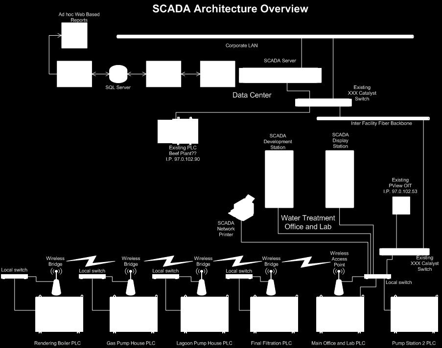
39 SCADA Application Challenges: Point to Multipoint configuration reduced overall bandwidth for each remote PLC system Large cellular array on the site premises caused interference Existing I/O telemetry system caused interference Resulting communication errors further reduced overall system bandwidth Solutions: Background noise and number of radios hampered the throughput of the system. Configured the sever PC to provide a clock synchronization update event once per day for all PLC s and workstations. Used each PLC system to pre-process data and events to be collected by creating a time stamp and storing data entries in a logical memory stack. These stacks were unloaded to the server database when bandwidth conditions were favorable. Sheet 39


40 Application Examples Attended Conveyor Control Mobile attended system with dedicated Access Point I/O radio and multiple remote push button stations Allow truckers to start and stop coal loading conveyor from within vehicle cab Sheet 40
41 Application Examples - Remote Pump Station Wireless Pump Control Circuit.pdf Sheet 41
42 QUESTIONS Sheet 42
Antenna Performance. Antenna Performance... 3 Gain... 4 Radio Power and the FCC... 6 Link Margin Calculations... 7 The Banner Way... 8 Glossary...
 Antenna Performance Antenna Performance... 3 Gain... 4 Radio Power and the FCC... 6 Link Margin Calculations... 7 The Banner Way... 8 Glossary... 9 06/15/07 135765 Introduction In this new age of wireless
Planning Your Wireless Transportation Infrastructure. Presented By: Jeremy Hiebert
 Planning Your Wireless Transportation Infrastructure Presented By: Jeremy Hiebert Agenda Agenda o Basic RF Theory o Wireless Technology Options o Antennas 101 o Designing a Wireless Network o Questions
This Antenna Basics reference guide includes basic information about antenna types, how antennas work, gain, and some installation examples.
 Antenna Basics This Antenna Basics reference guide includes basic information about antenna types, how antennas work, gain, and some installation examples. What Do Antennas Do? Antennas transmit radio
Antenna Basics. Antennas. A guide to effective antenna use
 A guide to effective antenna use Antennas Antennas transmit radio signals by converting radio frequency electrical currents into electromagnetic waves. Antennas receive the signals by converting the electromagnetic
The Physics of Radio By John White
 The Physics of Radio By John White Radio Bands and Channels The use of wireless devices is heavily regulated throughout the world. Each country has a government department responsible for deciding where
Link Budget Calculation
 Link Budget Calculation Training materials for wireless trainers This 60 minute talk is about estimating wireless link performance by using link budget calculations. It also introduces the Radio Mobile
Colubris Networks. Antenna Guide
 Colubris Networks Antenna Guide Creation Date: February 10, 2006 Revision: 1.0 Table of Contents 1. INTRODUCTION... 3 2. ANTENNA TYPES... 3 2.1. OMNI-DIRECTIONAL ANTENNA... 3 2.2. DIRECTIONAL ANTENNA...
CSNT 180 Wireless Networking. Chapter 4 Radio Frequency (RF) Fundamentals for Wireless LAN Technology
 Fundamentals for Wireless LAN Technology") CSNT 180 Wireless Networking Chapter 4 Radio Frequency (RF) Fundamentals for Wireless LAN Technology Norman McEntire norman.mcentire@servin.com Founder, Servin Corporation, http://servin.com Technology
CSNT 180 Wireless Networking Chapter 4 Radio Frequency (RF) Fundamentals for Wireless LAN Technology Norman McEntire norman.mcentire@servin.com Founder, Servin Corporation, http://servin.com Technology
AW900i. User s Manual. Point-to-point. Industrial-grade, ultra-long-range 900 MHz non-line-of-sight wireless Ethernet systems
 Point-to-point Industrial-grade, ultra-long-range 900 MHz non-line-of-sight wireless Ethernet systems Non-line-of-sight :: 900 MHz Thank you for your purchase of the point-to-point wireless Ethernet bridge.
6 Radio and RF. 6.1 Introduction. Wavelength (m) Frequency (Hz) Unit 6: RF and Antennas 1. Radio waves. X-rays. Microwaves. Light
 Frequency (Hz) Unit 6: RF and Antennas 1. Radio waves. X-rays. Microwaves. Light") 6 Radio and RF Ref: http://www.asecuritysite.com/wireless/wireless06 6.1 Introduction The electromagnetic (EM) spectrum contains a wide range of electromagnetic waves, from radio waves up to X-rays (as
6 Radio and RF Ref: http://www.asecuritysite.com/wireless/wireless06 6.1 Introduction The electromagnetic (EM) spectrum contains a wide range of electromagnetic waves, from radio waves up to X-rays (as
Take These Ten Steps to Ensure Wireless Success
 The Ten Commandments of Wireless Communications Take These Ten Steps to Ensure Wireless Success 724-746-5500 blackbox.com Table of Contents 1. Thou shalt know thy dbm and recall thy high school logarithms...
Presentation Title Subhead Date
 Getting The Most Out Of Your Wireless Mics Presentation Title Subhead Date Best Practices: Antennas, RF Coordination & Hardware Dave Mendez Senior Market Development Specialist The Wisdom of Dilbert Antennas:
Licensed vs Unlicensed Microwave Technology. Overview of Wireless John Dolmetsch
 Licensed vs Unlicensed Microwave Technology Wireless Topics Common licensed and unlicensed frequencies Frequencies and Ranges Indoor Wireless Technologies Licensed vs. Unlicensed Frequencies Mobile Applications
UNDER STANDING RADIO FREQUENCY Badger Meter, Inc.
 UNDER STANDING RADIO FREQUENCY UNDERSTANDING RADIO FREQUENCY Regional Sales Meeting March 1-2, 2011 Brian Fiut Sr. Product Manager Itron Inc. Liberty Lake, WA August 25, 2010 RADIO PROPAGATION Radio consists
Digi-Wave Technology Williams Sound Digi-Wave White Paper
 Digi-Wave Technology Williams Sound Digi-Wave White Paper TECHNICAL DESCRIPTION Operating Frequency: The Digi-Wave System operates on the 2.4 GHz Industrial, Scientific, and Medical (ISM) Band, which is
Planning a Microwave Radio Link
 8000 Lee Highway Falls Church, VA 22042 703-205-0600 www.ydi.com Planning a Microwave Radio Link By Michael F. Young President and CTO YDI Wireless Background Most installers know that clear line of sight
Know Your Options: Selecting the Right Remote Site Wireless Communications Technology for Collection & Reuse Distribution Systems
 Know Your Options: Selecting the Right Remote Site Wireless Communications Technology for Collection & Reuse Distribution Systems Standards Certification Education & Training Publishing Conferences & Exhibits
Vehicle Networks. Wireless communication basics. Univ.-Prof. Dr. Thomas Strang, Dipl.-Inform. Matthias Röckl
 Vehicle Networks Wireless communication basics Univ.-Prof. Dr. Thomas Strang, Dipl.-Inform. Matthias Röckl Outline Wireless Signal Propagation Electro-magnetic waves Signal impairments Attenuation Distortion
Founded 1990 Located in Lancaster NY (near Buffalo) Systems integration and wireless technology development history.
 Systems integration and wireless technology development history.") Founded 1990 Located in Lancaster NY (near Buffalo) Systems integration and wireless technology development history. Acquired assets and exclusive rights to Aria Wireless and GLB Electronics product line
Founded 1990 Located in Lancaster NY (near Buffalo) Systems integration and wireless technology development history. Acquired assets and exclusive rights to Aria Wireless and GLB Electronics product line
Designing a Wireless Network
 Designing a Wireless Network Steps / Considerations / Do s & Don t s Standards Certification Education & Training Publishing Conferences & Exhibits Patrick Ho Director, System Solutions, Eaton 2015 ISA
Using the epmp Link Budget Tool
 Using the epmp Link Budget Tool The epmp Series Link Budget Tool can offer a help to determine the expected performances in terms of distances of a epmp Series system operating in line-of-sight (LOS) propagation
REFERENCE GUIDE External Antennas Guide 1
 REFERENCE GUIDE External s Guide 1 Xirrus External s Guide Overview To optimize the overall performance of a Xirrus WLAN in an outdoor deployment it is important to understand how to maximize coverage
Announcements : Wireless Networks Lecture 3: Physical Layer. Bird s Eye View. Outline. Page 1
 Announcements 18-759: Wireless Networks Lecture 3: Physical Layer Please start to form project teams» Updated project handout is available on the web site Also start to form teams for surveys» Send mail
Welcome to EnGenius Versatile Wireless Networking Applications and Configurations - Part 1 Outdoor Wireless Networking Products
 Welcome to EnGenius Versatile Wireless Networking Applications and Configurations - Part 1 Outdoor Wireless Networking Products Topics About Engenius Key Specifications 802.11 Standards IP Rating PoE Transmit
peculiarities of radio devices
 Rudi van Drunen peculiarities of radio devices Rudi van Drunen is a senior UNIX systems consultant with Competa IT B.V. in The Netherlands. He also has his own consulting company, Xlexit Technology, doing
REFERENCE GUIDE External Antennas Guide. Tel: +44 (0) Fax: +44 (0)
 Fax: +44 (0)") REFERENCE GUIDE External s Guide Xirrus External s Guide Overview To optimize the overall performance of a Xirrus WLAN in an outdoor deployment it is important to understand how to maximize coverage with
REFERENCE GUIDE External s Guide Xirrus External s Guide Overview To optimize the overall performance of a Xirrus WLAN in an outdoor deployment it is important to understand how to maximize coverage with
advancing information transport systems
 BICSInews advancing information transport systems January/February 2007 PRESIDENT S MESSAGE 3 EXECUTIVE DIRECTOR MESSAGE 4 BICSI UPDATE 41-42 COURSE SCHEDULE 43-44 STANDARDS REPORT 45-46 Volume 28, Number
Wireless replacement for cables in CAN Network Pros and Cons. by Derek Sum
 Wireless replacement for cables in CAN Network Pros and Cons by Derek Sum TABLE OF CONTENT - Introduction - Concept of wireless cable replacement - Wireless CAN cable hardware - Real time performance and
The LoRa Protocol. Overview. Interference Immunity. Technical Brief AN205 Rev A0
 Technical Brief AN205 Rev A0 The LoRa Protocol By John Sonnenberg Raveon Technologies Corp Overview The LoRa (short for Long Range) modulation scheme is a modulation technique combined with a data encoding
The Basics of Signal Attenuation
 The Basics of Signal Attenuation Maximize Signal Range and Wireless Monitoring Capability CHESTERLAND OH July 12, 2012 Attenuation is a reduction of signal strength during transmission, such as when sending
Data and Computer Communications. Tenth Edition by William Stallings
 Data and Computer Communications Tenth Edition by William Stallings Data and Computer Communications, Tenth Edition by William Stallings, (c) Pearson Education - Prentice Hall, 2013 Wireless Transmission
Wireless LAN RF Design Fundamentals
 Wireless LAN RF Design Fundamentals Page 1 Wireless LAN RF Design Fundamentals Sometimes we just have to return to the basics. This White Paper is just that a blast back to the past back to the early days
Wireless System Characteristics
 Wireless System Characteristics Antennas designed by Mobile Mark are used by commercial wireless system integrators in countless applications and settings. Experience in this area has given our company
CS263: Wireless Communications and Sensor Networks
 CS263: Wireless Communications and Sensor Networks Matt Welsh Lecture 3: Antennas, Propagation, and Spread Spectrum September 30, 2004 2004 Matt Welsh Harvard University 1 Today's Lecture Antennas and
SEL-3060 Ethernet Radio Data Sheet
 SEL-3060 Ethernet Radio Data Sheet Wireless LAN Extension Major Features and Benefits Two Operating Modes Provide Flexibility. Supports point-to-point radio operation for higher performance and point-to-multipoint
ZigBee Propagation Testing
 ZigBee Propagation Testing EDF Energy Ember December 3 rd 2010 Contents 1. Introduction... 3 1.1 Purpose... 3 2. Test Plan... 4 2.1 Location... 4 2.2 Test Point Selection... 4 2.3 Equipment... 5 3 Results...
Module contents. Antenna systems. RF propagation. RF prop. 1
 Module contents Antenna systems RF propagation RF prop. 1 Basic antenna operation Dipole Antennas are specific to Frequency based on dimensions of elements 1/4 λ Dipole (Wire 1/4 of a Wavelength) creates
Outline / Wireless Networks and Applications Lecture 3: Physical Layer Signals, Modulation, Multiplexing. Cartoon View 1 A Wave of Energy
 Outline 18-452/18-750 Wireless Networks and Applications Lecture 3: Physical Layer Signals, Modulation, Multiplexing Peter Steenkiste Carnegie Mellon University Spring Semester 2017 http://www.cs.cmu.edu/~prs/wirelesss17/
Basic Radio Physics. Developed by Sebastian Buettrich. ItrainOnline MMTK 1
 Basic Radio Physics Developed by Sebastian Buettrich 1 Goals Understand radiation/waves used in wireless networking. Understand some basic principles of their behaviour. Apply this understanding to real
An Introduction to Antennas
 May 11, 010 An Introduction to Antennas 1 Outline Antenna definition Main parameters of an antenna Types of antennas Antenna radiation (oynting vector) Radiation pattern Far-field distance, directivity,
Communicator II WIRELESS DATA TRANSCEIVER
 Communicator II WIRELESS DATA TRANSCEIVER C O M M U N I C A T O R I I The Communicator II is a high performance wireless data transceiver designed for industrial serial and serial to IP networks. The Communicator
Project = An Adventure : Wireless Networks. Lecture 4: More Physical Layer. What is an Antenna? Outline. Page 1
 Project = An Adventure 18-759: Wireless Networks Checkpoint 2 Checkpoint 1 Lecture 4: More Physical Layer You are here Done! Peter Steenkiste Departments of Computer Science and Electrical and Computer
Raveon Technologies Corporation iot.raveon.com
 RTK Communications with Raveon LoRa Radios August 2016 Raveon Technologies Corporation 2461 Impala Drive Carlsbad, CA 92010 USA +1-760-444-5995 Raveon Technologies Corporation www.raveon.com www.ravtrack.com
Preliminary. RF Data Transmission Rates 38.4, 115.2, 200 and 500 kbps
 Preliminary - 2.4 GHz RS-232C, RS-485/RS-232C and USB Serial Modems - Optional 128-Bit AES Encryption - Point-to-point, Point-to-multipoint, Peer-to-peer and Tree-routing Network Capabilities - Frequency
General Class License Theory III. Dick Grote K6PBF
 General Class License Theory III Dick Grote K6PBF K6pbfdick@gmail.com 1 Introduction In this session we will learn about: Feed Lines Antennas Safety As in the other theory classes, we will try to present
Chapter 4 Radio Communication Basics
 Chapter 4 Radio Communication Basics Chapter 4 Radio Communication Basics RF Signal Propagation and Reception Basics and Keywords Transmitter Power and Receiver Sensitivity Power - antenna gain: G TX,
Multimedia Training Kit
 Multimedia Training Kit Antennas and Cables Alberto Escudero Pascual, IT+46 Goals Focus on explaining the losses in the link budget equation Introduce a set of types of antennas and cables How to make
Chapter 6 Antenna Basics. Dipoles, Ground-planes, and Wires Directional Antennas Feed Lines
 Chapter 6 Antenna Basics Dipoles, Ground-planes, and Wires Directional Antennas Feed Lines Some General Rules Bigger is better. (Most of the time) Higher is better. (Most of the time) Lower SWR is better.
Contents. ITS323: Introduction to Data Communications CSS331: Fundamentals of Data Communications. Transmission Media and Spectrum.
 2 ITS323: Introduction to Data Communications CSS331: Fundamentals of Data Communications Sirindhorn International Institute of Technology Thammasat University Prepared by Steven Gordon on 3 August 2015
ITS323: Introduction to Data Communications CSS331: Fundamentals of Data Communications
 ITS323: Introduction to Data Communications CSS331: Fundamentals of Data Communications Sirindhorn International Institute of Technology Thammasat University Prepared by Steven Gordon on 3 August 2015
Section 6 Remote Telemetry
 Pribusin Inc. Section 6 Remote Telemetry All Material contained in this manual is Copyright Pribusin Inc. 1996. No part of this manual may be used for any other purpose except for the sale of Pribusin
Spring 2009 Product Guide
 Spring 2009 Product Guide Welcome About AvaLAN Wireless Systems Inc. AvaLAN Wireless Systems, Inc. is a specialist in the industrial long range Wireless Ethernet market with both point-to-point products
Amateur Radio License. Propagation and Antennas
 Amateur Radio License Propagation and Antennas Todays Topics Propagation Antennas Propagation Modes Ground wave Low HF and below, ground acts as waveguide Line-of-Sight (LOS) VHF and above, radio waves
EEM.Ant. Antennas and Propagation
 EEM.ant/0304/08pg/Req: None 1/8 UNIVERSITY OF SURREY Department of Electronic Engineering MSc EXAMINATION EEM.Ant Antennas and Propagation Duration: 2 Hours Spring 2003/04 READ THESE INSTRUCTIONS Answer
REFERENCE GUIDE External Antennas Guide 1
 REFERENCE GUIDE External s Guide 1 Xirrus External s Guide Overview To optimize the overall performance of a Xirrus WLAN in an outdoor deployment it is important to understand how to maximize coverage
Wireless Communication in Embedded System. Prof. Prabhat Ranjan
 Wireless Communication in Embedded System Prof. Prabhat Ranjan Material based on White papers from www.radiotronix.com Networked embedded devices In the past embedded devices were standalone Typically
Wireless Point to Point Quick Reference Sheet
 Wireless Point to Point Quick Reference Sheet Document ID: 98 Contents Introduction Prerequisites Requirements Components Used Conventions Formulas Frequency Bands Antenna Gain Receiver Sensitivity Some
900 MHz. Frequency Hopping RS-485 Master/Slave auto-sensing radio interface.
 MDR210A-485 900 MHz. Frequency Hopping RS-485 Master/Slave auto-sensing radio interface. Black Box Corporation Lawrence, PA - http://www.blackbox.com - Ph 877-877-BBOX - Fax 724-746-0746 Table of Contents
2.4GHz & 900MHz UNLICENSED SPECTRUM COMPARISON A WHITE PAPER BY INGENU
 2.4GHz & 900MHz UNLICENSED SPECTRUM COMPARISON A WHITE PAPER BY INGENU 2.4 GHZ AND 900 MHZ UNLICENSED SPECTRUM COMPARISON Wireless connectivity providers have to make many choices when designing their
Tower Light with Wireless Switch Control Box
 Series: WTLBC Tower Light with Wireless Switch Control Box FEATURES & BENEFITS License Free Wireless Control Up To 1 Mile Line-of-site. Stacks with Green, Yellow, Red, Blue or White Lights Attached or
The better WLAN Radio Network by an optimal Antenna System
 The better WLAN Radio Network by an optimal Antenna System BU Antennas ASY H&S Antennen mme / Pfad...ppt 1 www.hubersuhner.com www.hubersuhner.com The better radio network by optimal antennas What is an
RAPTORXR. Broadband TV White Space (TVWS) Backhaul Digital Radio System
 Backhaul Digital Radio System") RAPTORXR Broadband TV White Space (TVWS) Backhaul Digital Radio System TECHNICAL OVERVIEW AND DEPLOYMENT GUIDE CONTACT: BBROWN@METRICSYSTEMS.COM Broadband White Space Mesh Infrastructure LONG REACH - FAST
RAPTORXR Broadband TV White Space (TVWS) Backhaul Digital Radio System TECHNICAL OVERVIEW AND DEPLOYMENT GUIDE CONTACT: BBROWN@METRICSYSTEMS.COM Broadband White Space Mesh Infrastructure LONG REACH - FAST
RM24100D. Introduction. Features. 2.4GHz 100mW RS232 / RS485 / RS422 DSSS Radio Modem (IEEE compliant) Operating Manual English 1.
 Operating Manual English 1.") RM24100D 2.4GHz 100mW RS232 / RS485 / RS422 DSSS Radio Modem (IEEE 802.15.4 compliant) Operating Manual English 1.09 Introduction The RM24100D radio modem acts as a wireless serial cable replacement and
RM24100D 2.4GHz 100mW RS232 / RS485 / RS422 DSSS Radio Modem (IEEE 802.15.4 compliant) Operating Manual English 1.09 Introduction The RM24100D radio modem acts as a wireless serial cable replacement and
Intro to Radio Propagation,Antennas and Link Budget
 Intro to Radio Propagation,Antennas and Link Budget Training materials for wireless trainers Marco Zennaro and Ermanno Pietrosemoli T/ICT4D Laboratory ICTP Behavior of radio waves There are a few simple
CHAPTER 8 ANTENNAS 1
 CHAPTER 8 ANTENNAS 1 2 Antennas A good antenna works A bad antenna is a waste of time & money Antenna systems can be very inexpensive and simple They can also be very expensive 3 Antenna Considerations
RoamAbout Outdoor Antenna Site Preparation Guide
 9033153 RoamAbout 802.11 Outdoor Antenna Site Preparation Guide Notice Notice Cabletron Systems reserves the right to make changes in specifications and other information contained in this document without
Wireless Antenna Installation Guide
 Wireless Antenna Installation Guide 10 Tips for Making Your Wireless Installation a Success Making Wireless Easy Table of Contents 1 How to Choose the Right Antenna.................2 Yagi Antennas........................
Practical Antennas and. Tuesday, March 4, 14
 Practical Antennas and Transmission Lines Goals Antennas are the interface between guided waves (from a cable) and unguided waves (in space). To understand the various properties of antennas, so as to
The Deeter Group. Wireless Site Survey Tool
 The Deeter Group Wireless Site Survey Tool Contents Page 1 Introduction... 3 2 Deeter Wireless Sensor System Devices... 4 3 Wireless Site Survey Tool Devices... 4 4 Network Parameters... 4 4.1 LQI... 4
Cellular Infrastructure and Standards while deploying an RDA
 Cellular Infrastructure and Standards while deploying an RDA Overview This whitepaper discusses the methods used while deploying an RDA into a field environment and dives into the standards used to judge
PRACTICAL CONSIDERATIONS
 WIRELESS DOCSIS TM CABLE EXTENSION PRACTICAL CONSIDERATIONS DAN CASTELLANO VP SALES AND BUSINESS DEVELOPMENT Arcwave Inc. 910 Campisi Way, Ste 1C Campbell, CA 95008 Office (408) 558-2300, Fax (408) 558-2302
5. Maximum Conducted Output Power
 Report Number: F690501/RF-RTL009890-2 Page: 70 of 97 5. Maximum Conducted Output Power 5.1. Test setup EUT Attenuator Power sensor Note PC 5.2. Limit FCC 15.407 (a)(1)(iv) For client devices in the 5.15-5.25
Antennas and Propagation
 Antennas and Propagation Chapter 5 Introduction An antenna is an electrical conductor or system of conductors Transmission - radiates electromagnetic energy into space Reception - collects electromagnetic
Propagation mechanisms
 RADIO SYSTEMS ETIN15 Lecture no: 2 Propagation mechanisms Ove Edfors, Department of Electrical and Information Technology Ove.Edfors@eit.lth.se Contents Short on db calculations Basics about antennas Propagation
Preliminary. DN-900 Series. 900 MHz Wireless Serial Modems
 Preliminary - 900 MHz RS-232C, RS-485/RS-232C and USB Serial Modems - Optional 128-Bit AES Encryption - Point-to-point, Point-to-multipoint, Peer-to-peer and Tree-routing Network Capabilities - Frequency
Radio Path Prediction Software
 Radio Path Prediction Software for Command and Control Scenario Developers Reference# C-168, Michael Shattuck Command and Control Research and Technology Symposium June 2006 Topics Link Planning for Wireless
Receiver 10-5 BER -100 dbm Transmitter RF Output Power 1 10 or 63 mw mw Antenna Impedance 50 Ω
 - 2.4 GHz Frequency Hopping Spread Spectrum Transceivers - Direct Peer-to-peer Low Latency Communication - Transmitter RF Power Configurable - 10 or 63 mw - Transmitter EIRP 15.8 mw or 100 mw with 2 dbi
Radio Network Planning for Outdoor WLAN-Systems
 Radio Network Planning for Outdoor WLAN-Systems S-72.333 Postgraduate Course in Radio Communications Jarkko Unkeri jarkko.unkeri@hut.fi 54029P 1 Outline Introduction WLAN Radio network planning challenges
Wireless Antenna Installation Guide
 Wireless Antenna Installation Guide 10 Tips for Making Your Wireless Installation a Success Making Wireless Easy Connecting Your Industrial Devices - Simply and Reliably International Headquarters 707
RM24100A. *Maximum transmit power output levels and local radio frequency regulator bodies must be obeyed in the country of operation.
 RM24100A 2.4GHz 100mW RS232 / RS485 / RS422 DSSS Radio Modem (IEEE 802.15.4 compliant) Operating Manual English 1.02 Introduction The RM24100A radio modem acts as a wireless serial cable replacement and
Ave output power ANT 1(dBm) Ave output power ANT 2 (dbm)
 Ave output power ANT 2 (dbm)") Page 41 of 103 9.6. Test Result The test was performed with 802.11b Channel Frequency (MHz) power ANT 1(dBm) power ANT 2 (dbm) power ANT 1(mW) power ANT 2 (mw) Limits dbm / W Low 2412 7.20 7.37 5.248 5.458
Page 41 of 103 9.6. Test Result The test was performed with 802.11b Channel Frequency (MHz) power ANT 1(dBm) power ANT 2 (dbm) power ANT 1(mW) power ANT 2 (mw) Limits dbm / W Low 2412 7.20 7.37 5.248 5.458
Telemetry and Command Link for University Mars Rover Vehicle
 Telemetry and Command Link for University Mars Rover Vehicle Item Type text; Proceedings Authors Hobbs, Jed; Meye, Mellissa; Trapp, Brad; Ronimous, Stefan; Ayerra, Irati Publisher International Foundation
Range Considerations for RF Networks
 TI Technology Days 2010 Range Considerations for RF Networks Richard Wallace Abstract The antenna can be one of the most daunting components of wireless designs. Most information available relates to large
Cisco Conducting Cisco Unified Wireless Site(R) Survey. Download Full Version :
 Survey. Download Full Version :") Cisco 642-732 Conducting Cisco Unified Wireless Site(R) Survey Download Full Version : http://killexams.com/pass4sure/exam-detail/642-732 QUESTION: 172 Which tool can best provide throughput verification?
Cisco 642-732 Conducting Cisco Unified Wireless Site(R) Survey Download Full Version : http://killexams.com/pass4sure/exam-detail/642-732 QUESTION: 172 Which tool can best provide throughput verification?
August, Antennas 101: A Course in RF Basics
 August, 2012 Antennas 101: A Course in RF Basics Antenna Basics Agenda: In today s training, we will go over a brief summary of the following topics at a basic level: Electromagnetic Waves Frequency and
Sebastian Büttrich, wire.less.dk edit: September 2009, Pokhara, Nepal. Shortened version of
 Antennas and Cables Sebastian Büttrich, wire.less.dk edit: September 2009, Pokhara, Nepal Shortened version of http://www.itrainonline.org/itrainonline/mmtk/wireless_en/08_antennas_cables/08_en_mmtk_wireless_antennas-cables_slides.odp
ELEC-E7120 Wireless Systems Weekly Exercise Problems 5
 ELEC-E7120 Wireless Systems Weekly Exercise Problems 5 Problem 1: (Range and rate in Wi-Fi) When a wireless station (STA) moves away from the Access Point (AP), the received signal strength decreases and
DN-90 Series. 900 MHz Wireless Serial Modems
 - 900 MHz RS-232C and RS-232C/RS-485 Serial Modems - Optional 128-Bit AES Encryption - Point-to-point,Point-to-multipoint, Peer-to-peer and Store & Forward Capabilities - Frequency Hopping Spread Spectrum
SNIOT702 Specification. Version number:v 1.0.1
 Version number:v 1.0.1 Catelog 1 Product introduction... 1 1.1 Product introduction... 1 1.2 Product application... 1 1.3 Main characteristics... 2 1.4 Product advantage... 3 2 Technical specifications...
General Survey of Radio Frequency Bands 30 MHz to 3 GHz
 General Survey of Radio Frequency Bands 30 MHz to 3 GHz Version 2.0 September 23, 2010 Prepared by: Shared Spectrum Company 1595 Spring Hill Road Suite 110 Vienna, VA 22182-2228 703-761-2818 Fax: 703-761-2817
Radio Propagation Fundamentals
 Radio Propagation Fundamentals Concept of Electromagnetic Wave Propagation Mechanisms Modes of Propagation Propagation Models Path Profiles Link Budget Fading Channels Electromagnetic (EM) Waves EM Wave
AN4949 Application note
 Application note Using the S2-LP transceiver under FCC title 47 part 15 in the 902 928 MHz band Introduction The S2-LP is a very low power RF transceiver, intended for RF wireless applications in the sub-1
Cisco Certification Exam
 Cisco 642-732 Certification Exam Number: 642-732 Passing Score: 800 Time Limit: 120 min File Version: 23.4 http://www.gratisexam.com/ CISCO 642-732 EXAM QUESTIONS & ANSWERS Exam Name: CCNP Wireless - CUWSS
E445 Spring 2012 Lecture 1. Course TOPICS. Lecture 1 EE445 - Outcomes
 E445 Spring 0 Lecture Andy V. Olson 63Cobl 994-5967 andyo@ece.montana.edu Lecture EE445 - Outcomes In this lecture you: will be introduced to the course grading elements should be able to define the process
Engr 1202 ECE. Clean Room Project
 Engr 1202 ECE Clean Room Project Dilbert the engineer gets special recognition September 2005 2014 Version does not even have my name! AC vs. DC Circuits DC and AC devices in everyday life DC Devices
Close Range Positioning System using Wireless Networks. Abstract
 Close Range Positioning System using Wireless Networks Timothy Tan Guang Rong 1, Ang Chee Wee 2 Abstract This study aims to investigate the accuracy and feasibility of using Radio Frequency (RF) wireless
Unit 3 - Wireless Propagation and Cellular Concepts
 X Courses» Introduction to Wireless and Cellular Communications Unit 3 - Wireless Propagation and Cellular Concepts Course outline How to access the portal Assignment 2. Overview of Cellular Evolution
Lecture 3: Data Transmission
 Lecture 3: Data Transmission 1 st semester 1439-2017 1 By: Elham Sunbu OUTLINE Data Transmission DATA RATE LIMITS Transmission Impairments Examples DATA TRANSMISSION The successful transmission of data
Ethernet to 900 MHz RF Modem
 MLB-Z4001 Ethernet to 900 MHz RF Modem USER MANUAL MLB-Z4001 Terminal User Guide 1 Rev 1.0 Information provided by Schmidt & Co., (HK) Ltd, (herein known as the company ), is believed to be accurate and
RFD900x Radio Modem Data Sheet MHz frequency band
 RFD900x Radio Modem Data Sheet 902-928MHz frequency band Product Specifications and Performance Flash Programmer User Manual Features Out of the box RF communications. Air data rate speeds of up to 750kbps