CryoPAF GHz cryogenic phased array feed receiver
|
|
|
- Derick Bailey
- 5 years ago
- Views:
Transcription

1 CryoPAF GHz cryogenic phased array feed receiver Lisa Locke 1, Dominic Garcia 1, Mark Halman 1, Doug Henke 1, Gary Hovey 2, Frank Jiang 1, Lewis Knee 1, Gordon Lacy 2, Vlad Reshtov 1, Michael Rupen 2, Bruce Veidt 2 NRC Herzberg Institute for Astrophysics (HIA) 1 Victoria, BC, Canada 2 DRAO Penticton, BC, Canada

2 Contents Introduction phased array feeds Cryogenic receiver system Cascaded noise Radome Backend electronics / digital beamformer Single antenna element Coaxial feed design Surface currents Radiation patterns Manufacturing Array Performance Beamforming with 9, 48 elem Radome effects Radiation patterns Optical coupling with reflector Conclusions 2
3 1. Introduction Microwave (1-10 GHz), millimeter wave ( GHz) has unique astronomical information. Currently single pixel receivers, but want wider field of view, without compromising sensitivity Use image plane of radio telescope to increase the area that can be imaged at once. * Multibeam receivers multiple horn feeds, receivers, & detectors -> requires multiple passes * Phased array feeds closely spaced feeds, multiple receivers, sum with complex weights in beamformer. -> single pass 3
 48 cm diameter cryostat Composite laminate radome Multi-layered RF transparent IR shields Array (16 K physical) 31 cm diameter 140 all metal dual-linear Vivaldi elements 2.")
4 2. CRYOGENIC PHASED ARRAY FEED SYSTEM DESIGN GHz (10.7 cm 5.8 cm) 48 cm diameter cryostat Composite laminate radome Multi-layered RF transparent IR shields Array (16 K physical) 31 cm diameter 140 all metal dual-linear Vivaldi elements 2.8 cm square grid spacing 3.5 K Low noise amplifier (16 K physical) Sampling and 18 beam dualpolarization freq. domain beamformer 4
5 2. CRYOGENIC PHASED ARRAY FEED SYSTEM DESIGN 2.1 Cascaded Noise single active element Noise estimate based on single active element receiver Cascaded Gain/Loss, cumulative noise temperature and physical temperature Radome: ~0.15K 5 K mutual coupling* between elements Low Noise Amplifer: 35 db at 3.5 K noise temperature Post Amp (PA): 30 db at 5 db noise figure Receiver temperature 10 K 5


 layers infused with: Cyanate ester resin (εε rr = 3.")
 Resulting combination: Low dielectric constant (εε rr =3.")
 Mechanically strong, holds a vacuum Low moisture")
6 2. CRYOGENIC PHASED ARRAY FEED SYSTEM DESIGN 2.2 Laminate Radome DRAO Penticton, BC, Canada Elliptical radome, diameter 480 mm (18.9 ), height 154 mm (6.1 ), 0.7 mm thick Composite pre-preg material: TenCate 4 quartz glass fiber (εε rr =4.5) layers infused with: Cyanate ester resin (εε rr = 3.7, tan δδ =.005) Resulting combination: Low dielectric constant (εε rr =3.32) and low dissipative loss (tan δδ =.0035 at 5 GHz) Mechanically strong, holds a vacuum Low moisture absorption, low outgassing Used in other radome & space/satellite applications Vacuum infusion: glue infused quartz weave air + heat + time = radome Create mold, fabricate on site 6


7 Vacuum Infusion Lab - Penticton 7
8 2. CRYOGENIC PHASED ARRAY FEED SYSTEM DESIGN 2.3 Backend Electronics / Digital Beamformer Digitization Inputs from 96 active antenna elements, 10 Gsps, 4-bit U of Calgary: Xu, Y., Belostotski, L. and Haslett, J.W., "A 65-nm CMOS 10-GS/s 4-bit backgroundcalibrated noninterleaved flash ADC for radio astronomy," IEEE Transactions on Very Large Scale Integration (VLSI) Systems, 22, (2014). put on fibre Frequency band selection 6 DRAO Kermode boards with FPGAs selects and bandlimits signal with programmable bandwidth Channelized to 1 MHz with polyphase filter bank Freq Domain Beamforming & array covariance matrix calib. FPGAs compute 18 polarized beams (36 beams total) In single dish mode the beamformer FPGAs compute the integrated auto-power spectrum for the PAF 8


9 3 SINGLE ANTENNA ELEMENT Vivaldi element simulated with full-wave solver CST Microwave Studio 2016 Vivaldis : large bandwidths narrow physical width (λ/2 at high freq) (dense array) can be made all-metal for cryogenic cooling Symmetric radiation patterns in E- & H-planes Low side lobes Good cross-polarization properties 9


10 3 SINGLE ANTENNA ELEMENT 3.1 Coaxial Feed Design Antenna: electric field in slot line need to pick up to transmission line Discrete Probe: ideal: first approx Coaxial Feed: realistic 2-section coax Validated: 50 ohm impedance, input reflection coefficient, S11 low, single mode TEM propagation 10
, D (φ = 45 ) H (φ = 0 ) vs elevation angle, θ Co-pol and cross-pol, Ludwig 3 rd.")
11 3 SINGLE ANTENNA ELEMENT 3.3 Radiation Patterns Far field normalized gain for L to R: 2.8, 4.0, 5.18 GHz Spherical coordinates: φ cut planes E (φ = 90 ), D (φ = 45 ) H (φ = 0 ) vs elevation angle, θ Co-pol and cross-pol, Ludwig 3 rd. -> Expected results: very broad, ~ constant with frequency φ θ 12


12 3 SINGLE ANTENNA ELEMENT 3.4 Manufacturing - 3 Piece Dart 2D electric model -> 3D manuf model Better suited for small antenna elements (28.8mm) than previous 2D manuf methods 13


13 3 SINGLE ANTENNA ELEMENT 3.4 Manufacturing Copper Elements - 3 Piece Dart 14


14 3 SINGLE ANTENNA ELEMENT 3.4 Manufacturing - 3 Piece Dart 15


15 WITH RADOME WITHOUT RADOME 4.0 ARRAY PERFORMANCE S_active: Simultaneous Excitation Active Input Reflection Coefficient Horizontal elements, one quadrant Effect of 0.7 mm radome, modeled as a homogeneous dielectric, εε rr = 3.32, tan δδ =.0035 Even complex excitation: 1, 0 Active Input reflection (db) measurements: Sn => Sn_active 16

 Results: Radome barely affects beam patterns HPBW reduces with frequency as")
16 4.0 ARRAY PERFORMANCE 4.4 Radiation Patterns Active radiation patterns for 2.8 GHz / 4.0 GHz / 5.18 GHz All 48 horizontal elements stimulated, with amplitude = 1, phase = 0 Directivity patterns vs elevation angle θ ( ) Co-pol H-, E-, D-planes (φ = 0, 90, 45 ), cross-pol D-plane No radome (left), With radome (right) Results: Radome barely affects beam patterns HPBW reduces with frequency as expected. φ θ 17
17 9H formed beam is close to 0.75 total efficiency Need to optimize # of elements included to increase total efficiency Upper limit on beam size: all 48 elem gives narrowest beam. 18


18 0.7mm radome, 48 element formed beam, 3.99 GHz, E-field 19
19 Theoretical RF Loss & Reflection Radome Optical view of dielectric behaviour 2 interface (vacuum / dielectric / vacuum) problem with single dielectric slab of finite width ll 1. Calculate RF loss and input reflection. Incorporate reflections from both interfaces Assumptions: normal incidence of wave single polarization surrounded by vacuum (n a =n b =1) Permeability μμ rr = 0 for reflection: assume lossless slab (i.e. ee rr = 0) ee rr ee rr ee rr tanδδ DD QQ nn dielectric constant, complex permittivity, real permittivity, imaginary loss tangent, real dissipation factor, real quality factor index of refraction Definitions: ee rr = ee rr jjee rr tanδδ = ee rr ee rr = DD = 1 QQ Loss tangent vector diagram. Image from Agilent App note Agilent Basics of Measuring the dielectric properties of materials. nn 1 = 1 ee rr +μμ rr Reflected and Transmitted signals. Image from Agilent App note Agilent Basics of Measuring the dielectric properties of materials. 20
 interface) Γ 1 = nn 1 nn aa nn 1 +nn aa = nn 1 1 nn 1 +1 2.")
20 Theoretical RF Loss & Reflection Radome Inputs: λλ, ee rr,tanδδ, ll 1 (thickness). From Orfanidis, Electromagnetic Waves and Antennas, Section 5.4 Single dielectric slab 1. Calculate wave impedance, ZZ 1, then reflection coefficient, Γ 1 (Snell s Law at front (a to 1) interface) Γ 1 = nn 1 nn aa nn 1 +nn aa = nn 1 1 nn Calculate loss due to attenuation: αα dd = ππ ee rr tanδδ [Np/m] x [db/np] x ll λλ 1 [m] 21


 Input")

21 Theoretical RF Loss & Reflection 0.7 mm Radome, physical temp 290 K, ee rr = 3.32, tanδδ = Loss (K) Input Reflection (db) 2.8 GHz 0.08 K db 5.18 GHz 0.15 K db 22


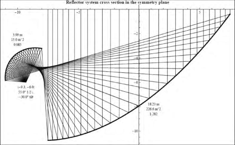
22 4 ARRAY PERFORMANCE 4.5 Optical Coupling with Reflector Offset Gregorian optics of DVA-1 telescope at DRAO Penticton, with white ray-traces from to computed with GRASP (PO, PTD, GO). Primary reflector: D=15 m projected diam Half-opening angle: 55 Feed edge taper: -16 db The antenna array will be placed at the of the subreflector. When coupled with reflector: λ/d in the λf/d in the where f: focal length 23


23 4 ARRAY PERFORMANCE 4.6 Focal Plane Beams Overlaid on antenna elements in focal plane: 3dB width of beam: FWHM (3 db circles) Spacing of beams: Nyquist spacing λ/2, Δ Signal processing power of beamformer-limited FWHM Δ 2.8 GHz 36 beams fills array. But only have 18 dual-pol available GHz Could use many more beams 120 mm 230 mm 24
 2 0.22 x 0.22 = 0.048( ) 2 1.6 x 0.8 = 1.28 ( ) 2 (7.5x) 1.6 x 1.6 = 2.56 ( ) 2 (15x) 1.0 x 0.4 = 0.4 ( ) 2 (8.3x) 1.0 x 0.8 = 0.8 ( ) 2 (16.")
24 4 ARRAY PERFORMANCE 4.7 Far-field Beams FWHM Δ 1 1 Using D=15m offset Gregorian reflector, farfield beam simulation Single beam 18 beams 36 beams 2.8 GHz 5.18 GHz 0.41 x 0.41 = 0.17( ) x 0.22 = 0.048( ) x 0.8 = 1.28 ( ) 2 (7.5x) 1.6 x 1.6 = 2.56 ( ) 2 (15x) 1.0 x 0.4 = 0.4 ( ) 2 (8.3x) 1.0 x 0.8 = 0.8 ( ) 2 (16.6x) 25
25 5 CONCLUSIONS Cryogenic (16 K) PAF for GHz designed Trx = 10 K Composite laminate radome 140 metal Vivaldi antenna elements 96 low noise (T = 3.5 K) amplifiers Post amplification, filtering FD Digital beamformer 18 beams for now Can attain ~8x FoV of SPF for 18 beams and ~16x FoV for 36 beams assuming overlap well within 3 db Airy circles. 4-element antenna prototype: Spring 2017 Future: 4-element antenna + coax + LNA: and thermal testing dewar construction Test 4-element prototype in dewar Full array construction 26
26 Thank you NRC Herzberg Astronomy and Astrophysics Lisa Locke Engineer 27


27 3 SINGLE ANTENNA ELEMENT 3.4 Manufacturing - 2 Piece Arabesque 28


28 3 SINGLE ANTENNA ELEMENT 3.4 Manufacturing 3D printing - 2 Piece Arabesque 29
Phased Array Feed Design. Stuart Hay 23 October 2009
 Phased Array Feed Design Stuart Hay 23 October 29 Outline Why phased array feeds (PAFs) for radioastronomy? General features and issues of PAF approach Connected-array PAF approach in ASKAP Why PAFs? High
Progress Towards Coherent Multibeam Arrays
 Progress Towards Coherent Multibeam Arrays Doug Henke NRC Herzberg Astronomy and Astrophysics, Victoria, Canada August 2016 ALMA Band 3 Receiver (84 116 GHz) Dual linear, 2SB Feed horn OMT (two linear
Phased Array Feeds for the SKA. WP2.2.3 PAFSKA Consortium CSIRO ASTRON DRAO NRAO BYU OdP Nancay Cornell U Manchester
 Phased Array Feeds for the SKA WP2.2.3 PAFSKA Consortium CSIRO ASTRON DRAO NRAO BYU OdP Nancay Cornell U Manchester Dish Array Hierarchy Dish Array L5 Elements PAF Dish Single Pixel Feeds L4 Sub systems
Phased Array Feeds & Primary Beams
 Phased Array Feeds & Primary Beams Aidan Hotan ASKAP Deputy Project Scientist 3 rd October 2014 CSIRO ASTRONOMY AND SPACE SCIENCE Outline Review of parabolic (dish) antennas. Focal plane response to a
NRC Herzberg Astronomy & Astrophysics
 NRC Herzberg Astronomy & Astrophysics SKA Pre-Construction Update Séverin Gaudet, Canadian Astronomy Data Centre David Loop, Director Astronomy Technology June 2016 update SKA Pre-Construction NRC Involvement
Smart Antennas in Radio Astronomy
 Smart Antennas in Radio Astronomy Wim van Cappellen cappellen@astron.nl Netherlands Institute for Radio Astronomy Our mission is to make radio-astronomical discoveries happen ASTRON is an institute for
Phased Array Feed (PAF) Design for the LOVELL Antenna based on the Octagonal Ring Antenna (ORA) Array
 Design for the LOVELL Antenna based on the Octagonal Ring Antenna (ORA) Array") Phased Array Feed (PAF) Design for the LOVELL Antenna based on the Octagonal Ring Antenna (ORA) Array M. Yang, D. Zhang, L. Danoon and A. K. Brown, School of Electrical and Electronic Engineering The University
Phased Array Feed (PAF) Design for the LOVELL Antenna based on the Octagonal Ring Antenna (ORA) Array M. Yang, D. Zhang, L. Danoon and A. K. Brown, School of Electrical and Electronic Engineering The University
Active Impedance Matched Dual-Polarization Phased Array Feed for the GBT
 Active Impedance Matched Dual-Polarization Phased Array Feed for the GBT Karl F. Warnick, David Carter, Taylor Webb, Brian D. Jeffs Department of Electrical and Computer Engineering Brigham Young University,
CHAPTER 2 MICROSTRIP REFLECTARRAY ANTENNA AND PERFORMANCE EVALUATION
 43 CHAPTER 2 MICROSTRIP REFLECTARRAY ANTENNA AND PERFORMANCE EVALUATION 2.1 INTRODUCTION This work begins with design of reflectarrays with conventional patches as unit cells for operation at Ku Band in
Phased Array Feeds A new technology for multi-beam radio astronomy
 Phased Array Feeds A new technology for multi-beam radio astronomy Aidan Hotan ASKAP Deputy Project Scientist 2 nd October 2015 CSIRO ASTRONOMY AND SPACE SCIENCE Outline Review of radio astronomy concepts.
Final Feed Selection Study For the Multi Beam Array System
 National Astronomy and Ionosphere Center Arecibo Observatory Focal Array Memo Series Final Feed Selection Study For the Multi Beam Array System By: Germán Cortés-Medellín CORNELL July/19/2002 U n i v e
Monoconical RF Antenna
 Page 1 of 8 RF and Microwave Models : Monoconical RF Antenna Monoconical RF Antenna Introduction Conical antennas are useful for many applications due to their broadband characteristics and relative simplicity.
Phased Array Feeds A new technology for wide-field radio astronomy
 Phased Array Feeds A new technology for wide-field radio astronomy Aidan Hotan ASKAP Project Scientist 29 th September 2017 CSIRO ASTRONOMY AND SPACE SCIENCE Outline Review of radio astronomy concepts
Feed Array Breadboard for Future Passive Microwave Radiometer Antennas
 Feed Array Breadboard for Future Passive Microwave Radiometer Antennas C. Cappellin 1, J. R. de Lasson 1, O. Iupikov 2, M. Ivashina 2, N. Skou 3, K. Pontoppidan 1, B. Fiorelli 4 1 TICRA, Copenhagen, Denmark,
The Future: Ultra Wide Band Feeds and Focal Plane Arrays
 The Future: Ultra Wide Band Feeds and Focal Plane Arrays Germán Cortés-Medellín NAIC Cornell University 1-1 Overview Chalmers Feed Characterization of Chalmers Feed at Arecibo Focal Plane Arrays for Arecibo
May AA Communications. Portugal
 SKA Top-level description A large radio telescope for transformational science Up to 1 million m 2 collecting area Operating from 70 MHz to 10 GHz (4m-3cm) Two or more detector technologies Connected to
Instrument Requirements and Options for Meeting the Science Opportunities MHz P. Dewdney A. Gray, B. Veidt
 Instrument Requirements and Options for Meeting the Science Opportunities 300-3000 MHz P. Dewdney A. Gray, B. Veidt Dominion Radio Astrophysical Observatory Herzberg Institute of Astrophysics National
Broadband Dual Polarized Space-Fed Antenna Arrays with High Isolation
 Progress In Electromagnetics Research C, Vol. 55, 105 113, 2014 Broadband Dual Polarized Space-Fed Antenna Arrays with High Isolation Prashant K. Mishra 1, *, Dhananjay R. Jahagirdar 1,andGirishKumar 2
Technology Drivers, SKA Pathfinders P. Dewdney
 Technology Drivers, SKA Pathfinders P. Dewdney Dominion Radio Astrophysical Observatory Herzberg Institute of Astrophysics National Research Council Canada National Research Council Canada Conseil national
Wide-Band Two-Stage GaAs LNA for Radio Astronomy
 Progress In Electromagnetics Research C, Vol. 56, 119 124, 215 Wide-Band Two-Stage GaAs LNA for Radio Astronomy Jim Kulyk 1,GeWu 2, Leonid Belostotski 2, *, and James W. Haslett 2 Abstract This paper presents
Mathematical Model for Progressive Phase Distribution of Ku-band Reflectarray Antennas
 Mathematical Model for Progressive Phase Distribution of Ku-band Reflectarray Antennas M. Y. Ismail, M. Inam, A.. M. Zain, N. Misran Abstract Progressive phase distribution is an important consideration
Characteristics of Smooth-Walled Spline-Profile Horns for Tightly Packed Feed-Array of RATAN-600 Radio Telescope
 Characteristics of Smooth-Walled Spline-Profile Horns for Tightly Packed Feed-Array of RATAN-600 Radio Telescope N. POPENKO 1, R. CHERNOBROVKIN 1, I. IVANCHENKO 1, C. GRANET 3, V. KHAIKIN 2 1 Usikov Institute
A NOVEL DUAL-BAND PATCH ANTENNA FOR WLAN COMMUNICATION. E. Wang Information Engineering College of NCUT China
 Progress In Electromagnetics Research C, Vol. 6, 93 102, 2009 A NOVEL DUAL-BAND PATCH ANTENNA FOR WLAN COMMUNICATION E. Wang Information Engineering College of NCUT China J. Zheng Beijing Electro-mechanical
Circular Focal Plane Array for Astronomic Applications
 International Workshop on Phased Array Antenna Systems for Radio Astronomy Circular Focal Plane Array for Astronomic Applications Rémi Sarkis, Christophe Craeye May 3-5, 21 Provo, Utah, USA 1 Introduction
Etude d un récepteur SIS hétérodyne multi-pixels double polarisation à 3mm de longueur d onde pour le télescope de Pico Veleta
 Etude d un récepteur SIS hétérodyne multi-pixels double polarisation à 3mm de longueur d onde pour le télescope de Pico Veleta Study of a dual polarization SIS heterodyne receiver array for the 3mm band
School of Electrical Engineering. EI2400 Applied Antenna Theory Lecture 8: Reflector antennas
 School of Electrical Engineering EI2400 Applied Antenna Theory Lecture 8: Reflector antennas Reflector antennas Reflectors are widely used in communications, radar and radio astronomy. The largest reflector
Design of a Novel Compact Cup Feed for Parabolic Reflector Antennas
 Progress In Electromagnetics Research Letters, Vol. 64, 81 86, 2016 Design of a Novel Compact Cup Feed for Parabolic Reflector Antennas Amir Moallemizadeh 1,R.Saraf-Shirazi 2, and Mohammad Bod 2, * Abstract
KULLIYYAH OF ENGINEERING
 KULLIYYAH OF ENGINEERING DEPARTMENT OF ELECTRICAL & COMPUTER ENGINEERING ANTENNA AND WAVE PROPAGATION LABORATORY (ECE 4103) EXPERIMENT NO 3 RADIATION PATTERN AND GAIN CHARACTERISTICS OF THE DISH (PARABOLIC)
Towards SKA Multi-beam concepts and technology
 Towards SKA Multi-beam concepts and technology SKA meeting Meudon Observatory, 16 June 2009 Philippe Picard Station de Radioastronomie de Nançay philippe.picard@obs-nancay.fr 1 Square Kilometre Array:
A 30 GHz PLANAR ARRAY ANTENNA USING DIPOLE- COUPLED-LENS. Campus UAB, Bellaterra 08193, Barcelona, Spain
 Progress In Electromagnetics Research Letters, Vol. 25, 31 36, 2011 A 30 GHz PLANAR ARRAY ANTENNA USING DIPOLE- COUPLED-LENS A. Colin 1, *, D. Ortiz 2, E. Villa 3, E. Artal 3, and E. Martínez- González
Differential and Single Ended Elliptical Antennas for GHz Ultra Wideband Communication
 Differential and Single Ended Elliptical Antennas for 3.1-1.6 GHz Ultra Wideband Communication Johnna Powell Anantha Chandrakasan Massachusetts Institute of Technology Microsystems Technology Laboratory
Design of Low-Index Metamaterial Lens Used for Wideband Circular Polarization Antenna
 Progress In Electromagnetics Research Letters, Vol. 68, 93 98, 2017 Design of Low-Index Metamaterial Lens Used for Wideband Circular Polarization Antenna Yong Wang and Yanlin Zou * Abstract A novel low-index
- reduce cross-polarization levels produced by reflector feeds - produce nearly identical E- and H-plane patterns of feeds
 Corrugated Horns Motivation: Contents - reduce cross-polarization levels produced by reflector feeds - produce nearly identical E- and H-plane patterns of feeds 1. General horn antenna applications 2.
Chapter 2. Modified Rectangular Patch Antenna with Truncated Corners. 2.1 Introduction of rectangular microstrip antenna
 Chapter 2 Modified Rectangular Patch Antenna with Truncated Corners 2.1 Introduction of rectangular microstrip antenna 2.2 Design and analysis of rectangular microstrip patch antenna 2.3 Design of modified
ALMA Band 1. Charles Cunningham and Stéphane Claude. IRMMW-THZ 2005, Williamsburg. IRMMW-THZ 2005, Williamsburg
 ALMA Band 1 Charles Cunningham and Stéphane Claude Canadian Users - ALMA Canadian LRP 2010 The Atacama Large Millimetre Array is the top priority in LRP2000 The Atacama Large Millimetre Array (ALMA) is
A Broadband Omnidirectional Antenna Array for Base Station
 Progress In Electromagnetics Research C, Vol. 54, 95 101, 2014 A Broadband Omnidirectional Antenna Array for Base Station Bo Wang 1, *, Fushun Zhang 1,LiJiang 1, Qichang Li 2, and Jian Ren 1 Abstract A
PLANAR BEAM-FORMING ARRAY FOR BROADBAND COMMUNICATION IN THE 60 GHZ BAND
 PLANAR BEAM-FORMING ARRAY FOR BROADBAND COMMUNICATION IN THE 6 GHZ BAND J.A.G. Akkermans and M.H.A.J. Herben Radiocommunications group, Eindhoven University of Technology, Eindhoven, The Netherlands, e-mail:
SKA technology: RF systems & signal processing. Mike Jones University of Oxford
 SKA technology: RF systems & signal processing Mike Jones University of Oxford SKA RF processing Dish receivers Cryogenics RF electronics Fast sampling Antenna processing AA receivers RF gain chain Sampling/antenna
March Phased Array Technology. Andrew Faulkner
 Aperture Arrays Michael Kramer Sparse Type of AA selection 1000 Sparse AA-low Sky Brightness Temperature (K) 100 10 T sky A eff Fully sampled AA-mid Becoming sparse Aeff / T sys (m 2 / K) Dense A eff /T
Efficient Metasurface Rectenna for Electromagnetic Wireless Power Transfer and Energy Harvesting
 Progress In Electromagnetics Research, Vol. 161, 35 40, 2018 Efficient Metasurface Rectenna for Electromagnetic Wireless Power Transfer and Energy Harvesting Mohamed El Badawe and Omar M. Ramahi * Abstract
Detector Systems. Graeme Carrad
 Detector Systems Graeme Carrad November 2011 The Basic Structure of a typical Radio Telescope Antenna Receiver Conversion Digitiser Signal Processing / Correlator They are much the same CSIRO. Radiotelescope
Reflectarray Antennas
 Reflectarray Antennas International Journal of Computer Applications (0975 8887) Kshitij Lele P.G. Student, Department of EXTC DJ Sanghvi College of Engineering Ami A. Desai P.G. Student Department of
Electrically Reconfigurable Radiation Patterns of Slot Antenna Array Using Agile Plasma Wall
 Progress In Electromagnetics Research C, Vol. 73, 75 80, 2017 Electrically Reconfigurable Radiation Patterns of Slot Antenna Array Using Agile Plasma Wall Oumar A. Barro *, Mohammed Himdi, and Alexis Martin
BROADBAND AND HIGH-GAIN PLANAR VIVALDI AN- TENNAS BASED ON INHOMOGENEOUS ANISOTROPIC ZERO-INDEX METAMATERIALS
 Progress In Electromagnetics Research, Vol. 120, 235 247, 2011 BROADBAND AND HIGH-GAIN PLANAR VIVALDI AN- TENNAS BASED ON INHOMOGENEOUS ANISOTROPIC ZERO-INDEX METAMATERIALS B. Zhou, H. Li, X. Y. Zou, and
CHAPTER 5 THEORY AND TYPES OF ANTENNAS. 5.1 Introduction
 CHAPTER 5 THEORY AND TYPES OF ANTENNAS 5.1 Introduction Antenna is an integral part of wireless communication systems, considered as an interface between transmission line and free space [16]. Antenna
THE KAROO ARRAY TELESCOPE (KAT) & FPA EFFORT IN SOUTH AFRICA
 & FPA EFFORT IN SOUTH AFRICA") THE KAROO ARRAY TELESCOPE (KAT) & FPA EFFORT IN SOUTH AFRICA Dr. Dirk Baker (KAT FPA Sub-system Manager) Prof. Justin Jonas (SKA SA Project Scientist) Ms. Anita Loots (KAT Project Manager) Mr. David de
THE KAROO ARRAY TELESCOPE (KAT) & FPA EFFORT IN SOUTH AFRICA Dr. Dirk Baker (KAT FPA Sub-system Manager) Prof. Justin Jonas (SKA SA Project Scientist) Ms. Anita Loots (KAT Project Manager) Mr. David de
INSTITUTE OF AERONAUTICAL ENGINEERING Dundigal, Hyderabad ELECTRONICS AND COMMUNIACTION ENGINEERING QUESTION BANK
 INSTITUTE OF AERONAUTICAL ENGINEERING Dundigal, Hyderabad - 500 04 ELECTRONICS AND COMMUNIACTION ENGINEERING QUESTION BANK Course Name : Antennas and Wave Propagation (AWP) Course Code : A50418 Class :
Integrated receivers for mid-band SKA. Suzy Jackson Engineer, Australia Telescope National Facility
 Integrated receivers for mid-band SKA Suzy Jackson Engineer, Australia Telescope National Facility ASKAP/SKA Special Technical Brief 23 rd October, 2009 Talk overview Mid band SKA receiver challenges ASKAP
Multi-octave radio frequency systems: Developments of antenna technology in radio astronomy and imaging systems
 Multi-octave radio frequency systems: Developments of antenna technology in radio astronomy and imaging systems Professor Tony Brown School of Electrical and Electronic Engineering University of Manchester
MAGNETO-DIELECTRIC COMPOSITES WITH FREQUENCY SELECTIVE SURFACE LAYERS
 MAGNETO-DIELECTRIC COMPOSITES WITH FREQUENCY SELECTIVE SURFACE LAYERS M. Hawley 1, S. Farhat 1, B. Shanker 2, L. Kempel 2 1 Dept. of Chemical Engineering and Materials Science, Michigan State University;
A Compact Dual-Polarized Antenna for Base Station Application
 Progress In Electromagnetics Research Letters, Vol. 59, 7 13, 2016 A Compact Dual-Polarized Antenna for Base Station Application Guan-Feng Cui 1, *, Shi-Gang Zhou 2,Shu-XiGong 1, and Ying Liu 1 Abstract
Chalmers Publication Library
 Chalmers Publication Library Analysis of the strut and feed blockage effects in radio telescopes with compact UWB feeds This document has been downloaded from Chalmers Publication Library (CPL). It is
Practical Antennas and. Tuesday, March 4, 14
 Practical Antennas and Transmission Lines Goals Antennas are the interface between guided waves (from a cable) and unguided waves (in space). To understand the various properties of antennas, so as to
S-parameters. Jvdtang. RFTE course, #3: RF specifications and system design (I) 73
 73") S-parameters RFTE course, #3: RF specifications and system design (I) 73 S-parameters (II) Linear networks, or nonlinear networks operating with signals sufficiently small to cause the networks to respond
S-parameters RFTE course, #3: RF specifications and system design (I) 73 S-parameters (II) Linear networks, or nonlinear networks operating with signals sufficiently small to cause the networks to respond
Compact MIMO Antenna with Cross Polarized Configuration
 Proceedings of the 4th WSEAS Int. Conference on Electromagnetics, Wireless and Optical Communications, Venice, Italy, November 2-22, 26 11 Compact MIMO Antenna with Cross Polarized Configuration Wannipa
Radiation Performance of an Elliptical Patch Antenna with Three Orthogonal Sector Slots
 ROMANIAN JOURNAL OF INFORMATION SCIENCE AND TECHNOLOGY Volume 14, Number 2, 2011, 123 130 Radiation Performance of an Elliptical Patch Antenna with Three Orthogonal Sector Slots Vijay SHARMA 1, V. K. SAXENA
L-Band and X-Band Antenna Design and Development for NeXtRAD
 L-Band and X-Band Antenna Design and Development for NeXtRAD S. T. Paine, P. Cheng, D. W. O Hagan, M. R. Inggs, H. D. Griffiths* Department of Electrical Engineering Radar Remote Sensing Group University
Aperture Antennas. Reflectors, horns. High Gain Nearly real input impedance. Huygens Principle
 Antennas 97 Aperture Antennas Reflectors, horns. High Gain Nearly real input impedance Huygens Principle Each point of a wave front is a secondary source of spherical waves. 97 Antennas 98 Equivalence
Printed MSA fed High Gain Wide band Antenna using Fabry Perot Cavity Resonator
 Printed MSA fed High Gain Wide band Antenna using Fabry Perot Cavity Resonator Sonal A. Patil R. K. Gupta L. K. Ragha ABSTRACT A low cost, printed high gain and wideband antenna using Fabry Perot cavity
Antenna-coupled bolometer arrays for measurement of the Cosmic Microwave Background polarization
 Journal of Low Temperature Physics manuscript No. (will be inserted by the editor) M. J. Myers a K. Arnold a P. Ade b G. Engargiola c W. Holzapfel a A. T. Lee a X. Meng d R. O Brient a P. L. Richards a
A K-Band Flat Transmitarray Antenna with a Planar Microstrip Slot-Fed Patch Antenna Feeder
 Progress In Electromagnetics Research C, Vol. 64, 97 104, 2016 A K-Band Flat Transmitarray Antenna with a Planar Microstrip Slot-Fed Patch Antenna Feeder Lv-Wei Chen and Yuehe Ge * Abstract A thin phase-correcting
Antenna Design: Simulation and Methods
 Antenna Design: Simulation and Methods Radiation Group Signals, Systems and Radiocommunications Department Universidad Politécnica de Madrid Álvaro Noval Sánchez de Toca e-mail: anoval@gr.ssr.upm.es Javier
Proximity fed Gap Coupled Array Antenna with DGS Backed with Periodic Metallic Strips
 Proximity fed Gap Coupled Array Antenna with DGS Backed with Periodic Metallic Strips Jacob Abraham 1 and Thomaskutty Mathew Department of Electronics, School of Technology and Applied Sciences, Mahatma
High Gain Ultra-Wideband Parabolic Reflector Antenna Design Using Printed LPDA Antenna Feed
 American Scientific Research Journal for Engineering, Technology, and Sciences (ASRJETS) ISSN (Print) 2313-441, ISSN (Online) 2313-442 Global Society of Scientific Research and Researchers http://asrjetsjournal.org/
The Shaped Coverage Area Antenna for Indoor WLAN Access Points
 The Shaped Coverage Area Antenna for Indoor WLAN Access Points A.BUMRUNGSUK and P. KRACHODNOK School of Telecommunication Engineering, Institute of Engineering Suranaree University of Technology 111 University
A Dual-Polarized MIMO Antenna with EBG for 5.8 GHz WLAN Application
 Progress In Electromagnetics Research Letters, Vol. 51, 15 2, 215 A Dual-Polarized MIMO Antenna with EBG for 5.8 GHz WLAN Application Xiaoyan Zhang 1, 2, *, Xinxing Zhong 1,BinchengLi 3, and Yiqiang Yu
Design and Matching of a 60-GHz Printed Antenna
 Application Example Design and Matching of a 60-GHz Printed Antenna Using NI AWR Software and AWR Connected for Optenni Figure 1: Patch antenna performance. Impedance matching of high-frequency components
Performance Analysis of a Patch Antenna Array Feed For A Satellite C-Band Dish Antenna
 Cyber Journals: Multidisciplinary Journals in Science and Technology, Journal of Selected Areas in Telecommunications (JSAT), November Edition, 2011 Performance Analysis of a Patch Antenna Array Feed For
Circularly Polarized Microstrip Patch Antenna with T-Shaped Slot
 IJECT Vo l. 4, Is s u e Sp l - 4, Ap r i l - Ju n e 2013 ISSN : 2230-7109 (Online) ISSN : 2230-9543 (Print) Circularly Polarized Microstrip Patch Antenna with T-Shaped Slot 1 Sanyog Rawat, 2 K K Sharma
L-BAND COPLANAR SLOT LOOP ANTENNA FOR INET APPLICATIONS
 L-BAND COPLANAR SLOT LOOP ANTENNA FOR INET APPLICATIONS Jeyasingh Nithianandam Electrical and Computer Engineering Department Morgan State University, 500 Perring Parkway, Baltimore, Maryland 5 ABSTRACT
Antenna Fundamentals. Microwave Engineering EE 172. Dr. Ray Kwok
 Antenna Fundamentals Microwave Engineering EE 172 Dr. Ray Kwok Reference Antenna Theory and Design Warran Stutzman, Gary Thiele, Wiley & Sons (1981) Microstrip Antennas Bahl & Bhartia, Artech House (1980)
TOPIC 2 WAVEGUIDE AND COMPONENTS
 TOPIC 2 WAVEGUIDE AND COMPONENTS COURSE LEARNING OUTCOME (CLO) CLO1 Explain clearly the generation of microwave, the effects of microwave radiation and the propagation of electromagnetic in a waveguide
MICROWAVE MICROWAVE TRAINING BENCH COMPONENT SPECIFICATIONS:
 Microwave section consists of Basic Microwave Training Bench, Advance Microwave Training Bench and Microwave Communication Training System. Microwave Training System is used to study all the concepts of
Design and Development of a 2 1 Array of Slotted Microstrip Line Fed Shorted Patch Antenna for DCS Mobile Communication System
 Wireless Engineering and Technology, 2013, 4, 59-63 http://dx.doi.org/10.4236/wet.2013.41009 Published Online January 2013 (http://www.scirp.org/journal/wet) 59 Design and Development of a 2 1 Array of
A 3 20GHz Vivaldi Antenna with Modified Edge
 A 3 20GHz Vivaldi Antenna with Modified Edge Bieng-Chearl Ahn* * and Otgonbaatar Gombo Applied Electromagnetics Laboratory, Department of Radio and Communications Engineering Chungbuk National University,
Effect of Open Stub Slots for Enhancing the Bandwidth of Rectangular Microstrip Antenna
 International Journal of Electronics Engineering, 3 (2), 2011, pp. 221 226 Serials Publications, ISSN : 0973-7383 Effect of Open Stub Slots for Enhancing the Bandwidth of Rectangular Microstrip Antenna
Microwave and optical systems Introduction p. 1 Characteristics of waves p. 1 The electromagnetic spectrum p. 3 History and uses of microwaves and
 Microwave and optical systems Introduction p. 1 Characteristics of waves p. 1 The electromagnetic spectrum p. 3 History and uses of microwaves and optics p. 4 Communication systems p. 6 Radar systems p.
Design and Development of Rectangular Microstrip Array Antennas for X and Ku Band Operation
 International Journal of Electronics Engineering, 2 (2), 2010, pp. 265 270 Design and Development of Rectangular Microstrip Array Antennas for X and Ku Band Operation B. Suryakanth, NM Sameena, and SN
DESIGN OF OMNIDIRECTIONAL HIGH-GAIN AN- TENNA WITH BROADBAND RADIANT LOAD IN C WAVE BAND
 Progress In Electromagnetics Research C, Vol. 33, 243 258, 212 DESIGN OF OMNIDIRECTIONAL HIGH-GAIN AN- TENNA WITH BROADBAND RADIANT LOAD IN C WAVE BAND S. Lin *, M.-Q. Liu, X. Liu, Y.-C. Lin, Y. Tian,
Design, Development and Testing of RF Window for C band 250 kw CW Power Klystron
 Available online www.ejaet.com European Journal of Advances in Engineering and Technology, 2016, 3(6): 26-30 Research Article ISSN: 2394-658X Design, Development and Testing of RF Window for C band 250
Double Negative Left-Handed Metamaterials for Miniaturization of Rectangular Microstrip Antenna
 J. Electromagnetic Analysis & Applications, 2010, 2, 347-351 doi:10.4236/jemaa.2010.26044 Published Online June 2010 (http://www.scirp.org/journal/jemaa) 347 Double Negative Left-Handed Metamaterials for
Chapter 7 Design of the UWB Fractal Antenna
 Chapter 7 Design of the UWB Fractal Antenna 7.1 Introduction F ractal antennas are recognized as a good option to obtain miniaturization and multiband characteristics. These characteristics are achieved
7. Liquid Crystal and Liquid Crystal Polymer based Antennas
 Chapter 7 7. Liquid Crystal and Liquid Crystal Polymer based Antennas 7.1 Introduction: Depending on the temperature, liquid crystal (LC) phase exists in between crystalline solid and an isotropic liquid.
Compact Vivaldi Antenna With Balun Feed For Uwb
 IOSR Journal of Electronics and Communication Engineering (IOSR-JECE) e-issn: 2278-2834,p-ISSN: 2278-8735 PP 80-84 www.iosrjournals.org Compact Vivaldi Antenna With Balun Feed For Uwb Shijina S. 1,Sareena
TRANSMITTING ANTENNA WITH DUAL CIRCULAR POLARISATION FOR INDOOR ANTENNA MEASUREMENT RANGE
 TRANSMITTING ANTENNA WITH DUAL CIRCULAR POLARISATION FOR INDOOR ANTENNA MEASUREMENT RANGE Michal Mrnka, Jan Vélim Doctoral Degree Programme (2), FEEC BUT E-mail: xmrnka01@stud.feec.vutbr.cz, velim@phd.feec.vutbr.cz
Newsletter 5.4. New Antennas. The profiled horns. Antenna Magus Version 5.4 released! May 2015
 Newsletter 5.4 May 215 Antenna Magus Version 5.4 released! Version 5.4 sees the release of eleven new antennas (taking the total number of antennas to 277) as well as a number of new features, improvements
NATIONAL RADIO ASTRONOMY OBSERVATORY Socorro, NM ELECTRONICS DIVISION TECHNICAL NOTE NO. 217
 NATIONAL RADIO ASTRONOMY OBSERVATORY Socorro, NM ELECTRONICS DIVISION TECHNICAL NOTE NO. 217 Preliminary Measured Results of a Diagonal Quadruple-Ridged Ku-Band OMT Gordon Courts November 29,2010 Preliminary
Antenna and Analog Beamformer
 Antenna and Analog Beamformer Requirements The antenna system is responsible for collecting radiation from the sky and presenting a suitably conditioned 80-300 MHz RF signal to the receiver node. Because
Accurate simulation and experimental validation of a 4-by-4 antenna array for Ka band
 Accurate simulation and experimental validation of a 4-by-4 antenna array for Ka band CST EUC 2016 - Strasbourg B. Lesur, M. Thévenot, T. Monédière, C. Mellé Outline Introduction Context Objectives Design
Practical Aspects of Focal Plane Array Testing
 Practical Aspects of Focal Plane Array Testing Lessons from an FPA Test-bed at CSIRO, Marsfield Douglas B. Hayman1-3, Trevor S. Bird2,3, Karu P. Esselle3 and Peter J. Hall4 1 2 3 CSIRO Astronomy and Space
A Compact Dual-Band Dual-Polarized Antenna for Base Station Application
 Progress In Electromagnetics Research C, Vol. 64, 61 70, 2016 A Compact Dual-Band Dual-Polarized Antenna for Base Station Application Guanfeng Cui 1, *, Shi-Gang Zhou 2,GangZhao 1, and Shu-Xi Gong 1 Abstract
HIGH GAIN AND LOW COST ELECTROMAGNETICALLY COUPLED RECTAGULAR PATCH ANTENNA
 HIGH GAIN AND LOW COST ELECTROMAGNETICALLY COUPLED RECTAGULAR PATCH ANTENNA Raja Namdeo, Sunil Kumar Singh Abstract: This paper present high gain and wideband electromagnetically coupled patch antenna.
A NEW INNOVATIVE ANTENNA CONCEPT FOR BOTH NARROW BAND AND UWB APPLICATIONS. Neuroscience, CIN, University of Tuebingen, Tuebingen, Germany
 Progress In Electromagnetics Research, Vol. 139, 121 131, 213 A NEW INNOVATIVE ANTENNA CONCEPT FOR BOTH NARROW BAND AND UWB APPLICATIONS Irena Zivkovic 1, * and Klaus Scheffler 1, 2 1 Max Planck Institute
An Introduction to Antennas
 May 11, 010 An Introduction to Antennas 1 Outline Antenna definition Main parameters of an antenna Types of antennas Antenna radiation (oynting vector) Radiation pattern Far-field distance, directivity,
STATISTICAL DISTRIBUTION OF INCIDENT WAVES TO MOBILE ANTENNA IN MICROCELLULAR ENVIRONMENT AT 2.15 GHz
 EUROPEAN COOPERATION IN COST259 TD(99) 45 THE FIELD OF SCIENTIFIC AND Wien, April 22 23, 1999 TECHNICAL RESEARCH EURO-COST STATISTICAL DISTRIBUTION OF INCIDENT WAVES TO MOBILE ANTENNA IN MICROCELLULAR
Design of a UHF Pyramidal Horn Antenna Using CST
 Volume 114 No. 7 2017, 447-457 ISSN: 1311-8080 (printed version); ISSN: 1314-3395 (on-line version) url: http://www.ijpam.eu ijpam.eu Design of a UHF Pyramidal Horn Antenna Using CST Biswa Ranjan Barik
Rectangular Patch Antenna to Operate in Flame Retardant 4 Using Coaxial Feeding Technique
 International Journal of Electronics Engineering Research. ISSN 0975-6450 Volume 9, Number 3 (2017) pp. 399-407 Research India Publications http://www.ripublication.com Rectangular Patch Antenna to Operate
CHAPTER 3 METHODOLOGY AND SOFTWARE TOOLS
 CHAPTER 3 METHODOLOGY AND SOFTWARE TOOLS Microstrip Patch Antenna Design In this chapter, the procedure for designing of a rectangular microstrip patch antenna is described. The proposed broadband rectangular
Merging Propagation Physics, Theory and Hardware in Wireless. Ada Poon
 HKUST January 3, 2007 Merging Propagation Physics, Theory and Hardware in Wireless Ada Poon University of Illinois at Urbana-Champaign Outline Multiple-antenna (MIMO) channels Human body wireless channels
A LABORATORY COURSE ON ANTENNA MEASUREMENT
 A LABORATORY COURSE ON ANTENNA MEASUREMENT Samuel Parker Raytheon Systems Company, 2000 East Imperial Highway RE/R02/V509, El Segundo, CA 90245 Dean Arakaki Electrical Engineering Department, California