Passive Components. DC GHz
|
|
|
- Caroline Kelly
- 5 years ago
- Views:
Transcription
1 Passive Components DC GHz
2 Spectrum Elektrotechnik GmbH is a leading manufacturer of RF and Microwave Components in the Frequency Range of DC to 50.0 GHz. The products are published in eight individual catalogs, showing detailed information and comprehensive data. Adapters, DC - 50 GHz, 50 Ohms Coaxial Adapters (In Series and Between Series) High Power Adapters Push-On Adapters Waveguide to Coax Adapters Microwave Connectors, DC - 50 GHz, 50 Ohms Blind Mate Connectors Coaxial Connectors High Power Connectors Multi Pin Connectors Push-On Connectors Cable Assemblies, DC - 50 GHz, 50 Ohms ANA Test Cables Flexible Cable Assemblies Low Loss Cable Assemblies Phase Stable Cable Assemblies Semi Rigid Cable Assemblies (Dia. 0.34" to 1") Test Necessities and Accessories, DC - 50 GHz, 50 Ohms LRL, TRL Calibration and Verification Kits ANA Cable Assemblies Torque Wrenches Interface Gauges Calibration Kits Terminations Components, DC - 50 GHz, 50 Ohms Coaxial Switches Coaxial Terminations DC - Block Connectors Gain Amplitude Equalizers Hybrid Housings Phase Adjusters Precision Coaxial Terminations Precision Waveguide Terminations Special Products and Services: Adapter Sets, Antennas, Blind Mate Connectors, Calibration Kits, Custom Connectors/Adapters, Delay Lines, Detectors, Directional Couplers, Impedance Transformers, Interface Gauges, Isolators & Circulators, Lightning Surge Suppressors, Limiters, Phase Stable Assemblies, Precision Mismatches, Push-Ons, RF-Multipin Connectors SQ-8, Rotary Joints, Supercomponents, Torque Wrenches. Quick Connections, 50 Ohms Blind Mate Connectors Push - On Adapters Push - On Connectors Push - On Cable Assemblies Components, 75 Ohms Adapters Attenuators Connectors Switches Transformers Machines and Tools Coax Cable Cutting/Stripping Machines Flex Cable Cutting/Stripping Machines Semi-Rigid Cable Bending Machines Spectrum Elektrotechnik GmbH P.O. Box , Munich, Germany Tel. (89) E - Mail: CompuServe.com Fax (89) (Country Code: 49)
3 1compo1.pm6 This Handbook shows a most extensive line of Passive Components in the frequency range of DC to 50.0 GHz. On pages 6 and 7 you will find a Quick Reference Guide by Sections, lining out the eleven sections covered in this Handbook, referencing in detail the content of the individual chapters. Sections I through VIII comprise products, Spectrum Elektrotechnik GmbH offers as standard. In most of those product categories the Company is a leading supplier and offers a large variety of state-of-the-art components. Section IX however, Special Products & Services, covers products the Company usually designs and manufactures to customer specifications. This section also contains some products that are standard, but covered already in other Spectrum Catalogs. As they are somehow components, or related to components, it seemed to be appropriate to at least mention them in the ninth section of the Component Handbook. But just in case you still do not find exactly the product you require, please contact the factory or your nearest Spectrum Area Representative. Due to continuous development we may have solved a similar problem for someone else, or did develop already the product you require. As it is our main goal to improve specification and performance of the products, Spectrum Elektrotechnik GmbH has to reserve the right to change specifications, design and any other information shown in this Handbook at any time without previous notice. Contents Company Profile... Ordering Information... Quick Reference Guide by Sections... Section I: Phase Adjusters Introduction... Selection Chart: Phase Adjusters... Phase Adjustable Connectors... Section II: Precision Coaxial Terminations Introduction... Selection Chart: Coaxial Terminations... Selection Chart: Short/Open Circuit Coax. Terminations... Terminations... Section III: Precision Waveguide Terminations Introduction... Outline Drawing and Technical Data... Section IV: Coaxial Attenuators Introduction... Outline Drawings and Technical Data... Section V: Hybrid Housings Outline Drawings and Technical Data... Section VI: Gain Amplitude Equalizers Fundamentals... Standard Gain Amplitude Equalizers... Equalizer Outline Drawings... Section VII: DC - Block Connectors Introduction... Outline Drawings and Technical Data... Section VIII: Coaxial Switches Introduction... Ordering Information... SPDT Switches... Multi - Through Switches... Transfer Switches... Section IX: Special Products & Services Adapter Sets... Antennas... Blind Mate Connectors... Calibration Kits... Custom Connectors/Adapters... Delay Lines... Detectors... Directional Couplers... Impedance Transformers... Interface Gauges... Isolators & Circulators... Lightning Surge Suppressors... Limiters... Phase Stable Assemblies... Precision Mismatches... PUSH - ONs... RF - Multipin Connector SQ-8... Rotary Joints... Supercomponents... Torque Wrenches... Section X: Connector Specifications Connector Specifications... Interface Mating Dimensions... Connector Specifications Summary... Section XI: Glossary... Part Number Index... Index... Because of the comprehensive information gathered in this volume, we call it a Handbook, hopefully the Handbook you like to work with best. If you find the 151 time, we would appreciate your personal opinion about this Handbook. Sales Representatives Spectrum Elektrotechnik GmbH P.O. Box , Munich, Germany Tel. (89) , Fax (89) (Country Code: 49) 3 Page
4 The Company 4 Spectrum Elektrotechnik GmbH was founded in 1981 and has become a leading supplier of state-of-the-art components used in the RF and Microwave Technology, such as Connectors, Adapters, Cable Assemblies, Phase Shifters, Couplers, Gain Amplitude Equalizers, Terminations, Calibration Kits, etc., etc. In addition, a number of complex and integrated components have been engineered and manufactured for certain programs and to the customers' needs. Throughout the world, Spectrum Elektrotechnik GmbH has established a reputation as a design, development and manufacturing center. The Company has been recognized as setting standards, introducing new ideas and leading into new technologies. The Products The products are used in commercial systems such as Cellular Applications, Radios, SatCom/VSAT, Satellites and Space Applications, Test Centers and Wireless Communication: The products are used in defence applications such as Airborne Radars, Electronic Intelligence, Electronic Warfare, Jamming Systems, Missile Guidance, etc. Whenever RF or Microwave Expertise and Advanced Manufacturing Technologies are needed you will find Spectrum Elektrotechnik GmbH. Capabilities and Facilities The departments within the Company have been set up as an intelligent Network, guaranteeing complete inhouse control of every operation and procedure, from design, development, manufacturing, assembly and testing. Spectrum Elektrotechnik GmbH is small enough to react quickly and large enough to handle extensive orders of important programs successfully. This capability enables us to develop, manufacture and test the extensive range of Products meeting the highest standards of quality and performance. Spectrum Elektrotechnik GmbH introduced CAD design centers already in 1984 as well as CAD/CAM work stations to provide data to computer controlled machines. The Company operates the most advanced machines and uses Test Centers to 50.0 GHz from HP and to 40.0 GHz from Wiltron. Manufacturing and Quality Control comply with DIN - ISO 9000, permitting to meet strict requirements in Commercial, Avionics, Military and Hi-Rel applications. A Final Inspection to 100% is standard, Tests on electrical and physical performance, their tolerances, the workmanship, and the compliance to applicable specifications. Support An adequate and knowledgeable staff is always available to support the Customers in respect to Applications, Engineering and Sales. The staff acts as a Team, understanding applications, specifications, needs, priorities and problems as well. A net of distributors assures immediate delivery of off-the-shelf products. Authorized technical knowledgeable Representatives will provide immediate assistance to the customer's needs. Spectrum Elektrotechnik GmbH P.O. Box , Munich, Germany Tel. (89) , Fax (89) (Country Code: 49) 1compo1.pm6
5 Ordering Information Ordering Please include both, Spectrum Elektrotechnik GmbH part number, and a description of the item(s) ordered. If special features are required, describe them as completely as possible and include an engineering sketch. Orders may be placed directly with the factory in Munich or with any authorized Spectrum Elektrotechnik GmbH Representative. Minimum Factory Order is DM Acceptance of Orders All orders are subject to acceptance at the discretion of the factory and with an Order Acknowledgment from Spectrum Elektrotechnik GmbH. Terms Upon approval of credit, payment is due Net 30 days from date of invoice. Late payments are subject to a 1.5 % monthly charge on past due balances. Shipments Spectrum Elektrotechnik GmbH ships via the most expedient reliable carrier. Shipment F.O.B., Spectrum Elektrotechnik GmbH plant, will be sent freight prepaid and billed unless other prior arrangements are made. Spectrum Elektrotechnik GmbH will use any acceptable method of delivery specifically requested by the customer. Damaged Materials/Shortages All orders should be inspected upon receipt for both completeness and to insure receipt of materials in proper condition. All claims for shortages must be made within thirty (30) days after date of shipment of material from Spectrum Elektrotechnik GmbH plant. Title to goods passes to the Buyer upon delivery to the carrier and risk of loss or damage shall thereafter rest with the Buyer. Claims for damage or loss while material is in transit must be made against the carrier by the Buyer. Cancellation Cancellation of, or changes to an order acknowledged by Spectrum Elektrotechnik GmbH are accepted only upon terms that protect Spectrum Elektrotechnik GmbH against loss. Returns Excess or unused material cannot be returned for credit without factory authorization. Such material is subject to a handling charge of not less than 15 % upon return and inspection of material at the factory. In no case will Spectrum Elektrotechnik GmbH authorize return of material beyond ninety (90) days after shipment from the factory. Credit for returned material is issued by Spectrum Elektrotechnik GmbH only to the original purchaser. Freight charges for returned material is the responsibility of the Buyer. Defective Material Claims for defective material or workmanship are subject to verification by Spectrum Elektrotechnik GmbH Quality Control, and must have prior factory authorization. Upon verification, Spectrum Elektrotechnik GmbH reserves the right to repair or replace, as deemed necessary. Prices / Specifications Unless otherwise specified, prices quoted are F. O. B. Spectrum Elektrotechnik GmbH plant. Both prices and specifications are subject to modification without prior notice. Patent and Trademark Indemnity Buyer agrees at Buyer's expense to protect and defend Seller against any and all claims of patent or trademark infringement arising from Seller' s compliance with Buyer's designs or specifications or instruction and to hold Seller harmless from all losses, damages, costs and expenses attributable to any such claim or claims. Seller shall have the right to approve or disapprove counsel designated by Buyer to defend such claims. 1compo1.pm6 Warranty Spectrum Elektrotechnik GmbH warrants products of its manufacture to be free from defects in material and workmanship under conditions of normal use. If, within one year after delivery of the original owner and after prepaid return by the original owner, any Spectrum Elektrotechnik GmbH product is found to be defective, Spectrum Elektrotechnik GmbH shall, at its option, repair or replace said defective item. This warranty does not apply to products which have been disassembled, modified or subjected to conditions exceeding the applicable specifications or ratings. Spectrum Elektrotechnik GmbH reserves the right to make design changes without notice on any of its products and without any obligation to make same or similar changes to items previously purchased. In no event does Spectrum Elektrotechnik GmbH assume liability for installation labor or for consequential damages. This warranty is the extent of the obligation or liability assumed by Spectrum Elektrotechnik GmbH with respect to its products, and no other warranty or guarantee is either expressed or implied. Spectrum Elektrotechnik GmbH P.O. Box , Munich, Germany Tel. (89) , Fax (89) (Country Code: 49) 5
6 Quick Reference Guide by Sections Pages Headline Content 9-33 Section I Phase Adjusters Phase Adjusters Introduction Computer Controlled Phase Shifters Connector Selection Chart for Phase Adjusters Phase Adjustable Adapters to 26.0 GHz Phase Adjustable Adapters to 40.0 GHz Phase Adjustable Adapters to 50.0 GHz Phase Adjuster Ball Bearing Adjustment Phase Adjusters DC to 18.0 GHz Phase Adjuster with Micrometer Adjustment Phase Adjustable Miniature Adapter Phase Adjuster Selection Chart Phase & Amplitude Matched Cable Assemblies Power Limiting Factors Page 10 Page 30 Page 12 Page 22 Page 26 Page 28 Page 18 Page 16 Page 20 Page 25 Page 14 Page 32 Page Section II Precision Coaxial Terminations Introduction Selection Chart: Coaxial Terminations Selection Chart: Short/Open Circuit Terminations Terminations: Opens & Shorts 2.4mm, 3.5mm, 7mm, 7/16, BNC, HN, K*, N, SC, SMA, SMP, SPM, TNC, TNX. Frequency Range: DC to 50.0 GHz Page 36 Page Page 4053 Page 42 f.f. Page 63 Page 69 Page 75 Page 105 f.f Section III Precision Waveguide Terminations Introduction Technical Data and Outline Drawing Frequency Range: 1.7 GHz to 50.0 GHz Page 66 Page Section IV Coaxial Attenuators Introduction Technical Data and Outline Drawings Frequency Range: DC to 18.0 GHz Page 70 Page 72 f.f Section V Hybrid Housings Excavated Aluminum Housings Technical Data and Outline Drawings Page 76 Page Section VI Gain Amplitude Equalizers Fundamentals Diagrams Outline Dimensions Standard Gain Amplitude Equalizers Frequency Range: 2.0 to 40.0 GHz Page 65 Page 7866 Page 8068 Page Page f.f. Page 81 Page 107 f.f. Page 131 f.f. Page 143 Spectrum Elektrotechnik GmbH P.O. Box , Munich, Germany Tel. (89) , Fax (89) (Country Code: 49) * 'K' Connector is a trademark of Wiltron Company. 1compo1.pm6
7 Quick Reference Guide by Sections Headline Content Pages Section VII DC - Block Connectors Introduction Technical Data and Outline Drawings Frequency Range: 18.0 GHz Page 88 f.f. Page 90 f.f Section VIII Coaxial Switches Introduction Multi - Through Switches Ordering Information for Coaxial Switches SP3T Coaxial Switches,Housing Styles SPDT Coaxial Basic Schematics SPDT Switches SPDT, Housing Styles Transfer Switches Transfer Switches, Housing Styles Frequency Range: DC to 3.0 GHz Page 94 f.f. Page Page Page Page Page Page Page 99 Page Page Page Page f.f. Page 102 Page Page f.f Section IX Special Products & Services Introduction Adapter Sets Antennas Blind Mate Connectors Calibration Kits Circulators & Isolators Custom Connectors/Adapters Delay Lines Detectors Directional Couplers Interface Gauges Page Page 86Page 106 Impedance Transformers Isolators & Circulators Page Lightning Surge Suppressors Limiters Page f.f. 114 Phase Stable Assemblies Precision Mismatches Page PUSH - ONs RF-Multipin SQ Page Rotary Joints Page Supercomponents Page Torque Wrenches Page f.f Section X Connector Specifications Connector Specifications Connector Specifications, Summary Interface Mating Dimensions Page 98 Page Page Page Page Page Page Page 102 f.f compo1.pm6 Section XI Glossary Index Part Number Index Sales Representatives Page 151 Page 161 Page 157 Page Spectrum Elektrotechnik GmbH P.O. Box , Munich, Germany Tel. (89) , Fax (89) (Country Code: 49) 7

8 We design and manufacture the cable assemblies exactly the way you need them in your system. For details please refer to our " '97 Handbook Cable Assemblies ".

9 Section I Phase Adjusters DC GHz 1compo1.pm6 Spectrum Elektrotechnik GmbH P.O. Box , Munich, Germany Tel. (89) , Fax (89) (Country Code: 49) 9
10 Phase Adjusters 10. INTRODUCTION: The Precision Phase Shifters, or Phase Adjusters allow the adjustment of the electrical separation between components. A precision mechanical movement provides for smooth and accurate adjustment over the entire frequency range. A secure locking mechanism is furnished with every unit. A wide selection of components is available, offering different mechanical configuration, frequency range, electrical length, and/or connector configuration. The phase adjustment is a function of frequency, as shown in the individual diagrams of the following pages. Phase Adjustment: The Phase Shifters are mechanical devices, therefore the change of phase depends on the adjustment of the electrical length of a line. For lower frequencies or longer phase adjustments, a trombone line is usually used; for higher frequencies or shorter adjustment, only a straight line may be sufficient. Using an air line results in low insertion loss and good VSWR. The designs of Spectrum Elektrotechnik GmbH employ air lines, whenever possible. Frequency Range: Phase Adjusters are available for different frequency ranges, DC-2.0 GHz, DC-12.4 GHz, DC-18.0 GHz, DC-26.5 GHz, DC-40.0 GHz, and DC-50.0 GHz. For economical reasons the components have been engineered for these different frequency bands. A rather simple design will meet all the requirements at lower frequency ranges, while only a most precise design will work satisfactorily at highest frequencies. Connector Configuration: Most of the Phase Adjusters of Spectrum Elektrotechnik GmbH are available with different connector configurations, providing that the frequency range of the connectors do not limit the frequency range of the application. The flatpack phase adjusters can be supplied with 7mm, SMA, N, and TNC, males and females, as standard. Besides the units being supplied with connectors, using the same style but different sex at input and output, it is even possible to have a unit being supplied with connectors of completely different connectors styles, e.g. N female as an input connector and SMA male as the output connector, etc. The Adjustable Adapters and Components, serving to 26.5 GHz are offered with SMA connectors only, but are available with male or female connectors at the in- and output or vice-versa. To 40.0 GHz usually K* connectors will be used, and to 50.0 GHz the 2.4mm connectors have been chosen. Applications: Mostly Phase Adjusters will be needed in systems where the adjustment of the phase is done for only a few times. As soon as the phase is set properly as needed in the system, the unit will usually be locked, and remain in this position. In other applications the phase shifters are installed in test sets where the adjustment of phase is made continuously. For these applications, only the Phase Adjusters using ball bearing adjustment and special mechanisms can be recommended. VSWR: Every microwave component shows reflections and discontinuities within the circuit, as no design can be perfect, and manufacturing tolerances unfortunately do not allow theoretical results. VSWR is the ratio of the reflected signal and the incident signal. Phase Shifters are using a high number of parts. Therefore, the tolerances on the dimensions of the piece parts need to be as tight as possible not only for mechanical purposes, but also for electrical reasons, in order to assure that reflections cannot build up after some time of operation. Spectrum Elektrotechnik GmbH P.O. Box , Munich, Germany Tel. (89) , Fax (89) (Country Code: 49) * 'K' Connector is a trademark of Wiltron Company. 1compo1.pm6
11 Phase Adjusters Power: The standard components are designed for low or moderate power applications. For higher power applications, units can be supplied as specials, engineered exactly to the customer's needs. Custom Units: Although Spectrum Elektrotechnik GmbH offers a wide variety of standard phase adjusters, there will always be a need for a special component, using different mechanical configuration, wider phase adjustment, other frequency ranges, etc. Spectrum Elektrotechnik GmbH is a very innovative Company. It employs a strong and successful team of experienced engineers. They will always do their best to propose something that will perfectly fit the customer's needs. Phase Adjuster Life: The life expectancy of a unit will depend in the first place on the operating environment versus unit design. Secondly, it will depend on the lifetime of the ball bearings, seals and contact junctions. Other parameters that are limiting life are rotational speed and external mechanical loading, or pressurizing the unit. Harsh environment, subjecting the component to vibrations, shock, extremely low or high temperatures, humidity, etc. may further shorten the lifetime. It is therefore of utmost importance to identify in detail the environment the device is supposed to operate in. If the unit is installed in a system where the phase only will be adjusted a few times, it would not be necessary to select a device that is using ball bearings in the design, vice versa will a phase adjuster cause trouble in an environment where it is constantly adjusted, when not the appropriate mechanical design will be used. Spectrum Elektrotechnik GmbH has a large number of available designs. Please take the time to decide on the unit that fits exactly your requirements. Frequency in (GHz) Max. Power of Phase Adjusters at max. operating frequency Operational Range 1compo1.pm6 P o w e r ( W ) GHz LS xxxx, LS - B002 - xxxx, LS - M002 - xxxx LS xxxx, LS xxxx, GHz LS - A112 - xxxx, LS - A212 - xxxx LS xxxx, LS xxxx, GHz LS - A118- xxxx, LS - A218 - xxxx LS xxxx, LS xxxx, LS - A121- xxxx, LS - A221 - xxxx GHz LS GHz LS GHz LS xxxx, LS - B012 - xxxx, LS - M012 - xxxx 12.0 GHz LS S GHz LS GHz LS xxxx, LS - B018 - xxxx, LS - M GHz xxxx 6 LS KFKM, LS - P140 - KFKM 40.0 GHz 5 LS HFHM, LS - P150 - HFHM 50.0 GHz Spectrum Elektrotechnik GmbH P.O. Box , Munich, Germany Tel. (89) , Fax (89) (Country Code: 49) 11
12 Phase Adjusters: Connector Selection Chart Connector Type Connector Frequency Range Sex 50 Ω Connector Code Outer Conductor and Finish 2.4mm As per Spectrum Specifications DC GHz Male Female HM HF passivated Stainless Steel 3.5mm As per Spectrum Specifications DC GHz Male 91 Female 92 passivated Stainless Steel 7mm DC GHz Copper Berryllium, gold plated As per IEC BNC As per MIL- C (IEC 169-2) DC GHz Male 71 Female 81 passivated Stainless Steel K* DC GHz As per Spectrum Specifications Male Female KM KF passivated Stainless Steel N As per MIL - C DC GHz Male 51 Female 61 passivated Stainless Steel SMA As per MIL - C DC GHz Male 11 Female 21 passivated Stainless Steel 12 TNC As per MIL - C /2 TNC As per MIL - C DC GHz DC GHz Male 31 Female 41 Male 32 Female 42 passivated Stainless Steel Spectrum Elektrotechnik GmbH P.O. Box , Munich, Germany Tel. (89) , Fax (89) (Country Code: 49) * 'K' Connector is a trademark of Wiltron Company. 1compo1.pm6
13 Power Limiting Factors, Phase Adjusters The Power Specifications, as listed on the Data Sheets, are based on Sea Level and an Ambient Temperature of 25 C. Other altitudes and/or higher temperatures will limit the power. The power derating diagram below can be used to calculate the maximum power at certain altitudes and temperatures. For information on Power Limits of the components, power limiting information on the connectors is also needed. To obtain this information, the factory may be consulted. Additional Power Limits can be borne in the application, or the size and the heat dissipation of the unit. In addition, mechanical stress can be limiting the power. % DERATING FOR ALTITUDE AND TEMPERATURE % OF RATED CW POWER COMPONENT POWER CAPABILITY = (RATED POWER) X (TEMPERATURE DERATING) X (ALTITUDE DERATING) 1compo1.pm6 Spectrum Elektrotechnik GmbH P.O. Box , Munich, Germany Tel. (89) , Fax (89) (Country Code: 49) 13
14 Phase Adjuster Selection Chart Page Frequency Range (GHz) Features Outline DC DC DC DC DC DC DC DC DC Phase Adjuster Series LS Main application: System Available Connectors: 3.5mm, 7mm, N, SMA, and TNC. Phase Adjuster using Ball Bearing Adjustment Series LS-B0... Main application: Test Set Available Connectors: 3.5mm, 7mm, N, SMA, and TNC. Phase Adjuster with Micrometer Adjustment Series LS-M... Main application: Test Set Available Connectors: 3.5mm, 7mm, N, SMA, and TNC. 22 DC DC DC Phase Adjustable Adapter Main application: System/Test Set 25 DC Phase Adjustable Adapter Main application: System 14 Spectrum Elektrotechnik GmbH P.O. Box , Munich, Germany Tel. (89) , Fax (89) (Country Code: 49) 1compo1.pm6
15 Frequency Range (GHz) Phase Adjuster Selection Chart Features Outline Page DC Phase Adjustable Adapter Main application: System/Test Set 26 DC Phase Adjustable Adapter Main application: System/Test Set 2.4mm 2.4mm (2.13") min. at fully closed condition DC DC DC DC DC DC Computer Controlled Phase Shifters Main application: Test Stations Stepper Motor Control Circuit Phase Adjuster Interface for Data In- and Output Data In- / Output RF Input RF Output 30 DC Phase Adjustable Cable Connector of Type SMA for Semi - Rigid 0.085" and 0.141" 32 Main application: System 1compo1.pm6 DC Phase Adjustable Cable Connector of Type SMA for Semi - Rigid 0.085" Main application: System Spectrum Elektrotechnik GmbH P.O. Box , Munich, Germany Tel. (89) , Fax (89) (Country Code: 49) 15 * 'K' Connector is a trademark of Wiltron Company. 32
16 Phase Adjusters DC to 18.0 GHz Part Number Frequency R.F. VSWR Phase Outline Dimensions Insertion Connectors max. Shift Loss Length Width Height SMA-M / LS db max. 85 min. SMA-M 68 mm 42 mm 12.7 mm 1.15 : 1 LS at 2.0 GHz at 2.0 GHz SMA-M / SMA-F 2.677" 1.654".500" LS SMA-F / SMA-F LS DC to N - M / N - M LS GHz N - M / N - F LS db max. 85 min. N - F / N - F 68 mm 42 mm 22 mm 1.20 : 1 LS at 2.0 GHz at 2.0 GHz TNC-M / TNC-M 2.677" 1.654".866" LS TNC-M / TNC-F LS TNC-F / TNC-F SMA-M / LS db max. 520 min. SMA-M 68 mm 40 mm 12.7 mm 1.25 : 1 LS at 12.0 GHz at 12.0 GHz SMA-M / SMA-F 2.677" 1.575".500" LS SMA-F / SMA-F LS DC to N - M / N - M LS GHz N - M / N - F LS db max. 520 min. N - F / N - F 68 mm 42 mm 22 mm 1.30 : 1 LS at 12.0 GHz at 12.0 GHz TNC-M / TNC-M 2.677" 1.654".866" LS TNC-M / TNC-F LS TNC-F / TNC-F SMA-M / LS SMA-M 68 mm 40 mm 12.7 mm LS db max. 770 min : 1 SMA-M / SMA-F 2.677" 1.575".500" at 18.0 GHz at 18.0 GHz LS SMA-F / SMA-F LS mm / 7 mm 68 mm 70 mm 30 mm LS DC to N - M / N - M 18.0 GHz LS N - M / N - F LS db max. 770 min. N - F / N - F 68 mm 42 mm 22 mm 1.50 : 1 LS at 18.0 GHz at 18.0 GHz TNC-M / TNC-M 2.677" 1.654".866" LS TNC-M / TNC-F LS TNC-F / TNC-F Spectrum Elektrotechnik GmbH P.O. Box , Munich, Germany Tel. (89) , Fax (89) (Country Code: 49) 16 Application: System Use: "Set to the electrical length and lock." Precision Phase Adjusters, DC to 2.0, 12.0, and 18.0 GHz. Small housing, flat pack configuration. Housing Finish: Irridited. On special request, painting can be supplied. Four mounting locations are provided. Impedance of 50 Ohms is maintained over the full adjustment range. Positive resettable locking mechanism. Smooth continuous phase adjustment. Internal Trombone Line, no external physical length change. Rugged construction: housing is made from aluminum, connector outer conductors from stainless steel. Bead captivated center contacts. Spring fingers and center contacts are made from beryllium copper, heat treated and gold plated per MIL-G-45204, Type II, Grade C. Different connector configurations available, such as 3.5mm, 7mm, SMA, N, and TNC. For other connector configurations, please consult the factory. Operating temperature range: -54 C to +115 C. 1compo1.pm6
17 DC to 18.0 GHz Phase Adjusters Part Numbers LS LS LS LS LS LS LS LS LS LS LS LS LS LS LS LS LS LS LS LS LS LS LS LS LS LS LS LS Phase Shift ( ) Frequency (GHz) Part Number LS xxxx LS xxxx LS xxxx xxxx: connector configuration, for details please refer to the table to the left and page 12. Frequency Range (GHz) DC DC DC Min. Phase Shift ( ) Nominal Phase Shift Deg. / GHz / Shaft Turn compo1.pm6 Max. number of Turns min Time Delay (psec) max Spectrum Elektrotechnik GmbH P.O. Box , Munich, Germany Tel. (89) , Fax (89) (Country Code: 49) 17
18 Phase Adjuster DC to 18.0 GHz Ball Bearing Adjustment Application: Test Set & System Use: "Adjust the electrical length many times" Ball Bearings adjustment. Precision Phase Adjusters, DC to 2.0, 12.0, and 18.0 GHz. Small housing, flat pack configuration. Housing Finish: Irridited. On special request, painting can be supplied. Four mounting locations are provided. Impedance of 50 Ohms is maintained over the full adjustment range. Positive resettable locking mechanism. Smooth continuous phase adjustment. Internal Trombone Line, no external physical length change. Rugged construction: housing is made from aluminum, connector outer conductors from stainless steel... Bead captivated center contacts. Spring fingers and center contacts are made from beryllium copper, heat treated and gold plated per MIL-G-45204, Type II, Grade C. Different connector configurations available, such as 3.5mm, 7mm, SMA, N, and TNC. For other connector configurations, please consult the factory. Operating temperature range: -54 C to +115 C. Part Number Frequency R.F. VSWR Phase Outline Dimensions Insertion Connectors max. Shift Loss Length Width Height SMA-M / LS-B db max. 85 min. SMA-M 68 mm 42 mm 12.7 mm 1.15 : 1 LS-B at 2.0 GHz at 2.0 GHz SMA-M / SMA-F 2.677" 1.654".500" LS-B SMA-F / SMA-F LS-B DC to N - M / N - M LS-B GHz N - M / N - F LS-B db max. 85 min. N - F / N - F 68 mm 42 mm 22 mm 1.20 : 1 LS-B at 2.0 GHz at 2.0 GHz TNC-M / TNC-M 2.677" 1.654".866" LS-B TNC-M / TNC-F LS-B TNC-F / TNC-F SMA-M / LS-B db max. 520 min. SMA-M 68 mm 40 mm 12.7 mm 1.25 : 1 LS-B at 12.0 GHz at 12.0 GHz SMA-M / SMA-F 2.677" 1.575".500" LS-B SMA-F / SMA-F LS-B DC to N - M / N - M LS-B GHz N - M / N - F LS-B db max. 520 min. N - F / N - F 68 mm 42 mm 22 mm 1.30 : 1 LS-B at 12.0 GHz at 12.0 GHz TNC-M / TNC-M 2.677" 1.654".866" LS-B TNC-M / TNC-F LS-B TNC-F / TNC-F SMA-M / LS-B SMA-M 68 mm 40 mm 12.7 mm LS-B db max. 770 min : 1 SMA-M / SMA-F 2.677" 1.575".500" at 18.0 GHz at 18.0 GHz LS-B SMA-F / SMA-F LS-B mm / 7 mm 68 mm 70 mm 30 mm LS-B DC to N - M / N - M 18.0 GHz LS-B N - M / N - F LS-B db max. 770 min. N - F / N - F 68 mm 42 mm 22 mm 1.50 : 1 LS-B at 18.0 GHz at 18.0 GHz TNC-M / TNC-M 2.677" 1.654".866" LS-B TNC-M / TNC-F LS-B TNC-F / TNC-F Spectrum Elektrotechnik GmbH P.O. Box , Munich, Germany Tel. (89) , Fax (89) (Country Code: 49) 18 1compo1.pm6
19 Ball Bearing Adjustment DC to 18.0 GHz Phase Adjuster Part Numbers LS-B LS-B LS-B LS-B LS-B LS-B LS-B LS-B LS-B LS-B LS-B LS-B LS-B LS-B LS-B LS-B LS-B LS-B LS-B LS-B LS-B LS-B LS-B LS-B LS-B LS-B LS-B LS-B Phase Shift ( ) Frequency (GHz) Part Number LS - B002 - xxxx LS - B012 - xxxx LS - B018 - xxxx xxxx: connector configuration, for details please refer to the table to the left and page 12. Frequency Range (GHz) DC DC DC Min. Phase Shift ( ) Nominal Phase Shift Deg. / GHz / Shaft Turn compo1.pm6 Max. number of Turns min Time Delay (psec) max Spectrum Elektrotechnik GmbH P.O. Box , Munich, Germany Tel. (89) , Fax (89) (Country Code: 49) 19
20 Phase Adjusters with Micrometer Adjustment DC to 18.0 GHz Application: Test Set "Set the electrical length by micrometer adjustment". Precision Phase Adjusters, DC to 2.0, 12.0, and 18.0 GHz. Small housing, flat pack configuration. Housing Finish: Irridited. On special request, painting can be supplied. Four mounting locations are provided. Impedance of 50 Ohms is maintained over the full adjustment range. Smooth continuous phase adjustment. Internal Trombone Line, no external physical length change. Rugged construction: housing is made from aluminum, connector outer conductors from stainless steel. Bead captivated center contacts Spring fingers and center contacts are made from beryllium copper, heat treated and gold plated per MIL-G-45204, Type II, Grade C. Different connector configurations available, such as 3.5mm, 7mm, SMA, N, and TNC. For other connector configurations, please consult the factory. Operating temperature range: -54 C to +115 C. Part Number Frequency R.F. VSWR Phase Outline Dimensions Insertion Connectors max. Shift Loss Length Width Height SMA-M / LS-M db max. 85 min. SMA-M 81 mm 42 mm 20.0 mm 1.15 : 1 LS-M at 2.0 GHz at 2.0 GHz SMA-M / SMA-F 3.189" 1.654".787" LS-M SMA-F / SMA-F LS-M DC to N - M / N - M LS-M GHz N - M / N - F LS-M db max. 85 min. N - F / N - F 81 mm 42 mm 22 mm 1.20 : 1 LS-M at 2.0 GHz at 2.0 GHz TNC-M / TNC-M 3.189" 1.654".866" LS-M TNC-M / TNC-F LS-M TNC-F / TNC-F SMA-M / LS-M db max. 520 min. SMA-M 81 mm 40 mm 20.0 mm 1.25 : 1 LS-M at 12.0 GHz at 12.0 GHz SMA-M / SMA-F 3.189" 1.575".787" LS-M SMA-F / SMA-F LS-M DC to N - M / N - M LS-M GHz N - M / N - F LS-M db max. 520 min. N - F / N - F 81 mm 42 mm 22 mm 1.30 : 1 LS-M at 12.0 GHz at 12.0 GHz TNC-M / TNC-M 3.189" 1.654".866" LS-M TNC-M / TNC-F LS-M TNC-F / TNC-F SMA-M / LS-M SMA-M 81 mm 40 mm 20.0 mm 1.0 db max. 770 min. LS-M : 1 SMA-M / SMA-F 3.189" 1.575".787" at 18.0 GHz at 18.0 GHz LS-M SMA-F / SMA-F LS-M mm / 7 mm 81 mm 70 mm 30 mm DC to LS-M N - M / N - M 18.0 GHz LS-M N - M / N - F LS-M db max. 770 min. N - F / N - F 81 mm 42 mm 22 mm 1.50 : 1 LS-M at 18.0 GHz at 18.0 GHz TNC-M / TNC-M 3.189" 1.654".866" LS-M TNC-M / TNC-F LS-M TNC-F / TNC-F Spectrum Elektrotechnik GmbH P.O. Box , Munich, Germany Tel. (89) , Fax (89) (Country Code: 49) 20 1compo1.pm6
21 DC to 18.0 GHz Phase Adjusters with Micrometer Adjustment Part Numbers LS-M LS-M LS-M LS-M LS-M LS-M LS-M LS-M LS-M LS-M LS-M LS-M LS-M LS-M LS-M LS-M LS-M LS-M LS-M LS-M LS-M LS-M LS-M LS-M LS-M LS-M LS-M LS-M Phase Shift ( ) Frequency (GHz) Part Number LS - M002 - xxxx LS - M012 - xxxx LS - M018 - xxxx xxxx: connector configuration, for details please refer to the table to the left and page 12. Frequency Range (GHz) DC DC DC Min. Phase Shift ( ) Nominal Phase Shift Deg. / GHz / Shaft Turn compo1.pm6 Max. number of Turns min Time Delay (psec) max Spectrum Elektrotechnik GmbH P.O. Box , Munich, Germany Tel. (89) , Fax (89) (Country Code: 49) 21
22 Phase Adjustable Adapters DC to 26.0 GHz Adjust Phase with this Nut 15.0mm Hex. (.59") Nut for Phase Adjustment, 15.0mm Hex. (.59") SMA Male to SMA Female Part Number LS LS LS LS-A LS-A LS-A Frequency Range DC GHz DC GHz DC GHz DC GHz DC GHz DC GHz Material Stainless Steel Body Aluminum Body Adjust Phase with this Nut 15.0mm Hex. (.59") Nut for Phase Adjustment, 15.0mm Hex. (.59") Part Number LS LS LS LS-A LS-A LS-A SMA Male to SMA Male Frequency Range DC GHz DC GHz DC GHz DC GHz DC GHz DC GHz Material Stainless Steel Body Aluminum Body Adjust Phase with this Nut 15.0mm Hex. (.59") Nut for Phase Adjustment, 15.0mm Hex. (.59") SMA Female to SMA Female Part Number LS LS LS LS-A LS-A LS-A Frequency Range DC GHz DC GHz DC GHz DC GHz DC GHz DC GHz Material Stainless Steel Body Aluminum Body 22 Adjust Phase with this Nut 15.0mm Hex. (.59") Nut for Phase Adjustment, 15.0mm Hex. (.59") SMA Female to SMA Male Part Number LS LS LS LS-A LS-A LS-A Frequency Range DC GHz DC GHz DC GHz DC GHz DC GHz DC GHz Material Stainless Steel Body Aluminum Body Spectrum Elektrotechnik GmbH P.O. Box , Munich, Germany Tel. (89) , Fax (89) (Country Code: 49) 1compo1.pm6
23 DC to 26.0 GHz Phase Adjustable Adapters Precision phase adjustable adapters, DC to 12.0, 18.0 and 26.0 GHz. Impedance of 50 Ohms is maintained over the full adjustment range. Positive resettable locking mechanism. Smooth continuous phase adjustment. Physical length change of the unit equals the electrical length change. Rugged construction, housing and outer conductors are made from stainless steel. Leight weight components are available, using aluminum for the housing, but for physical endurance connector outer shells are still supplied in stainless steel. Captivated center contacts. Spring fingers and center contacts are made from beryllium copper, heat treated and gold plated per MIL-G-45204, Type II, Grade C. SMA connector interface specification per MIL-C Four different connector configurations can be obtained, as shown in the drawings: SMAm - SMAf, SMAm - SMAm, SMAf - SMAf, SMAf - SMAm. Operating temperature range: -54 C to +115 C, units with extended temperature range are available on request. Mounting Brackets are optional and are shown on the drawings on the next page. Diagram Phase Shift ( ) versus Frequency (GHz), please refer to page 24. 1compo1.pm6 Table for Phase Adjustable Adapters, as shown to the left. Part Number Sex Insertion Phase Nom. Phase Time Delay Material/ Frequency VSWR No. of Loss Shift Shift (psec.) Weight Range max. Turns max. min. Deg./GHz/Turn min. max. max. LS M - M Stainless LS M - F Steel LS F - F LS M - F DC at 70 g 1.25 : db LS-A M - M GHz 12.0 GHz LS-A M - F Aluminu LS-A F - F LS-A M - F 47 g LS M - M Stainless LS M - F Steel LS F - F LS M - F DC at 70 g 1.25 : db LS-A M - M GHz 18.0 GHz LS-A M - F Aluminu LS-A F - F LS-A M - F 47 g LS M - M Stainless LS M - F Steel LS F - F LS M - F DC at 70 g 1.30 : db LS-A M - M GHz 26.0 GHz LS-A M - F Aluminu LS-A F - F LS-A M - F 47 g Spectrum Elektrotechnik GmbH P.O. Box , Munich, Germany Tel. (89) , Fax (89) (Country Code: 49) 23
24 Phase Adjustable Adapters DC to 26.0 GHz Frequency (GHz) For the Outline and Details please refer to pages 22 and 23. Part Numbers LS LS LS LS LS-A LS-A LS-A LS-A LS LS LS LS LS-A LS-A LS-A LS-A LS LS LS LS LS-A LS-A LS-A LS-A Max. Phase Shift ( ) Two different Mounting Brackets are offered. Thay can easily be added to any Precision Phase Adjuster. Using these standard attachments makes it easy to mount the Phase Shifter in the system or to the test setup and ensures proper operation. mounting at both sides mounting at only one side Bracket, : MB Material: Aluminium irridited 24 Bracket, : MB Material: Aluminium irridited Spectrum Elektrotechnik GmbH P.O. Box , Munich, Germany Tel. (89) , Fax (89) (Country Code: 49) 1compo1.pm6
25 Precision phase adjustable adapters, DC to 26.0 GHz. Impedance of 50 Ohms is maintained over the full adjustment range. Positive resettable locking mechanism. Smooth continuous phase adjustment. Physical length change of the unit equals the electrical length change. Rugged construction, housing and outer conductors are made from stainless steel. DC to 26.0 GHz Phase Adjustable Miniature Adapter Captivated center contacts. Spring fingers and center contacts are made from beryllium copper, heat treated and gold plated per MIL-G-45204, Type II, Grade C. SMA connector interface specification per MIL-C Operating temperature range: -54 C to +115 C, units with extended temperature range are available on request. - Physical length change per revolution of adjustment nut: ~ 0.46mm - Electrical length change per revolution of adjustment nut: ~ 0.32mm - Maximum change in physical length: 4.06 ± 0.25mm of air - Maximum change in electrical length: 2.87 ± 0.18mm of teflon Part Number Frequency Range VSWR max. Insertion Loss max. Phase Shift min. No. of Turns Nom. Phase Shift Deg./GHz/Turn Time Delay (psec.) min. max. Weight max. LS DC GHz *f(GHz) 0.26 db 127 at 26.0 GHz g 1compo1.pm6 Max. Phase Shift ( ) Part Number LS Frequency (GHz) Spectrum Elektrotechnik GmbH P.O. Box , Munich, Germany Tel. (89) , Fax (89) (Country Code: 49) 25 Max. Phase Shift ( )
26 Phase Adjustable Adapters DC to 40.0 GHz Precision phase adjustable adapters,... DC to 40.0 GHz... Impedance of 50 Ohms is maintained over the full adjustment range. Positive resettable locking mechanism. Smooth continuous phase adjustment. Physical length change of the unit equals the electrical length change. Rugged construction, housing and outer conductors are made from stainless steel. Besides the Standard Units, High Precision Components are offered, showing superior electrical performance to 40.0 GHz, being easily identified by their gold plated body. Bead captivated center contacts. Spring fingers and center contacts are made from beryllium copper, heat treated and gold plated per MIL-G-45204, Type II, Grade C. K* connector interface specification per Spectrum s Specification, as published in Spectrums Adapters and Connectors Handbooks and also available on request. Operating temperature range: C to +85 C. Mounting Brackets are optional and are shown on the drawings below and to the right. Adjust Phase with this Nut 15.0mm Hex (.59") Locknuts 15.0mm Hex (.59") 26 Part Number Frequency Range VSWR max. Insertion Loss max. Phase Shift min. No. of Turns Nom. Phase Shift Deg./GHz/Turn Time Delay (psec.) min. max. Weight max. LS-0140-KFKM 1.40 : 1 49 g 590 at DC GHz 0.6 db GHz LS-P140-KFKM 1.20:1 51 g Spectrum Elektrotechnik GmbH P.O. Box , Munich, Germany Tel. (89) , Fax (89) (Country Code: 49) * 'K' Connector is a trademark of Wiltron Company. 1compo1.pm6
27 DC to 40.0 GHz Phase Adjustable Adapters Part Numbers LS-0140-KFKM LS-P140-KFKM Max. Phase Shift ( ) Frequency (GHz) Two different Mounting Brackets are offered. They can easily be added to any Precision Phase Adjuster. Using these standard attachments makes it easy to mount the Phase Shifter in the system or to the test setup and ensures proper operation. mounting at both sides mounting at only one side 1compo1.pm6 Bracket, : MB Bracket, : MB Material: Aluminium irridited Material: Aluminium irridited Spectrum Elektrotechnik GmbH P.O. Box , Munich, Germany Tel. (89) , Fax (89) (Country Code: 49) 27
28 Phase Adjustable Adapters DC to 50.0 GHz Precision phase adjustable adapters,.. DC to 50.0 GHz. Impedance of 50 Ohms is maintained over the full adjustment range. Positive resettable locking mechanism. Smooth continuous phase adjustment. Physical length change of the unit equals the electrical length change. Rugged construction, housing and outer conductors are made from stainless steel. Besides the Standard Units, High Precision Components are offered, showing superior electrical performance to 50.0 GHz, being easily identified by their gold plated body. Bead captivated center contacts. Spring fingers and center contacts are made from beryllium copper, heat treated and gold plated per MIL-G-45204, Type II, Grade C. 2.4mm connector interface specification per Spectrum s Specification, as published in Spectrums Adapters and Connectors Handbooks, and are also available upon request. Operating temperature range: C to +85 C. Mounting Brackets are optional and are shown on the drawings below and to the right. 2.4mm Adjust Phase with this Nut 15.0mm Hex (.59") 2.4mm Locknuts 15.0mm Hex (.59") 54.2 (2.13") min. at fully closed condition 28 Part Number Frequency Range VSWR max. Insertion Loss max. Phase Shift min. No. of Turns Nom. Phase Shift Deg./GHz/Turn Time Delay (psec.) min. max. Weight max. LS-0150-HFHM 1.50 : 1 53 g 400 at DC GHz 0.8 db GHz LS-P150-HFHM 1.30 : 1 55 g Spectrum Elektrotechnik GmbH P.O. Box , Munich, Germany Tel. (89) , Fax (89) (Country Code: 49) 1compo1.pm6
29 DC to 50.0 GHz Phase Adjustable Adapters Part Numbers LS-0150-HFHM LS-P150-HFHM Max. Phase Shift ( ) Frequency (GHz) Two different Mounting Brackets are offered. They can easily be added to any Precision Phase Adjuster. Using these standard attachments makes it easy to mount the Phase Shifter in the system or to the test setup and ensures proper operation. mounting at both sides mounting at only one side 1compo1.pm6 Bracket, : MB Bracket, : MB Material: Aluminium irridited Material: Aluminium irridited Spectrum Elektrotechnik GmbH P.O. Box , Munich, Germany Tel. (89) , Fax (89) (Country Code: 49) 29
30 Phase Shifters, Computer Controlled 30 INTRODUCTION: The computer controlled Phase Shifters are subsystems, using one or more phase adjusters, allowing the adjustment of the electrical separation between components in increments and cycles, set by individual software, as needed in the project or the test station. Normally, a PC is used to design, drive and control the software, interfacing with driver circuits, operating stepper motor drives, providing a precision mechanical movement for smooth and accurate adjustment over the entire frequency range of the Phase Adjusters. Practically any of the mechanical Phase Adjusters, shown in this section, can be used and built into subsystems using computer controlled circuits, sometimes with redesigned or modified mechanical or electrical configuration. Phase Adjustment: The Phase Adjustment depends on the increments and lengths changes as set by the software and the mechanical properties of the phase devices used in the subsystem. Frequency Range: The frequency range of the subsystem depends on the frequency range of the Phase Adjusters. They are available for different frequency ranges, DC-2.0 GHz, DC-12.4 GHz, DC-18.0 GHz, DC-26.5 GHz, DC-40.0 GHz, and DC-50.0 GHz. For economical reasons the components have been engineered for these different frequency bands. A rather simple design will meet all the requirements at lower frequency ranges, while usually only a most precise and sometimes also most complicated design needs to be used at higher frequencies. For special requirements, standard units may be redesigned, or components engineered exactly to the customers needs can be offered. Connector Configuration: Most of the Phase Adjusters of Spectrum Elektrotechnik GmbH are available with different connector configurations, providing that the frequency range of the connectors do not limit the frequency range of the application. 7mm, N, SMA and TNC connectors can be used to 18.0 GHz, 3.5mm connectors to 26.5 GHz, or respectively to 35.0 GHz, K* connectors to 40.0 GHz and 2.4mm connectors to 50.0 GHz. For the subsystem, almost any connector configuration will be possible, as the subsystem in general will be a custom design anyway. Therefore subsystems could also be supplied with BNC, C, HN, SC or any other connector configuration, assuming that the connectors are still manufactured by Spectrum Elektrotechnik GmbH or are at least available from other sources in the configuration needed. Power: Phase Adjusters are usually designed for low or moderate power applications. For higher power systems units can be supplied as special, engineered exactly to the customer's needs. VSWR: Every microwave component shows reflections and discontinuities within the circuit, as no design can be perfect, and manufacturing tolerances unfortunately do not allow theoretical results. VSWR is the ratio of the reflected signal and the incident signal. Phase Shifters are usually using a high number of parts. Therefore the tolerances on the dimensions of the piece parts need to be as tight as possible, not only for mechanical purposes, but also for electrical reasons, in order to assure that reflections cannot build up or increase after some time of operation. Spectrum Elektrotechnik GmbH P.O. Box , Munich, Germany Tel. (89) , Fax (89) (Country Code: 49) * 'K' Connector is a trademark of Wiltron Company. 1compo1.pm6
31 Computer Controlled Phase Shifters Custom Units: Computer controlled Phase Adjusters are mainly custom made subsystems, designed and manufactured to the customer's needs, exactly to his specification.... Spectrum Elektrotechnik GmbH is a very innovative Company. It employs a strong and successful team of experienced engineers who always do their best to propose something that will perfectly fit the customer's needs. Life: The life expectancy of the subsystem will depend in the first place on the operating environment versus unit design. Secondly, it will depend on the lifetime of the ball bearings, seals, and contact junctions, and of the lifetime of the stepper motor drives itself. Other parameters that are limiting life, are rotational speed, and external mechanical loading, or pressurizing the unit. Harsh environment, subjecting the component to vibrations, shock, extremely low or high temperatures, humidity, etc. may further shorten the lifetime as well. It is therefore of utmost importance to identify in detail the environment in which the device is supposed to operate at. Applications: Computer controlled Phase Adjusters are needed in test stations for accurate and repeatable testing where the adjustment of the phase has to be repeated for many times, either in steps, or in cycles, as defined in a program. Subsystems usually work in a lab environment. Stepper Motor Phase Adjuster RF Input RF Output Control Circuit Interface for Data In- and Output Data In- / Output 1compo1.pm6 Schematic of a Computer Controlled Phase Shifter Assembly. Spectrum Elektrotechnik GmbH P.O. Box , Munich, Germany Tel. (89) , Fax (89) (Country Code: 49) 31
32 Phase Adjustable Connectors DC to 26.0 GHz Phase & Amplitude Matched Cable Assemblies Since 1981, Spectrum Elektrotechnik GmbH has been manufacturing high quality phase and amplitude matched cable assemblies. Experienced staff is available to assist the customer to select the proper component for the specific application and to provide information on the product performance. Matching cable assemblies for phase must not necessarily mean to trim the cables to the exact lengths. Spectrum Elektrotechnik GmbH manufactures a variety of Phase Adjusters that can be attached directly to the cable. Using these devices, cable assemblies can easily be matched to perfection, at any frequency. Examples of phase adjustable connectors are shown below. Phase Adjustable SMA Connectors Adjustable coaxial Phase Shifters Models LS and LS Frequency Range DC GHz Adjustment Max. 126 at 26.0 GHz Impedance 50 Ohms Max. VSWR f(GHz) Insertion Loss (.05 SQT(f(GHz)))dB R.F. Leakage -90 dbc Temperature Range -65 C to +115 C 32 Adjustable coaxial Phase Shifter Model LS-0085-S001 Frequency Range DC GHz Adjustment Max. 50 at 18.0 GHz Impedance 50 Ohms Max. VSWR 1.12:1 at 18.0 GHz Insertion Loss 0.25 db at 18.0 GHz R.F. Leakage -90 dbc Temperature Range -65 C to +115 C The Models LS and LS are phase adjustable coaxial connectors, covering the full frequency range of DC to 26.0 GHz with an adjustment capability of max. 127 at 26.0 GHz. Model LS-0085-S001 is a 4-hole flanged device, allowing a 50 phase shift at 18.0 GHz. Phase Shifters practically eliminate the need to trim cables to predetermined lengths, in order to achieve the exact phase requirements of a microwave network. Cables only need to be trimmed to the approximate electrical length. The Phase Shifter then allows to make the necessary adjustment between the other components in the system. As a result of the small size and light weight, these Phase Shifters can be used in applications with space limitations, such as airborne and satellite equipment. Time Delay Insertion Phase Nom. Phase Frequency VSWR No. of (psec.) Weight Part Number Cable Type Loss Shift Shift Range max. Turns min. max. max. min. Deg./GHz/Tur max " LS g Semi-Rigid 1.25 : 127 at DC GHz 0.26 db " GHz LS g Semi-Rigid 0.085" 1.12 : 50 at LS-0085-S00 DC GHz 0.25 db g Semi-Rigid GHz Spectrum Elektrotechnik GmbH P.O. Box , Munich, Germany Tel. (89) , Fax (89) (Country Code: 49) 1compo1.pm6
 Part Numbers LS-0141-02 LS-0085-02 Part Number LS-0085-S001")

33 DC to 26.0 GHz Phase Adjustable Connectors Max. Phase Shift ( ) Part Numbers LS LS Part Number LS-0085-S001 Max. Phase Shift ( ) Frequency (GHz) 1compo1.pm6 Spectrum Elektrotechnik GmbH P.O. Box , Munich, Germany Tel. (89) , Fax (89) (Country Code: 49) 33

34 Precision connectors are shown in our 98 Handbook Microwave Connectors.

35 Section II 1compo2.pm6 Precision Coaxial Terminations DC GHz For easy product identification please refer to the Coaxial Termination Selection Chart on pages 38 and 39 or pages 40 and 41 for the Short/Open Circuit Terminations. Spectrum Elektrotechnik GmbH P.O. Box , Munich, Germany Tel. (89) , Fax (89) (Country Code: 49) 35
36 Coaxial Terminations 36 INTRODUCTION: Terminations are forming two different groups of devices: the Absorptive Devices and the Reflective Devices. Terminations, or loads are power absorbing devices. They are matched to the characteristic impedance of the transmission line. The power reflecting devices are Short Circuit Terminations and Open Circuit Terminations. Shorts and Opens are both fully reflective, with the difference of a quarter wavelength. Frequency and Bandwidth: Coaxial Terminations do usually operate over a multi-octave bandwidth. In special applications they may be tuned to certain criteria in narrower bands. VSWR: It is desired that the loads are ideal, absorbing the power completely. In reality, the units will show some reflections and discontinuities within the circuit, as no design is perfect, and manufacturing tolerances do not allow perfect designs anyway. VSWR is the ratio of the reflected signal and the incident signal. The power reflecting devices, the Opens and Shorts, are reflecting the signal by 100%, this means that the VSWR will become infinite. Operating Temperature Range: The temperature ranges from -54 C to +85 C, or even wider, depending on the application. High Precision Terminations may have a rather limited temperature range for lowest possible VSWR, while Power Terminations in Systems are usually designed for extreme temperature ranges. The operating temperature will affect the power handling of absorptive units. Average Power Handling: This is the maximum allowable CW power to which the unit can be subjected to without suffering permanent damage. The power handling of absorptive units is a function of temperature. High temperature units are supplied with cooling fins or heat sinks or both for better power dissipation. Connectors: Terminations are available with a large variety of connectors, meeting the appropriate standard interface specifications, such as MIL-Standards, DIN- or IEC- Specifications, etc. Custom Designs: In addition to the standard terminations, shown in this section, Spectrum Elektrotechnik GmbH has been designing and supplying special terminations to suit particular requirements, such as lowest VSWR, unique mechanical outline, unusual mounting or special connector requirements, higher power dissipation, characteristic impedance other than 50 Ohms, rough environment, etc., etc. Applications: Power absorbing devices are needed during test and measurement, can also be integrated in components, and are used in systems applications as well. At a dual or multiport device, one terminal or the terminals that are not involved in the measurement or the function should be terminated in their characteristic impedance, in order to ensure proper measurement or function. Certain components require terminations at at least one port such as the directional couplers. The Short Circuit and Open Circuit Terminations are mainly used for calibration purposes, to establish measurement planes for known reflection phase and magnitude in a test set. Without these short and open circuit terminations, usually no test set can be calibrated. Spectrum Elektrotechnik GmbH P.O. Box , Munich, Germany Tel. (89) , Fax (89) (Country Code: 49) 1compo2.pm6
37 Coaxial Terminations COLOUR CODING: Most of the Terminations, Spectrum Elektrotechnik GmbH has been designing and manufacturing, especially the new generations of Terminations, are colour coded for easy identification, especially during calibration sequences. The system is most simple: Bright shiny nickel was chosen for the Shorts, easy to remember, as an electrical short circuit would cause bright lightning. Black endcaps were selected for the Opens, as with an open electrical circuit usually never anything happens, it is rather unexciting, or black. Gold plated endcaps were chosen for the Precision Terminations for convenience. Short Circuit Terminations: Open Circuit Terminations: Precision Terminations: (Shorts) have bright shiny nickel plated endcaps. (Opens) have black anodized endcaps. (Absorptive devices) have gold plated endcaps. Power Derating versus Temperature 1compo2.pm6 Spectrum Elektrotechnik GmbH P.O. Box , Munich, Germany Tel. (89) , Fax (89) (Country Code: 49) 37
38 Selection Chart: Coaxial Terminations Connector Type 2.4mm Sex Frequency Range VSWR max. Average Power max. Part Number Female TE-0050-HF00 DC GHz 1.12 : Watts Male TE-0050-HM00 42 DC GHz 1.10 : Watts TE Female DC GHz 1.07 : 1 1 Watt TE P1 DC GHz 1.15 : 1 1 Watt TE DC GHz 1.01 : 1 1 Watt TE P1 DC GHz 1.10 : Watts TE Male DC GHz 1.07 : 1 1 Watt TE P1 DC GHz 1.15 : 1 1 Watt TE DC GHz 1.01 : 1 1 Watt TE P1 7mm ---- DC GHz 1.05 : 1 TE P1 1 Watt 1.15 : 1 TE /16 Female TE DC GHz 1.10 : 1 1 Watt Male TE : 1 TE P1 1 Watt TE Female 2 Watts TE : 1 5 Watts TE Watts TE BNC DC GHz 1.05 : 1 TE P1 1 Watt 49 TE Male 2 Watts TE : 1 5 Watts TE Watts TE HN Female TE DC GHz 1.15 : 1 5 Watts Male TE K* Female TE-0040-KF00 DC GHz 1.10 : Watts Male TE-0040-KM : 1 TE P Watt TE Watts TE DC GHz Female 1.15 : 1 5 Watts TE Watts TE Watts TE DC GHz 1.02 : 1 1 Watt TE P1 N : 1 TE P1 1 Watt TE Watts TE DC GHz Male 1.15 : 1 5 Watts TE Watts TE Watts TE DC GHz 1.02 : 1 1 Watt TE P1 53 As per Spectrum Specifications 3.5mm As per Spectrum Specifications As per IEC As per DIN As per MIL- C (IEC 169-2) As per MIL- C As per Spectrum Specifications As per MIL- C Page 38 Spectrum Elektrotechnik GmbH P.O. Box , Munich, Germany Tel. (89) , Fax (89) (Country Code: 49) * 'K' Connector is a trademark of Wiltron Company. 1compo2.pm6
39 1compo2.pm6 Connector Type SC As per MIL - C SMA As per MIL - C SMP Sex Female Male Female Male Female Male Frequency Range VSWR max. DC GHz 1.15 : 1 DC GHz Selection Chart: Coaxial Terminations 1.05 : 1 DC GHz 1.10 : GHz 1.15 : GHz Average Power max. Part Number 2 Watts TE Watts TE Watts TE Watts TE Watts TE Watts TE Watts TE Watts TE Watts TE P : Watts TE : 1 1 Watt TE Watts TE DC GHz 1.20 : 1 5 Watts TE Watts TE Watts TE DC GHz 1.05 : GHz 1.10 : Watts TE DC GHz 1.10 : Watts TE : 1 1 Watt TE Watts TE DC GHz 1.20 : 1 5 Watts TE Watts TE Watts TE DC GHz 1.15 : 1 TE-0040-MP01 DC GHz 1.10 : 1 TE-0018-MP01 1 Watt DC GHz 1.15 : 1 TE-0040-MJ01 DC GHz 1.10 : 1 TE-0018-MJ01 As per DESC and DESC Female TE-0018-PJ00 SPM DC GHz 1.15 : Watts As per Spectrum Specifications Male TE-0018-PM : 1 TE P1 1 Watt TE Female 2 Watts TE : 1 5 Watts TE Watts TE Watts TE TNC DC GHz : 1 TE P1 1 Watt TE Male 2 Watts TE : 1 5 Watts TE Watts TE As per MIL - C /2 20 Watts TE Female TE TNX DC GHz 1.15 : 1 1 Watt As per Spectrum Specifications Male TE Spectrum Elektrotechnik GmbH P.O. Box , Munich, Germany Tel. (89) , Fax (89) (Country Code: 49) 39 Page
40 Selection Chart: Short/Open Circuit Coax. Terminations Connector Type 2.4mm As per Spectrum Specifications 3.5mm As per Spectrum Specifications Sex Female Male Female Male 7mm ---- As per IEC /16 As per DIN BNC As per MIL- C (IEC 169-2) HN As per MIL- C K* As per Spectrum Specifications Female Male Female Male Female Male Female Male Description Short Circuit Open Circuit Short Circuit Open Circuit Short Circuit Open Circuit Short Circuit Open Circuit Frequency Range DC GHz DC GHz Part Number Short Circuit DC GHz Open Circuit Short Circuit Open Circuit DC GHz Short Circuit Open Circuit Short Circuit Open Circuit DC GHz Short Circuit Open Circuit Short Circuit Open Circuit DC GHz Short Circuit Open Circuit Short Circuit Open Circuit DC GHz Short Circuit Open Circuit Page Spectrum Elektrotechnik GmbH P.O. Box , Munich, Germany Tel. (89) , Fax (89) (Country Code: 49) * 'K' Connector is a trademark of Wiltron Company. 1compo2.pm6
41 1compo2.pm6 Connector Type N As per MIL- C SC As per MIL - C SMA As per MIL - C SMP As per DESC and DESC SPM As per Spectrum Specifications TNC As per MIL - C /2 Sex Female Male Female Male Female Male Female Male Female Male Female Male Selection Chart: Short/Open Circuit Coax. Terminations Description Short Circuit Open Circuit Short Circuit Open Circuit Frequency Range DC GHz Part Number Page Short Circuit Open Circuit DC GHz Short Circuit Open Circuit Short Circuit (Please refer to Open Circuit mm) DC GHz Short Circuit Open Circuit (Please refer to 3.5mm) 45 Short Circuit DC GHz DC GHz Open Circuit DC GHz DC GHz Short Circuit DC GHz DC GHz Open Circuit DC GHz DC GHz Short Circuit Open Circuit DC GHz Short Circuit Open Circuit Short Circuit Open Circuit DC GHz Short Circuit Open Circuit Short Circuit Female Open Circuit TNX DC GHz 63 Short Circuit Male As per Spectrum Specifications Open Circuit Spectrum Elektrotechnik GmbH P.O. Box , Munich, Germany Tel. (89) , Fax (89) (Country Code: 49) 41 55
42 Type 2.4mm Coaxial Terminations 2.4mm Female Termination 2.4mm Female Termination TE-0050-HF00 Connector Body is stainless steel, Cap is gold plated. 2.4mm Male Termination Frequency Range DC GHz Impedance 50 Ohms Max. VSWR 1.12 : 1 Max. Average Power 0.5 Watts Weight in g 25 Temperature Range -54 C to + 85 C 2.4mm Male Termination TE-0050-HM00 Connector Body is stainless steel, Cap is gold plated. Frequency Range DC GHz Impedance 50 Ohms Max. VSWR 1.12 : 1 Max. Average Power 0.5 Watts Weight in g 26 Temperature Range -54 C to + 85 C Dimensions shown are inches over millimeters. Standard connector parts are made from stainless steel passivated. The housings are made from stainless steel passivated, brass gold plated, brass nickel plated, aluminum anodized, depending on the type of termination or its application. Cooling fins are usually made from aluminum anodized. Connector interface specifications apply, as outlined in Section X: Connector Specifications. 42 Spectrum Elektrotechnik GmbH P.O. Box , Munich, Germany Tel. (89) , Fax (89) (Country Code: 49) 1compo2.pm6
43 2.4mm Female Open/Short Circuit Terminations Description Frequency Range Weight (g) Short Circuit 5 DC GHz Open Circuit 5 Short/Open Circuit Coaxial Terminations, Type 2.4mm Impedance Temperature Range 50 Ohms -54 C to +85 C Connector Body is stainless steel passivated. 2.4mm Male Open/Short Circuit Terminations Description Frequency Range Weight (g) Short Circuit 5 DC GHz Open Circuit 5 Impedance Temperature Range 50 Ohms -54 C to +85 C Connector Body is stainless steel passivated. 2.4mm Female Open/Short Circuit Terminations Description Frequency Range Weight (g) Short Circuit Open Circuit DC GHz In Development In Development Impedance Temperature Range 50 Ohms -54 C to +85 C Short: Connector Body is stainless steel, Cap is nickel plated. Open: Connector Body is stainless steel, Cap is black anodized. 2.4mm Male Open/Short Circuit Terminations Description Frequency Range Weight (g) Short Circuit Open Circuit DC GHz In Development In Development 1compo2.pm6 Impedance 50 Ohms Temperature Range -54 C to +85 C Short: Connector Body is stainless steel, Cap is nickel plated. Open: Connector Body is stainless steel, Cap is black anodized. Dimensions shown are inches over millimeters. Standard connector parts are made from stainless steel passivated. The housings are made from stainless steel passivated, brass gold plated, brass nickel plated, aluminum anodized, depending on the type of termination or its application. Cooling fins are usually made from aluminum anodized. Connector interface specifications apply, as outlined in Section X: Connector Specifications. Spectrum Elektrotechnik GmbH P.O. Box , Munich, Germany Tel. (89) , Fax (89) (Country Code: 49) 43
44 Type 3.5mm Coaxial Terminations 3.5mm Female HIGH PRECISION Connector Body is stainless steel, Cap is gold plated. 3.5mm Male HIGH PRECISION Connector Body is stainless steel, Cap is gold plated. 3.5mm Female 3.5mm Female HIGH PRECISION TERMINATIONS Frequency Range VSWR max. Power (W) TE DC GHz 1.10 : Watts TE P1 DC GHz 1.07 : 1 1 Watt TE P1 DC GHz 1.01 : 1 1 Watt Impedance 50 Ohms Weight in g 24 Temperature Range -54 C to +85 C 3.5mm Male HIGH PRECISION TERMINATIONS Frequency Range VSWR max. Power (W) TE DC GHz 1.10 : Watts TE P1 DC GHz 1.07 : 1 1 Watt TE P1 DC GHz 1.01 : 1 1 Watt Impedance 50 Ohms Weight in g 25 Temperature Range -54 C to +85 C 3.5mm Female Termination TE Connector Body is stainless steel, Cap is gold plated. 3.5mm Male Frequency Range DC GHz Impedance 50 Ohms Max. VSWR 1.15 : 1 Max. Average Power 1 Watt Weight in g 24 Temperature Range -54 C to + 85 C 3.5mm Male Termination TE Temperature Range -54 C to +85 C Connector Body is stainless steel, Cap is gold plated. Dimensions shown are inches over millimeters. Standard connector parts are made from stainless steel passivated. The housings are made from stainless steel passivated, brass gold plated, brass nickel plated, aluminum anodized, depending on the type of termination or its application. Cooling fins are usually made from aluminum anodized. Connector interface specifications apply, as outlined in Section X: Connector Specifications. 44 Frequency Range Impedance DC GHz 50 Ohms Max. VSWR 1.15 : 1 Max. Average Power 1 Watt Weight in g 25 Spectrum Elektrotechnik GmbH P.O. Box , Munich, Germany Tel. (89) , Fax (89) (Country Code: 49) 1compo2.pm6
45 3.5mm Female Open/Short Circuit Terminations Description Short/Open Circuit Coaxial Terminations, Type 3.5mm Frequency Range Weight (g) Short Circuit 6 DC GHz Open Circuit 6 Impedance Temperature Range 50 Ohms -54 C to +85 C Connector Body and Cap are stainless steel passivated. 3.5mm Male Open/Short Circuit Terminations Description Frequency Range Weight (g) Short Circuit 7 DC GHz Open Circuit 7 Impedance Temperature Range 50 Ohms -54 C to +85 C Connector Body and Cap are stainless steel passivated. 3.5mm Female Open/Short Circuit Terminations Description Frequency Range Weight (g) Short Circuit Open Circuit DC GHz In Development In Development Impedance Temperature Range 50 Ohms -54 C to +85 C Short: Connector Body is stainless steel, Cap is nickel plated. Open: Connector Body is stainless steel, Cap is black anodized. 3.5mm Male Open/Short Circuit Terminations Description Frequency Range Weight (g) Short Circuit Open Circuit DC GHz In Development In Development 1compo2.pm6 Impedance 50 Ohms Temperature Range -54 C to +85 C Short: Connector Body is stainless steel, Cap is nickel plated. Open: Connector Body is stainless steel, Cap is black anodized. Dimensions shown are inches over millimeters. Standard connector parts are made from stainless steel passivated. The housings are made from stainless steel passivated, brass gold plated, brass nickel plated, aluminum anodized, depending on the type of termination or its application. Cooling fins are usually made from aluminum anodized. Connector interface specifications apply, as outlined in Section X: Connector Specifications. Spectrum Elektrotechnik GmbH P.O. Box , Munich, Germany Tel. (89) , Fax (89) (Country Code: 49) 45
46 Type 7mm Coaxial Terminations 7mm HIGH PRECISION 7mm HIGH PRECISION TERMINATION TE P1 Connector Body is CuBe2 gold plated, Cap is gold plated as well. 7mm Termination Frequency Range DC GHz Impedance 50 Ohms Max. VSWR 1.05 : 1 Max. Average Power 1 Watt Weight in g 58 Temperature Range -54 C to + 85 C 7mm Termination TE Connector Body is CuBe2 gold plated, Cap is stainless steel. 7mm Short/Open Circuit Terminations Frequency Range Impedance DC GHz 50 Ohms Max. VSWR 1.15 : 1 Max. Average Power 1 Watt Weight in g 55 Temperature Range -54 C to + 85 C 7mm Open/Short Circuit Terminations Description Frequency Range Weight (g) Short Circuit 70 DC GHz Open Circuit 47 Short: Connector Body is stainless steel, Cap is nickel plated. Open: Connector Body is CuBe2 gold plated, Cap is black anodized. Impedance Temperature Range 50 Ohms -54 C to +85 C Dimensions shown are inches over millimeters. Standard connector parts are made from stainless steel passivated. The housings are made from stainless steel passivated, brass gold plated, brass nickel plated, aluminum anodized, depending on the type of termination or its application. Cooling fins are usually made from aluminum anodized. Connector interface specifications apply, as outlined in Section X: Connector Specifications. 46 Spectrum Elektrotechnik GmbH P.O. Box , Munich, Germany Tel. (89) , Fax (89) (Country Code: 49) 1compo2.pm6
47 7/16 Female Termination Coaxial Terminations, Type 7/16 7/16 Termination TE Frequency Range DC GHz Impedance 50 Ohms Max. VSWR 1.10 : 1 Max. Average Power 1 Watt Weight in g 118 Temperature Range -54 C to C 7/16 Male Termination Connector Body is stainless steel, Cap is gold plated. 7/16 Termination TE Frequency Range DC GHz Impedance 50 Ohms Max. VSWR 1.10 : 1 Max. Average Power 1 Watt Weight in g 123 Temperature Range -54 C to C Connector Body is stainless steel, Cap is gold plated. 1compo2.pm6 Dimensions shown are inches over millimeters. Standard connector parts are made from stainless steel passivated. The housings are made from stainless steel passivated, brass gold plated, brass nickel plated, aluminum anodized, depending on the type of termination or its application. Cooling fins are usually made from aluminum anodized. Connector interface specifications apply, as outlined in Section X: Connector Specifications. Spectrum Elektrotechnik GmbH P.O. Box , Munich, Germany Tel. (89) , Fax (89) (Country Code: 49) 47
48 Type 7/16 Short/Open Circuit Coaxial Terminations 7/16 Female Open/Short Circuit Terminations Description Frequency Range Weight (g) Short Circuit 160 DC GHz Open Circuit 75 Short : Connector Body is stainless steel, Cap is nickel plated. Open: Connector Body is stainless steel, Cap is black anodized. Impedance Temperature Range 50 Ohms -54 C to +85 C 7/16 Male Open/Short Circuit Terminations Description Frequency Range Weight (g) Short Circuit 165 DC GHz Open Circuit 80 Short : Connector Body is stainless steel, Cap is nickel plated. Open: Connector Body is stainless steel, Cap is black anodized. Impedance Temperature Range 50 Ohms -54 C to +85 C Dimensions shown are inches over millimeters. Standard connector parts are made from stainless steel passivated. The housings are made from stainless steel passivated, brass gold plated, brass nickel plated, aluminum anodized, depending on the type of termination or its application. Cooling fins are usually made from aluminum anodized. Connector interface specifications apply, as outlined in Section X: Connector Specifications. 48 Spectrum Elektrotechnik GmbH P.O. Box , Munich, Germany Tel. (89) , Fax (89) (Country Code: 49) 1compo2.pm6
49 Coaxial Terminations, Type BNC BNC Female HIGH PRECISION TERMINATION BNC Female HIGH PRECISION Frequency Range Impedance TE P1 DC GHz 50 Ohms Max. VSWR 1.05 : 1 Max. Average Power 1 Watt Weight in g 14 Temperature Range -54 C to C BNC Male HIGH PRECISION TERMINATION Connector Body is stainless steel, Cap is gold plated. BNC Male HIGH PRECISION Frequency Range Impedance TE P1 DC GHz 50 Ohms Max. VSWR 1.05 : 1 Max. Average Power 1 Watt Weight in g 19 Temperature Range -54 C to C BNC Female Termination Connector Body is stainless steel, Cap is gold plated. BNC Female Termination Frequency Range Impedance TE DC GHz 50 Ohms Max. VSWR 1.10 : 1 Max. Average Power 1 Watt Weight in g 14 Temperature Range -54 C to C BNC Male Termination Connector Body is stainless steel, Cap is gold plated. BNC Male Termination Frequency Range Impedance TE DC GHz 50 Ohms Max. VSWR 1.10 : 1 Max. Average Power 1 Watt 1compo2.pm6 Weight in g 19 Temperature Range -54 C to C Connector Body is stainless steel, Cap is gold plated. Dimensions shown are inches over millimeters. Standard connector parts are made from stainless steel passivated. The housings are made from stainless steel passivated, brass gold plated, brass nickel plated, aluminum anodized, depending on the type of termination or its application. Cooling fins are usually made from aluminum anodized. Connector interface specifications apply, as outlined in Section X: Connector Specifications. Spectrum Elektrotechnik GmbH P.O. Box , Munich, Germany Tel. (89) , Fax (89) (Country Code: 49) 49
50 Type BNC Coaxial Terminations BNC Female Connector Body is stainless steel, Fins are black anodized. BNC Male Connector Body is stainless steel, Fins are black anodized. BNC Short/Open Circuit Terminations BNC Female Terminations Power (W) Weight (g) D (mm) L (mm) TE TE TE Frequency Range DC GHz Impedance 50 Ohms Max. VSWR 1.10 : 1 Temperature Range -54 C to +115 C BNC Male Terminations Power (W) Weight (g) D (mm) L (mm) TE TE TE Frequency Range DC GHz Impedance 50 Ohms Max. VSWR 1.10 : 1 Temperature Range -54 C to +115 C BNC Female Open/Short Circuit Terminations Description Frequency Range Weight (g) Short Circuit DC GHz Open Circuit 7 Short : Connector Body is stainless steel, Cap is nickel plated. Open: Connector Body is stainless steel, Cap is black anodized. Impedance Temperature Range 50 Ohms -54 C to +85 C Short : Connector Body is stainless steel, Cap is nickel plated. Temperature Range -54 C to +85 C Open: Connector Body is stainless steel, Cap is black anodized. Dimensions shown are inches over millimeters. Standard connector parts are made from stainless steel passivated. The housings are made from stainless steel passivated, brass gold plated, brass nickel plated, aluminum anodized, depending on the type of termination or its application. Cooling fins are usually made from aluminum anodized. Connector interface specifications apply, as outlined in Section X: Connector Specifications. 50 BNC Male Open/Short Circuit Terminations Description Frequency Range Weight (g) Short Circuit 13 DC GHz Open Circuit 11 Impedance 50 Ohms Spectrum Elektrotechnik GmbH P.O. Box , Munich, Germany Tel. (89) , Fax (89) (Country Code: 49) 1compo2.pm6
51 HN Female Termination Coaxial Terminations, Type HN HN Female TE Frequency Range DC GHz Impedance 50 Ohms Max. VSWR 1.15 : 1 Max. Average Power 5 Watts Weight in g In Development Temperature Range -54 C to C HN Male Termination Connector Body is stainless steel, Fins are black anodized. HN Male TE Frequency Range Impedance DC GHz 50 Ohms Max. VSWR 1.15 : 1 Max. Average Power Weight in g 5 Watts In Development Temperature Range -54 C to C HN Female Open/Short Circuit Terminations Description Frequency Range Weight (g) Connector Body is stainless steel, Fins are black anodized. HN Short/Open Circuit Terminations Short Circuit In Development DC GHz Open Circuit In Development Impedance Temperature Range 50 Ohms -54 C to +85 C Short : Connector Body is stainless steel, Cap is nickel plated. Open: Connector Body is stainless steel, Cap is black anodized. 1compo2.pm6 HN Male Open/Short Circuit Terminations Description Frequency Range Weight (g) Short Circuit In Development DC GHz Open Circuit In Development Impedance 50 Ohms Temperature Range -54 C to +85 C Short : Connector Body is stainless steel, Cap is nickel plated. Open: Connector Body is stainless steel, Cap is black anodized. Dimensions shown are inches over millimeters. Standard connector parts are made from stainless steel passivated. The housings are made from stainless steel passivated, brass gold plated, brass nickel plated, aluminum anodized, depending on the type of termination or its application. Cooling fins are usually made from aluminum anodized. Connector interface specifications apply, as outlined in Section X: Connector Specifications. Spectrum Elektrotechnik GmbH P.O. Box , Munich, Germany Tel. (89) , Fax (89) (Country Code: 49) 51
52 Type K* Coaxial Terminations K* Female HIGH PRECISION K* Female HIGH PRECISION TERMINATION TE-0040-KF00 Connector Body is stainless steel, Cap is gold plated. K* Male HIGH PRECISION Frequency Range DC GHz Impedance 50 Ohms Max. VSWR 1.10 : 1 Max. Average Power 0.5 Watts Weight in g 24 Temperature Range -54 C to + 85 C K* Male HIGH PRECISION TERMINATION TE-0040-KM00 Connector Body is stainless steel, Cap is gold plated. K* Short/Open Circuit Terminations Frequency Range Impedance DC GHz 50 Ohms Max. VSWR 1.10 : 1 Max. Average Power 0.5 Watts Weight in g 25 Temperature Range -54 C to + 85 C K* Female Open/Short Circuit Terminations Description Frequency Range Weight (g) Short Circuit 9 DC GHz Open Circuit 5 Short : Connector Body is stainless steel, Cap is nickel plated. Open: Connector Body is stainless steel, Cap is black anodized. Impedance Temperature Range 50 Ohms -54 C to +85 C Short : Connector Body is stainless steel, Cap is nickel plated. Temperature Range -54 C to +85 C Open: Connector Body is stainless steel, Cap is black anodized. Dimensions shown are inches over millimeters. Standard connector parts are made from stainless steel passivated. The housings are made from stainless steel passivated, brass gold plated, brass nickel plated, aluminum anodized, depending on the type of termination or its application. Cooling fins are usually made from aluminum anodized. Connector interface specifications apply, as outlined in Section X: Connector Specifications. 52 K* Male Open/Short Circuit Terminations Description Frequency Range Weight (g) Short Circuit 11 DC GHz Open Circuit 6 Impedance 50 Ohms Spectrum Elektrotechnik GmbH P.O. Box , Munich, Germany Tel. (89) , Fax (89) (Country Code: 49) * 'K' Connector is a trademark of Wiltron Company. 1compo2.pm6
53 Coaxial Terminations, Type N N Female HIGH PRECISION TERMINATION N Female HIGH PRECISION Frequency Range Impedance TE P1 DC GHz 50 Ohms Max. VSWR 1.07 : 1 Max. Average Power 1 Watt Weight in g 55 Temperature Range -54 C to + 85 C N Male HIGH PRECISION TERMINATION Connector Body is stainless steel, Cap is gold plated. N Male HIGH PRECISION Frequency Range Impedance TE P1 DC GHz 50 Ohms Max. VSWR 1.07 : 1 Max. Average Power 1 Watt Weight in g 48 Temperature Range -54 C to + 85 C N Female HIGH PRECISION TERMINATION Connector Body is stainless steel, Cap is gold plated. N Female HIGH PRECISION Frequency Range Impedance TE P1 DC GHz 50 Ohms Max. VSWR 1.02 : 1 Max. Average Power 1 Watt Weight in g 31 Temperature Range -54 C to C N Male HIGH PRECISION TERMINATION Connector Body is stainless steel, Cap is gold plated. N Male HIGH PRECISION Frequency Range Impedance TE P1 DC GHz 50 Ohms Max. VSWR 1.02 : 1 Max. Average Power 1 Watt 1compo2.pm6 Weight in g 24 Temperature Range -54 C to C Connector Body is stainless steel, Cap is gold plated. Dimensions shown are inches over millimeters. Standard connector parts are made from stainless steel passivated. The housings are made from stainless steel passivated, brass gold plated, brass nickel plated, aluminum anodized, depending on the type of termination or its application. Cooling fins are usually made from aluminum anodized. Connector interface specifications apply, as outlined in Section X: Connector Specifications. Spectrum Elektrotechnik GmbH P.O. Box , Munich, Germany Tel. (89) , Fax (89) (Country Code: 49) 53
54 Type N Coaxial Terminations N Female Connector Body is stainless steel, Fins are black anodized. N Male Connector Body is stainless steel, Fins are black anodized. N Female Terminations VSWR max. Power Weight D L (W) (g) (mm) (mm) TE TE TE : TE TE Frequency Range DC GHz Impedance 50 Ohms Temperature Range -54 C to +115 C N Male Terminations VSWR max. Power Weight D L (W) (g) (mm) (mm) TE TE TE : TE TE Frequency Range DC GHz Impedance 50 Ohms Temperature Range -54 C to +115 C Dimensions shown are inches over millimeters. Standard connector parts are made from stainless steel passivated. The housings are made from stainless steel passivated, brass gold plated, brass nickel plated, aluminum anodized, depending on the type of termination or its application. Cooling fins are usually made from aluminum anodized. Connector interface specifications apply, as outlined in Section X: Connector Specifications. 54 Spectrum Elektrotechnik GmbH P.O. Box , Munich, Germany Tel. (89) , Fax (89) (Country Code: 49) 1compo2.pm6
55 N Female Open/Short Circuit Terminations Description Frequency Range Short/Open Circuit Coaxial Terminations, Type N Weight (g) Short Circuit 44 DC GHz Open Circuit 44 Impedance Temperature Range 50 Ohms -54 C to +85 C Connector Body and Cap are stainless steel passivated. N Male Open/Short Circuit Terminations Description Frequency Weight Range (GHz) (g) Short Circuit 31 DC GHz Open Circuit 31 Impedance Temperature Range 50 Ohms -54 C to +85 C Connector Body and Cap are stainless steel passivated. N Female Open/Short Circuit Terminations Description Frequency Range Weight (g) Short Circuit Open Circuit DC GHz In Development In Development Impedance Temperature Range 50 Ohms -54 C to +85 C Short : Connector Body is stainless steel, Cap is nickel plated. Open: Connector Body is stainless steel, Cap is black anodized. N Male Open/Short Circuit Terminations Description Frequency Range Weight (g) Short Circuit Open Circuit DC GHz In Development In Development 1compo2.pm6 Impedance 50 Ohms Temperature Range -54 C to +85 C Short : Connector Body is stainless steel, Cap is nickel plated. Open: Connector Body is stainless steel, Cap is black anodized. Dimensions shown are inches over millimeters. Standard connector parts are made from stainless steel passivated. The housings are made from stainless steel passivated, brass gold plated, brass nickel plated, aluminum anodized, depending on the type of termination or its application. Cooling fins are usually made from aluminum anodized. Connector interface specifications apply, as outlined in Section X: Connector Specifications. Spectrum Elektrotechnik GmbH P.O. Box , Munich, Germany Tel. (89) , Fax (89) (Country Code: 49) 55
56 Type SC Coaxial Terminations SC Female Termination Connector Body is stainless steel, Fins are black anodized. SC Male Termination Connector Body is stainless steel, Fins are black anodized. SC Short /Open Circuit Terminations SC Female Terminations VSWR max. Power (W) Weight (g) D (mm) L (mm) TE TE : 1 TE TE Frequency Range DC GHz Impedance 50 Ohms Temperature Range -54 C to +115 C SC Male Terminations VSWR max. Power (W) Weight (g) D (mm) L (mm) TE TE : 1 TE TE Frequency Range DC GHz Impedance 50 Ohms Temperature Range -54 C to +115 C SC Female Open/Short Circuit Terminations Description Frequency Range Weight (g) Short Circuit Open Circuit DC GHz 34 In Development Short: Connector Body is stainless steel, Cap is nickel plated. Open: Connector Body is stainless steel, Cap is black anodized. Impedance Temperature Range 50 Ohms -54 C to +85 C SC Male Open/Short Circuit Terminations Description Frequency Range Weight (g) Short Circuit Open Circuit DC GHz 30 In Development Short: Connector Body is stainless steel, Cap is nickel plated. Temperature Range -54 C to +85 C Open: Connector Body is stainless steel, Cap is black anodized. Dimensions shown are inches over millimeters. Standard connector parts are made from stainless steel passivated. The housings are made from stainless steel passivated, brass gold plated, brass nickel plated, aluminum anodized, depending on the type of termination or its application. Cooling fins are usually made from aluminum anodized. Connector interface specifications apply, as outlined in Section X: Connector Specifications. 56 Impedance 50 Ohms Spectrum Elektrotechnik GmbH P.O. Box , Munich, Germany Tel. (89) , Fax (89) (Country Code: 49) 1compo2.pm6
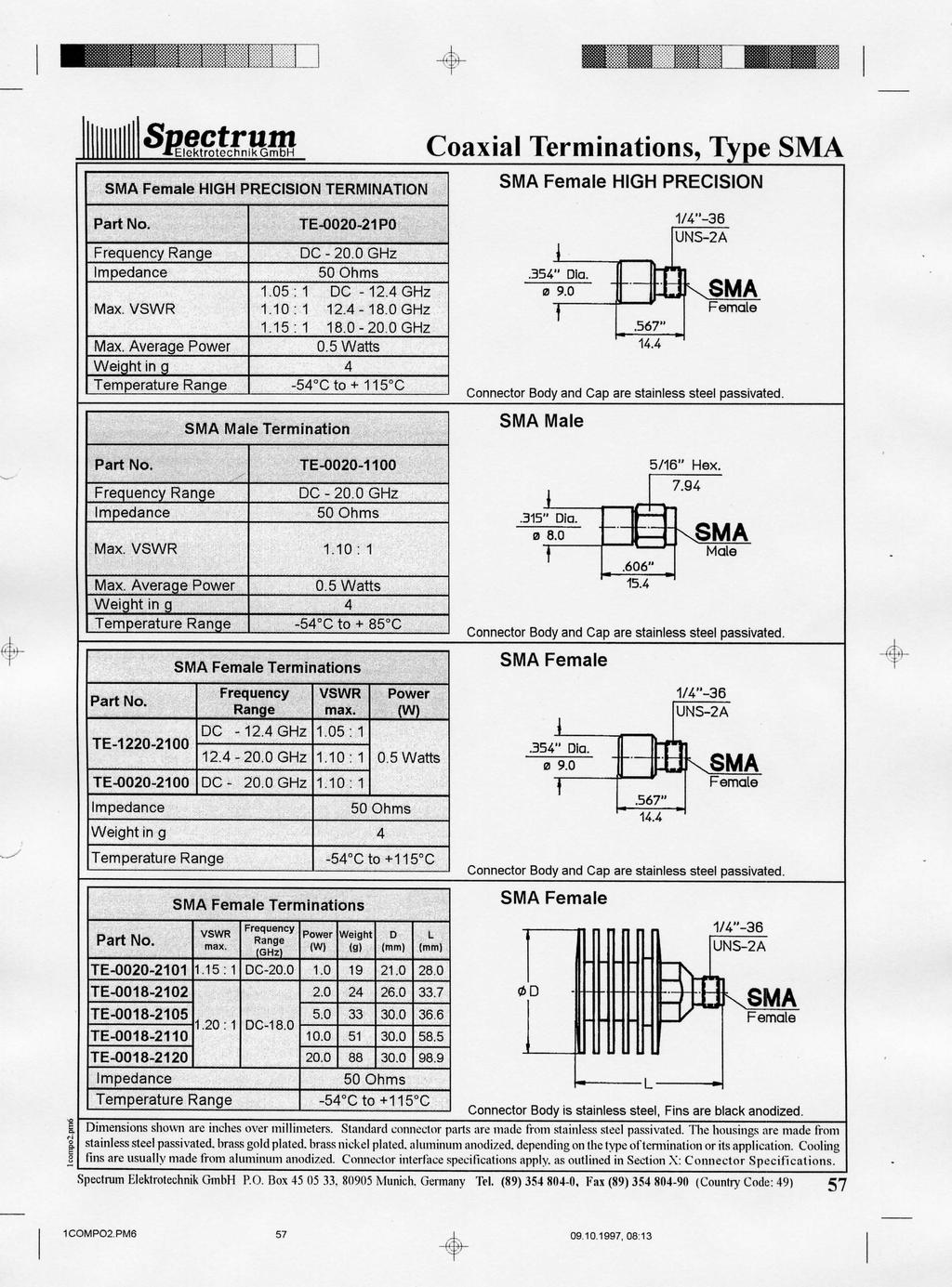
57
58 Type SMA Coaxial Terminations SMA Male Connector Body is stainless steel, Fins are black anodized. VSWR max. TE : 1 SMA Short Circuit-, Open Circuit Terminations SMA Male Terminations Frequency Range (GHz) Power (W) Weight (g) D (mm) L (mm) DC TE TE : DC-18.0 TE TE Impedance 50 Ohms Temperature Range -54 C to +115 C SMA Female Short Circuit Termination Description Frequency Range Weight (g) Short Circuit DC GHz 3 Connector Body and Cap are stainless steel passivated. Impedance Temperature Range 50 Ohms -54 C to +115 C SMA Male Short Circuit Termination Description Frequency Range Weight (g) Short Circuit DC GHz 2 Connector Body and Cap are stainless steel passivated. Impedance Temperature Range 50 Ohms -54 C to +115 C SMA Open Circuit Terminations are not manufactured at this time. It is recommended to use 3.5mm Open Circuit Terminations instead. Please refer to page 45. Dimensions shown are inches over millimeters. Standard connector parts are made from stainless steel passivated. The housings are made from stainless steel passivated, brass gold plated, brass nickel plated, aluminum anodized, depending on the type of termination or its application. Cooling fins are usually made from aluminum anodized. Connector interface specifications apply, as outlined in Section X: Connector Specifications. 58 Spectrum Elektrotechnik GmbH P.O. Box , Munich, Germany Tel. (89) , Fax (89) (Country Code: 49) 1compo2.pm6
59 SMP Female Terminations Frequency Range VSWR max. TE-0018-MP01 DC GHz 1.10 : 1 TE-0040-MP01 DC GHz 1.15 : 1 Power (W) 1 Watt Coaxial Terminations, Type SMP SMP Female Impedance 50 Ohms Weight in g 23 Temperature Range -54 C to +85 C SMP Male Terminations Frequency Range VSWR max. TE-0018-MJ01 DC GHz 1.10 : 1 TE-0040-MJ01 DC GHz 1.15 : 1 Power (W) 1 Watt Impedance 50 Ohms Weight in g 25 Temperature Range -54 C to +85 C SMP Female Open/Short Circuit Terminations Description Frequency Weight Range (GHz) (g) DC Short Circuit DC DC Open Circuit DC Impedance 50 Ohms Temperature Range -54 C to +85 C Connector Body is stainless steel, Cap is gold plated. SMP Male Connector Body is stainless steel, Cap is gold plated. SMP Short/Open Circuit Terminations Short: Connector Body is stainless steel, Cap is nickel plated. Open: Connector Body is stainless steel, Cap is black anodized. 1compo2.pm6 SMP Male Open/Short Circuit Terminations Description Frequency Weight Range (GHz) (g) DC Short Circuit DC DC Open Circuit DC Impedance 50 Ohms Temperature Range -54 C to +85 C Short: Connector Body is stainless steel, Cap is nickel plated. Open: Connector Body is stainless steel, Cap is black anodized. Dimensions shown are inches over millimeters. Standard connector parts are made from stainless steel passivated. The housings are made from stainless steel passivated, brass gold plated, brass nickel plated, aluminum anodized, depending on the type of termination or its application. Cooling fins are usually made from aluminum anodized. Connector interface specifications apply, as outlined in Section X: Connector Specifications. Spectrum Elektrotechnik GmbH P.O. Box , Munich, Germany Tel. (89) , Fax (89) (Country Code: 49) 59
60 Type SPM Coaxial Terminations SPM Female SPM Female Termination TE-0018-PJ00 Connector Body and Cap are stainless steel passivated. SPM Male Frequency Range DC GHz Impedance 50 Ohms Max. VSWR 1.15 : 1 Max. Average Power 0.5 Watts Weight in g 5 Temperature Range -54 C to C SPM Male Termination TE-0018-PM00 Connector Body is stainless steel, Cap is gold plated. SPM Short/Open Circuit Terminations Frequency Range Impedance DC GHz 50 Ohms Max. VSWR 1.15 : 1 Max. Average Power 0.5 Watts Weight in g 4 Temperature Range -54 C to C SPM Female Open/Short Circuit Terminations Description Frequency Range Weight (g) Short Circuit Open Circuit DC GHz In Development In Development Short: Connector Body is stainless steel, Cap is nickel plated. Open: Connector Body is stainless steel, Cap is black anodized. Impedance Temperature Range 50 Ohms -54 C to +85 C SPM Male Open/Short Circuit Terminations Description Frequency Range Weight (g) Short Circuit Open Circuit DC GHz In Development In Development Short: Connector Body is stainless steel, Cap is nickel plated. Temperature Range -54 C to +85 C Open: Connector Body is stainless steel, Cap is black anodized. Dimensions shown are inches over millimeters. Standard connector parts are made from stainless steel passivated. The housings are made from stainless steel passivated, brass gold plated, brass nickel plated, aluminum anodized, depending on the type of termination or its application. Cooling fins are usually made from aluminum anodized. Connector interface specifications apply, as outlined in Section X: Connector Specifications. 60 Impedance 50 Ohms Spectrum Elektrotechnik GmbH P.O. Box , Munich, Germany Tel. (89) , Fax (89) (Country Code: 49) 1compo2.pm6
61 TNC Female HIGH PRECISION TERMINATION Coaxial Terminations, Type TNC TNC Female HIGH PRECISION TE P1 Frequency Range DC GHz Impedance 50 Ohms Max. VSWR 1.10 : 1 Max. Average Power 1 Watt Weight 16 Temperature Range -54 C to C TNC Male HIGH PRECISION TERMINATION Connector Body is stainless steel, Cap is gold plated. TNC Male HIGH PRECISION TE P1 1compo2.pm6 Frequency Range DC GHz Impedance 50 Ohms Max. VSWR 1.10 : 1 Max. Average Power 1 Watt Weight 18 Temperature Range -54 C to C TNC Female Terminations VSWR max. Power Weight D L (W) (g) (mm) (mm) TE TE TE : TE TE Frequency Range DC GHz Impedance 50 Ohms Temperature Range -54 C to +115 C TNC Male Terminations Connector Body is stainless steel, Cap is gold plated. TNC Female Connector Body is stainless steel, Fins are black anodized. TNC Male VSWR Power Weight D L max. (W) (g) (mm) (mm) TE TE TE : TE TE Frequency Range DC GHz Impedance 50 Ohms Temperature Range -54 C to +115 C Connector Body is stainless steel, Fins are black anodized. Dimensions shown are inches over millimeters. Standard connector parts are made from stainless steel passivated. The housings are made from stainless steel passivated, brass gold plated, brass nickel plated, aluminum anodized, depending on the type of termination or its application. Cooling fins are usually made from aluminum anodized. Connector interface specifications apply, as outlined in Section X: Connector Specifications. Spectrum Elektrotechnik GmbH P.O. Box , Munich, Germany Tel. (89) , Fax (89) (Country Code: 49) 61
62 Type TNC Short /Open Circuit Coaxial Terminations TNC Female Open/Short Circuit Terminations Description Frequency Range Weight (g) per MIL-C-87104/ Short Circuit 21 DC GHz Open Circuit 20 Connector Body and Cap are stainless steel passivated. Impedance Temperature Range 50 Ohms -54 C to +85 C TNC Male Open/Short Circuit Terminations Description Frequency Range Weight (g) per MIL-C-87104/ Short Circuit 24 DC GHz Open Circuit 24 Connector Body and Cap are stainless steel passivated. Impedance Temperature Range 50 Ohms -54 C to +85 C TNC Female Open/Short Circuit Terminations Description Frequency Range Weight (g) per MIL-C-87104/ Short Circuit Open Circuit DC GHz In Development In Development Short: Connector Body is stainless steel, Cap is nickel plated. Open: Connector Body is stainless steel, Cap is black anodized. Impedance Temperature Range 50 Ohms -54 C to +85 C TNC Male Open/Short Circuit Terminations Description Frequency Range Weight (g) per MIL-C-87104/ Short Circuit Open Circuit DC GHz In Development In Development Short: Connector Body is stainless steel, Cap is nickel plated. Temperature Range -54 C to +85 C Open: Connector Body is stainless steel, Cap is black anodized. Dimensions shown are inches over millimeters. Standard connector parts are made from stainless steel passivated. The housings are made from stainless steel passivated, brass gold plated, brass nickel plated, aluminum anodized, depending on the type of termination or its application. Cooling fins are usually made from aluminum anodized. Connector interface specifications apply, as outlined in Section X: Connector Specifications. 62 Impedance 50 Ohms Spectrum Elektrotechnik GmbH P.O. Box , Munich, Germany Tel. (89) , Fax (89) (Country Code: 49) 1compo2.pm6
63 TNX Female Termination Coaxial Terminations, Type TNX TNX Female TE Frequency Range DC GHz Impedance 50 Ohms Max. VSWR 1.15 : 1 Max. Average Power 1 Watt Weight in g 33 Temperature Range -54 C to C TNX Male Termination Connector Body and Cap are stainless steel passivated. TNX Male TE Frequency Range Impedance DC GHz 50 Ohms Max. VSWR 1.15:1 Max. Average Power 1 Watt Weight in g 35 Temperature Range -54 C to C TNX Female Open/Short Circuit Terminations Description Frequency Range Weight (g) Connector Body and Cap are stainless steel passivated. TNX Short /Open Circuit Terminations Short Circuit 20 DC GHz Open Circuit 20 Impedance Temperature Range 50 Ohms -54 C to +85 C Connector Body and Cap are stainless steel passivated. 1compo2.pm6 TNX Male Open/Short Circuit Terminations Description Frequency Range Weight (g) Short Circuit 22 DC GHz Open Circuit 22 Impedance 50 Ohms Temperature Range -54 C to +85 C Connector Body and Cap are stainless steel passivated. Dimensions shown are inches over millimeters. Standard connector parts are made from stainless steel passivated. The housings are made from stainless steel passivated, brass gold plated, brass nickel plated, aluminum anodized, depending on the type of termination or its application. Cooling fins are usually made from aluminum anodized. Connector interface specifications apply, as outlined in Section X: Connector Specifications. Spectrum Elektrotechnik GmbH P.O. Box , Munich, Germany Tel. (89) , Fax (89) (Country Code: 49) 63

64 Interested? Please refer to " The '97 Handbook Adapters ". The Precision Adapters are designed for excellent performance. The designs are state-of-the-art, engineered to perfection! 64 Spectrum Elektrotechnik GmbH P.O. Box , Munich, Germany Tel. (89) , Fax (89) (Country Code: 49) 1compo2.pm6

65 Section III 1compo2.pm6 Precision Waveguide Terminations Spectrum Elektrotechnik GmbH P.O. Box , Munich, Germany Tel. (89) , Fax (89) (Country Code: 49) 65
66 Precision Waveguide Terminations 66 INTRODUCTION: Waveguide Terminations or loads, are power absorbing devices. They are matched to 50 Ohms, the characteristic impedance of the transmission line. The standard product line of precision low power Waveguide Terminations are using custom machined load elements for optimum electrical performance. Applications: The waveguide power absorbing devices are needed during test and measurement, can be integrated in components and are used in systems applications. Average Power Handling: This is the maximum allowable CW power to which the unit can be subjected to without suffering permanent damage. The power handling of absorptive units is a function of temperature. High temperature units are supplied with cooling fins or heat sinks or both for better power dissipation. Custom Designs: Spectrum Elektrotechnik GmbH has been designing and supplying Waveguide Terminations to suit standard and particular requirements as well, such as unique lightweight and non typical mechanical outline, e.g. very short length, unusual mounting or special flange requirements, high power terminations, constructed of heavy wall aluminum waveguide and extruded heat sink material, load elements shaped for optimum power handling and heat transfer while maintaining excellent VSWR, or devices engineered for applications in rough environment, etc., etc. Flanges: Waveguide Terminations are available with variety of flanges, meeting the appropriate standard interface specifications. Frequency and Bandwidth: Waveguide Terminations do operate over their waveguide band. In special applications they may be tuned to certain criteria in narrower bands. Materials: Aluminum, copper and brass are the materials used for Waveguide Terminations. For the flanges aluminum and brass are offered. The waveguide itself can be either made from aluminum with aluminum flanges, brass or copper, when a brass flange is used. Operating Temperature Range: The temperature ranges from -54 C to +125 C, or even wider, depending on the application. Precision Waveguide Terminations may have a rather limited temperature range, while the Power Terminations in Systems are usually designed for extreme temperature ranges. The operating temperature however, will reduce the power limit. Standard Products: A standard product line of Waveguide Terminations is available with short deliveries. But if the product needed is not listed, there is always a possibility that the product required has been designed already or that a design, very close to the requirement exists. Therefore, please check your requirements with our sales force or our engineering staff. VSWR: VSWR is the ratio of the reflected signal and the incident signal. It is desired that the loads are ideal, absorbing the power completely. In fact, Waveguide Terminations can be designed and manufactured almost ideally. But the units will still show some reflections and discontinuities within the circuit, as no design is perfect, and manufacturing tolerances do not allow perfect designs anyway. The VSWR of Precision Waveguide Terminations is less than 1.02 : 1 over the full waveguide bandwidth. Spectrum Elektrotechnik GmbH P.O. Box , Munich, Germany Tel. (89) , Fax (89) (Country Code: 49) 1compo2.pm6
67 Precision Waveguide Terminations 1compo2.pm6 Designation Frequency (GHz) Radar Band VSWR max. Power Rating 1) Termination Dimensions (mm) Standard Flange Standard Flange Material Part Number EIA DEF IEC CW (WR) (WG) (R) (W) A B C R UG1711/U Aluminum TP-R437-AL01 UG1716/U Brass TP-R437-BR A UG1713/U Aluminum TP-R340-AL01 UG1712/U Brass TP-R340-BR01 UG1725/U Aluminum TP-R284-AL UG1724/U Brass TP-R284-BR S Aluminum TP-H284-AL R/H Brass TP-H284-BR A UG1727/U Aluminum TP-R229-AL01 UG1726/U Brass TP-R229-BR H UG1729/U Aluminum TP-R187-AL01 UG1728/U Brass TP-R187-BR UG1731/U Aluminum TP-R159-AL01 UG1730/U Brass TP-R159-BR C UG1733/U Aluminum TP-R137-AL01 UG1732/U Brass TP-R137-BR B UG138/U Aluminum TP-R112-AL01 UG51/U Brass TP-R112-BR Aluminum TP-R102-AL01 UG1493/U Brass TP-R102-BR Aluminum TP-R096-AL01 Brass TP-R096-BR01 UG135/U Aluminum TP-R090-AL UG39/U Brass TP-R090-BR X Aluminum TP-H090-AL01 90R/H Brass TP-H090-BR01 Aluminum TP-R075-AL UBR120 Brass TP-R075-BR Aluminum TP-H075-AL01 75R/H Brass TP-H075-BR Aluminum TP-R067-AL Brass TP-R067-BR KU UG1665/U Aluminum TP-R062-AL01 UG419/U Brass TP-R062-BR UBR180 Aluminum TP-R051-AL01 Brass TP-R051-BR K UG597/U Aluminum TP-R042-AL01 UG595/U Brass TP-R042-BR UBR260 Aluminum TP-R034-AL01 Brass TP-R034-BR KA UBR320 Aluminum TP-R028-AL01 UG-599/U Brass TP-R028-BR Aluminum TP-R022-AL01 U383/U Brass TP-R022-BR01 1) At a pressure of one atmosphere. 2) For non Standard Flanges and/or Specifications, a special Part Number will be assigned. Spectrum Elektrotechnik GmbH P.O. Box , Munich, Germany Tel. (89) , Fax (89) (Country Code: 49) 67 2)

68 You are interested in Coaxial Cable Assemblies, connected directly to a waveguide transition? Please call the factory, or your nearest Spectrum Representative.

69 Section IV Coaxial Attenuators 1compo3.pm6 Spectrum Elektrotechnik GmbH P.O. Box , Munich, Germany Tel. (89) , Fax (89) (Country Code: 49) 69
70 Coaxial Attenuators 70 INTRODUCTION: Attenuators are passive linear components, being used to reduce the input power in a system by a certain amount. The ratio of input power versus output power is generally expressed in Decibels (db). Applications: Attenuators are needed to control the microwave energy, mainly during measurement. They are also used to protect systems from excess energy, to extend the dynamic range of measuring equipment, such as power meters, spectrum analyzers, amplifiers, receivers, etc. Attenuation: The attenuation or insertion loss of an attenuator is the ratio of input power versus output power, providing that the input power is generated by a matched generator and the output of the attenuator is delivered into a perfectly matched load. Attenuation Values: The standard attenuation values are available from 0 db to 60 db. In the range of 0 db to 20 db, smaller attenuation ranges are available, e.g. in steps of 1/2 db. Above 20 db and up to 30 db, step sizes of 1 db are standard, while the higher attenuation values are then usually specified by the customer. Average Power Handling: This is the maximum allowable CW power to which the unit can be subjected to without suffering permanent damage, or without changing permanently the specified characteristics of the device. The power handling of absorptive units is a function of temperature. High temperature units are supplied with cooling fins or heat sinks or both for better power dissipation. Connectors: Attenuators are available with a large variety of connectors, meeting the appropriate standard interface specifications, such as MIL-Standards, DIN- or IEC- Specifications, etc. Custom Designs: In addition to the standard terminations shown in this section, Spectrum Elektrotechnik GmbH has been designing and supplying special models to suit particular requirements, such as unique mechanical outline, unusual mounting or special connector requirements, extended frequency operation, special attenuation values, or in between attenuation values, higher power dissipation, harsh environment, etc. Frequency and Bandwidth: Coaxial Attenuators do usually operate over a multi-octave bandwidth. In special applications they may be tuned to certain criteria in narrower bands. High Reliability Components: Most of the attenuators can also be supplied to Customers High Reliability Specifications, environmental, military or governmental requirements, and/ or to customer specified test procedures. Peak Power Handling: This is the maximum allowable Peak power to which the unit can be subjected to without suffering permanent damage, or without changing permanently the specified characteristics of the device. The peak power is transmitted using a certain pulse width and pulse repetition rate. The percentage of transmitted power, compared to CW power is called Duty Cycle Temperature Coefficient: The attenuation value of an attenuator will vary with temperature. The maximum change of attenuation or insertion loss per degree Centigrade over a specified temperature range is called the temperature coefficient. Spectrum Elektrotechnik GmbH P.O. Box , Munich, Germany Tel. (89) , Fax (89) (Country Code: 49) 1compo3.pm6

71 Coaxial Attenuators Spectrum Elektrotechnik GmbH offers custom compiled sets of attenuators, if needed optimized for specific frequency bands. Each attenuator within any set is 100% tested to ensure optimum performance over its full frequency range. To enable the user to maintain these quality attenuators in pristine condition, they are supplied in a nicely finished wooden case. For details please call your nearest Spectrum Representative. 1compo3.pm6 Spectrum Elektrotechnik GmbH P.O. Box , Munich, Germany Tel. (89) , Fax (89) (Country Code: 49) 71
72 Attenuators 7mm to 7mm Attenuator 7mm to 7mm DG-0018-XX90* Frequency Range DC GHz Attenuation Values 3, 6, 10 and 20 db Attenuation Accuracy 3 and 6 db: ± 0.3 db 10 and 20 db: ± 0.5 db DC to 4.0 GHz: 1.12 Max. VSWR 4 to 8.0 GHz: to 18.0 GHz: 1.20 Max. Input Power 2 Watts average at + 25 C 0.5 Watts average at +125 C Operating Temp. Range -54 C to C * XX: Please specify the attenuation value (db) required. BNC Male to BNC Female L N Male to N Female Length L: 1-20 db: 34.5mm db: 41.9mm Attenuator BNC Male to BNC Female DG-0004-XX71* Frequency Range DC GHz Attenuation Values 1-60 db in 1 db increments 1 to 6 db: ± 0.3 db 7 to 10 db: ± 0.5 db Attenuation Accuracy 11 to 20 db: ± 0.75 db 21 to 40 db: ± 1.0 db 41 to 60 db: ± 1.5 db Max. VSWR 1.25 : 1 2 Watts average at + 25 C Max. Input Power 0.5 Watts average at +125 C Operating Temp. Range -54 C to C * XX: Please specify the attenuation value (db) required. 72 Attenuator N Male to N Female DG-0018-XX51* Frequency Range DC GHz Attenuation Values 3, 6, 10 and 20 db Attenuation Accuracy 3 and 6 db: ± 0.3 db 10 and 20 db: ± 0.5 db DC to 4.0 GHz: 1.12 Max. VSWR 4 to 8.0 GHz: to 18.0 GHz: 1.20 Max. Input Power 2 Watts average at + 25 C 0.5 Watts average at +125 C Operating Temp. Range -54 C to C * XX: Please specify the attenuation value (db) required. Spectrum Elektrotechnik GmbH P.O. Box , Munich, Germany Tel. (89) , Fax (89) (Country Code: 49) Date: compo3.pm6
73 SMA Male to SMA Female Attenuators Attenuator SMA Male to SMA Female Frequency Range Attenuation Values Attenuation Accuracy DG-0018-XX11* DC GHz 1-30 db in 1 db increments 1 to 6 db: ± 0.3 db 7 to 20 db: ± 0.5 db 21 to 30 db: ± 1.0 db Max. VSWR f(ghz) Max. Input Power 2 Watts average at + 25 C 0.5 Watts average at +125 C Operating Temp. Range -54 C to C * XX: Please specify the attenuation value (db) required. BNC Male to BNC Female Length L: 1-12 db: 21.8mm db: 25.9mm TNC Male to TNC Female Attenuator TNC Male to TNC Female DG-0018-XX31* Frequency Range DC GHz Attenuation Values 1-60 db in 1 db increments 1 to 6 db: ± 0.3 db Attenuation Accuracy 7 to 20 db: ± 0.5 db 21 to 40 db: ± 1.0 db 41 to 60 db: ± 1.5 db Max. VSWR f(ghz) Max. Input Power 2 Watts average at + 25 C 0.5 Watts average at +125 C Operating Temp. Range -54 C to C * XX: Please specify the attenuation value (db) required. Length L: 1-20 db: 39.9mm db: 46.7mm 1compo3.pm6 YOU NEED SOMETHING DIFFERENT? YOU NEED TECHNICAL ASSISTANCE? You will find immediate support from our Engineering and Marketing Staff. Please give us a call, send us a fax or an , indicating your needs, problems and/or specifications, or contact the nearest Spectrum Representative for more information. Telephone: Fax: {49}(89) {49}(89) CompuServe.com Spectrum Elektrotechnik GmbH P.O. Box , Munich, Germany Tel. (89) , Fax (89) (Country Code: 49) 73

74 We design and manufacture the connectors exactly the way you need them in your System. Interested? Please refer to " The '98 Handbook Microwave Connectors ".

75 Section V Hybrid Housings 1compo3.pm6 Spectrum Elektrotechnik GmbH P.O. Box , Munich, Germany Tel. (89) , Fax (89) (Country Code: 49) 75
76 Hybrid Housing Spectrum Elektrotechnik GmbH manufactures and stocks a variety of excavated aluminum Housings. These housings are used to install RF circuits. Each housing consists of the bottom section and the cover. For prototype applications the housings of Series 1000 and 2000 were designed. Openings for connector locations can easily be fitted when needed. The housings of Series 3000 do have already openings for the connectors at the shown locations. If not specified differently, the housings are made from Al Mg 4.5 Mn. Series 1000 Series 2000 Housing A B C D E F G H K L U V Type (mm) (mm) (mm) (mm) (mm) (mm) (mm) (mm) (mm) (mm) (mm) (mm) GE GE GE GE GE GE GE GE Spectrum Elektrotechnik GmbH P.O. Box , Munich, Germany Tel. (89) , Fax (89) (Country Code: 49) 76 1compo3.pm6

 354 804-0, Fax (89) 354 804-90 (Country")
77 Section VI Gain Amplitude Equalizers 1compo3.pm6 Spectrum Elektrotechnik GmbH P.O. Box , Munich, Germany Tel. (89) , Fax (89) (Country Code: 49) 77
78 Gain Amplitude Equalizers Spectrum Elektrotechnik GmbH has been succesfully developing and manufacturing Gain Amplitude Equalizers showing particular attenuation characteristics, and allowing the compensation of the frequency response of certain components in a system. Gain amplitude equalization is utilized on TWT amplifiers, long coaxial cables, delay lines, oscillators and solid state amplifiers. Spectrum Elektrotechnik GmbH offers its capability to design, develop and to manufacture custom designed Gain Amplitude Equalizers to satisfy distinct requirements. Rugged construction assures high performance in military and commercial applications as well. Fundamentals: The Gain Amplitude Equalizer is an absorptive device having a particular attenuation curve. Two significant categories can be described: Parabolic or Sinusoidal Equalizers. These devices are mainly used at TWT's to compensate the saturated gain. The maximum attenuation is expected in mid band, the minimums are at the band ends. The maximum attenuation can be a few db or even more than 30 db. At the band edge losses of less than 1 db are desirable. Linear or Slope Equalizers. The application of these units is to compensate the frequency dependant loss of long coaxial cable assemblies or delay lines. The maximum loss at the low band edge can be a few db or as much as 30 db, while at high band end edge losses as little as possible are desirable. The loss at the higher frequency limit is usually less than 1 db. Fundamental Parabolic Equalizer Response Fundamental Linear Equalizer Response 78 The parabolic as well as the linear equalizers can be subdivided into three groups: 1.) Fixed Equalizer. The insertion loss curve of the unit is engineered to meet the customer requirements in the system. The attenuation curve is set to the specification. This type of unit is normally used on components that are very predictable. Spectrum Elektrotechnik GmbH P.O. Box , Munich, Germany Tel. (89) , Fax (89) (Country Code: 49) 1compo3.pm6
79 Gain Amplitude Equalizers 1compo3.pm6 2.) 3.) Adjustable Equalizer. The fixed insertion loss versus frequency is specified. All units will be set to meet this predetermined curve. Additionally, if the system requires a similar but a slightly different loss curve, a certain number of adjustments will be available to change the nominal attenuation curve. The type of adjustments can be rising or lowering the maximum attenuation value, shifting the maximum value of the response from the center to lower or higher frequencies, or establishing a change of the attenuation at the band edges, upper, lower or both. A unit can be designed to meet all these requirements for adjustment. Fine Grain Equalizer. This group of devices usually combines with all the characteristics of the "Adjustable Equalizers", but has added a certain number or resonators capable of individual fine grain cancellation. By specification the bandwidths of the resonators can be equal or different, measured at a certain insertion loss characteristic and when its peak l oss is set to a specific value. A typical resonator bandwidth can be any value between 100 MHz and 1.0 GHz measured e.g. at the 0.5 db point, when for example its peak loss is 3 db. The device can be equipped with as many as 20 resonators of different values. The frequency range for tunability of the individual resonators for fine grain cancellation can be specified anywhere in the frequency range of the equalizer. Frequency Range and Bandwidth. The current capability covers the frequency range from 1.0 GHz to over 30.0 GHz. Bandwidths were achieved, ranging from only a few percent to almost three octaves. Several examples are shown on page 80. Spectrum Elektrotechnik GmbH P.O. Box , Munich, Germany Tel. (89) , Fax (89) (Country Code: 49) 79
80 Gain Amplitude Equalizers The diagrams shown on this page are actual data from existing designs Insertion Loss (db) Return Loss (db) 80 Spectrum Elektrotechnik GmbH P.O. Box , Munich, Germany Tel. (89) , Fax (89) (Country Code: 49) 1compo3.pm6
81 Parabolic (half sine) Frequency (GHz) Insertion Loss at upper Frequency Limit (db, max.) Standard Gain Amplitude Equalizers Insertion Loss at Mid-Band (db) Return Loss (db) min. Dimensions (mm) Connectors SMA The insertion loss of the upper frequency limit may be optimized with most models to show loss below 0.7 db. Designs are available to set the differential loss within the limits shown, or even below and above. Return loss can be optimized on special request. Broad band units have been designed showing a return loss of 19 db min. over full bandwidth. The dimensions depend on the differential loss. As soon as the differential loss is specified, the dimensions can be advised. Connectors other than SMA can be supplied upon request. Linear Frequency (GHz) Insertion Loss at upper Frequency Limit (db, max.) Insertion Loss at lower Frequency Limit (db) Return Loss (db) min. Dimensions (mm) Connectors SMA The insertion loss of the upper frequency limit may be optimized with most models to show loss below 0.7 db. Designs are available to set the differential loss within the limits shown, or even below and above. Return loss can be optimized on special request. Broad band units have been designed showing a return loss of 19 db min. over full bandwidth. The dimensions depend on the differential loss. As soon as the differential loss is specified, the dimensions can be advised. Connectors other than SMA can be supplied upon request. 1compo3.pm Spectrum Elektrotechnik GmbH P.O. Box , Munich, Germany Tel. (89) , Fax (89) (Country Code: 49) 81

82 Equalizers 82 Spectrum Elektrotechnik GmbH has been developing state-of-the-art components for a number of very special programs, such as very unique gain amplitude equalizers. The waveguide gain equalizer, as shown above, has been designed for a Ka-Band Jamming System in a military program. The equalizer s sinosoidal loss curve is matched to the gain curves of both, the Driver TWT and the subsequently following Power TWT. The equalizer has very little loss around the band edges, which is desired, as the TWTs do have only little gain there. In midband the loss rises to a maximum, as needed. The curve is smooth and does not show ripples. For delivery, the equalizer is set to a nominal insertion loss curve, as specified. The tuning and set screws are not locked and not sealed, allowing the customer to do final adjustments in the system, several dbs in insertion loss and a certain shift of the insertion loss curve versus frequency. Thus, the equalizer s loss curve can be perfectly matched to the TWTs gain curves for optimum system performance. After the final adjustment the customer can lock and seal the unit. Spectrum Elektrotechnik GmbH P.O. Box , Munich, Germany Tel. (89) , Fax (89) (Country Code: 49) 1compo3.pm6
83 Equalizer Outline Drawings Housing Style H1 Housing Style H2 1compo3.pm6 Housing Style H3 Spectrum Elektrotechnik GmbH P.O. Box , Munich, Germany Tel. (89) , Fax (89) (Country Code: 49) 83
84 Equalizer Outline Drawings Housing Style H4 Housing Style H5 84 Housing Style L1 Spectrum Elektrotechnik GmbH P.O. Box , Munich, Germany Tel. (89) , Fax (89) (Country Code: 49) 1compo3.pm6
85 Equalizer Outline Drawings Housing Style F1 Housing Style F2 1compo3.pm6 Housing Style F3 Spectrum Elektrotechnik GmbH P.O. Box , Munich, Germany Tel. (89) , Fax (89) (Country Code: 49) 85

86 Interested? Please refer to " The 98 Handbook Test Necessities & Accessories ".

87 Section VII DC - Block Connectors 1compo4.pm6 Spectrum Elektrotechnik GmbH P.O. Box , Munich, Germany Tel. (89) , Fax (89) (Country Code: 49) 87
88 DC - Block Connectors 88 INTRODUCTION: DC-Block Connectors consist of a short length of a coaxial transmission line and having a capacitance in series with the center conductor or the outer conductor, or both. The RF is transmitted with negligible reflections and attenuation while the DC or video frequencies are blocked. The DC-Blocks are carefully designed and matched to work to higher frequencies, e.g GHz. Applications: DC-Blocks are used to prevent the flow of direct current or video along a transmission line while permitting the uninterrupted flow of RF. DC-Blocks are mostly needed in systems applications, occasionally also during test and measurement. Average Power Handling: This is the maximum allowable CW power to which the unit can be subjected to without suffering permanent damage. Connectors: DC-Block Connectors are available with a large variety of connectors, meeting the appropriate standard interface specifications, such as MIL-Standards, DIN- or IEC- Specifications, etc. Custom Designs: In addition to the standard Internal DC-Block Connectors, using the SMA connector style, as shown in this section, Spectrum Elektrotechnik GmbH has been designing and supplying special DC-Block Connectors and Adapters to suit particular requirements, such as unique mechanical outline, unusual mounting or special connector requirements, higher power dissipation, rough environment, etc., etc. Frequency and Bandwidth: DC-Block Connectors do usually operate over a multi-octave bandwidth. In special applications they can be designed for certain criteria in narrower bands. High Reliability Components: DC-Block Connectors can also be supplied to Customers High Reliability Specifications, environmental, military or governmental requirements, and/ or to customer specified procedures. Inner Block: The Inner Blocks have a capacitance in series with the center conductor to prevent the flow of DC current along the center line. They are employed when unwanted DC current is monitored on the center conductor, or when DC current is injected onto the center of part of the system and is undesired in the RF section, as it would damage sensitive RF components. Inner-Outer Block: The inner-outer blocks have both, a capacitance in series with the center conductor and a capacitance in series with the outer conductor to prevent the flow of DC current on both conductors. Operating Temperature Range: The temperature ranges usually from -54 C to +115 C, or even wider, depending on the application and the design. Outer Block: The outer blocks have a capacitance in series with the outer conductor to prevent the flow of DC current along the outer shell. Outer blocks are employed when the outer conductor of part of the system is necessary to be operated with a potential. Outline: The outline dimensions of the standard components are usually same as for standard connectors or adapters. Special components can be engineered to customer specifications, showing almost any dimensions as needed in the application. Spectrum Elektrotechnik GmbH P.O. Box , Munich, Germany Tel. (89) , Fax (89) (Country Code: 49) 1compo4.pm6
89 DC - Block Connectors Peak Power Handling: This is the maximum allowable power to which the unit can be subjected to without suffering permanent damage or without changing permanently the specified characteristics of the device. The peak power is transmitted with a certain pulse width and pulse repetition rate. VSWR: VSWR is the ratio of the reflected signal and the incident signal. It is desired that the DC-Blocks have little reflections. But the built-in capacitance will show some reflections and discontinuities within the circuit, and manufacturing tolerances will cause some additional reflections. Outer Conductor Center Conductor Inner Block Outer Conductor Center Conductor Outer Block Outer Conductor Center Conductor 1compo4.pm6 Inner-Outer Block Spectrum Elektrotechnik GmbH P.O. Box , Munich, Germany Tel. (89) , Fax (89) (Country Code: 49) 89
90 DC - Block Connectors (Inner Block) The DC Block is used to prevent the flow of direct current or video along a transmission line while permitting the uninterrupted flow of RF. The unit consists of a short length of coaxial line, having a capacitance in series with the center conductor. The RF is transmitted with negligible reflection or attenuation while the DC or video frequencies are blocked. The outline dimensions of the components are same as for standard connectors and adapters. Special components can be engineered to customer specification. Frequency Range: GHz VSWR: 1.25 max. Insertion Loss:.5 db max. DC Voltage: 100 V max. Capacitance: 100 pf, other values available Operating Temperature: -54 C to +115 C Impedance: 50 Ohms SMA Female, Panel Mount Contact Termination Frequency Range Max. VSWR DC GHz 1.25 max. SMA Male, Panel Mount Contact Termination Frequency Range Max. VSWR DC GHz 1.25 max. Center Conductor Dimensions shown are inches over millimeters. Standard connectors are made from stainless steel passivated. Connector interface specifications apply, as outlined in Section X: Connector Specifications. Spectrum Elektrotechnik GmbH P.O. Box , Munich, Germany Tel. (89) , Fax (89) (Country Code: 49) 1compo4.pm6
91 (Inner Block) DC - Block Connectors SMA Female to SMA Female Frequency Range Max. VSWR DC GHz 1.25 max. SMA Female to SMA Male Frequency Range Max. VSWR DC GHz 1.25 max. SMA Male to SMA Male Frequency Range Max. VSWR DC GHz 1.25 max. SMA Female Flange Mount, Stripline Frequency Range Max. VSWR DC GHz 1.25 max. 1compo4.pm6 Dimensions shown are inches over millimeters. Standard connectors are made from stainless steel passivated. Connector interface specifications apply, as outlined in Section X: Connector Specifications. Spectrum Elektrotechnik GmbH P.O. Box , Munich, Germany Tel. (89) , Fax (89) (Country Code: 49) 91
, or even smaller, and up to 1/2 (12.7mm).")

92 CNCA Cuts your Manufacturing Cost Increases your Quality Standard Features: * Cuts and trims coaxial cables automatically. * Cuts and trims interfaces on Semi-Rigid Cables of diameters from (0.86mm), or even smaller, and up to 1/2 (12.7mm). * Cuts and trims interfaces on Flexible Cables from smallest diameter up to a diameter of 1/2 (12.7mm). * Easy adjustments in cutting lengths and cutting diameters. * Two simultaneously working spindles. * Inexpensive tooling cost. * Easy programming. * Easy set up Munich, Germany P.O. Box Fax:{ 49 }-( 89 ) , Telephone:{ 49 }-( 89 ) country code city code CompuServe.com country code city code

93 Section VIII Coaxial Switches DC GHz 1compo5.pm6 Spectrum Elektrotechnik GmbH P.O. Box , Munich, Germany Tel. (89) , Fax (89) (Country Code: 49) 93
94 Coaxial Switches 94 INTRODUCTION: Coaxial Switches are broadband electromechanical devices, engineered for connecting microwave signals from a common input to two or more outputs. They are designed for either 50 Ohms or 75 Ohms transmission lines. Actuator: This is the electromechanical mechanism that moves the RF contacts from one position to another. Actuator Voltage: The nominal voltage that is needed to switch the RF contacts from one position to another. Arc Suppression Diodes: It is a diode, connected in parallel with the coil. The diode will clip the back spike to 0.7 volts when the coil is deenergized. The cathode of the diode is connected to the side of the coil where the positive voltage is applied, the anode of the diode in connected to ground. Failsafe: The switch is using an actuator that contains a spring back mechanism, providing RF position to one selected position when no voltage is applied. The switch requires maintaining continuous voltage for RF connection to any other position. Indicator Contacts: The contacts are provided to indicate the position of the RF path. The indicator contacts are usually in one-to-one correspondance with the RF contacts. Insertion Loss: Insertion Loss is the difference in power level between input port and the output port it is switched to, the specific path being in the low loss condition. Internal Termination: Any unselected input or output port will be connected to an internal termination of 50 Ohms, or 75 Ohms respectively at 75 Ohms switches. Isolation: Isolation is the difference in power level between an output port that is connected to the input and terminated properly, and an output port that is in the off condition. Latching: The switch is using an actuator that contains a mechanism that always will remain in the last position after switching, regardless whether voltage is maintained or not. Multi-Throw Switch: The switch has one input and more than two outputs. Multi-Throw is another expression for SPNT. RF Power Handling: This is the maximum allowable CW power to which the unit can be subjected to without suffering permanent damage. The rating is based on source and load being ideally 50 Ohms and the operating temperature being within the specified limits. Self Deenergizing: It applies to Latching Switches only: The actuator drive circuit is disconnected and, not using DC current any more after switching has been accomplished. Self Deenergizing, also known as Self Cutoff can be accomplished by using mechanical contacts or integrated drive circuits. SPDT: A switch with one input and two outputs. SPDT means Single Pole Double Through. SPNT: A switch with one input and N outputs. SPNT means Single Pole N Through, where N is the number of outputs. Switching Time: The total switching time depends on the inductive delay in the actuator coil, the transfer time on the RF contacts and the bounce time of the Rf contacts. It is the total amount of time between actuator voltage being applied and the completion of the switching. Spectrum Elektrotechnik GmbH P.O. Box , Munich, Germany Tel. (89) , Fax (89) (Country Code: 49) 1compo5.pm6
95 Coaxial Switches Transfer Switch: A four port device, providing two independent pairs of RF paths. The pairs are actuated simultaneously. VSWR: Voltage Standing Wave Ratio is the ration of the reflected signal and the incident signal. Every microwave component shows reflections and discontinuities within the circuit, as no design is perfect, and manufacturing tolerances do not allow perfect designs anyway. Ordering Information for Coaxial Switches A B - C D E F - G H J K F=Failsafe L=Latching Input/ Output Port Conf. as specified on the outline drawings. Input number max. 9 Output number max. 9 Power Supply E = 5 V L = 12 V N = 24 V 0 = 15 V Z = 26 V Frequency Range B = 0.2 GHz C = 0.5 GHz D = 1.2 GHz E = 1.5 GHz F = 2.0 GHz G = 3.0 GHz Connectors 50 Ohms Connectors 75 Ohms Please use Connector code as per table below. 1compo5.pm6 E 0 = no Indicators R = Indicators F A = unused ports are terminated 0 = unused ports are not terminated T = Transfer Switch J K Connectors 50 Ohms 03 = 1.4/ = 1.8/5.6 - Female 05 = 1.8/5.6 - Male 11 = SMA - Male 21 = SMA - Female 31 = TNC - Male 41 = TNC - Female 51 = N - Male 61 = N Female 71 = BNC - Male 81 = BNC - Female Connectors 75 Ohms A1 = 1.6/5.6 - Male A2 = 1.6/5.6 - Female 7B = BNC - Male 8B = BNC - Female 7N = N - Male 8N = N - Female Spectrum Elektrotechnik GmbH P.O. Box , Munich, Germany Tel. (89) , Fax (89) (Country Code: 49) 95
96 SPDT Switches Description: The SPDT switch is a broadband electromechanical, coaxial switch, designed to switch microwave signals from a common input to either of two outputs,.designed for 50 and 75 Ohms transmission lines respectively. The switch is set up with minimum size, compatible with BNC, TNC, N, and SMA connector spacing. The SPDT comes with either failsafe or latching actuator. SPDT Ordering Information F L A B C No. of Inputs No. of Outputs 0 R A 0 E 0 L Z N B C D E F G A1 7N A2 8N B B F=Failsafe L=Latching Input/Output Port Config. A,B = unused ports are not terminated C = unused ports are terminated = without indicators R = with indicators A = unused ports are terminated 0 = unused ports are not terminated - Power Supply E = 5 L = 12 V N = 24 V 0 = 15 V Z = 26 V V Frequency Range B = 0.2 GHz C = 0.5 GHz D = 1.2 GHz E = 1.5 GHz F = 2.0 GHz G = 3.0 GHz Connectors 50 Ohms Connectors 75 Ohms Explanation of Connector codes as per Table below.* Specifications RF Contacts Break before make Actuator Voltage 5, 12, 15, 24 and 26 VDC Failsafe: Depending on voltage and configuration, Actuator Current Latching: { please refer to the specific data sheet. Switching Time 10 msec. maximum at nominal voltage Weight Depending on housing/connector configuration Temperature Range -50 C to +60 C Life 10 5 cycles RF Power Handling 5 Watts - Indicator Circuits Port Configuration A and B - Special Actuator Voltages - TTL Compatible Drivers Optional Features - Arc Suppression Diodes - Power Connectors - Internal Termination different Port Configuration available. Connectors 50 Ohms 03 = 1.4/ = 1.8/5.6-Female 05 = 1.8/ 5.6-Male 11 = SMA-Male 21 = SMA-Female 31 = TNC-Male 41 = TNC-Female 51 = N-Male 61 = N Female 71 = BNC-Male 81 = BNC-Female Connectors 75 Ohms A1 = 1.6/5.6-Male A2 = 1.6/5.6-Female 7B = BNC-Male 8B = BNC-Female 7N = N-Male 8N = N-Female RF Performance Frequency DC GHz GHz GHz GHz VSWR (maximum) 1.20 : : : : 1 Insertion Loss (maximum) 0.2 db 0.4 db 0.5 db 0.6 db Isolation (minimum) 70 db 60 db 50 db 40 db * If you need different connectors at the Input/Output, a special part number will be assigned. 96 Spectrum Elektrotechnik GmbH P.O. Box , Munich, Germany Tel. (89) , Fax (89) (Country Code: 49) 1compo5.pm6
97 SPDT Coaxial Switches, Housing Styles SPDT, Port Configuration/Housing Style A (unused ports are not terminated) 1compo5.pm6 SPDT, Port Configuration/Housing Style B (unused ports are not terminated) Spectrum Elektrotechnik GmbH P.O. Box , Munich, Germany Tel. (89) , Fax (89) (Country Code: 49) 97
98 Coaxial Switches, Housing Styles, SPDT SPDT, Port Configuration/Housing Style C (unused ports are terminated) 98 Spectrum Elektrotechnik GmbH P.O. Box , Munich, Germany Tel. (89) , Fax (89) (Country Code: 49) 1compo5.pm6
99 SPDT Coaxial Basic Schematics Failsafe, SPDT Position RF-Continuity De-Energized IN - 2 Energized IN - 1 Failsafe, SPDT with Indicator Position RF-Continuity Indicator De-Energized IN - 2 A - C Energized IN - 1 B - C Latching, SPDT Position RF-Continuity Voltage 1 IN C 2 IN C Latching, SPDT with Indicator Position RF-Continuity Voltage Indicator 1 IN C A - C 2 IN C B - C 1compo5.pm6 Spectrum Elektrotechnik GmbH P.O. Box , Munich, Germany Tel. (89) , Fax (89) (Country Code: 49) 99
100 Multi - Through Switches Description: The SPNT switch is a broadband electromechanical coaxial switch, designed to switch microwave signals from one common port to anyone of 3, 4, 5, 6 or more ports. Overall size has been optimized for minimum spacing of N connectors and the switch is designed for 50 or 75 Ohms transmission line systems, respectively. Multi - Through Switches Ordering Information F L A B C No. of Inputs No. of Outputs 0 R A 0 E 0 L Z N B C D E F G A1 7N A2 8N B B F=Failsafe L=Latching A - Port configuration/ housing style for SP3T. 1 N Please specify No. of outputs. 0 = without indicators R = with indicators A = unused ports are terminated 0 = unused ports are not terminated - Power Supply E = 5 V L = 12 V N = 24V 0 = 15 V Z = 26 V Frequency Range B = 0.2 GHz C = 0.5 GHz D = 1.2 GHz E = 1.5 GHz F = 2.0 GHz G = 3.0 GHz Connectors 50 Ohms Connectors 75 Ohms Explanation of Connector codes as per Table below.* Specifications RF Contacts Break before make Actuator Voltage 5, 12, 15, 24 and 26 VDC Failsafe: Depending on voltage and configuration, Actuator Current Latching: { please refer to the specific data sheet. Switching Time 10 msec. maximum at nominal voltage Weight Depending on housing/connector configuration Temperature Range -50 C to +60 C Life 10 5 cycles RF Power Handling 5 Watts Optional Features - Indicator Circuits - Special Actuator Voltages - TTL Compatible Drivers - Arc Suppression Diodes - Power Connectors - Internal Terminations Connectors 50 Ohms 03 = 1.4/ = 1.8/5.6-Female 05 = 1.8/ 5.6-Male 11 = SMA-Male 21 = SMA-Female 31 = TNC-Male 41 = TNC-Female 51 = N-Male 61 = N Female 71 = BNC-Male 81 = BNC-Female Connectors 75 Ohms A1 = 1.6/5.6-Male A2 = 1.6/5.6-Female 7B = BNC-Male 8B = BNC-Female 7N = N-Male 8N = N-Female RF Performance Frequency DC GHz GHz GHz GHz VSWR (maximum) 1.20 : : : : 1 Insertion Loss (maximum) 0.2 db 0.4 db 0.5 db 0.7 db Isolation (minimum) 70 db 60 db 50 db 40 db * If you need different connectors at the Input/Output, a special part number will be assigned. 100 Spectrum Elektrotechnik GmbH P.O. Box , Munich, Germany Tel. (89) , Fax (89) (Country Code: 49) 1compo5.pm6
101 SP3T Coaxial Switches, Housing Styles SP3T, Port Configuration/, Housing Style A 1compo5.pm6 Latching, SP3T with Indicator Latching, SP3T Spectrum Elektrotechnik GmbH P.O. Box , Munich, Germany Tel. (89) , Fax (89) (Country Code: 49) 101
102 Transfer Switches Description: The transfer switch is designed for use in 50 Ohms and 75 Ohms coaxial transmission lines respectively, operating over frequencies, ranging from DC to 3.0 GHz. The switch is designed for minimum size, compatible with N connector spacing. Transfer Switches Ordering Information F L A No. of Inputs No. of Outputs 0 R T E 0 L Z N B C D E F G A1 7N A2 8N B B F=Failsafe L=Latching - A 2 2 Port configuration/ housing style. 0 = without indicators R = with indicators T - Power Supply E = 5 V L = 12 V N = 24V 0 = 15 V Z = 26 V Frequency Range B = 0.2 GHz C = 0.5 GHz D = 1.2 GHz E = 1.5 GHz F = 2.0 GHz G = 3.0 GHz Connectors 50 Ohms Connectors 75 Ohms Explanation of Connector codes as per Table below.* Specifications RF Contacts Break before make Actuator Voltage 5, 12, 15, 24 and 26 VDC Failsafe: Depending on voltage and configuration, Actuator Current Latching: { please refer to the specific data sheet. Switching Time 10 msec. maximum at nominal voltage Weight Depending on housing/connector configuration Temperature Range -50 C to +60 C Life 10 5 cycles RF Power Handling 5 Watts Optional Features - Indicator Circuits - Special Actuator Voltages - TTL Compatible Drivers - Arc Suppression Diodes - Power Connectors - Internal Terminations Connectors 50 Ohms 03 = 1.4/ = 1.8/5.6-Female 05 = 1.8/ 5.6-Male 11 = SMA-Male 21 = SMA-Female 31 = TNC-Male 41 = TNC-Female 51 = N-Male 61 = N Female 71 = BNC-Male 81 = BNC-Female Connectors 75 Ohms A1 = 1.6/5.6-Male A2 = 1.6/5.6-Female 7B = BNC-Male 8B = BNC-Female 7N = N-Male 8N = N-Female RF Performance Frequency DC GHz GHz GHz GHz VSWR (maximum) 1.20 : : : : 1 Insertion Loss (maximum) 0.2 db 0.4 db 0.5 db 0.6 db Isolation (minimum) 70 db 60 db 50 db 40 db * If you need different connectors at the Input/Output, a special part number will be assigned. 102 Spectrum Elektrotechnik GmbH P.O. Box , Munich, Germany Tel. (89) , Fax (89) (Country Code: 49) 1compo5.pm6
103 Transfer Switches, Housing Styles Transfer Switch, Port Configuration/Housing Style A 1compo5.pm6 Latching, Transfer with Indicator Latching, Transfer Position RF-Continuity Voltage Indicator Position RF-Continuity Voltage Indicator C A - C C A - C C B - C C B - C Spectrum Elektrotechnik GmbH P.O. Box , Munich, Germany Tel. (89) , Fax (89) (Country Code: 49) 103

104 Interested? Please refer to " The '97 Handbook Adapters ".

105 Section IX 1compo6.pm6 Special Products & Services Spectrum Elektrotechnik GmbH P.O. Box , Munich, Germany Tel. (89) , Fax (89) (Country Code: 49) 105
106 Special Products & Services Design and Engineering: Spectrum Elektrotechnik GmbH is a very innovative Company. It employs a strong and successful team of experienced engineers. If your application requires a product that is not available as standard, Spectrum Elektrotechnik GmbH is the Company to contact. Our engineers are ready and willing and capable to listen to your problem and they will try their best to propose something that will fit your needs perfectly. There is also a possibility that we may have solved already a similar problem for somebody else and that we have a solution available, almost off the shelf. Following a few examples of areas where our engineering staff has proposed and designed and manufactured hardware to the customers requirements, or has developed successfully Products to widen and strengthen our Product Range: The Cable Assembly Group: Designing and manufacturing of Low Loss Cable Assemblies, Extra Light Weight Assemblies, Phase & Amplitude Matched Cable Assemblies, High Velocity and Thermal Stable Dielectrics, Delay Lines, etc. The Connector Group: Designing and manufacturing successfully new Connector Series, e.g. of Types SBX, SBY and SPM, connectors that were not available at all with the physical and electrical performance as needed for specific programs. Adapters for special applications were designed to fit exactly the customer's needs, mechanically and electrically. A whole new Product Line was developed and successfully introduced to the market: the PUSH-ON Connectors and Adapters for series 3.5mm, K*, SMA, N and TNC, using 50 Ohms impedance, and for F, N and TNC as well, using 75 Ohms impedance. The Component Group: Besides the Standard Product Lines, Spectrum Elektrotechnik GmbH offers Engineering and Manufacturing Services, to design and manufacture Components exactly to Customer's Specification. Whatever cannot be found in anybody else`s catalog, Spectrum Elektrotechnik GmbH is definitely worthwhile to contact. There is even always a possibility that a similar product has already been designed for somebody else. The Table to the right shows the areas where Spectrum Elektrotechnik GmbH has successfully designed and manufactured products to customer specifications. On pages 108 through 146 detailed information will be given on these components. Process Engineering: This Group has been developing tools and machines that are needed in manufacturing but were not available on the market as standard. Currently the design, manufacturing and testing of an Automatic Cable Cutting and Stripping Machine has been completed and the machine has been introduced to the market as CNCA-700. Quick Response Manufacturing: The Quick Response Manufacturing is another good example for the commitment to providing excellent Customer Service. The Quick Response Group was implemented to react immediately to customer's needs. Sometimes Products will be shipped within 24 hours. All Products manufactured in the Quick Response Area will meet the same Quality Standards as all the other products, they are submitted to the same inspection. 106 Spectrum Elektrotechnik GmbH P.O. Box , Munich, Germany Tel. (89) , Fax (89) (Country Code: 49) * 'K' Connector is a trademark of Wiltron Company. 1compo6.pm6
107 Special Products & Services Product Please refer to page(s): Adapter Sets Antennas Blind Mate Connectors Calibration Kits Circulators & Isolators Couplers Custom Connectors/Adapters Delay Lines Detectors Directional Couplers Impedance Transformers Interface Gauges 116 Isolators & Circulators Lightening Surge Suppressors Limiters Phase Stable Assemblies Precision Mismatches PUSH - ONs RF-Multipin Connector SQ Rotary Joints compo6.pm6 Supercomponents Torque Wrenches 117 Spectrum Elektrotechnik GmbH P.O. Box , Munich, Germany Tel. (89) , Fax (89) (Country Code: 49) 107
108 Adapter Sets Spectrum Elektrotechnik GmbH offers a standard range of precision adapter sets. Each set comprises a commonly used grouping of series and inter-series adapters. Each adapter within any set is 100% tested, and ensures low reflection and optimum phase performance over its full frequency range. To enable the user to maintain these quality adapters in pristine condition, they are supplied in a nicely finished wooden case. Customers can also specify adapters for their own custom compiled sets. For details please call your Spectrum Representative. Between Series Kit 7mm, consisting of the following Precision Adapters: 1 Adapter straight 1 Adapter straight 1 Adapter straight 1 Adapter straight 1 Adapter straight 1 Adapter straight 1 Adapter straight 1 Adapter straight 7 mm to 2.4 mm-female: 7 mm to 2.4 mm-male: 7 mm to K*-Female: 7 mm to K* -Male: 7 mm to 3.5-Female: 7 mm to 3.5-Male: 7 mm to SMA-Female: 7 mm to SMA-Male: SET7-MINI-S1 P/N 8001-HF90-02 P/N 8001-HM90-02 P/N 8001-KF90-02 P/N 8001-KM90-02 P/N P/N P/N P/N Between Series Kit Type N, consisting of the following Precision Adapters: 1 Adapter straight 1 Adapter straight 1 Adapter straight 1 Adapter straight 1 Adapter straight 1 Adapter straight 1 Adapter straight 1 Adapter straight N-Fem. to 3.5 mm-fem.: N-Fem. to 3.5 mm-male: N-Male to 3.5 mm-fem.: N-Male to 3.5 mm-male: N-Female to SMA-Fem.: N-Female to SMA-Male: N-Male to SMA-Fem.: N-Male to SMA-Male: SETN-MINI-S1 P/N P/N P/N P/N P/N P/N P/N P/N Between Series Kit 7mm, consisting of the following Precision Adapters: 2 Adapter straight 2 Adapter straight 2 Adapter straight 2 Adapter straight 7 mm to 3.5-Female: 7 mm to 3.5-Male: 7 mm to SMA-Female: 7 mm to SMA-Male: SET7-MINI-S2 P/N P/N P/N P/N Between Series Kit BNC, consisting of the following Precision Adapters: 1 Adapter straight 1 Adapter straight 1 Adapter straight 1 Adapter straight BNC-Fem. to SMA-Fem.: BNC-Fem. to SMA-Male: BNC-Male to SMA-Fem.: BNC-Male to SMA-Male: SETB-TSMA-S1 P/N P/N P/N P/N Between Series Kit 7mm, consisting of the following Precision Adapters: 2 Adapter straight 2 Adapter straight 2 Adapter straight 2 Adapter straight 7 mm to TNC-Female: 7 mm to TNC-Male: 7 mm to N-Female: 7 mm to N-Male: Between Series Kit 7mm, consisting of the following Precision Adapters: 1 Adapter straight 1 Adapter straight 1 Adapter straight 1 Adapter straight 1 Adapter straight 1 Adapter straight 1 Adapter straight 1 Adapter straight 7 mm to 3.5 mm-female: 7 mm to 3.5 mm-male: 7 mm to SMA-Female: 7 mm to SMA -Male: 7 mm to TNC-Female: 7 mm to TNC-Male: 7 mm to N-Female: 7 mm to N-Male: Between Series Kit N-TNC, consisting of the following Precision Adapters: 2 Adapter straight 2 Adapter straight 2 Adapter straight 2 Adapter straight N-Female to TNC Fem.: N-Female to TNC Male: N-Male to TNC Female: N-Male to TNC Male: SET7-TNCN-S1 P/N P/N P/N P/N SET7-UNIV-S1 P/N P/N P/N P/N P/N P/N P/N P/N SETN-TTNC-S1 P/N P/N P/N P/N SETT-TSMA-S1 Between Series Kit TNC-SMA, consisting of the following Precision Adapters: 2 Adapter straight 2 Adapter straight 2 Adapter straight 2 Adapter straight TNC Fem. to SMA-Fem.: TNC Fem. to SMA-Male: TNC Male to SMA-Fem.: TNC Male to SMA-Male: P/N P/N P/N P/N In-Series Kit Type SMA, consisting SETS-TSMA-S1 of the following Precision Adapters: 1 Adapter straight SMA-Fem. to SMA-Fem.: P/N Adapter straight SMA-Fem. to SMA-Male: P/N Adapter straight SMA-Male to SMA-Male: P/N Adapter radius angle SMA-Fem. to SMA-Fem.: P/N Adapter radius angle SMA-Fem. to SMA-Male: P/N Adapter radius angle SMA-Male to SMA-Male: P/N In-Series Kit, Type N, consisting of the following Precision Adapters: 2 Adapter straight 2 Adapter straight 2 Adapter straight N-Female to N-Female: N-Female to N-Male: N-Male to N-Male: In-Series Kit Type TNC, consisting of the following Precision Adapters: 2 Adapter straight 2 Adapter straight 2 Adapter straight TNC-Fem. to TNC Fem.: TNC-Fem. to TNC Male: TNC-Male to TNC Male: SETN-TYPN-S1 P/N P/N P/N SETT-TTNC-S1 P/N P/N P/N How to order your Personal Set: Please use the temporary P/N: SET-PERS, and specify all the Adapters you want to include in your Set. The individual Kit will be showing your name plate, identifying your own compiled Set. 108 Spectrum Elektrotechnik GmbH P.O. Box , Munich, Germany Tel. (89) , Fax (89) (Country Code: 49) 1compo6.pm6

109 Adapter Sets Customers may specify Adapters for their own custom compiled sets. Adapters can be ordered optimized for specific frequency bands as well. 1compo6.pm6 For more information, please refer to " The '97 Handbook Adapters ". Spectrum Elektrotechnik GmbH P.O. Box , Munich, Germany Tel. (89) , Fax (89) (Country Code: 49) 109
110 Antennas INTRODUCTION: Antennas are employed to couple electromagnetic energy between free space propagation and the energy received or transmitted as a guided wave by a radar system. Antenna dimensions of several wavelengths may be needed to confine an adequate amount of energy. Application: Most antennas are used to serve as both, transmitters and receivers of microwave systems. Most systems require an antenna that tends to concentrate the transmitted energy into a small solid angle, or to receive energy from a specific direction. Antenna Gain: The ability of an antenna to concentrate energy in a particular direction or to be more sensitive to energy incident from a specific direction is described in terms of the antenna gain. Denoted only as the gain, the exact definition would be the power gain of an antenna, which includes losses associated with the antenna, such as ohmic and RF heating. Antenna Radiation Pattern: The spatial distribution of energy when plotted on a relative basis is called the antenna radiation pattern and it is a measure of the power per unit area, also called the power pattern. When measuring the unit per solid angle in a given direction, it is called the radiation intensity pattern. Average Power Handling: This is the maximum allowable power to which the antenna can be subjected to without suffering permanent damage. Connectors: Antennas can be supplied with almost any connector or waveguide configuration, supposing that frequency range and power level are within the connector/waveguide limits. Custom Designs: Spectrum Elektrotechnik GmbH has been supplying only antennas that are designed to special requirements. At the time being the company does not compete with standard products that are available from various suppliers. Frequency and Bandwidth: The frequency and bandwidth depend on many parameters, the type and physical structure, dimensions and materials of the antenna, the gain, beam width, polarization, radome, material, shape, etc. Operating Temperature Range: The temperature range is usually very wide, especially for outdoor applications. Polarization: The direction of the polarization is defined as the direction of the electric field vector. The principal planes of the antenna pattern are associated with a linearly polarized component of the electric field and are commonly designated as horizontal or vertical polarizations, so that the antenna patterns are specified as being either horizontal or vertical patterns. For circular polarization the electric field rotates at a frequency equal to the frequency of the propagating wave, e.g. right handed when the direction of rotation of the electric-field vector is clockwise when viewed as a receding wave away from the antenna. VSWR: VSWR is the ratio of the reflected signal and the incident signal, when looking into the antenna from system side. The VSWR for receive and transmit of an antenna may be different. 110 Spectrum Elektrotechnik GmbH P.O. Box , Munich, Germany Tel. (89) , Fax (89) (Country Code: 49) 1compo6.pm6
111 ISM Band Antenna The Planar Antenna has been designed for OEM - Applications and is operating in the 2.4 GHz Band. The small dimensions and the rugged construction of the device are ideally suited for all applications regarding Wireless Telecommunication such as LAN, PBXs, PCS, PCN, Laptops, etc. The unique design utilizes a board construction that allows lowest cost at high volume. The Antenna can be optimized for any frequency in the ISM band. Specification Model-No. AN Frequency Range 2.45 GHz Antenna Gain 3.5 dbi Polarization linear Dimensions 55mm * 55mm 1compo6.pm6 Connector SMA female Spectrum Elektrotechnik GmbH P.O. Box , Munich, Germany Tel. (89) , Fax (89) (Country Code: 49) 111
112 Blind Mate Connectors INTRODUCTION: Regular connectors have to be aligned properly for mating purposes. Whenever the connecting parts are fully visible, there is no problem in alignment. But putting connectors together, without seeing and feeling them, is usually a challenge and always almost impossible, if they are not designed for such purpose. With Blind Mate Connectors there is at least one of the two mating connectors designed to move or shift in location for self aligning, proper and safe mating purposes. Frequency: Blind Mate Connectors do usually operate over a wide frequency range. But the bigger the connector series, the lower the upper frequency limit becomes, as known by the law of physics. The SBX works to 8.0 GHz, and it can take a tremendous lot of power. The SBY operates safely to 12.0 GHz, the BMA to 18.0 GHz, and the SMP to 40.0 GHz. VSWR: VSWR is the ratio of the reflected signal and the incident signal, caused by reflections and discontinuities within the circuit, as no design is perfect, and manufacturing tolerances do not allow perfect devices anyway. But it is the fact that the Blind Mate Connection has a much lower VSWR, compared to the VSWR as seen on most cable assemblies. Operating Temperature Range: The standard temperature range is normally specified from -54 C to +125 C. Depending on the application, the temperature range can be widened by using special design techniques and selecting appropriate materials and dielectrics. Average Power Handling: This is the maximum allowable CW power to which the unit can be subjected to without suffering permanent damage. Standard Connectors: The complete line of Blind Mate Connectors will be shown in the "The 98 Handbook Quick Connections". The " 97 Handbook Adapters" lines out a number of in-series and between-series adapters and references complete dimensions of the interfaces. Custom Designs: Spectrum Elektrotechnik GmbH will always be designing and supplying connectors to suit particular requirements, such as low VSWR, unique mechanical outline, unusual mounting, better power dissipation, characteristic impedance other than 50 Ohms, rough environment, etc., etc. If a special unit is needed, it is recommended to contact our sales force or the engineering department, as there is always a good chance that a similar problem was already solved for somebody else, or only a minor change is needed to an existing design in order to meet the new requirement. Applications: Blind Mate Connectors are used to interconnect components, replacing cable assemblies. The advantages are: lower cost, less insertion loss and a more rugged construction. Blind mate connectors are often used on the back of drawers as well. Blind Mate Connectors are advanced connections for the newer systems. Full details, interface mating dimensions and product information are shown in : " The 97 Handbook Adapters", " The 98 Handbook Quick Connections" and " The 98 Handbook Microwave Connectors". 112 Spectrum Elektrotechnik GmbH P.O. Box , Munich, Germany Tel. (89) , Fax (89) (Country Code: 49) 1compo6.pm6
113 Interfaces, Blind Mate Connectors SBX Female SBY Female Frequency: DC GHz min. Frequency: DC GHz min. SBX Male SBY Male Frequency: DC GHz min. Frequency: DC GHz min. BMA Female SMP Female Frequency: DC GHz min. SMP Male full detent SMP Male limited detent Frequency: DC GHz min. BMA Male SMP Male smooth bore SMP Male 1compo6.pm6 Frequency: DC GHz min. Spectrum Elektrotechnik GmbH P.O. Box , Munich, Germany Tel. (89) , Fax (89) (Country Code: 49) 113
114 Calibration Kits INTRODUCTION: Vector Network Analyzers are needed to accurately determine the RF Characteristics of Microwave Components. For true and accurate measurement the Network Analyzers have to be calibrated with known standards. As Network Analyzers have the ability to reduce error terms to negligible values, they depend on the quality and the integrity of the Calibration Standards used. Spectrum Elektrotechnik GmbH produces a comprehensive line of Coaxial Calibration Kits, incorporating most accurate and stable calibration standards. A true and precise evaluation of the performance of the device under test can therefore be ensured. Methodology: Two different techniques are commonly used for coaxial calibration, the open-short-load-through calibration technique and the Through-Reflective-Line (TRL), also known as Line-Reflective-Line (LRL). Open-Short-Load-Through: Calibration Standards, using this method, do consist of high precision male and female Opens, Shorts and fixed wideband Loads. As an option sliding loads can be supplied. Through-Reflective-Line: These Calibration Kits consist of high precision shorts and ideal through lines. Calibration Kit Components: The most important Components of the Calibration Kits are the Calibration Standards. Discs will be supplied, showing the data on the properties of the Calibration Standards. The discs are ready to be used on the Scalar Network Analyzers of Hewlett Packard and Wiltron. But also other components will be needed during testing and therefore be included in the Kit as well, such as precision adapters, torque wrenches, regular wrenches, as needed for any hex supplied with the components in the calibration kit. A set of precision gauges will be included, for checking the interfaces of the devices before test. Interface Gauges: Before testing any device, the interfaces of the connectors have to be checked to ensure that they meet the appropriate specification. Protruding interfaces will damage the mating connector. Interfaces that are recessed below the allowed level will lead to useless test results. Torque Wrench: In order to ensure accurate testing the connectors of the components under test always should be torqued for proper connection, as outlined in the applicable specifications and to avoid damaging the connectors by over torquing. Coaxial Connector Series: Kits are available for the following connector series: 3.5mm, 7mm, K*, N, SMP and TNC. In addition calibration components have been designed and manufactured for the series BNC, C, HN and SC. Phase Stable Test Cable Assemblies: Spectrum Elektrotechnik GmbH offers phase stable test cable assemblies, fitted with the appropriate connector on one end of the assembly to connect directly with Hewlett Packards or Wiltrons Network Analyzers, using NMD 2.4mm, 3.5mm or K*. For the other end of the cable assembly a wide variety of connectors can be selected, such as 2.4mm, 3.5mm, K*, SMP, N, TNC, etc. More information can be derived from " The '98 Handbook Test Accessories and Necessities ". 114 Spectrum Elektrotechnik GmbH P.O. Box , Munich, Germany Tel. (89) , Fax (89) (Country Code: 49) * 'K' Connector is a trademark of Wiltron Company. 1compo7.pm6


115 Calibration Kits 1compo7.pm6 Calibration Kits are designed and manufactured to the highest standards. A Calibration Kit should not only include the standards needed for the calibration. It is furthermore very helpful to have handy the necessary adapters, gauges and wrenches as well. Every Calibration Kit is supplied with a parts list, identifying the individual components and their part numbers. A certificate guarantees that the calibration Kit meets the appropriate standards and requirements. Spectrum Elektrotechnik GmbH P.O. Box , Munich, Germany Tel. (89) , Fax (89) (Country Code: 49) 115

116 Interface Gauges Interface Gauges: Before testing any device, the dimensions of the interfaces of the connectors should be checked, to ensure that they do meet specification. Protruding interfaces will damage the mating connector. Interfaces that are recessed below the allowed level will lead to useless test results. Interface gauges are usually supplied in sets of 2 to 4 units, for checking the center contacts of the male and female connectors and their dielectrics for protrusion and recession. Interface gauges are availabe for most connector series, such as 2.4mm, 3.5mm, 7mm, N, SC, SMA, TNC, etc. More information can be found in " The '98 Handbook Test Necessities and Accessories ". 116 Spectrum Elektrotechnik GmbH P.O. Box , Munich, Germany Tel. (89) , Fax (89) (Country Code: 49) 1compo7.pm6

117 Torque Wrenches Torque Wrenches: In order to ensure accurate testing of components, the connectors always should be torqued for optimum connection, as outlined in the applicable specifications, to avoid useless test results because of loose connectors, or from damaged connectors because of over torquing. Torque Wrenches are availabe for most connector series, such as 2.4mm, 3.5mm, 7mm, N, SMA, TNC, etc. The torque wrenches may also be supplied in sets for other connector series, clearly marked and supplied in a wooden box. The customer also may specify the wrenches that are to be included in his personal box. More information can be found in " The '98 Handbook Test Necessities and Accessories ". 1compo7.pm6 Spectrum Elektrotechnik GmbH P.O. Box , Munich, Germany Tel. (89) , Fax (89) (Country Code: 49) 117
118 Custom Connectors/Adapters INTRODUCTION: Spectrum Elektrotechnik GmbH offers a large variety of standard Connectors and Adapters, as shown in "The 97 Handbook Adapters " and " The 98 Handbook Microwave Connectors ". In many applications a standard component will not fit perfectly, or maybe it cannot be used at all. It would be needed a little bit shorter or longer, or narrower, or wider, or would have to meet special electrical requirements, such as higher power or better return loss, or...etc,. Applications: Special Connectors and Adapters are needed in state-of-the-art systems. These systems are following design criteria that are quite different to the standard scheme. Mechanically they may be more compact, and of lighter weight, therefore cannot use some existing designs. Electrically these systems are to be of superior performance, therefore they have to meet specifications that are almost impossible, needing components to be engineered to excellence, and in detail. Frequency: The frequency for custom designed connectors and adapters ranges is from DC to 50.0 GHz. For this frequency range complete test equipment is available. Connector Types: Besides the connectors, meeting the standard interface specifications, such as MIL-Standards, DIN- or IEC- Specifications, Spectrum Elektrotechnik GmbH has been designing, manufacturing and introducing to the market successfully new Connector Series of Types SBX, SBY and SPM, connectors that were not available at all with the physical and electrical performance, as needed for applications in certain programs. Additionally, a whole new Product Line was designed: the PUSH-ON Connectors and Adapters, being available in 50 Ohms impedance for Series 7/16, SMA, N and TNC. In 75 Ohms impedance PUSH-ON Connectors of styles F and N were developed. Spectrum Elektrotechnik GmbH is open for almost any engineering task. If none of the existing designs can be used, experienced engineering staff is available to develop the component that will meet exactly the requirements. Operating Temperature Range: The normal operating temperature ranges from -54 C to +115 C. For certain programs however, connectors and adapters were designed, allowing a much wider environmental temperature range. Successful performance has been achieved at lowest temperatures of 20 K, in programs where the components in receivers, used for exploring the universe, are being cooled down to those temperatures because of noise level reasons. In other programs the opposite was needed, environmental temperatures above 200 C. Using special design techniques and dielectrics, also these requirements were met. VSWR: VSWR is the ratio of the reflected signal and the incident signal. Spectrum Elektrotechnik GmbH has designed for several programs connectors and adapters showing lowest VSWR. Especially with high power components, reflections are unwanted, as the reflected power will be transformed into heat, causing even higher temperatures and consequently limiting the performance, especially when already operating at higher environmental temperatures. 118 Spectrum Elektrotechnik GmbH P.O. Box , Munich, Germany Tel. (89) , Fax (89) (Country Code: 49) 1compo7.pm6


119 Custom Connectors/Adapters These special adapters were designed to replace a semi rigid cable of 0.250" diameter. There was a major problem with the cable assembly: it could not be manufactured with repeatable performance, as the cable is quite big in diameter for its short length, therefore difficult to bend. Soldering connectors to such a short assembly is extremely difficult in addition. Using newest complex CNC machinery the outer conductor of the replacing mitre angled adapter was machined in one piece. Designing and developing components using state-of-the-art manufacturing features, results in outstanding mechanical designs with unknown electrical performance to higher frequencies. 1compo7.pm6 The special connector above was developed to hook up directly to an aerial, a long whip antenna, as used on radio equipment of vehicles. For achieving superior electrical performance, it incorporates a matching circuit in the connector body. A special quick connection/ disconnection mechanism was developed for this special unit. Spectrum Elektrotechnik GmbH P.O. Box , Munich, Germany Tel. (89) , Fax (89) (Country Code: 49) 119
120 Delay Lines Microwave delay devices are designed and manufactured to meet delay requirements in frequency ranges from UHF through KA-Band. Several techniques are used to achieve the delays. It is the responsibility of the design engineer to decide about the best method for delaying the signals in his particular application. The decision depends on the frequency range, the delay needed, the VSWR, the suppression of undesired signals, the size of the device and its form, and last but not least the price of the device will be an important factor. The coaxial delay line is the classical device. The length of the delay line can easily be calculated from the propagation delay of the signal within the coaxial cable and the delay needed. Other advantages are the good electrical performance of the professional delay line, the usually fast availability and the attractive price. Disadvantages are in some cases the large size and the high insertion loss, especially for longer delays at higher frequencies. Spectrum Elektrotechnik GmbH offers a wide variety of coaxial delay lines. All the designs use Semi-Rigid Cable, from very small diameters, such as 0.047" up to diameters of 0.250", for certain applications even bigger. The Semi-Rigid Cables are using either Solid Dielectric, or Low Density Dielectric. The advantage of the Low Density Dielectric is lower insertion loss, a wider temperature range and better performance over temperature. All Delay Lines are made to the customer specifications: a specific delay that is needed in the applications, a minimum attenuation, a maximum return loss, a minimum change over temperature, a certain mechanical configuration and for an environment that often only allows the best. Delay Lines Packaging Options The delay line can be packaged in a number of different ways, such as: An especially designed housing: it can be made of any kind of material, although mostly used is aluminum excarvated. 19" Rack Mounting: this is common for larger delay lines, or for applications in laboratories or test sets. Spool Mounting: this is an economical way of packaging, using a spool as supporting and mounting fixture. Free Coils: this is definitely the most inexpensive packaging, winding the delay line in a free coil and then using either tape, plastic or stainless steel ties, or just solder, to hold the delay line together. 120 Spectrum Elektrotechnik GmbH P.O. Box , Munich, Germany Tel. (89) , Fax (89) (Country Code: 49) 1compo7.pm6
121 Delay Lines The following Table can be used as a quick reference. Comparing the data of the different cables listed in attenuation, diameter, length and weight will allow a fast decision about which cables may be suited best in a specific application. Dielectric Cable P/N Code Outer Diameter Attenuation db Min. Length (Nom.) (m) Weight (grs) (10 Ghz) Phase Bend Stability Radius /10ns /50ns /100ns (mm) /10ns /50ns /100ns /10ns /50ns /100ns " " " Best Low Density " Best L 0.141" " Best " Best Solid RG RG RG " Note "A"* " Note "A"* " Note "A"* " * "A" - At higher temperatures, 21 to 120 degrees C, microporous PTFE dielectric Cable has only slightly better phase response than solid PTFE dielectric cable. However, from 21 C to -50 C microporous cable displays far superior phase response. Quick Response Manufacturing The Quick Response Manufacturing is another good example for the commitment to providing excellent Customer Service. The Quick Response Group was implemented to react immediately to customer's needs. Sometimes Products will be shipped within 24 hours. All Products manufactured in the Quick Response Area will meet the same Quality Standard as all the other products, they are submitted to the same inspection criteria, they are tested with the same procedures as used on standard products. 1compo7.pm6 Spectrum Elektrotechnik GmbH P.O. Box , Munich, Germany Tel. (89) , Fax (89) (Country Code: 49) 121
122 Detectors INTRODUCTION: Detectors are needed to monitor power levels of microwave signals or to identify modulation wave shapes, using one of three different semiconductor types: Tunnel Diodes, Biased Schottky Diodes and Zero Bias Schottky Diodes. Tunnel Diode Detectors: Excellent sensitivity at zero bias, good VSWR and flat response over multi-octave bands can be named to describe the semiconductor. Tunnel detectors are preferred for CW and pulse detection at higher pulse repetition rate. They are suitable for narrow and fast pulse processing, have excellent temperature stability and are ideal for DC coupled applications. They are also in used in DLVAs (direct log video amplifiers). Schottky Detectors: These devices have excellent sensitivity at optimum bias, and operate in an extended dynamic range of 20 dbm. They show moderate temperature stability and they are typically used for power monitoring and threshold circuits, as with AC coupled DLVAs as well. Zero Bias Schottky Detectors: They do have good sensitivity at zero bias with an extended dynamic range. Zero Bias Schottky Detectors are very suitable for applications in power monitoring applications and in instrumentation as well. Applications: Detectors are needed during monitoring, test and measurement, they also can be integrated in components and they are used in systems applications as well. Connectors: Detectors are available with a large variety of connectors, meeting the appropriate standard interface specifications, such as MIL-Standards, DIN- or IEC- Specifications, etc. Custom Designs: Spectrum Elektrotechnik GmbH has been designing and supplying special detectors to suit particular requirements in flatness, sensitivity, leakage, lower output capacitance, mechanical outline, mounting, special connector requirements, rough environment, etc., etc. Dynamic Range: It covers the input power range from the minimum power, which is defined by the TSS, and the maximum power, which will cause the diode to burn out. Frequency and Bandwidth: The detectors of Spectrum Elektrotechnik GmbH are designed to operate in frequency ranges of 500 MHz to 26.5 GHz. For certain applications, units may be tuned for certain criteria in narrower bands. Flatness: The logarithmic ratio of the maximum to the minimum output voltage of the detector Flatness (db) = 10 Log (Umax/Umin) with constant input power over the whole specified frequency range is called the Flatness. K Factor: The min. ratio of output voltage versus the RF input power is specified as the Output Voltage Sensitivity. Measured is the output voltage at an open circuit with a known RF input power. Operating Temperature Range: The temperature range applies from -54 C to +115 C for Schottky Detectors and -54 C to +125 C for Tunnel Detectors. Storage temperature will be -54 C to +125 C for all devices. 122 Spectrum Elektrotechnik GmbH P.O. Box , Munich, Germany Tel. (89) , Fax (89) (Country Code: 49) 1compo7.pm6

123 Detectors Output Voltage Sensitivity: The ratio of output voltage versus the RF input power is specified as the Output Voltage Sensitivity. Measured is the output voltage at an open circuit with a known RF input power. Peak Power Handling: This is the maximum allowable Peak power to which the unit can be subjected to without suffering permanent damage, or without changing permanently the specified characteristics of the device. Regular Tunnel detectors can usually withstand a CW power of 17 dbm, Schottky detectors 20 dbm. Polarity: In general detectors can be supplied with positive video output and with negative video output as well. Square Law Range: The range where the video output power remains proportional to the square of the input signal power. Survival Power: This is the maximum allowable peak power at 25 C, 1 microsecond pulse and 0.1% duty to which the unit can be subjected to without suffering permanent damage. TSS: Tangential Signal Sensitivity is the amount of power required to produce an output pulse of an amplitude, which is sufficient to raise the noise fluctuation by an amount equal to the average noise level. VSWR: The Voltage Standing Wave Ratio is measured at the signal input port of the detector. Video Bandwidth: This is the bandwidth of the video modulated signal. Video Capacitance: The capacitance, which can be measured in parallel to the video output of the detector. Video Resistance: The resistance which can be measured at the video output of the detector. 1compo7.pm6 Spectrum Elektrotechnik GmbH P.O. Box , Munich, Germany Tel. (89) , Fax (89) (Country Code: 49) 123
124 Directional Couplers 124 INTRODUCTION: Directional Couplers are Four Port devices. The design uses the coupling between two transmission lines. The distance between the main line where the energy is propagating through, and the coupling arm is a function of the energy coupled. All ports of the couplers are matched to 50 Ohms impedance. Theoretically, the Power transmitted into port Coupled Port J3 Input J1 Coupled Arm Main Line Isolated Port J4 Output J2 J1 is partially coupled into port J3. At port J2 the remaining power will be received. In reality however, the components behave differently: Injected Power into port J1, minus Coupled Power at Port J3, minus Insertion Loss of the Circuit, minus power reflected into port J4, equals the Output Power at port J2. An ideal coupler, would not receive power at port J4. Main Line: The RF-Circuit between the input and output ports is called the Main Line. Coupled Line: The transmission line into which the main signal is coupled, is called the Coupled Line. Normally one port of the coupled line is terminated with a 50 Ohms load. Frequency: The Coupling Characteristics are limited over finite frequency bands. Using creative ideas, Spectrum Elektrotechnik GmbH has designed Directional Couplers for higher power applications, operating over wider frequency ranges of more than one octave. Coupling: The coupled power can be 40 db below the power introduced into the main arm, depending on the specification. It varies with frequency at a limited amount. But the variation, Coupling (db) = -10 Log (P3/P1) or ripples can usually be optimized very well. Insertion Loss: Every transmission line will cause loss, as energy will be dissipating into the circuit. A good design will offer good trade off Insertion Loss (db) = -10 Log (1-P3/P1) between size of the component and its loss. Directivity: The power ratio between isolated port and coupled port is called Directivity. Ideal would be no power at Port 4, resulting in infinite Directivity, but in actual the isolated Directivity (db) = -10 Log (P4/P3) port never will become completely power free. Isolation: The power ratio between port 4 Isolation (db) = -10 Log (P4/P1) and port 1 is called Isolation. Isolation is also another term to measure reflections into port 4. Isolation(dB)=Coupling(dB)+Directivity(dB) VSWR: Every microwave component shows reflections and discontinuities within the circuit, as no design can be perfect, and manufacturing tolerances do not allow perfect designs anyway. coupled port reduces the directivity by an Return Loss(dB)=-10Log((VSWR-1)/(VSWR+1)) 2 amount, equal to the return loss of the mismatches. Spectrum Elektrotechnik GmbH P.O. Box , Munich, Germany Tel. (89) , Fax (89) (Country Code: 49) 1compo8.pm6

125 Directional Couplers High Power Directional Coupler, used in an L - Band Radar Application. 1compo8.pm6 Spectrum Elektrotechnik GmbH P.O. Box , Munich, Germany Tel. (89) , Fax (89) (Country Code: 49) 125
126 Impedance Transformers, 50 to 75 Ohms 126 INTRODUCTION: Impedance Transformers are passive linear coaxial components used to transform 50 Ohms impedance levels to 75 Ohms impedance levels or vice versa. Application: Impedance Transformers are mainly used to connect components and measurement systems of different impedances. Signal sources and test systems using 50 Ohms impedances are mostly used. Some test systems may even be only available with 50 Ohms impedance. Employing an Impedance Transformer means that these 50 Ohms systems can be used for testing 75 Ohms components. Resistance Network Impedance Transformers: These components are using a resistor network to transform from 75 Ohms to 50 Ohms or vice versa. As the resistors need to be small for integration into the coaxial circuit, and because of little reflections, the component is only specified for low power, normally 0.5 Watts, or even less. The operating frequency is only to a few hundred MHz, e.g. DC to 200 MHz. The insertion loss is high. Often the component is designed to have a voltage insertion loss of 10 db. Multiple Quarterwave Impedance Transformers: The unit consists of multiple sections of quaterwave length, properly cascaded for optimum performance and broad band properties. The operating bandwidths may be to 3.0 GHz with a max. insertion loss of 5 db, an average power of 2 Watts and a peak power of 2 KW. Inductive Impedance Transformers: These components consist of two windings, linked by a mutual magnetic field. The relationship between impedance of input and output depends on the ratio of the number of windings between primary and secondary coil. These components have low loss, but are only usable at lower frequencies. Normally the design is not used at all in coaxial Impedance Transformers. Average Power Handling: This is the maximum allowable CW power to which the unit can be subjected to without suffering permanent damage. Connectors: Impedance Transformers can be fitted with a number of connector styles. Of special interest are: N(50 Ohms) to N(75 Ohms), BNC(50 Ohms) to BNC(75 Ohms), TNC(50 Ohms) to TNC(75 Ohms), and 1.8/5.6 to 1.6/5.6. For special applications also units can be offered with different connector styles at the input and output. Custom Designs: Spectrum Elektrotechnik GmbH has been designing and supplying special Impedance Transformers to suit particular requirements, such as certain bandwidths, unique mechanical outline, unusual mounting or special connector requirements, etc., etc. Frequency and Bandwidth: As 75 Ohms systems are usually designed to operate at lower frequencies, there seems to be no need for Impedance Transformers operating at higher frequencies. Depending on the designs, Impedance Transformers may operate up to a few hundred MHz, only some are designed for frequencies to 3.0 GHz. High Reliability Components: Impedance Transformers can also be supplied to Customers High Reliability Specifications, environmental, military or governmental requirements, and/or to customer test procedures. Impedance Transformers for other impedances: Basically a unit for any impedance transformation needed, can be designed. Depending on the operating frequency and bandwidth, the appropriate design will be chosen for low development cost. Spectrum Elektrotechnik GmbH P.O. Box , Munich, Germany Tel. (89) , Fax (89) (Country Code: 49) 1compo8.pm6

127 50 to 75 Ohms Impedance Transformers Insertion Loss: This is the amount of power lost through the Impedance Transformer under matched conditions. One db Bandwidth: This is the frequency range over which the insertion loss variation is less than 1 db, referenced to the midband insertion loss. Operating Temperature Range: The temperature ranges from -54 C to +125 C, or even wider, depending on the application. 1compo8.pm6 Peak Power Handling: This is the maximum allowable power to which the unit can be subjected to without suffering permanent damage, or without changing permanently the specified characteristics of the device. The peak power is transmitted at a certain pulse width and pulse repetition rate. Standard Products: Although a number of products have been supplied to customers' orders, a standard product line on Impedance Transformers has not been designed yet. But there is a possibility that the product required has been designed already or that a design, very close to the requirement exists. Therefore please check your requirements with our sales force, or our engineering staff. VSWR: VSWR is the ratio of the reflected signal and the incident signal. It is desired that the Impedance Transformers have little reflections. In reality, the units will show some reflections and discontinuities within the circuit, as no design is perfect, and manufacturing tolerances do not allow perfect designs anyway. Spectrum Elektrotechnik GmbH P.O. Box , Munich, Germany Tel. (89) , Fax (89) (Country Code: 49) 127
128 Isolators & Circulators 128 INTRODUCTION: Isolators and Circulators are usually three port devices, and they are used to force the microwave energy into one direction only. The typical junction Circulator consists of a stripline circuit, sandwiched between two ferrite discs or triangles, an upper and a lower ground plane, magnetically biased by permanent magnets located outside the ground planes. In a Circulator, the magnetic field, applied through the vertical axis of the assembly, results into a circulation of the microwave energy from one port to the other, depending on where the energy is coming from. Port J1 Port J3 Port J2 Microwave energy entering the device from port J1 is directed to port J2. Energy entering from port J2,is directed to port J3. Signals entering from port J3, are directed to port J1, etc. If one of the ports is terminated into a 50 Ohms load, the device becomes an Isolator. Signals then only can pass the unit with low loss in one direction, and only with high loss in the reverse direction. If e.g. port J3 is terminated into a 50 Ohms line, microwave energy only can pass the device with low loss from port J1 to port J2. An Isolator is used to "isolate" microwave components from each other, or to protect units to receive damages by working into an open or short circuit. The output of an oscillator is usually protected by an isolator. Frequency and Bandwidth: Coaxial and microstrip circulators and isolators operate either in the bias region above resonance or below resonance. Above-resonance circuits are usually used for smaller bandwidths and higher power designs, while below-resonance circuits achieve wider bandwidths. Theoretically, the above-resonance circuits have no lower frequency limit. Operating Temperature: The performance depends on the magnetic field, applied to saturate the ferrite material. Temperature compensated magnets and ferrites need to be used where wide temperature ranges are required. Internal heaters can be installed, where temperature range and ferrite material do not allow other compensation. Input VSWR: The input VSWR is a function of the VSWR of the other ports. At an isolator the higher output VSWR will cause reflected energy towards the terminated port, where it will be attenuated by the value of the isolation, and the balance is reflected back to the input, increasing the input VSWR. Four Port Devices: Four Port Circulators and Isolators are used where higher directivity is Port J4 Port J3 needed. An Isolator would have the ports J3 and J4 terminated. In the schematic to the left, microwave energy is forced from port J1 to J2, or from port J3 to port J4, when crossing two ferrite junctions. The high isolation only applies when two ferrite junctions have been crossed, here between ports J2 and J1 with ports J3 and J4 Port J1 Port J2 terminated with matched loads. Spectrum Elektrotechnik GmbH P.O. Box , Munich, Germany Tel. (89) , Fax (89) (Country Code: 49) 1compo8.pm6

129 Isolators & Circulators Designing Components to Customer Specifications! Circulators for High Power Applications vs. Smallest Devices for Employment as "Drop In". 1compo8.pm6 Spectrum Elektrotechnik GmbH P.O. Box , Munich, Germany Tel. (89) , Fax (89) (Country Code: 49) 129
130 Lightning Surge Suppressors 130 INTRODUCTION: Lightning has potential damaging effects on electronic equipment. Therefore modern equipment usually incorporates surge suppressors in the RF path in order to protect the equipment. Spectrum Elektrotechnik GmbH has developed several types of lightning surge suppressors. They were engineered especially for the cellular communications industry. The designs are usually employing in the connector or the adapter a built-in fuse. But it has to be noted that the surge supressor needs maintenance and replacement as soon as it has done its job of protection. Another method for protecting the circuits against lightning, is the use of quarter wave stub devices. They have the advantage of being maintenance free, offer high attenuation and effectively a short circuit to incoming pulses outside the operating frequency. On the other hand they have the big disadvantage of needing to be tuned by the stub length to the center frequency, the equipment is working at, and have an operating bandwidth which is very narrow and usually only in the range of only +/- 70 MHz around the center frequency. Application: Not protecting equipment against lightning strikes and allowing the energy of the surge to enter the equipment is a quite dangerous practice and usually ends up in destroyed equipment. Lightning surge suppressing devices are therefore likely to be found in most applications, especially when modern systems are being designed. The protection of the equipment of cellular communication base station, connected directly with the antenna is one of the most important criteria. Good applications for surge suppressors are also the protection of transceivers of radios on vehicles. The arc suppression device is usually built into the input connector at the long whip antenna. Connectors: Surge Suppression devices are available with a large variety of connectors, such as 7/16, HN, N, SMA, etc., meeting the appropriate standard interface specifications, such as MIL-Standards, DIN- or IEC- Specifications. Custom Designs: Designs have been made to suit particular specifications, such as unique mechanical outline, unusual mounting, special electrical requirements, rough environment, etc., etc. Experienced engineers are available and they are interested to hear about the system needs and they are eager to offer solutions that meet exactly the requirements needed in the application. Frequency: The frequency range for the connectors and adapters being equipped with surge suppression is usually below 3.0 GHz. Operating Temperature Range: The temperature ranges from -54 C to +125 C, or even wider, depending on the application, the design and the materials used. Engineering can usually offer something that fits perfectly the system use. Risetime/Voltage: Depending on the design and the type of fuse being incorporated, the devices will trigger in microseconds, or even nanoseconds. The pulse rise time is normally very fast and measured in kv/µs. Spectrum Elektrotechnik GmbH P.O. Box , Munich, Germany Tel. (89) , Fax (89) (Country Code: 49) 1compo8.pm6

131 Lightning Surge Suppressors VSWR: VSWR is the ratio of the reflected signal and the incident signal. Because of the built in fuse, incorporated in the RF path, electrically the device is not ideal at all anymore. But as the fuse is normally small, compared to the wavelength of the operating frequency, the voltage standing wave ratio is in general still good enough for the application, or in other words: a degredation in VSWR is not noticeable. Corrective actions integrated in the design, will help in addition to keep the reflected signal to a minimum. Fuse Outer Conductor Center Conductor Schematic cross section view of a lightning surge suppressor, to demonstrate the structural arrangement between outer conductor, center conductor and fuse. 1compo8.pm6 The picture shows a four hole flange mount adapter with surge suppression, being used between the antenna and the vehicle mount radio equipment. Spectrum Elektrotechnik GmbH P.O. Box , Munich, Germany Tel. (89) , Fax (89) (Country Code: 49) 131
132 Limiters 132 INTRODUCTION: Limiters are used to protect RF components against excessive incident power levels.the devices are designed and manufactured to meet stringent requirements, mechanically, electrically and environmentally. It is the specialty of Spectrum Elektrotechnik GmbH to design and manufacture devices to meet stringent specifications, electrically, mechanically and environmentally. Fundamentals: The power limiting circuit consists of a single PIN diode or several diodes, shunted across a transmission line, requiring a dc return in order to achieve proper limiting operation. Low input power passes with the minimum insertion loss of the circuit. Power levels, greater than the threshold level will cause greater insertion loss, resulting in leakage power that the output power of the device remains at constant level. High Power Limiters: In radar applications a limiter is normally installed to protect the receiver against excessive power, caused by unwanted reflections from other nearby radars or objects that accidentally come close to the radar. For normal power levels the limiter will operate like the classic device. But even high power levels arrive, the limiter will act as a reflective unit, protecting the receiver by returning all the power that cannot be absorbed back into the line. To control the reflected power, usually a circulator is installed at the input of the limiter, directing the excessive power to a high power load where it will be absorbed. Custom Units: Spectrum Elektrotechnik GmbH offers mainly custom designed limiters, special components, using different or an even unique mechanical configuration, special frequency ranges than normally offered, higher power levels, etc. Spectrum Elektrotechnik GmbH is a very innovative company. It employs a strong and successful team of experienced engineers. They will always do their best to propose something that will perfectly fit the requirements. Frequency and Bandwidth: Limiters have been designed and manufactured to serve multi octave bandwidths, from very low frequencies up to Ku band. Wide operating bandwidths usually apply for low power limiters. The higher the power level becomes, the narrower the bandwidth will be. Housing and Connector Configuration: Most of the designs, Spectrum Elektrotechnik GmbH can offer, will be engineered exactly to the customer specifications, size and shape of the housing supplied with the necessary connector configuration, providing that the frequency range of the connectors do not limit the frequency range of the application. As Spectrum Elektrotechnik GmbH is manufacturing its own housings and its own connectors, almost every mechanical configuration needed and every connector style preferred may become reality. VSWR: VSWR is the ratio of the reflected signal and the incident signal. Every microwave component shows reflections and discontinuities within the circuit, as no design is perfect, and manufacturing tolerances do not allow perfect designs anyway. Spectrum Elektrotechnik GmbH P.O. Box , Munich, Germany Tel. (89) , Fax (89) (Country Code: 49) 1compo8.pm6

133 Limiters High Power Limiter, built on a Modular Bases, using the SBY - Connector. 1compo8.pm6 Spectrum Elektrotechnik GmbH P.O. Box , Munich, Germany Tel. (89) , Fax (89) (Country Code: 49) 133
134 Phase Stable Assemblies (ANA-Cable Assemblies) The Cable Assemblies of Series 16, 18 and 22 are Phase Stable Assemblies, designed for the Vector Network Analyzers of HP and Wiltron. The Cables of Types 18 and 22 operate to 26.5 GHz, while Cable Type 16 works to 50.0 GHz (when supplied with 2.4mm connectors). One end of the Assembly is usually terminated with a "special" 2.4mm, 3.5mm, or K* connector. These connectors are designed with a larger than standard coupling nut for greater stability, mating directly with the RF ports of the Network Analyzers. The other end of the ANA - Assembly may be terminated with any of the connectors available and needed in the customers test application, mating in direct connection with the device under test. By eliminating expensive adapters the test setup becomes simple and trustworthy. The cable assemblies can be manufactured in various lengths up to 6 meters (20ft.). All necessary piece parts will be carried in stock, helping to facilitate fast deliveries.... Cable assemblies of the most popular lengths, e.g. 45 cm. (17.7") and 60 cm. (2.36"), terminated with preferred connector styles, such as 2.4mm and 3.5mm for the Hewlett-Packard 8510 and K* for Wiltron 360, will be available, in most cases, within a few days of order placement. Note: For special requirements, the cable can be terminated with almost any connector style. Please call your nearest Spectrum Representant or contact our Marketing or Engineering Staff. 134 ANA Cable Assembly Characteristics: Cable Code Frequency Range 50.0 GHz 26.5 GHz 26.5 GHz Cable Outer diameter 9.2 mm. (.36") 6.0 mm. (.24") 9.2 mm. (.36") Mechanical length custom-made up to 6m custom made up to 6m custom made up to 6m Electrical length ~ 1.44 x mechan. length ~1.36 x mechan. length ~1.36 x mechan. length Bend radius min. 6 cm. (2.36") 6 cm. (2.36") 6 cm. (2.36") Pull resistance 10 kg. (22 pounds) 2 Kg. (4.4 pounds) 10 kg. (22 pounds) Crush resistance 62 kg./cm² (880 psi) 16 kg./cm² (225 psi) 62 kg./cm² (880 psi) Return loss, min. /Assembly 17 db up to 50.0 GHz 2.4mm connectors 20 db up to 26.5 GHz 20 db up to 26.5 GHz 3.5mm connectors 20 db up to 26.5 GHz 7mm connectors 20 db up to 18.0 GHz 20 db up to 18.0 GHz 20 db up to 18.0 GHz K* connectors 20 db up to 40.0 GHz 20 db up to 26.5 GHz 20 db up to 26.5 GHz N connectors SMA connectors TNC connectors Return loss stability 20 db up to 18.0 GHz 40 db min. 20 db up to 18.0 GHz 40 db min. 20 db up to 18.0 GHz 40 db min. Phase stab., 2 x 45 cm. assies manual flexing/torque Please refer to: " The '97 Handbook Cable Assemblies ". Please refer to: Please refer to: " The '97 Handbook Cable Assemblies ". " The '97 Handbook Cable Assemblies " GHz GHz GHz Straight vs. 90 bend GHz GHz GHz Straight after 3 x 90 bends GHz GHz GHz Amplitude stab., 2 x 45 cm. assies manual flexing/torque 40.0 GHz - - Straight vs. 90 bend 40.0 GHz 26.5 GHz 26.5 GHz Straight after 3 x 90 bends 40.0 GHz 26.5 GHz 26.5 GHz 1.0 GHz GHz Insertion Loss / m 18.0 GHz (39.37") 26.5 GHz GHz GHz Spectrum Elektrotechnik GmbH P.O. Box , Munich, Germany Tel. (89) , Fax (89) (Country Code: 49) * 'K' Connector is a trademark of Wiltron Company. 1compo8.pm6

135 Phase Stable Assemblies For complete information please refer to: " The '97 Handbook Cable Assemblies " or " The '97 Handbook Test Necessities and Accessories ".
136 Precision Mismatches 136 INTRODUCTION: Mismatches for a 50 Ohms line are terminations which have been designed for terminating lines with a characteristic impedance other than 50 Ohms. For example a termination, designed for reflectionless termination of a 25 Ohms line, will cause a mismatch of 2:1 when used on a 50 Ohms line (50:25 = 2:1). Applications: Mismatches are used as standards of reflections in calibrating reflectometer setups and/or other impedance measurement devices. Mismatches are also used to simulate known impedances other than 50 Ohms, to introduce test conditions in a system and to measure the results that would be encountered, once the actual component is installed in the system. Mismatch Values: Standard Mismatch Values for a 50 Ohms transmission line are known as 1.25:1, 1.5:1, 2:1, 4:1, etc. For specific applications any mismatch value can be designed. Frequency Range: The frequency range of the Mismatches depends on the design. Theoretically Mismatches can be designed for almost any frequency range. Power: Precision Mismatches are usually designed and needed for test and calibration purposes, operating at low power. For other applications units can be supplied as special, engineered exactly to the customers' needs. VSWR: VSWR is the ratio of the reflected signal and the incident signal. Mismatches are designed to provide reflectionless termination of a line other than 50 Ohms. For the 50 Ohms line however they show a known VSWR over the frequency range specified. The better the design and the lower the manufacturing tolerances, the more constant will the VSWR be over the frequency range. Connector Configuration: Most of the Mismatches manufactured by Spectrum Elektrotechnik GmbH are available with different connector configurations, providing that the frequency range of the connectors do not limit the frequency range of the application. BNC connectors operate to 4.0 GHz, HN and SBX connectors to 8.0 GHz, C, SC and 1.8/5.6 to 10.0 GHz, TNC (per MIL-C-39012) operate min. to 11.0 GHz (as per MIL-Specification, but this can be extended to 14 or even 16 GHz). SBY work to 12.0 GHz, 2/5.5 connectors operate to 14.0 GHz, SMA, SPM, N, TNC (per MIL-C-87104/2),TNX, BMA and 7mm connectors can be used to 18.0 GHz, 1.4/4.4 to 20.0 GHz, 3.5mm connectors to 26.5 GHz, or respectively to 35.0 GHz. K* and SMP connectors are designed to operate to 40.0 GHz and 2.4mm connectors to 50.0 GHz. Standard Products: Although a number of products have been supplied to customer orders, a standard product line on Mismatches has not been established yet. But there is a possibility that the product required has been designed already or that a design, very close to the requirement exists. Therefore please check your requirements with our sales force, or our engineering staff. Custom Designs: Spectrum Elektrotechnik GmbH has been designing and supplying special Mismatches to suit particular requirements, such as wide bandwidths, unique mechanical outline, unusual mounting or special connector requirements, etc., etc. Operating Temperature Range: It usually ranges from -54 C to +125 C, or it is even wider. The temperature range will affect the power handling of the devices. Spectrum Elektrotechnik GmbH P.O. Box , Munich, Germany Tel. (89) , Fax (89) (Country Code: 49) * 'K' Connector is a trademark of Wiltron Company. 1compo8.pm6

137 Precision Mismatches Spectrum Elektrotechnik GmbH manufactures precision mismatches to customer specifications: To the requested mismatch value, frequency range, power limits, temperature range, connector configuration, mechanical outline, etc., etc. 1compo8.pm6 Spectrum Elektrotechnik GmbH P.O. Box , Munich, Germany Tel. (89) , Fax (89) (Country Code: 49) 137
138 PUSH-ONs The Problem: Testing Components means connecting the units under test to the test equipment, time consuming, tightening, torquing and loosening of connectors, many times, every day. The Answer: PUSH-ON Connectors and Connector Savers were developed to eliminate all this time consuming tightening, torquing and loosening of the connectors during test. The PUSH-ON end slides directly onto any of the Standard female Connector of the same series, allowing quick and easy connection and disconnection. Modify your Cable Assembly with the PUSH-ON Adapter: If you have a Cable Assembly, using SMA, N, TNC or 7/16 as Test Connector, you can easily modify your assembly. Just order the appropriate PUSH-ON Adapter. The Adapter consists of the PUSH-ON and the female standard type connector at the opposite end. Put the connector saver onto the male connector of your Cable Assembly. With the PUSH-ON side of the Adapter you can slide now onto any standard female connector of the same connector style. PUSH-ON Cable Connectors: There are also PUSH-ON connectors available for direct cable attachment. Some of the connectors can be purchased for making the own individual cable assembly, using RG-400/U and RG-142B/U. Additional a variety of High Performance Cable Assemblies can be ordered, completely terminated with the connectors needed, e.g. one side with a regular connector, the other end with the PUSH-ON, fully tested and delivered with a test report showing complete data on VSWR and Insertion Loss. The Advantage of the PUSH-ONs: - Repeatable Performance - Reduced Test Time - Low Return Loss - Long Life PUSH-ON Connector Styles: - In 50 Ohms Impedance: Types 7/16, N, SMA, TNC - In 75 Ohms Impedance: Type F, N For Details please refer to the following Spectrum Elektrotechnik GmbH literature: - " The 97 Handbook Adapters " - " The 97 Handbook Cable Assemblies" - " The 98 Handbook Quick Connections" 138 Spectrum Elektrotechnik GmbH P.O. Box , Munich, Germany Tel. (89) , Fax (89) (Country Code: 49) 1compo9.pm6

139 Also designed now for Ω 75 connectors: F & N
140 RF-Multipin Connector SQ-8 Spectrum's new 'SQ-8' Multipin Connector incorporates EIGHT NEW GENERATION precision microwave connectors. The advantage of being able to connect and disconnect EIGHT microwave links simultaneously is one of its major benefits. The 'SQ-8' is blind mating and automatically locks the individual links into place. The need for a torque wrench, and the difficulties sometimes experienced with mating miniature connectors in confined space, is also eliminated. Although designed and constructued with reliability and performance foremost in mind, every individual microwave assembly within the component is field replaceable. These connector inserts can be exchanged or replaced in the very minimum of time, by the simple task of disengaging or engaging a bayonet catch. When using the 'SQ-8' Multipin Connector, the design, manufacture, and servicing of RF and microwave systems and test equipments is made infinitely easier. Electrically, the individual RF connector inserts used, offer an excellent performance, and are comparable, and in some cases better than those exhibited by SMA series connectors. The 'SQ-8' Multipin Connector has been designed to accommodate a variety of different cable types. These include cable diameters from 3mm to 5mm; from ultra flexible to extremely rugged; electrically phase stable and very low loss. The 'SQ-8' is the fore runner of a series of NEW MULTIPIN CONNECTOR developments. Other choices of outer body shell styling with different number of microwave inserts, are to be made available. Frequencies up to 40.0 GHz, and above, with combinations of RF-Inserts and regular pins will be available. SQ8 - Insert female SQ8 - Insert male 140 SPECIFICATIONS ELECTRICAL Frequency Range Insulation Resistance Voltage Standing Wave Ratio (VSWR) Contact Resistance Dielectric Withstanding Voltage RF High Potential Withstanding Voltage RF Leakage Insertion Loss MECHANICAL Connector Durability Cable Retention Force Coupling Nut Retention Force Force to Engage and Disengage Longitudinal Force max. Mating Characteristics Recommended Mating Torque DC GHz min., DC GHz optional. The insulation resistance shall not be less than 5,000 megohms * f (GHz) The center contact resistance drop shall not exceed 3.0 milliohms and the outer contact resistance drop shall not exceed 2.0 milliohms. The magnitude of the test voltage shall be 1,000 volts rms at sea level. The RF high potential withstanding Jvoltage is 670 volts rms at 5 MHz. Leakage is not applicable. - (100 - f (GHz)) db (.03 SQT(f(GHz))) db The connector is to be tested and its mating connector shall be subjected to 500 insertions and withdrawal cycles at 12 cycles per minute max. The connector shall show no evidence of mechanical failure and the connector shall meet the mating characteristic requirements. 60 pounds (267 N) min., without stress relief. Not applicable. Not applicable. Longitudinal force is not applicable. Applicable to Females only: oversize pin.0372 inch (.945 mm) max. dia.,.045 inch (1.14 mm) deep; insertion force 3 lbs. (13.34 N) max. with.037 inch (.94 mm) min. dia. pin; withdrawal force 1.00 oz (.278 N) min. with.0355 inch (.90 mm) max. dia. pin. Not applicable. Spectrum Elektrotechnik GmbH P.O. Box , Munich, Germany Tel. (89) , Fax (89) (Country Code: 49) 1compo9.pm6
141 RF-Multipin Connector SQ-8 RF-Multipin Connector SQ-8 Interface Mating Dimensions (Per MIL-C-38999) SQ-8 MALE Cable Connector P/N SQ-8MLE SQ Hole Flange Mount Jack P/N SQ-8FMJ 1compo9.pm6 SQ-8 Bulkhead Feedthrough Jack P/N SQ-8BFJ Spectrum Elektrotechnik GmbH P.O. Box , Munich, Germany Tel. (89) , Fax (89) (Country Code: 49) 141
142 Rotary Joints INTRODUCTION: There are applications where a stationary RF line needs to be connected to a rotating component.the Rotary Joint has been developed to service these needs, translating the electromagnetic energy from a stationary line to a rotating line. As the Rotary Joint is a dynamic device, the electrical performance depends very much on a reliable mechanical design that is engineered for the satisfaction of the dynamic requirements and the RF performance. The electrical specification of the Rotary Joint is not supposed to change over its guaranteed lifetime. The Coaxial Line Rotary Joint: The device has coaxial input and output terminals and is using a transmission path that is also a coaxial line.for the electromagnetic propagation the TEM mode is used. The unit can usually cover a wide frequency range. The power handling capability is normally only restricted by the power limits of the connectors. The Waveguide Rotary Joint: This device is using rectangular waveguide for input and output, and for the transmission line itself. The unit operates in the TE10 mode and can provide low VSWR at high power levels. As coupling for the rotation element, normally a noncontacting choke coupling is employed. The frequency band of operation is limited by the waveguide and in addition by the frequency sensitivity of the coupling choke. The Waveguide to Coaxial Rotary Joint: For Input and output of the device rectangular waveguide is used, while the transmission line path is provided as coaxial line, connecting to the waveguide sections. The modes of operation are TE10 mode in the waveguide sections and TEM in the coaxial path. The operating frequency is limited by the waveguide, the power is limited by the coaxial part. The Rectangular to Circular Waveguide Rotary Joint: Input and output of the device are provided as rectangular waveguide, the transmission line uses circular waveguide. The modes of operation are the TE10 mode in the rectangular sections and the TM01 mode in the circular waveguide. As coupling for the rotation element, normally a noncontacting choke coupling is used. The frequency band of operation is limited by the waveguide and in addition by the frequency sensitivity of the coupling choke. Frequency Range: Spectrum Elektrotechnik GmbH has manufactured units in different frequency bands, usually designed exactly to the customers' specifications. Engineering is currently designing Standard Coaxial Rotary Joints for the frequency ranges DC-2.0 GHz, DC-18.0 GHz and DC-26.5 GHz, operating in regular environment. A rather simple design will meet all the requirements at lower frequency ranges, while only a most precise and state-of-the-art unit can be used at higher frequencies. 142 Rotary Joint Life: The life expectancy will mainly depend on the lifetime of the ball bearings, seals, and contact junctions.other parameters that are limiting life, are rotational speed, and external mechanical loading, or pressurizing the unit. Harsh environment, subjecting the rotary joint to vibrations, shock, extremely low or high temperatures, humidity, etc. may further shorten the lifetime. It is therefore of utmost importance to identify in detail the environment the device is supposed to operate in. Spectrum Elektrotechnik GmbH P.O. Box , Munich, Germany Tel. (89) , Fax (89) (Country Code: 49) 1compo9.pm6

143 Rotary Joints VSWR: Every microwave component shows reflections and discontinuities within the circuit, as no design can be perfect, and manufacturing tolerances unfortunately do not allow perfect designs. VSWR is the ratio of the reflected signal and the incident signal. Rotary Joints are also characterized by the tendency of having to use a high number of parts. The tolerances on the dimensions need to be as tight as possible, not only for mechanical purposes, but also for electrical reasons, in order to assure that reflections cannot increase after some time of operation. 1compo9.pm6 Spectrum Elektrotechnik GmbH manufactures coaxial rotary joints to customer specifications: To the specific frequency range, power limits, return loss, insertion loss, temperature range, rotational speed, connector configuration, mechanical outline, etc., etc. Spectrum Elektrotechnik GmbH P.O. Box , Munich, Germany Tel. (89) , Fax (89) (Country Code: 49) 143
144 Supercomponents INTRODUCTION: By integrating components, assemblies are engineered that exhibit a number of advantages against the common designs, such as reduced package size at lower cost and superior RF performance. A Supercomponent can achieve a volume reduction of 10 to 1, or even more. Electrically, the integration may result into lower transmission loss, flat attenuation and improved VSWR. The success on integrated packaging depends on the total understanding and the control of the components that are supposed to be integrated. Spectrum Elektrotechnik GmbH has an extensive capability in a variety of passive and active components. Modular Packaging: Spectrum Elektrotechnik GmbH has an intensive product capability in devices such as attenuators, limiters, couplers, detectors, filters, power dividers, terminations, etc. By using this specific component experience, Spectrum Elektrotechnik GmbH can produce effectively integrated packages, using stripline or microstrip circuitry. Modular Power Component Packaging : This is a higher level of components integration, in general used for higher power devices. The components or groups of components are usually interconnected by special blind mate connectors, integrated directly into the component housings. Such, the connectors can t even been seen, when the components are connected, providing shortest distance between the components, which is desirable, especially at those high power levels... Power Interconnections: Spectrum Elektrotechnik GmbH did design and manufacture two completely new connector series, the SBX and SBY, and is offering these now to other manufacturers for modular packaging purposes. Modular Packaging means not only integration, it furthermore reserves the advantage of easy maintainability and replacement of faulty components. Spectrum Elektrotechnik GmbH has been a leader in modular integration of high power components. Example: A High Power Duplexer in a Radar Program did consist of several individual components: a Circulator, a Load, a Directional Coupler, a Limiter and Drive Circuitry. The Components were mounted to heat sinks and interconnected by cable assemblies. For the next generation radar Spectrum Elektrotechnik GmbH was awarded the contract for a complete redesign: The modular components were laid out densely and the package was shaped to fit into a small area. All interconnecting cable assemblies were eliminated, and replaced by using the connector series SBX and SBY. A drive circuit was added and accommodated into the limiter housing, together with an over temperature sensor circuit. In case one of the components becomes defective, or needs to be tested or replaced, only the locking screws have to be unfastened, and the component can be removed, and replaced, within no time. 144 Spectrum Elektrotechnik GmbH P.O. Box , Munich, Germany Tel. (89) , Fax (89) (Country Code: 49) 1compo9.pm6
145 Supercomponents J2 J1 4-Port Circulator SBX J3 Directional Coupler SBY Limiter Drive Circuits & Control Circuitry J4 Load Schematic of a Super Component, consisting of Circulator, Coupler, Limiter, Load and the necessary Drive and Control Circuitry. The Component is built in a Modular Basis and is using the High Power Blind Mate Connectors of Series SBX and SBY. 1compo9.pm6 Spectrum Elektrotechnik GmbH P.O. Box , Munich, Germany Tel. (89) , Fax (89) (Country Code: 49) 145

146 Right Angled Connectors:... Smallest Size! Large Variety of Connector Styles! Excellent Return Loss! Please refer to " The '98 Handbook Microwave Connectors ".
2 Spectrum Elektrotechnik GmbH P.O. Box , Munich, Germany Tel , Fax
 Spectrum Elektrotechnik GmbH is a leading manufacturer of RF and Microwave Components in the Frequency Range of DC to 65 GHz. The products are published in eight individual catalogs, showing detailed information
Variable Attenuators (Step & Continuous)
") (Step & Continuous) Wide Choice of Attenuation & Frequency Ranges. High Reliability & Long Life Rugged Construction & Connectors Rotational Stops Included on most models Low Cost Designs - Model 3033 Custom
(Step & Continuous) Wide Choice of Attenuation & Frequency Ranges. High Reliability & Long Life Rugged Construction & Connectors Rotational Stops Included on most models Low Cost Designs - Model 3033 Custom
MIL-DTL-39030/3 SMA Terminations. Features & Benefits. Applications. M39030 /3-08 S or N
 MIL-DTL-39030/3 SMA Terminations SV Microwave offers military SMA terminations that are 39030 approved. QPL-39030 parts are designed and made under DSCC qualifications in order to resist harsh environments
SA26B-10 DATA SHEET. 10 db Fixed Attenuator SMA Male To SMA Female Up To 26 GHz Rated To 2 Watts With Passivated Stainless Steel Body.
 10 db Fixed Attenuator SMA Male To SMA Female Up To 26 GHz Rated To 2 Watts With Passivated Stainless Steel Body Fairview Microwave carries a broad selection of fixed attenuators with a wide range of attenuation
TIMES QUALIFIED MILTECH CABLE ASSEMBLIES
 TIMES QUALIFIED MILTECH CABLE ASSEMBLIES Starting on page 5 MILTECH Qualified Cable Assemblies Manufactured to the requirements of MIL-C-87104 and MIL-T-81490, FAA FAR25 and DO-160 Fully vapor sealed for
Type N Coaxial Calibration Kit
 User Guide Type N Coaxial Calibration Kit DC to 18 GHz Model 8850CK30/31 8850-531 (A) 3/15 User Guide Type N Coaxial Calibration Kit DC to 18 GHz Model 8850CK30/31 2900 Inland Empire Boulevard Ontario,
RF COAXIAL PHASE SHIFTER SMA DC to 18 GHz DETAIL SPECIFICATION
 1/ 35 Titre / Title RF COAXIAL PHASE SHIFTER SMA DC to 18 GHz DETAIL SPECIFICATION Rédigé par / Written by Responsabilité / Responsibility Date Signature S. POIZAT Space Project Manager 04/12/2015 Vérifié
TABLE OF CONTENTS. RF Connector/Type. Dow-Key Microwave Ordering Information. Power Chart: Standard Switches.
 MICROWAVE SWITCHES TABLE OF CONTENTS Ordering Information Power Chart: Standard Switches Dow-Key Part Numbering System RF Connector/Type Page i ii iii SPDT Coaxial Switches 1-1 SPDT: 401 Failsafe SMA,
50 Ohm Components Brochure
 50 Ohm Components Brochure Available now to download from our website, this brochure covers JFW's standard 50 Ohm components, which includes: Programmable Attenuators Manually Variable Attenuators Fixed
SA18N-20 DATA SHEET. 20 db Fixed Attenuator N Male To N Female Up To 18 GHz Rated To 2 Watts With Passivated Stainless Steel Body.
 20 db Fixed Attenuator N Male To N Female Up To 18 GHz Rated To 2 Watts With Passivated Stainless Steel Body Fairview Microwave carries a broad selection of fixed attenuators with a wide range of attenuation
Coaxial Line Stretchers
 All non-rohs products have been discontinued, or will be discontinued soon. Please check the products status on the Hirose website RoHS search at www.hirose-connectors.com, or contact your Hirose sales
Labs. Introduction. Specialty Family
 INC. Labs Introduction Specialty Family Features K-Jumper: Affordable, High Performance Interconnect up to 35 GHz Space-Flex : Semi-Rigid and Flexible Cable Assemblies for S-Level Space T-Flex : Flexible
Additional JFW Brochures
 Additional JFW Brochures Test Systems Brochure Contains information on JFW's standard and custom RF test boxes, including: Matrix Switches Handover Test Systems Programmable Attenuator Assemblies Transceiver
086 Model Series. 50Ω DC to 18 GHz. The Big Deal
 HAND Coaxial TM Cable 50Ω DC to 18 GHz 086 Model Series The Big Deal Hand Formable Tight Bend Radius Excellent Return Loss and Insertion Loss Ideal for interconnect of assembled systems CASE STYLE: KP1505-XX
FMSW6129 DATA SHEET. SP4T Normally Open Electro-Mechanical Relay Switch From DC to 22 GHz, 20 Watts with Indicators, TTL, Diodes, SMA.
 SP4T Normally Open Electro-Mechanical Relay Switch From DC to 22 GHz, 20 Watts with Indicators, TTL, Diodes, SMA The FMSW6129 is an SP4T Electromechanical Relay Switch that operates over a wide frequency
Broadband Power Amplifier
 601L Broadband Power Amplifier HIGH RF VOLTAGES MAY BE PRESENT AT THE OUTPUT OF THIS UNIT. All operating personnel should use extreme caution in handling these voltages and be thoroughly familiar with
FMSW6097 DATA SHEET. SPDT Failsafe Electro-Mechanical Relay Switch From DC to 26.5 GHz, 20 Watts with TTL, Diodes, Indicators, SMA.
 SPDT Failsafe Electro-Mechanical Relay Switch From DC to 26.5 GHz, 20 Watts with TTL, Diodes, Indicators, SMA The FMSW6097 is an SPDT Electromechanical Relay Switch that operates over a wide frequency
About JFW Industries, Inc.
 About JFW Industries, Inc. Founded in 1979 in Beech Grove, Indiana, JFW Industries Inc. is a world leader in designing and manufacturing of passive RF components and application specific test systems.
Labs. Introduction. Specialty Family
 INC. Labs Introduction Specialty Family Features K-Jumper: Affordable, High Performance Interconnect up to 35 GHz Sta-Put: Zero Loading Test Cable Space-Flex : Semi-Rigid and Flexible Cable Assemblies
High-Reliability and Environment Qualified Components
 High-Reliability and Environment Qualified Components Introduction Ruggedness and reliability have been designed in across our product lines and proven in the field. This section of our catalog provides
Multi-Couplers And Distribution Amplifiers 0.5 MHz to 18 GHz
 Multi-Couplers And Distribution Amplifiers 0.5 MHz to 18 GHz YOUR CHALLENGE IS OUR PROGRESS 3 Foshay Road, Dudley, MA 01571 Tel. 860.935.0280 Fax 508.943.0400 www.ifengineering.com About our Company I.F.
Resistive components. Attenuators and terminators catalogue. Edition 2016
 Resistive components Attenuators and terminators catalogue Edition 2016 Be precise Fixed attenuators Low, medium and high power types up to 300 Watts 7 Terminators Low, medium and high power types up to
Advanced Test Equipment Rentals ATEC (2832)
") Established 1981 Advanced Test Equipment Rentals www.atecorp.com 800-404-ATEC (2832) About JFW Industries, Inc. Founded in 1979 in Beech Grove, Indiana, JFW Industries Inc. is a world leader in designing
Established 1981 Advanced Test Equipment Rentals www.atecorp.com 800-404-ATEC (2832) About JFW Industries, Inc. Founded in 1979 in Beech Grove, Indiana, JFW Industries Inc. is a world leader in designing
Coaxial Line Stretchers
 Coaxial Line Stretchers Frequency range (Note) Maximum Input NOTE: The frequency range will depend on the model. 1.Vibration 2.Shock DC to 10.0 GHz 50 W These coaxial line stretchers maintain an impedance
Instruction Manual Bandpass Cavity Filters 6 5/8 and 10 Diameter
 Instruction Manual Bandpass Cavity Filters 6 5/8 and 10 Diameter Manual Part Number 7-9145 8625 Industrial Parkway, Angola, NY 14006 Tel: 716-549-4700 Fax: 716-549-4772 sales@birdrf.com www.birdrf.com
MFJ ENTERPRISES, INC.
 Model MFJ-2911 INSTRUCTION MANUAL CAUTION: Read All Instructions Before Operating Equipment MFJ ENTERPRISES, INC. 300 Industrial Park Road Starkville, MS 39759 USA Tel: 662-323-5869 Fax: 662-323-6551 VERSION
141 SMNB Model Series
 HAND Coaxial TM Cable 50Ω DC to 12.5 GHz 141 SMNB Model Series The Big Deal N-Type (F) Bulkhead Connector to SMA (M) Hand Formable Tight Bend-Radius (8mm min.) Ideal for interconnect of assembled systems
RP SMA Male Right Angle Connector Solder Attachment for PE-SR402AL, PE-SR402FL, RG402
 RP SMA Male Right Angle Connector Solder Attachment for PE-SR402AL, PE-SR402FL, RG402 RF Connectors Technical Data Sheet PE4790 Configuration SMA Male Reverse Polarity Connector MIL-STD-348 50 Ohms Right
TNC SERIES General... 4 Interface... 5 Characteristics...6-7
 CONTENTS PAGE TNC SERIES General... 4 Interface... 5 Characteristics...6-7 TNC 50 Ω SERIES Plugs...8-9 Jacks...0- Jacks and receptacles... Receptacles...-4 Adapters... 5 Caps... 6 TNC 75 Ω SERIES Plugs...
Mini Circuits SMA Attenuators
 Mini Circuits 15542 SMA Attenuators For rugged, reliable, and repeatable attenuation when accuracy is key, our customers have come to rely on Mini Circuits Fixed. Precision Attenuators. They feature stainless
SMB Connectors. Adaptors-50Ω. Plug to Plug. Jack to Jack. Plug to Jack. Bulkhead Jack to Jack
 SMB Connectors Adaptors-50Ω Plug to Plug 1P-801-00 Jack to Jack 1P-802-00 Plug to Jack 1P-803-00 Bulkhead Jack to Jack 1P-804-18 Mini-SMB 75Ω Straight Plug 1P75-111-00 Cable group RG316 Straight PCB Jack
Section / Product...Page. Company Profile...22, 23. Attenuators...2
 RESISTIVE COMPONENTS Contents Section / Product....................................Page Company Profile.......................................22, 23 Attenuators..............................................2
RF, COAXIAL. HYBRID COUPLERS POWER DIVIDERS and DIRECTIONAL COUPLERS GENERIC SPECIFICATION
 1/ 23 Titre / Title RF, COAXIAL HYBRID COUPLERS POWER DIVIDERS and DIRECTIONAL COUPLERS GENERIC SPECIFICATION Written by Responsibility Date Signature P. THIBAUD Space Project manager 29/01/10 Verified
INSTALLATION & OPERATING INSTRUCTIONS
 INSTALLATION & OPERATING INSTRUCTIONS IM-450 Models 153 Programmable Step Attenuator This documentation may not be reproduced in any form, for any purpose unless authorized in writing by API / Weinschel,
Coaxial Attenuators Low, medium and high power
 Coaxial Attenuators Low, medium and high power Product description 8 Low power attenuators, up to 2 Watts BNC 9 N 0 PC2.4 PC7 QMA SK 2 SMA 2 TNC 3 Medium power attenuators, up to 50 Watts N 4 SMA 5 DIN
Test Cable Assemblies
 Test Cable Assemblies DC-65 GHz 8851 SW Old Kansas Ave. Stuart, FL 34997 USA +1-772-286-9300 +1-800-544-5594 sales@emc-rflabs.com www.emc-rflabs.com Premium Test Cable Lab-Flex 200 Frequency to 31 GHz
TRUtest Specifications. Electrical. Mechanical. Environmental. Requirement. Detail. 1.35:1 maximum. 0.4 db/ft GHz
 TRUtest Series TRUtest Series cable assemblies combine MIL-standard test-grade interfaces with flexible and durable cable construction to provide repeatable, reliable performance and long service life.
Instruction Manual Series-Notch Cavity Filters 6 5/8 and 10 Diameter
 Instruction Manual Series-Notch Cavity Filters 6 5/8 and 1 Diameter Manual Part Number 7-9146 8625 Industrial Parkway, Angola, NY 146 Tel: 716-549-47 Fax: 716-549-4772 sales@birdrf.com www.birdrf.com Warranty
From dc to 10 GHz the. VSWR shall not exceed 1.3 &.04 (f) where f is the frequency in Gigahertz (GHz).
 where f is the frequency in Gigahertz (GHz).") 121 Series Coaxial Snap On & Screw On Types / 50 Ohm & 75 Ohm These 50 and 75 Ohm coaxial connectors are easily inserted into your printed circuit board using an insertion tool. Solder is eliminated and
121 Series Coaxial Snap On & Screw On Types / 50 Ohm & 75 Ohm These 50 and 75 Ohm coaxial connectors are easily inserted into your printed circuit board using an insertion tool. Solder is eliminated and
RF & Microwave Components Design, Development, and Manufacturing
 RF & Microwave Components Design, Development, and Manufacturing Power Dividers / Combiners Directional Couplers Hybrid Couplers (90º/180º) Pin-Diode Switches Pin-Diode Attenuators Bias-Tees / DC-Blocks
Models 1421 and 1422 User s Manual. Broadband Amplifiers
 Models 1421 and 1422 User s Manual Broadband Amplifiers 142101 Rev. A 2 Is a registered trademark of New Focus, Inc. Warranty New Focus, Inc. guarantees its products to be free of defects for one year
Adapters Between Series
 Adapter Finder Adapters in this chart and on the following pages are listed in alphabetic order to find an adapter that connects a TNC plug to a BNC jack, look under BNC plug to TNC jack. Left end: Right
ATTENUATORS FIXED COAXIAL
 ATTENUATORS FIXED COAXIAL SV Microwave manufactures a complete line of standard and custom-designed attenuators, including QPL and Hi-Rel versions. A variety of connector configurations are available,
USER GUIDE 2.92mm Coaxial Calibration Kit
 USER GUIDE 2.92mm Coaxial Calibration Kit DC to 40 GHz Model 8770CK30/31 8770-532 (A) 03/16 USER GUIDE 2.92mm Coaxial Calibration Kit DC to 40 GHz Model: 8770CK30/31 Please note: This manual applies to
Typical Performance Curves
 Coaxial SMA Fixed Attenuator 50Ω 1W 3dB DC to 6000 MHz Maximum Ratings Operating Temperature -45 C to 100 C Storage Temperature -55 C to 100 C Permanent damage may occur if any of these limits are exceeded.
Microwave. Accessories for Microwave Scalar and System Analyzers
 Microwave Accessories for Microwave Scalar and System Analyzers The following optional accessories are designed for use with the 6200B series of Microwave Test Sets, the 6820 series Scalar Analyzers and
Amphenol RF- BNC Connector Series
 Page 1 of 7 enter part number Products 7/16 1.0/2.3 1.6/5.6 AMC BNC / RP-BNC C FAKRA SMB FME HN MCX Mini-UHF Mini 75 Ohm SMB MMCX Precision (APC) QDS QMA QWS SC SlimLine BNC SMA / RP-SMA SMB SMC SMP TNC
242, , FAX.
 TEL. 886 2 8994 1601, FAX. 886 2 8994 1602 sales@rfconnector.com.tw, www.rfconnector.com.tw General Information SMA SMB Subminiature Connectors Screw Lock Subminiature Connectors Snap Lock 50 Ω 18 GHz
SMA Male Connector Crimp/Solder Attachment for RG174, RG316, RG188 Gold Plated
 SMA Male Connector Crimp/Solder Attachment for RG174, RG316, RG188 Gold Plated RF Connectors Technical Data Sheet PE45145 Configuration SMA Male Connector 50 Ohms Straight Body Geometry RG174, RG316, RG188
Dinesh Micro Waves & Electronics
 Wave Guide Components RECTANGULAR WAVE GUDES Dinesh Microwaves and Electronics manufacturers of high power waveguide in the microwaves industry, this experience had resulted in designing, manufacturing
SDA SMA DATA SHEET
 0 to 60 db 10 Bit Programmable TTL Controlled Step Attenuator With a 006 db Step SMA Female To SMA Female From 500 MHz To 18 GHz The is a Non-Reflective 10 Bit Programmable 60 db Pin Diode Attenuator with
WEINSCHEL ASSOCIATES
 VARIABLE ATTENUATORS DC 40.0 GHz 0.3 5 WATTS Number Frequency Range (GHz) Continuously Variable Attenuators Average Power (W) Peak Power (kw) Residual Insertion Loss (db) Attenuation Range (db) Connectors
MFJ ENTERPRISES, INC.
 Model MFJ-2912 INSTRUCTION MANUAL CAUTION: Read All Instructions Before Operating Equipment MFJ ENTERPRISES, INC. 300 Industrial Park Road Starkville, MS 39759 USA Tel: 662-323-5869 Fax: 662-323-6551 VERSION
TL-W5MD1 2M *1 *3 TL-W5MD2 2M
 Flat Inductive CSM DS_E_9_ Standard Flat s in Many Different Variations Only mm thick yet provides a sensing distance of mm (MC). Aluminum die-cast models also available. Be sure to read Safety Precautions
Agilent 8761A/B Microwave Switches
 Agilent 8761A/B Microwave Switches Product Overview Product Description The Agilent Technologies 8761A and 8761B are single-pole, double-throw coaxial switches with excellent electrical and mechanical
INSTRUCTION MANUAL V-42R. Dual Band Collinear Gain Vertical for MHz and GENERAL DESCRIPTION
 308 Industrial Park Road, Starkville, MS 39759 USA Ph: (662) 323-9538 FAX: (662) 323-6551 V-42R Dual Band Collinear Gain Vertical for 144-148 MHz and 436-450 INSTRUCTION MANUAL GENERAL DESCRIPTION The
DC to 400 MHz (40 db Typ. Isolation up to 20 GHz)
") Coaxial Low Pass Filter 5Ω DC to 4 MHz (4 db Typ. Isolation up to 2 GHz) The Big Deal Very good rejection, 4 db typ. up to 2 GHz Excellent power handling, 1W Rugged unibody construction CASE STYLE: FF1118
Coaxial Low Pass Filter 5Ω DC to 4 MHz (4 db Typ. Isolation up to 2 GHz) The Big Deal Very good rejection, 4 db typ. up to 2 GHz Excellent power handling, 1W Rugged unibody construction CASE STYLE: FF1118
RF Connectors Technical Data Sheet. Gold over Nickel Plated Beryllium Copper Contact. Size in [11.81 mm] . Weight lbs [3.18 g].
![RF Connectors Technical Data Sheet. Gold over Nickel Plated Beryllium Copper Contact. Size in [11.81 mm] . Weight lbs [3.18 g].](/thumbs/90/101629325.jpg "RF Connectors Technical Data Sheet. Gold over Nickel Plated Beryllium Copper Contact. Size in [11.81 mm] . Weight lbs [3.18 g].") RP SMA Male Connector Solder Attachment for PE-SR402AL, PE-SR402FL, PE-SR402FLJ, PE- SR402TN, RG402, Gold Plated Brass Body RF Connectors Technical Data Sheet PE44724 Configuration SMA Male Reverse Polarity
RP SMA Male Connector Solder Attachment for PE-SR402AL, PE-SR402FL, PE-SR402FLJ, PE- SR402TN, RG402, Gold Plated Brass Body RF Connectors Technical Data Sheet PE44724 Configuration SMA Male Reverse Polarity
SMA - 50 Ohm Connectors
 For Flexible Cable Straight Crimp Type Plug - Captivated Contact CABLE TYPE RG-178/U, 196 1.20 +.025 f (GHz) 0-12.4 GHz 142-0402-001 142-0402-006 RG-161/U, 174,188, 316 RG-188 DS, RG-316 DS RG-58/U, 141,
Times Microwave Systems Hermetically Sealed Assemblies
 SCOPE This Specification details the Electrical, Mechanical and Environmental Characteristics of Times Microwave Systems MILTECH 480.48 Diameter Hermetically Sealed Coaxial Transmission Lines. This product
Nanjing Arance Electronics Co.,Ltd specialized in state-of-the-art laboratory devices. Our company
 Company Introduction Nanjing Arance Electronics Co.,Ltd specialized in state-of-the-art laboratory devices. Our company owns specialization technologies team, equipped with the precision machines and using
Date: April 27 th, 07. Titre / Title HIGH RELIABILITY RF COAXIAL CONNECTORS SMA TYPE, 50 OHMS (FEMALE CONTACT)
") REF. : RADDETCONN003 2 / 1/ 18 Titre / Title HIGH RELIABILITY RF COAXIAL CONNECTORS SMA TYPE, 50 OHMS (FEMALE CONTACT) Rédigé par / Written by Responsabilité / Responsibility Date Signature S. POIZAT Space
REF. : RADDETCONN003 2 / 1/ 18 Titre / Title HIGH RELIABILITY RF COAXIAL CONNECTORS SMA TYPE, 50 OHMS (FEMALE CONTACT) Rédigé par / Written by Responsabilité / Responsibility Date Signature S. POIZAT Space
SPINNER RADAR & SATELLITE
 Edition B 2012 ONLINE UPDATE High Frequency Performance Worldwide www.spinner-group.com On our website you will find our latest updates. As your contribution to environmental protection you can also download
USER GUIDE. WR284 Waveguide TRL Calibration Kit GHz. Models: WR284C30\32 Series (Rev A) 03/16
 03/16") USER GUIDE WR284 Waveguide TRL Calibration Kit 2.60 3.95 GHz Models: WR284C30\32 Series 8770-512 (Rev A) 03/16 USER GUIDE WR284 Waveguide TRL Calibration Kit 2.60 3.95 GHz Models: WR284C30\32 Series Warranty
USER GUIDE WR284 Waveguide TRL Calibration Kit 2.60 3.95 GHz Models: WR284C30\32 Series 8770-512 (Rev A) 03/16 USER GUIDE WR284 Waveguide TRL Calibration Kit 2.60 3.95 GHz Models: WR284C30\32 Series Warranty
Date: December 10 th, Titre / Title HIGH RELIABILITY RF COAXIAL CONNECTORS SMA 2.9 TYPE, 50 OHMS (FEMALE CONTACT)
") REF. : RADDETCONN006 1/ 18 Titre / Title HIGH RELIABILITY RF COAXIAL CONNECTORS SMA 2.9 TYPE, 50 OHMS (FEMALE CONTACT) Rédigé par / Written by Responsabilité / Responsibility Date Signature S. POIZAT Space
REF. : RADDETCONN006 1/ 18 Titre / Title HIGH RELIABILITY RF COAXIAL CONNECTORS SMA 2.9 TYPE, 50 OHMS (FEMALE CONTACT) Rédigé par / Written by Responsabilité / Responsibility Date Signature S. POIZAT Space
SECTION 7 R114 / R115 / R116 / R117 / R112
 SECTION 7 7 smb / SMB-LOCK / SMC R114 / R115 / R116 / R117 / R112 Contents SMB Introduction... 7-4 to 7-5 Interface... 7-6 Characteristics... 7-7 to 7-8 Plugs... 7-8 to 7-9 Jacks...7-9 to 7-10 Bulkhead
RESISTIVE POWER SPLITTERS AND DIVIDERS
 RESISTIVE POWER SPLITTERS AND DIVIDERS DC 40.0 GHz S Resistive Power Splitters Usage: : Use in RF and wireless applications where one of the two outputs are included in a leveling loop or used as a reference
MIL-C-17 Standard RF Coaxial Cable Low Loss & Ultra Low Loss RF Microwave Cable ANTENNA & TEST Cable up to 26.5 GHz
 MIL-C-17 Standard RF Coaxial Cable Low Loss & Ultra Low Loss RF Microwave Cable ANTENNA & TEST Cable up to 26.5 GHz Low Loss Low Density PTFE Dielectric RF Microwave Coaxial Cable Silver Plated Copper
Grounding and Utility Enclosure
 Grounding and Utility Enclosure UE-1P UE-1P-INS Revision 1 DX Engineering 2006 P.O. Box 1491 Akron, OH 44309-1491 Phone: (800) 777-0703 Tech Support and International: (330) 572-3200 Fax: (330) 572-3279
PAGE 1/12 ISSUE SERIES DP3T/SPDT PART NUMBER R595 XXX XXX
 PAGE 1/12 ISSUE 22-06-2018 SERIES DP3T/SPDT PART NUMBER R595 XXX XXX DP3T-SPDT Coaxial Switches DC to 6 GHz, DC to 20 GHz, DC to 26.5 GHz, DC to 40 GHz Radiall s PLATINUM SERIES switches are optimised
INSTRUCTION MANUAL. Specifications Electrical. Front-To-Back Ratio VSWR at Resonance Less than 1.5:1 Nominal Impedance. Mechanical
 300 Industrial Park Road, Starkville, MS 39759 Ph: (662) 323-8538 FAX: (662) 323-6551 TH-3JRS Tri-band HF 3 Elements Beam Covers 10, 15 and 20 Meters INSTRUCTION MANUAL WARNING Installation of this product
RF COAXIAL CONNECTORS
 RF COAXIAL CONNECTORS 17550 Gillette Avenue, Irvine, California 92614 www.sabritec.com Telephone (949) 250-1244 Fax (949) 250-1009 157 CoAXIAL CONNECTORS SCX Coaxial INTRODUCTION Sabritec offers a complete
RFI & EMI Components and Subsystems
 RFI & EMI Components and Subsystems In 1979 Filter Networks began manufacturing RFI and EMI components. Filter Networks was acquired in 1997 by EMI Technologies. Our mission then, as now, was simple: to
For Frequencies up to 110 GHz. RPC-1.00 Connectors TEST & MEASUREMENT
 For Frequencies up to 110 GHz RPC-1.00 Connectors TEST & MEASUREMENT degs Bending test of RPC-1.00 cable assembly, standard length Bending Test 90 @ R = 1 inch Difference of phase (before-after bending)
Microwave Cable Products
 Microwave Cable Products MaxGain Features & Benefits: Lowest Insertion Loss Available, DC-50 GHz Ultra Stable Insertion Loss, Phase and VSWR with Flexing Flex Durability Very Good Excellent Phase Tracking
110A SERIES REGENERATIVE TURBINE PUMPS REPAIR PARTS INDEX
 110A SERIES REGENERATIVE TURBINE PUMPS REPAIR PARTS INDEX NOTE! Read and understand the pump and motor instructions before attempting to install, disassemble or repair the pump. Part # A-03-206 03/24/15
MULTIFLEX The flexible alternative to SEMI-RIGID
 MULTIFLEX The flexible alternative to SEMI-RIGID Content Product description................................................................. 65 Features and benefits...............................................................
Quick Reference Guide RF Coaxial Connectors
 Quick Reference Guide Coaxial RF Products: Quick View Product Operating Frequency (Max.) Impedance VSWR Durability (Mating Cycles) Operating Temp. Coupling Style Standard 7/16 7 GHz 50 Ω 1.02 + 0.03f up
- UMP series : board to wire application
 MMP INTRODUCTION RADIALL, the pioneer in SMT coaxial connectors with the MMS series, has become a world wide leader in this technology. Thanks to this SMT expertise, RADIALL now announces another breakthrough
WLS28-2 Dual Color LED Strip Light
 WLS8- Dual Color LED Strip Light Datasheet Banner s LED Strip Lights have sturdy aluminum housings, shatterproof windows, and impressive environmental ratings, making them an ideal general-purpose LED
UTE MICROWAVE, INC Digital Catalog
 UTE Microwave igital Catalog UTE MICROWAVE, IC igital Catalog Contact Len ilson at: UTE Microwave, Inc. 300 Sunset Ave Asbury Park, J 0772 Phone - 732.922.009 Fax - 732.922.848 www.utemicrowave.com Broadband
Grounding and Utility Enclosure
 Grounding and Utility Enclosure DXE-UE-2P DXE-UE-2P-INS Rev 1f DX Engineering 2017 1200 Southeast Ave. - Tallmadge, OH 44278 USA Phone: (800) 777-0703 Tech Support and International: (330) 572-3200 Fax:
Date: April 27 th, 04. Titre / Title HIGH RELIABILITY RF COAXIAL ADAPTORS AND CONNECTING PIECES SMA TYPE, 50 OHMS
 1/ 21 Titre / Title HIGH RELIABILITY RF COAXIAL ADAPTORS AND CONNECTING PIECES SMA TYPE, 50 OHMS Rédigé par / Written by Responsabilité / Responsibility Date Signature S. POIZAT Space Project Manager 27/04/07
COUPLING DECOUPLING NETWORK MODEL CDN-AF4
 COUPLING DECOUPLING NETWORK MODEL CDN-AF4 II Warranty Com-Power warrants to its Customers that the products it manufactures will be free from defects in materials and workmanship for a period of 2 years.
Spectrum Elektrotechnik GmbH Fax: Phone:
 Spectrum Elektrotechnik GmbH www.spectrum-et.com Email: sales@spectrum-et.com Fax: +49 89 354 80490 Phone: +49 89 354 804-0 1 2 General Information The Company: Spectrum Elektrotechnik GmbH was founded
INSTRUCTION MANUAL. Model 18AVQII Five Band Vertical Antenna 10, 15, 20, 40, 80 Meter. General Description. Theory of Operation
 Model 18AVQII Five Band Vertical Antenna 10, 15, 20, 40, 80 Meter 308 Industrial Park Road Starkville, MS 39759 (662) 323-9538 Fax: (662) 323-5803 INSTRUCTION MANUAL General Description The Hy-Gain 18AVQII
MODEL SETUP & OPERATION MANUAL DOVETAIL JIG FEATURES SPECIFICATIONS
 SETUP & OPERATION MANUAL FEATURES Male and female dovetail joints are cut simultaneously, to ensure perfectly matched dovetail joints. Side stops provided, allow repeated precise dovetail joint cutting
Product Classification. Mechanical Specifications. Dimensions. Regulatory Compliance/Certifications. Included Products
 ATBTK-FM Bias Tee Kit, AISG Compatible 698-2170 MHz Product Classification Product Type RET bias tee Mechanical Specifications Antenna Interface BTS Interface 7-16 DIN Male 7-16 DIN Female Dimensions Depth
MFJ-2100 INSTRUCTION MANUAL. CAUTION: Read All Instructions Before Operating Equipment
 MFJ-2100 INSTRUCTION MANUAL CAUTION: Read All Instructions Before Operating Equipment 300 Industrial Park Road Starkville, MS 39759 USA Tel: 662-323-5869 Fax: 662-323-6551 COPYRIGHT C 2015 MFJ Enterprises
FMSW6124 DATA SHEET. Transfer Latching Electro-Mechanical Relay Switch From DC to 40 GHz, 5 Watts with Indicators, TTL, Self Cut Off, Diodes, 2.
 Transfer Latching Electro-Mechanical Relay Switch From DC to 40 GHz, 5 Watts with Indicators, TTL, Self Cut Off, Diodes, 2.92mm The FMSW6124 is a Transfer Electromechanical Relay Switch that operates over
RF Microwave Standard Assemblies
 RF Microwave Standard Assemblies RF Microwave Standard Assemblies 146 Q-Flex Series Specifications Q-Flex assemblies are a unique ALTERNATIVE to custom designed flexible coaxial cables.traditionally custom
Installation & Service Manual
 869-894 MHz Installation & Service Manual Model SCA 9321-30C Single-Channel Cellular Amplifier 044-xxxxx Rev.A February 2003 2003 Powerwave Technologies Incorporated. All rights reserved. Powerwave Technologies,
SMA Self-Fixture End Launch Connectors
 SMA Self-Fixture End Launch Connectors An ideal solution for design engineers who are obligated to cut manufacturing costs and complexity out of their circuit board system. For those microwave engineers
PM /5.3/5.8GHz Broadband Wireless Power Meter. User s Manual
 PM-2458 2.4/5.3/5.8GHz Broadband Wireless Power Meter User s Manual PM-2458 Warranty concerns or claims should be pursued with the company from which the product was purchased. PRAXSYM warrants that all
SERIESN50, COAXIAL CONNECTORS
 SERIESN50, COAXIAL CONNECTORS DESCRIPTION CONTENTS PAGE HUBER+SUHNER N connectors are available with 50 and 75 impedance. The frequency range extends to 18 GHz, depending on the connector and cable type.
PI-10 Broadband Power Indicator
 PI-10 Broadband Power Indicator HIGH RF VOLTAGES MAY BE PRESENT AT THE PORTS OF THIS UNIT. All operating personnel should use extreme caution in handling these voltages and be thoroughly familiar with
2014 MFJ ENTERPRISES, INC.
 Model MFJ-1907 INSTRUCTION MANUAL CAUTION: Read All Instructions Before Operating Equipment MFJ ENTERPRISES, INC. 300 Industrial Park Road Starkville, MS 39759 USA Tel: 662-323-5869 Fax: 662-323-6551 VERSION
EACON. Field mountable microwave cable. INEXIM Sp. z o.o. Edition Bezpośredni importer i dystrybutor
 EACON Field mountable microwave cable Edition 2012 Bezpośredni importer i dystrybutor INEXIM Sp. z o.o. www.inexim.pl Easy connected EACON - the field mountable cable assembly 4 EACON 4C 6 Suitable to
INSTRUMENTS, INC. Model 2960AX Disciplined Quartz Frequency Standard 2960AX. Section Page Contents
 INSTRUMENTS, INC. Model 2960AX Disciplined Quartz Frequency Standard 2960AX Section Page Contents 1.0............................. 2......................... Description 2.0.............................
2.4mm coaxial connectors for frequency test measurements
 2.4mm coaxial connectors for frequency test measurements 2.4mm Series Functional diagram Straight plug H2.4-P-SS085 Plug side Attenuator PlugJack H2.4-AT (**)-PJ ** 0, 3, 6, 10, 20dB Features 1. Complies