Grounding and Utility Enclosure
|
|
|
- Maximillian Stanley
- 5 years ago
- Views:
Transcription

 572-3200 Fax: (330)")
1 Grounding and Utility Enclosure UE-1P UE-1P-INS Revision 1 DX Engineering 2006 P.O. Box 1491 Akron, OH Phone: (800) Tech Support and International: (330) Fax: (330) DXEngineering@DXEngineering.com

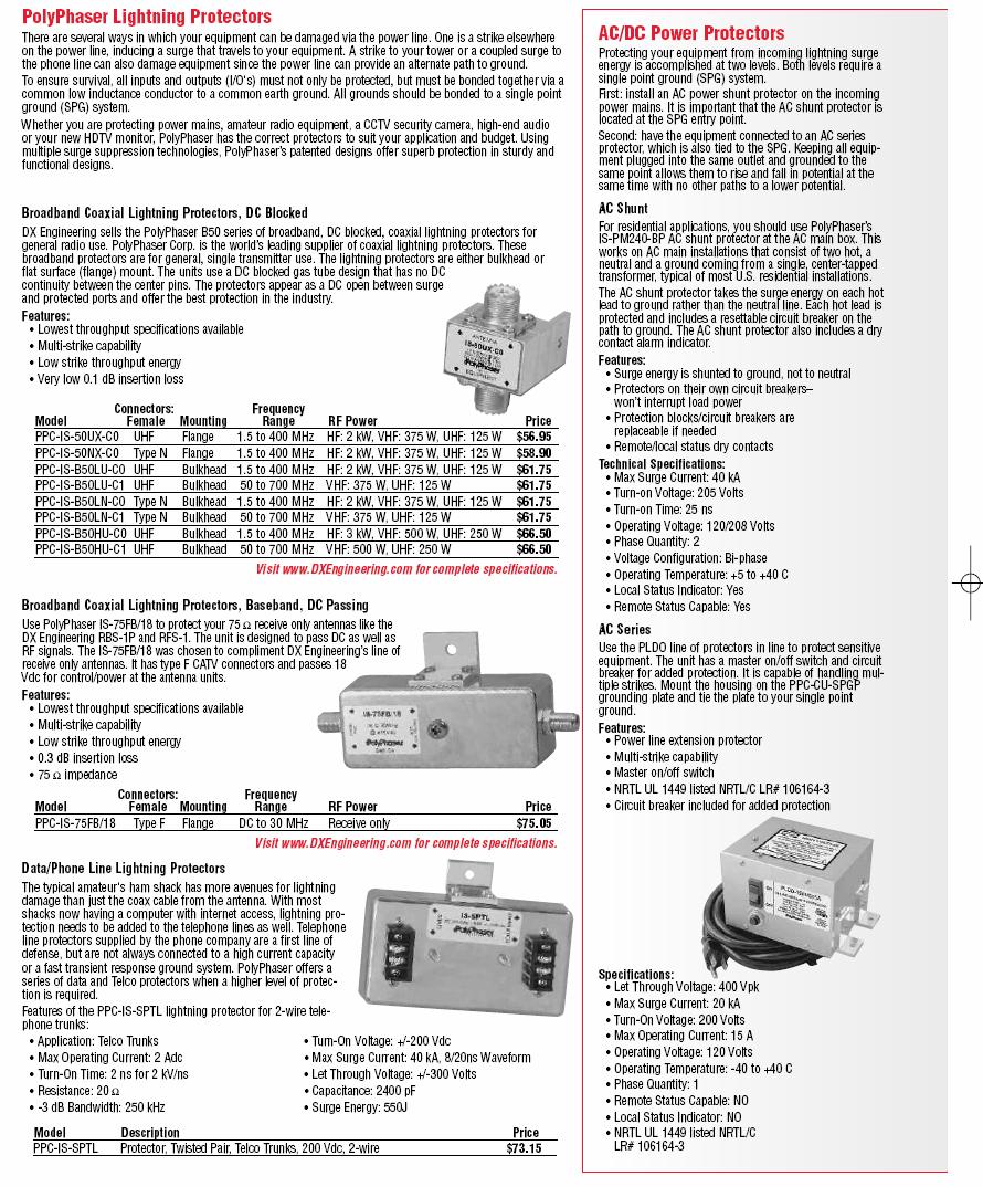
2 Outdoor Utility Enclosure The DXE-UE-1P is a weather-resistant, high impact thermoplastic enclosure which is ideal for outdoor mounting of all types of lightning suppressors and other equipment. Its weather-tight design protects the inside components against rain and directed water spray. The thermoplastic housing and wire entrance grommet materials used in the enclosure are fire retardant, UV stabilized and resists degradation from environmental contaminants, chemical fertilizers and insecticide sprays. The housing can be painted with latex or oil base paints. Included with the DXE-UE-1P: Weather-tight 12 ¼" x 12" x 5 ¼" Enclosure Plated #8 x 1 ½ Wood Screws (3) Four plastic mounting plate spacers 8" x 9.5" 6061-T6 Aluminum Mounting Plate with Stainless mounting screws Four weather-tight coax feed through couplers Drilling Template Because this enclosure has many potential applications, no holes have been drilled in the enclosure or the aluminum mounting plate. The drilling template should be used to drill the mounting holes in the aluminum plate to match the corner mounting bosses in the enclosure. Four Stainless self-tapping screws are included to secure the mounting plate to the enclosure. Figure 1: Utility Enclosure shown with Optional Equipment A typical application is shown in Figure 1. Two coaxial lightning suppressors and one telephone line protector are mounted to the aluminum mounting plate. A copper ground strap is bonded to the plate and runs to the Single Point Ground system.

3 Installation The UE-1P can be mounted on exterior walls covered with wood, aluminum or vinyl siding or in the mortar joints of a brick or block wall. Use the three point mounting points with the plated 1 1/2 inch Philips screws. If you are mounting to masonry, install masonry anchors in the mortar joints and use the appropriate screws. Toggle bolts or other specialty anchors may be needed depending on the mounting surface. If necessary, the enclosure can be mounted on a pipe or post with strap clamps. DX Engineering has Stainless clamps in a variety of sizes. See Figure 2. Because of the wide variety of applications and configurations, it would be prudent to layout the equipment that will be mounted on the aluminum plate before final mounting of the enclosure. The template on the last page indicates the location of unused mounting piers in the enclosure that may interfere with equipment mounting. These are noted by circles with gray shading with an X through them. Three Point Enclosure Mounting for Flat Surfaces Aluminum Plate Mounting Posts (Plastic Spacers fit Over These) Figure 2: Enclosure Mounting Options Preparing the Aluminum Mounting Plate Place the plate on a flat surface. Lay the template on the plate. Using a center punch, carefully mark the center of the corner mounting posts as indicated by the circle with the + inside. Note: The holes are not symmetrical. Once drilled, the plate will only mount in the enclosure one way. Drill four 5/32 inch size holes to accommodate the Stainless self tapping screws. Do a trial-fit with the plate in the enclosure before drilling the mounting holes for the suppressors. Take the four plastic spacers, place them over each corner mounting post, lay the plate down on top of the spacers, align the screws and tighten them to 20 in/lbs maximum. You might want to mark the plate to indicate the proper orientation. This will ensure whatever you mount on the plate will fit once the plate is re-mounted in the enclosure.

4 Remove the plate from the enclosure and lay it on a flat surface. Position the suppressors on the plate where they will be mounted. The coax will come into the bottom of the enclosure, through the builtin gasket, to the antenna side of the suppressor. The equipment side coax will run from the suppressor out the top of the enclosure, through the water-tight couplers. In Figure 1, note the alignment of the coax, suppressors and access holes are in a fairly straight line. Some types of coax are not very flexible and sharp bends should be avoided. Mark the location of the suppressor mounting holes using a sharp felt tip marker. You can draw an outline of the suppressor on the plate to help locate it after drilling. A 3/16 inch drill bit makes the correct size hole to mount most PolyPhaser suppressors. Note: Before mounting any suppressor, clean the aluminum plate and the mounting tab on the suppressor. The PolyPhaser Copper Cleaning kit (part number PPC-CCK) is highly recommended. It includes cleaning pads and copper joint compound which should be used between the suppressor mounting tab and the plate. This will assure a long-lasting corrosion-free joint. You could also use Penetrox A. (part number DXE-P8A) Do not use star or other washers between the suppressor and the plate. If you use the coax weather-tight couplers, use a 7/8 inch hole saw, available at most home supply stores, to make the proper size hole in the enclosure. Check the hole alignment with the bottom access holes to make sure the coax or wiring will run in a straight line from bottom to top. The center of the coupler mounting hole should be 1-3/16 inches below the edge of the enclosure with the lid open to avoid interference with the mounting plate or the cover when it is closed. See Figure 3. Insert the coax or other wiring through the top couplers and bottom gaskets before installing connectors. Figure 3: Coax Coupler Drilling Dimension If you intend to use a copper strap to bond the aluminum plate to your Single Point Ground as shown in Figure 1, a bonding strap can be fashioned from a piece of copper bar or heavy strap, available from most home supply stores. Cut the bar or strap wide enough so the mounting holes are on either side of the strap. Drill the appropriate mounting holes in the plate. You can use self-tapping screws to hold the clamp and strap to the plate. You must clean the surfaces and use copper joint compound or Penetrox A between the copper and the aluminum to ensure a long lasting, quality bond between the two dissimilar metals. A slot for the copper strap to go through the enclosure could be made on the bottom, in the plain space between the larger and smaller pre-made openings.
5
6
7 Technical Support If you have questions about this product, or if you experience difficulties during the installation, contact DX Engineering at (330) You can also us at For best service, please take a few minutes to review this manual before you call. Warranty All products manufactured by DX Engineering are warranted to be free from defects in material and workmanship for a period of one (1) year from date of shipment. DX Engineering s sole obligation under these warranties shall be to issue credit, repair or replace any item or part thereof which is proved to be other than as warranted; no allowance shall be made for any labor charges of Buyer for replacement of parts, adjustment or repairs, or any other work, unless such charges are authorized in advance by DX Engineering. If DX Engineering s products are claimed to be defective in material or workmanship, DX Engineering shall, upon prompt notice thereof, issue shipping instructions for return to DX Engineering (transportation-charges prepaid by Buyer). Every such claim for breach of these warranties shall be deemed to be waived by Buyer unless made in writing. The above warranties shall not extend to any products or parts thereof which have been subjected to any misuse or neglect, damaged by accident, rendered defective by reason of improper installation, damaged from severe weather including floods, or abnormal environmental conditions such as prolonged exposure to corrosives or power surges, or by the performance of repairs or alterations outside of our plant, and shall not apply to any goods or parts thereof furnished by Buyer or acquired from others at Buyer s specifications. In addition, DX Engineering s warranties do not extend to other equipment and parts manufactured by others except to the extent of the original manufacturer s warranty to DX Engineering. The obligations under the foregoing warranties are limited to the precise terms thereof. These warranties provide exclusive remedies, expressly in lieu of all other remedies including claims for special or consequential damages. SELLER NEITHER MAKES NOR ASSUMES ANY OTHER WARRANTY WHATSOEVER, WHETHER EXPRESS, STATUTORY, OR IMPLIED, INCLUDING WARRANTIES OF MERCHANTABILITY AND FITNESS, AND NO PERSON IS AUTHORIZED TO ASSUME FOR DX ENGINEERING ANY OBLIGATION OR LIABILITY NOT STRICTLY IN ACCORDANCE WITH THE FOREGOING. DX Engineering 2006 DX Engineering, DXE, Hot Rodz, Maxi-Core, Antenna Designer, Yagi Mechanical, and Gorilla Grip Stainless Steel Boom Clamps, are trademarks of PDS Electronics, Inc. No license to use or reproduce any of these trademarks or other trademarks is given or implied. All other brands and product names are the trademarks of their respective owners.
8 Avoid Drilling in Circles with This Mark (Indicates locations of standoffs) Mark and Drill 5/32 Holes Mark and Drill 5/32 Holes Aluminum Plate Drilling Template. Cut-out along line and tape to plate.
Grounding and Utility Enclosure
 Grounding and Utility Enclosure DXE-UE-2P DXE-UE-2P-INS Rev 1f DX Engineering 2017 1200 Southeast Ave. - Tallmadge, OH 44278 USA Phone: (800) 777-0703 Tech Support and International: (330) 572-3200 Fax:
60 Meter Mono-Band Conversion Kit for the DXE-MBVE-5A Multi-Band Vertical Antenna
 60 Meter Mono-Band Conversion Kit for the DXE-MBVE-5A Multi-Band Vertical Antenna DXE-MBVE-5A60MCK DXE-MBVE-5A60MCK-INS Revision 0a DX Engineering 2017 1200 Southeast Ave. - Tallmadge, OH 44278 USA Phone:
DXE-NCCFL Receive Filter Sets
 DXE-NCCFL Receive Filter Sets The advanced plug-in filter modules (DXE-NCCFL Series) offer frequency-specific receive system enhancements for the DXE- NCC-1 Receive Antenna Phasing Controller. All filter
Two Element Phased Vertical Array System
 Two Element Phased Vertical Array System COM-PVS-160/80/40/30/20 COM-PVS-2-INS-Revision 7 COMTEK SYSTEMS 2011 P.O. Box 1491 - Akron, OH 44309-1491 USA Phone: (800) 777-0703 Technical Support and International:
RX Share Audio Switch
 RX Share Audio Switch DXE-RXSHARE DXE-RXSHARE-INS Revision 0 DX Engineering 2018 1200 Southeast Ave. - Tallmadge, OH 44278 USA Phone: (800) 777-0703 Tech Support and International: (330) 572-3200 Fax:
40 Meter Vertical Antenna
 40 Meter Vertical Antenna COM-40VA COM-40VA-INS-Revision 1 COMTEK SYSTEMS 2016 1200 Southeast Ave. - Tallmadge, OH 44278 USA Phone: (800) 777-0703 Technical Support and International: (330) 572-3200 Fax:
BN-86 Upgrade Balun for Yagi Antennas
 BN-86 Upgrade Balun for Yagi Antennas DXE-BN86-UPG-15T, 15B, 20T and 20B DXE-BN86-UPG-INS Revision 0b DX Engineering 2017 1200 Southeast Ave. - Tallmadge, OH 44278 USA Phone: (800) 777-0703 Tech Support
Balun Upgrade for the DXE-3X10 Skyhawk Antenna or DXE-2X7 Skylark Antenna
 Balun Upgrade for the DXE-3X10 Skyhawk Antenna or DXE-2X7 Skylark Antenna DXE-BAL-YAGI-UPG DXE-BAL-YAGI-UPG-INS Revision 0d DX Engineering 2017 1200 Southeast Ave. - Tallmadge, OH 44278 USA Phone: (800)
Hot Rodz Adjustable Capacity Hat
 Hot Rodz Adjustable Capacity Hat DXE-HR-1P DXE-HR-1P-INS Revision 1b US Patent # 7,002,525 Shown installed on an optional Hustler resonator DX Engineering 2012 P.O. Box 1491 Akron, OH 44309-1491 USA Phone:
RPA-2 HF Modular Receive Preamplifier
 RPA-2 HF Modular Receive Preamplifier DXE-RPA-2 DXE-RPA-2-INS Rev 0 U.S. Patent No. 7,319,435 DX Engineering 2017 1200 Southeast Ave. - Tallmadge, OH 44278 USA Phone: (800) 777-0703 Tech Support and International:
Vertical Antenna Matching Network
 Vertical Antenna Matching Network for the Hustler 5-BTV, 6-BTV and other Quarter Wave Monoband Vertical Antenna Systems DXE-VMN-1 DXE-VMN-1-INS Revision 1d DX Engineering 2017 1200 Southeast Ave. - Tallmadge,
Selecting and Installing Lightning Protection Devices
 Selecting and Installing Lightning Protection Devices A Whitepaper Revision 0 DXE-UE-1P Shown with Optional Equipment Mounted DX Engineering 2006 P.O. Box 1491 Akron, OH 44309-1491 Phone: (800) 777-0703
RPA-1 Preamplifier User Manual
 Page 12 RPA-1 Preamplifier User Manual DXE-RPA-1-INS-Revision 0 PATENT PENDING DX Engineering 2004 P.O. Box 1491 Akron, OH 44309-1491 Phone: (800) 777-0703 Tech Support and International: (330) 572-3200
RPA-2 HF Modular Receive Preamplifier
 RPA-2 HF Modular Receive Preamplifier DXE-RPA-2 DXE-RPA-2-INS Rev 1 U.S. Patent No. 7,319,435 DX Engineering 2018 1200 Southeast Ave. - Tallmadge, OH 44278 USA Phone: (800) 777-0703 Tech Support and International:
Radial Plate DXE-RADP-3. Installation Guide. DXE-RADP-3-INS-Rev 0a Patented
 Radial Plate DXE-RADP-3 Installation Guide DXE-RADP-3-INS-Rev 0a Patented DX Engineering 2012 P.O. Box 1491 Akron, OH 44309-1491 USA Phone: (800) 777-0703 Tech Support and International: (330) 572-3200
HMS Hairpin Matching Systems
 HMS Hairpin Matching Systems DXE-HMS-1P, DXE-HMS-2P, DXE-HMS-4P DXE-HMS-INS-Rev 1h For Use with 1-1/4 Inch through 3 Inch Booms Shown with optional Boom, Elements and Element Bracket with Gorilla Grip
00108/00110 INSTRUCTION MANUAL
 00108/00110 INSTRUCTION MANUAL Removable and Adjustable Mudflap System IMPORTANT! Please Read this Instruction Booklet prior to assembly of your Rock Tamer Kit. IMPORTANT! Exhaust Systems Note: Any modifications
TW Antennas Mono and Multi-Band Vertical Dipole Antenna Systems
 TW Antennas Mono and Multi-Band Vertical Dipole Antenna Systems DXE-TW Series DXE-TW-SERIES-INS Revision 0c DX Engineering 2017 1200 Southeast Ave. - Tallmadge, OH 44278 USA Phone: (800) 777-0703 Tech
The Heritage Pergola
 Eye Level Corporation One Trefoil Drive Trumbull, CT 06611 USA Phone: 888.782.1760 Fax: 888.782.1761 www.@eyelevelliving.com The Heritage Pergola Installation Instructions ARBORS COLUMNS HOSE REELS MAILBOX
PATRIOT DOCKS ASSEMBLY INSTRUCTIONS
 6/1/2008 PATRIOT DOCKS ASSEMBLY INSTRUCTIONS Congratulations on your new Patriot Dock purchase. This manual contains instructions to assemble basic dock configurations for use at typical shoreline application.
One Shelf, Wall Mounted A/V Component Stand Installation Guide Model: EX101SS
 One Shelf, Wall Mounted A/V Component Stand Installation Guide Model: EX0SS For technical assistance or troubleshooting please call -855-994-3832. This product is intended for use only with Audio/Video
Safety Awareness Barriers
 INSTALLATION INSTRUCTIONS FOR These safety awareness barriers are ideal for use in the manufacturing industry to provide a physical and visual means to warn people that hazards exist beyond the barrier.
AM95 Installation Guide
 1321 S. State College Blvd., Fullerton, CA 92831 USA Included Components: Maximum Flat Panel Weight: 95 lb. / 43.1 kg. M4 X 25mm M5 X 25mm M6 X 12mm (Qty 2) M6 X 25mm M8 X 25mm Allen Key Plastic Cover
AM500-U Installation Guide
 1321 S. State College Blvd., Fullerton, CA 92831 USA Included Components Maximum Flat Panel Weight: 500 lb. / 226.79 kg. Wall Mount Bracket (Qty 2) Cross Bar 5/16 Flat Washers (Qty 6) Universal Spacers
Assembly & Installation Instructions
 Wall Mount Garden Hose Reel Model 1041 Assembly & Installation Instructions 1 2 3 4 5 6 8 9 10 12 15 7 11 10 16 17 13 14 CONTENTS QUESTIONS? PROBLEMS? Please DO NOT contact or return this item to the retailer.
Radial Plate DXE-RADP-3. Installation Guide. DXE-RADP-3-INS-Rev 1a U.S. Patent Nos. 6,927,740 and D533,167
 Radial Plate DXE-RADP-3 Installation Guide DXE-RADP-3-INS-Rev 1a U.S. Patent Nos. 6,927,740 and D533,167 DX Engineering 2015 1200 Southeast Ave. - Tallmadge, OH 44278 USA Phone: (800) 777-0703 Tech Support
GB-AVSTOR5 Ceiling Equipment Storage Box with Pipe Coupler
 Ceiling Equipment Storage Box with Pipe Coupler INSTALLATION INSTRUCTIONS CREATING POSITIVE CUSTOMER EXPERIENCES 9534-500-021-00 Contents Weight Limit... 2 Warning Statements... 2 Installation Tools...
Install Instructions. NewAge Steel Welded Tall Locker
 Kit Contains Full Width Adjustable Steel Shelves (4) Height-Adjustable Steel Leveling Legs (4) Aluminum Door Trim (2) 2.5 x ¼ Cabinet Mounting Lag Bolts (4) Large Zinc Plated Mounting Washers (4) 5/8 x
Tilting & Swiveling Flat Panel Wall Mount Installation Guide Model: AXS2040
 Tilting & Swiveling Flat Panel Wall Mount Installation Guide Model: AXS2040 20-40 66 lbs. Supports VESA sizes up to: 200x200 For technical assistance or troubleshooting please call 1-855-994-2825 or visit
2.0. Select Rail & Stair Kit Assembly and Installation Instructions BOM V2 5/13. Owner's Manual. Version
 Select Rail & Stair Kit Assembly and Installation Instructions PLEASE READ OWNER'S MANUAL COMPLETELY BEFORE ASSEMBLING YOUR RAIL OR STAIR KIT. 34106886BOM V2 5/13 Models 73012418 / 73012436 / 73012424
FENCE INSTALLATION GUIDE 8 HIGH WALLS
 FENCE INSTALLATION GUIDE 8 HIGH WALLS 1.866.648.9336 www.simtekfence.com INSTALLATION GUIDE These instructions are designed to assist both professional installers and do-it-yourselfers of SimTek decorative
Page 1 of 18. SunRail System Installation Instructions
 Page 1 of 18 SunRail System Installation Instructions Page 2 of 18 SunRail Stainless Steel Railing Installation Guide Table of Contents Before You Begin 3 Installing Surface Mount Bases for a Two Rail
Models 2130 and 2140
 Models 2130 and 2140 Overview... 2 Tools Needed... 2 Hardware... 2 Assembly... 3-10 Installation...11 Operation... 11 Maintenance... 12 Accessories...12 Limited Warranty... 12 Printed in USA 2007 Perform
INSTALLATION INSTRUCTIONS
 INSTALLATION INSTRUCTIONS SELF LEVELING RADAR ANTENNA MOUNT MODEL 400G QUESTUS MARINE, INC. PO BOX 9 MARBLEHEAD, MA 01945 1-800-RADAR66 TEL 781.639.1900 FAX 781.639.1905 www.questusmarine.com INSTALLATION
Models 2130 and 2140
 Models 2130 and 2140 Overview... 2 Tools Needed... 2 Hardware... 2 Assembly... 3-10 Installation...11 Operation... 11 Maintenance... 12 Accessories...12 Limited Warranty... 12 Perform the following sequence
Tilting, Swiveling & Rotating Flat Panel Wall Mount
 Tilting, Swiveling & Rotating Flat Panel Wall Mount Model: VXA980TC +5 to -5 +5 to -5 Supports most 0-80 Flat Panel TVs Maximum Weight Capacity: 32 lbs. Supports VESA Sizes up to 600x500 For technical
Instruction Sheet D-CPU. Secure CPU Holder
 Instruction Sheet D-CPU Secure CPU Holder I-00457 Rev A PARTS LIST NOTE: Select Security Components when a more secure application is desired. Mounting Track with Mounting Tape Security Bracket Assembly
INSTALLATION MANUAL SONANCE SOUNDBARS SB46 M AND SB46 L. Introduction. Box Contents. Wall Mount Installations
 INSTALLATION MANUAL SONANCE SOUNDBARS SB46 M AND SB46 L Introduction Thank you for purchasing the Sonance Soundbar SB46 M or SB46 L. When properly installed your new Soundbar will give you years of entertainment
Ready-To-Assemble VersaRail INSTALLATION INSTRUCTIONS
 Ready-To-Assemble VersaRail INSTALLATION INSTRUCTIONS Read all instructions prior to installing product. Refer to manufacturers safety instructions when operating any tools. To register your product, please
Installation Instructions Free-Standing Pergola
 Outdoor Distinctions 303 W. Carmel Drive Carmel, IN 46032 844.345.2424 www.outdoordistinctions.com Free-Standing Pergola Harmony Series (14 x 10, 14 x 12, 14 x 14, 14 x 16, 14 x 18, 14 x 20) 1 (14 x 10,
CUTTING THE PIPE: BLUE DUCT Pipe can be easily cut using a Circular Saw or Reciprocal Saw. Trim all edges as necessary.
 Installation Instructions In the past it has been IMPOSSIBLE to install an air and water tight underground system. BLUE DUCT (AKDUCT ) has produced a user friendly system that will reduce the amount of
INSTALLATION INSTRUCTIONS FOR BALCO, INC. NBR SERIES EXPANSION JOINT COVER SYSTEMS
 2626 South Sheridan PO Box 17249 Wichita, Kansas 67217 Phone: (316) 945-9328 Fax: (316) 945-0789 INSTALLATION INSTRUCTIONS FOR BALCO, INC. NBR SERIES EXPANSION JOINT COVER SYSTEMS 2010, Balco, Inc. 09/14/10
Models 2030 and 2040
 Models 2030 and 2040 Overview... 2 Tools Needed... 2 Hardware... 2 Assembly... 3-8 Installation... 9 Operation... 9 Maintenance... 10 Accessories... 10 Limited Warranty... 10 Document # 101290 0607 Printed
Sea Doo Spark Engine Access Kit
 Sea Doo Spark Engine Access Kit PART# - RS4-130-EAK APPLICATION(S): Sea Doo Spark. 2up & 3up Models. We strongly recommend the use of a service manual to familiarize yourself with the various components
Models 2230 and 2240
 Models 2230 and 2240 Overview... 2 Tools Needed... 2 Hardware...3 Assembly... 4-13 Installation... 14 Drawer Removal... 15 Operation... 15 Maintenance... 15 Accessories... 16 Limited Warranty... 16 Perform
Worktop. Weight Capacity. 100 lbs. 21 Corner Worktop. 48 Worktop. Fits over 2 Cabinets. 72 Worktop. Fits over 3 Cabinets. 200 lbs. 150 lbs.
 Bold.0 Warning: Excessive weight hazard! Use two or more people to move, assemble or install cabinets and locker to avoid back injury. Do not leave children unattended near cabinets. High risk of tipping
Single Arm Pole Mount. Installation Manual Edition v1.01. For models: UNI-SA/14 UNI-SA/21.5 UNI-SA/26 UNI-SA01-MAN
 Pole Mount Installation Manual 2016 Edition v1.01 For models: UNI-SA/14 UNI-SA/21.5 UNI-SA/26 UNI-SA01-MAN Table of Contents 1 1 2 3 4 5 5 Introduction Customer Support Project Essentials Assembly: Steps
ATTENTION: PLEASE READ AND UNDERSTAND ALL INSTRUCTIONS AND WARNINGS BEFORE ASSEMBLING, INSTALLING OR USING THIS PRODUCT.
 INSTALLATION MANUAL Models 96111-3-02 & 96511-3-02 Bulkheads for 2014 and Later Ford Transit Connect Vans ATTENTION: PLEASE READ AND UNDERSTAND ALL INSTRUCTIONS AND WARNINGS BEFORE ASSEMBLING, INSTALLING
K1FO 12 ELEMENT 144/147 MHz YAGI
 K1FO 12 ELEMENT 144/147 MHz YAGI WARNING: INSTALLATION OF THIS PRODUCT NEAR POWER LINES IS DANGEROUS. FOR YOUR SAFETY FOLLOW THE INSTALLATION DIRECTIONS. Ariane Arrays, Inc. Copyright 2006 201 Hopedale
LJ element beam for 10 or 12 meters INSTRUCTION MANUAL. CAUTION: Read All Instructions Before Operating Equipment
 LJ-113 3 element beam for 10 or 1 meters INSTRUCTION MANUAL CAUTION: Read All Instructions Before Operating Equipment 308 Industrial Park Road Starkville, MS 39759 USA Tel: 66-33-9538 Fax: 66-33-6551 VERSION
( ) CanPRO. Recommended Handle Turns: Can Size Diameter Handle Turns #2 3" 3 Revolutions #5 5" 5 Revolutions #10 6" 6 Revolutions.
 CanPRO. Recommended Handle Turns: Can Size Diameter Handle Turns #2 3 3 Revolutions #5 5 5 Revolutions #10 6 6 Revolutions.") 56050 - ( ) CanPRO OPERATING INSTRUCTIONS Important 1. To get the best operation and life from your machine, please read and comply with these instructions. 2. Clean machine thoroughly before and after
56050 - ( ) CanPRO OPERATING INSTRUCTIONS Important 1. To get the best operation and life from your machine, please read and comply with these instructions. 2. Clean machine thoroughly before and after
INSTALL INSTRUCTIONS WELCOME TO THE NEWAGE PERFORMANCE CABINETRY SERIES NEWAGE STEEL WELDED CABINETRY
 NEWAGE STEEL WELDED CABINETRY WELCOME TO THE NEWAGE PERFORMANCE CABINETRY SERIES ALL CABINETS MUST BE MOUNTED TO STUDS ON A SECURE WALL, AS PER THESE INSTRUCTIONS. FAILURE TO DO SO MAY RESULT IN SERIOUS
Installation Instructions Hustler Collinear Two Meter Fixed Station Antenna Master Gainer Model G6-144B
 Installation Instructions Hustler Collinear Two Meter Fixed Station Antenna Master Gainer Model Warning INSTALLATION OF THIS PRODUCT NEAR POWER LINES IS DANGEROUS. FOR YOUR SAFETY, FOLLOW THE INSTALLATION
Installation Instructions SRC OFF ROAD ROOF RACK Wrangler,97-06 Wrangler,04-06 Unlimited Part # s 76711,76713,76715)
") NOTE: Please read this information entirely before installing. To obtain correct installation, we recommend you follow these step-by-step instructions carefully. Please take care when installing this product
NOTE: Please read this information entirely before installing. To obtain correct installation, we recommend you follow these step-by-step instructions carefully. Please take care when installing this product
A Practical NVIS Antenna for Emergency or Temporary Communications
 A Practical NVIS Antenna for Emergency or Temporary Communications Rev. 0 Optimum for 40 and 80 Meters DX Engineering 2008 P.O. Box 1491 Akron, OH 44309-1491 Phone: (800) 777-0703 Tech Support and International:
Owner s Manual LSP38 38 Lawn Sweeper
 Owner s Manual LSP38 38 Lawn Sweeper Manual Contents Safety Instructions Assembly Operation Maintenance Parts Warranty 2 4-13 2 11 14-15 16 Your Lawn Sweeper Congratulations on your purchase of a new Precision
EMERGENCY CALL AMBULANCE
 2nd PRINTING DEC 99 EMERGENCY CALL AMBULANCE KIT VERSION (ROM SET) OWNER S MANUAL SEGA ENTERPRISES, INC. USA MANUAL NO. 999-0858 Warranty Your new Sega Product is covered for a period of 90 days from the
Tilting Flat Panel Wall Mount Installation Guide
 Tilting Flat Panel Wall Mount Installation Guide Model: A580TM Easy installation Built-in level for easy positioning Safety bolts lock the TV on the mount Easy to adjust tilt angles: +5 to -15 degrees
INSTALLATION INSTRUCTIONS
 CREATING POSITIVE CUSTOMER EXPERIENCES INSTALLATION INSTRUCTIONS Universal Low Profile Tilt Mount for 42 to 63 Flat Panels NORTH AMERICA 3130 East Miraloma Avenue Anaheim, CA 92806 USA USA and Canada Phone:
ANTENNA SYSTEMS. PTX Offset Antenna.60/.76/.90./1.1m INSTALLATION & ASSEMBLY INSTRUCTIONS
 ANTENNA SYSTEMS PTX Offset Antenna.60/.76/.90./1.1m INSTALLATION & ASSEMBLY INSTRUCTIONS LIMITED TWELVE (12) MONTH WARRANTY This PATRIOT ANTENNA equipment is warranted to be free from defects in material
340 & 350 SERIES DELUXE FRAMELESS BYPASS
 BATH ENCLOSURES An Alcoa Company Tel: 800-643-1514 Fax: 870-234-3181 www.alumaxbath.com INSTALLATION INSTRUCTIONS 340 & 350 SERIES DELUXE FRAMELESS BYPASS BATH ENCLOSURES Copyright Alumax Bath Enclosures
Installation Instructions. Tools Needed. Tape measure. Level. Shovel or Post hole digger. Concrete. Drill. Stakes. Mallet or hammer.
 Installation Guide EcoStone Fence 1330 West 400 North Orem, UT 84057 Toll Free 1.866.648.9336 Tel. 1.801.655.5236 Fax 1.801.655.5240 www.ecostonefence.com Installation Instructions Introduction. These
Installation and Assembly: Articulating Swivel Arm for 37" - 60" Flat Panel Displays
 Installation and Assembly: Articulating Swivel Arm for 37" - 60" Flat Panel Displays Models: PLA60, PLA60-S, PLAV60, PLAV60-S Max UL Load Capacity: 175 lb (79 kg) 2300 White Oak Circle Aurora, Il 60502
Balishutters. INSTALLATION guide FOR L-FRAME MOUNT INSTALL OPTIONS B OR C
 Balishutters INSTALLATION guide FOR L-FRAME MOUNT INSTALL OPTIONS B OR C Tools needed for installation Drill Phillips bit 1/8" drill bit 4. Hammer (preferably hard plastic) 5. Level 6. Phillips-head screwdriver
Installation and Assembly: Recessed Cable Management and Power Storage Accessory Box
 Installation and Assembly: Recessed Cable Management and Power Storage Accessory Box Models: IBA2AC, IBA2AC-W 2300 White Oak Circle Aurora, Il 60502 (800) 865-2112 Fax: (800) 359-6500 www.peerlessmounts.com
INSTALLATION INSTRUCTIONS
 INSTALLATION INSTRUCTIONS P4263F Universal Low Profi le Flat Mount for 42 to 63 Flat Panels NORTH AMERICA 3130 East Miraloma Avenue Anaheim, CA 92806 USA USA and Canada Phone: 1.800.368.9700 Fax: 1.800.832.4888
QuadroMAX. Installation Manual. QM Series. LED Outdoor Lighting Fixtures REV: 3/22/16
 QuadroMAX LED Outdoor Lighting Fixtures Installation Manual QM Series REV: 3/22/16 BEFORE YOU BEGIN Read these instructions completely and carefully. WARNING Risk of fire or electric shock. Luminaire wiring
TENNADYNE TD-160HP800
 TENNADYNE Aluminum with a PhD ASSEMBLY INSTRUCTIONS TD-160HP800 SPECIFICATIONS: Impedance: 50 Ohm nominal Bandwidth :1.8-30 MHz Length : 160 ft. Power : 8 KW Impulse 2400 W PEP SSB 800 W AM/FM/RTTY Connector
One Revolution Tube Cutter
 One Revolution Tube Cutter Series 9060 Tube & Pipe Cleaners Tube Testers Tube Plugs Tube Removal Tube Installation Operating and Maintenance Instructions www.elliott-tool.com Table Of Contents Introduction...
340 & 350 SERIES BATH ENCLOSURES
 INSTALLATION INSTRUCTIONS 340 & 350 SERIES BATH ENCLOSURES 800-643-1514 www.alumaxbath.com Copyright Alumax Bath Enclosures 2010. All rights reserved. LIMITED WARRANTY AND REMEDY ALUMAX BATH ENCLOSURES
FENCE INSTALLATION GUIDE 6 HIGH FENCE
 FENCE INSTALLATION GUIDE 6 HIGH FENCE 1.866.648.9336 www.simtekfence.com INSTALLATION GUIDE These instructions are designed to assist both professional installers and do-it-yourselfers of SimTek decorative
Installation Instructions:
 NOTE: Carefully read entire instructions thoroughly before attempting to install this part. (SB76904) Parts Included Qty 94-241CA001 Front Upright: Drvr 1 94-241CA002 Front Upright: Pass 1 94-241CA003
LC6X4WTM Security Wall Mount with Tilt for up to 60" Flat Screens with VESA 600mm x 400mm or less
 Page 1 of 6 The LC6X4WTM Security Wall Mount with Tilt is designed to secure a flat screen, up to a 60", to the wall while still allowing the monitor to tilt. The VESA mounting patterns on the front of
The MFJ-1754 can be mounted on any 1" to 1 1/2" mast (conductive or non conductive.)
") INTRODUCTION: The MFJ-1754 is designed for use on the 2 meter and the 70 centimeter bands. On the 2 meter band the MFJ-1754 behaves as a vertical 1/4 wave antenna, however on 70 centimeter band the MFJ-1754
INTRODUCTION: The MFJ-1754 is designed for use on the 2 meter and the 70 centimeter bands. On the 2 meter band the MFJ-1754 behaves as a vertical 1/4 wave antenna, however on 70 centimeter band the MFJ-1754
Series 500. Owner s Manual. Analog Transmitters by Data Industrial. Data Industrial. Data Industrial 2/95 PN 72806
 Series 500 Analog Transmitters by Data Industrial Data Industrial Owner s Manual Data Industrial 2/95 PN 72806 Table of Contents Introduction... 1 4-20 ma Loop Supply Requirements... 2 Installation...
HUSTLER 7' & 8' POOL TABLE ASSEMBLY INSTRUCTIONS
 HUSTLER 7' & 8' POOL TABLE ASSEMBLY INSTRUCTIONS Please Do Not Hesitate to Contact Our Consumer Hotline at 800-759-0977 with Any Questions That May Arise During Assembly or Use of This Product! NG2515PB/NG2520PB
Spa & Hot Tub Necessities. Cover Removal System Installation & Use Manual
 Spa & Hot Tub Necessities Cover Removal System Installation & Use Manual SET-UP AND ASSEMBLY BEFORE BEGINNING ASSEMBLY, CAREFULLY READ THE FOLLOWING INFORMATION AND INSTRUCTIONS: Place all parts in a cleared
TENNADYNE. Aluminum with a PhD. Tennadyne ASSEMBLY INSTRUCTIONS MODEL: T Log Periodic Antennas SPECIFICATIONS:
 TENNADYNE Aluminum with a PhD ASSEMBLY INSTRUCTIONS MODEL: T10-100224 SPECIFICATIONS: FREQUENCY COVERAGE 13-33 MHz FORWARD GAIN 6.1 dbd ½ POWER BEAMWIDTH 52 DEGREES F:B RATIO To 25 Db (Rises with frequency)
Sonoma Outdoor Kitchen Pergola. Assembly Instructions
 Sonoma Outdoor Kitchen Pergola Assembly Instructions Introduction Thank you for your purchase from The Outdoor GreatRoom Company. This pergola has been engineered and manufactured in the USA. This user
Telescopic Screw Gun Bracket & Accessories
 Telescopic Screw Gun Bracket & Accessories TSGB Features and Benefits: Fast and easy installation Allows attachment from the front or inside of the stud in any depth Improved design with stamped inch markings
Installation Instructions Cage Kit JK Unlimited (4-Dr) Part # 76902
 Part # 76902") Please read instructions entirely before installing this product. Drilling is required to install this part. Parts Included Qty Parts Included Qty Driver Front Upright 1 Pass Side Drill Template (7289)
Please read instructions entirely before installing this product. Drilling is required to install this part. Parts Included Qty Parts Included Qty Driver Front Upright 1 Pass Side Drill Template (7289)
FP-4855 Flat Panel Television Stand ASSEMBLY INSTRUCTIONS
 FP-4855 Flat Panel Television Stand ASSEMBLY INSTRUCTIONS Patent Pending Italian Designed A Product of China Do not discard these instructions M-1_051607v3 Bell O International Corp. will not be responsible
INSTRUCTION MANUAL. Specifications Mechanical. 1 5/8 to 2 1/16 O.D. (41mm to 52mm)
") 308 Industrial Park Road Starkville, MS 39759 USA Ph: (662) 323-9538 FAX: (662) 323- General Description Model VB-25FM 2-Meter 5 Elements Beam INSTRUCTION MANUAL This antenna is a 5-element, 2-meter beam
308 Industrial Park Road Starkville, MS 39759 USA Ph: (662) 323-9538 FAX: (662) 323- General Description Model VB-25FM 2-Meter 5 Elements Beam INSTRUCTION MANUAL This antenna is a 5-element, 2-meter beam
Installation Manual Roof Zone Ladder Rack
 Installation Manual Roof Zone Ladder Rack 102113,E1346 Installation Time: About 90 minutes. Depending on truck and Do-it-Yourself experience level Tools Required: Electric Drill with 1/2 Chuck 1/2 & 7/32
JK-65 Five Element 6M Yagi
 JK-65 Five Element 6M Yagi PO Box 266, Croton Falls, NY 10519-0266 845.228.8700 (TEL) 845.279.5526 (FAX) info@jkantennas.com Page 1 of 8 JK Antennas Limited Warranty and Liability JK Antennas ( Manufacturer
Specifications. Important Safety Information
 Specifications Tire Rim Capacity 4 to 12 Rim Height 16 (2) Bead Breaker Handles 21 Long Includes Aluminum Centering Cone (2) Nylon Spacers Important Safety Information 1. Do not exceed max. tire capacity.
Performance 2.0 Series
 Performance. Series Warning: Excessive weight hazard! Warning: Excessive weight hazard! Use two or more people to move, assemble, or install cabinets and locker to avoid back injury. Do not leave children
BASE & WALL CABINET SETUP GUIDE BY SUNSTONE
 BASE & WALL CABINET SETUP GUIDE BY SUNSTONE Read all instructions before you install cabinet. Very important to follow each step in order as detailed in this Instruction Guide!!! To installer or person
Installation and Operation Manual MSI. Multi-Sensor Interface Hub. Interface Module for all Sensors Network and Wireless CAUTION
 Installation and Operation Manual MSI Multi-Sensor Interface Hub Interface Module for all Sensors Network and Wireless CAUTION This equipment complies with the limits for a Class B digital device, pursuant
SERIES M MIXER MASTS
 SERIES M MIXER MASTS T AB L E O F C O N T E N T S V e n d o r D a t a Material Data Sheet 4-in. Mixer Mast Specification 3-in. Mixer Mast Specification 2 - in. M i x e r M a s t S p e c i f i c a t i o
Need a little help installing your railing?
 Need a little help installing your railing? www.rdirail.com/support/installation-videos.html Post Installation LAG BOLT APPLICATION Determine the desired rail placement and snap a line on to the deck to
SS/SW3230RTA Assembly Instructions Ready to Assemble Multimedia Lectern
 650 Anthony Trail, Suite D, Northbrook, IL 60062 Phone: (800)267-5486 Fax: (800)267-5489 www.ampli.com - info@ampli.com SS/SW3230RTA Assembly Instructions Ready to Assemble Multimedia Lectern Thank you
Owner s Manual GS2010 Garden Seeder/Fertilizer. Caution: Carefully read all Rules and Instructions for Safe Operation.
 Manufacture s Limited Warranty for The limited warranty set forth below is given by Precision Products, Incorporated with respect to new merchandise purchased and used in the United States, its possessions
GENERAL INSTALLATION GUIDE: WARRANTY: PRODUCT INFORMATION T F
 GENERAL INSTALLATION GUIDE: Unless otherwise indicated, all Seven Oaks M.U. Architectural Products materials are to be used for decorative purposes only. All products must be installed using ample amount
9 PIECE TUNGSTEN CARBIDE HOLE SAW KIT. Model 90721
 9 PIECE TUNGSTEN CARBIDE HOLE SAW KIT Model 90721 Set up And Operating Instructions Diagrams within this manual may not be drawn proportionally. Due to continuing improvements, actual product may differ
Series 1600 WeatherGuard Dock Enclosure
 Fairborn USA Inc. 205 Broadview Street Upper Sandusky, OH 43351 1-800-262-1188 Fax 1-419-294-4980 Series 1600 WeatherGuard Dock Enclosure All Models! WARNING Do not install this product unless you read
Black or White Classic Country Chair Item Number Black Chair: BH Item Number White Chair: BH
 ASSEMBLY INSTRUCTIONS Black or White Classic Country Chair Item Number Black Chair: BH10-084-90-1 Item Number White Chair: BH10-084-90-14 CUSTOMER SERVICE INFORMATION If parts are missing, DO NOT return
ASSEMBLY AND INSTALLATION INSTRUCTIONS R , 12, 15, 17, 20, 30, 40 Meters (5/99) COMMUNICATIONS ANTENNAS
 COMMUNICATIONS ANTENNAS") ASSEMBLY AND INSTALLATION INSTRUCTIONS R7000 10, 12, 15, 17, 20, 30, 40 Meters COMMUNICATIONS ANTENNAS 951465 (5/99) WARNING THIS ANTENNA IS AN ELECTRICAL CONDUCTOR. CONTACT WITH POWER LINES CAN RESULT
ASSEMBLY AND INSTALLATION INSTRUCTIONS R7000 10, 12, 15, 17, 20, 30, 40 Meters COMMUNICATIONS ANTENNAS 951465 (5/99) WARNING THIS ANTENNA IS AN ELECTRICAL CONDUCTOR. CONTACT WITH POWER LINES CAN RESULT
Veranda Decorative Lattice & Deck Skirting Special Order Catalog
 Veranda Products. Built by Barrette. Veranda Decorative Lattice & Deck Skirting Special Order Catalog NEW! Designer Series Deck Skirting in 4 styles V1 2/17 1 Your Decorative Lattice Options Choose the
P4263TP. Installation Guide. Low-Profile Tilting Portrait Mount for Flat-Panels
 Low-Profile Tilting Portrait Mount for Flat-Panels 1321 S. State College Blvd., Fullerton, CA 92831 USA Weight Limit Maximum Flat Panel Weight: 175 lbs. Warning Statements THE WALL STRUCTURE MUST BE CAPABLE