Antenna Modelling Software
|
|
|
- Kevin Sparks
- 5 years ago
- Views:
Transcription
1 Antenna Modelling Software What How Programs NEC based Others Program extensions NSARC Tech Topics 1
2 Antenna Modelling 2

3 Mathematical Modelling Original DRAO (Dominion Radio Astrophysical Observatory) Antennas The main goal of the T-shaped radio telescope at Penticton was to produce a map of radio sources in our galaxy. 3

4 Scale models A 10:1 model Eg 300 MHz antenna (1m) on a 30m aircraft Is mainly for initial pattern measurements. For impedances the model scale must be reduced to 4:1 or 2:1. 4
5 Computational Modelling Codes are based on a full-wave formulation of the Maxwell's equations and associated boundary conditions. Some other codes are based on an asymptotic solution of the Maxwell's equations. Finite-Difference Time-Domain method (NEWS, X-NEWS) Finite Element Method (FEM, X-FEM) High Frequency Structure Simulator (HFSS) WirePlate (WIPL) FEKO "FEldberechnung für Körper mit beliebiger Oberfläche" Numerical Electromagnetic Code (NEC) Electromagnetic Surface Patch (ESP) NEWAIR (Geometric theory of diffraction, GTD based) 5
6 Computational Modelling Most codes are based on the Method of Moments (MoM) integral formulation of Maxwell's equations Most Amateur programs break the model into a number of current driven elements and then combine the effect of the fields EG NEC There are limits to free versions Wires cannot meet in the middle of a segment Wire intersection angle limit Wires must be the same diameter (tapers can be fudged ) Wires in close proximity must have their segments matched Other limits 6
7 NEC Developed by Lawrence Livermore Laboratory in 1981 for the US Navy based on the AMP program contracted in 1970 Antenna is divided into short segments with linear variation of current and voltage. Developed in a number of stages NEC2 models in free space or over finitely conducting ground. Free (with a command line interface ) so used in most NEC programs. NEC4.2 smaller structures, accurate stepped radius and junctions, improved ground modelling (buried conductors). Requires $US500 license. 7
8 EZNEC Available in a number of variations Demo 20 segments (ARRL version 500) Free EZNEC 500 segments $US99 EZNEC segments $US149 EZNECpro 20,000 segments $US525 EZNECpro/4 $US675 (NEC4 engine) License must be approved $US500 for noncommercial use. 8
9 AutoEz An add-on for EZNEC allowing you to parameterize the program by using variables to control aspects of the module. Excel taken to the limit! Simplified data input Improved results presentation Free demo (30 segments or EZNEC limit) Full version $US79 9
10 4NEC2 Free Two programs 4NEC2 (basic NEC 2 engine but supports NEC4) 4NEC2X (Extended) 3D presentation Includes and optimizer and sweeper Improved input and output compared to EZNEC 10
11 MiniNEC $US29 c-antenna-analysis-modeling-software.html This is an improved version of that released by NTIS based on the NEC2 engine. This is a 1991 review of MiniNEC by Roy Lewallen (the author of EZNEC) pdf 11
12 MMANA-GAL Free in basic form 8192 Segments Similar to EZNEC Pro version available for ,000 segments Improved graphics 12
13 ASAP Free (NEC2 based) Basic interface to NEC2 13
14 So What to use? Program Cost Limit Note EZNEC $US99 Free versions too restrictive Most common AutoEZ $US79 optimizer, Same segments as associated EZNEC Requires EZNEC Improves in/out 4NEC2 Free Same as NEC engine Roughly ~= EZNEC+AutoEZ NEC Free 2000 segments No user interfaces NEC4-2 $US500 20,000 segments Use with 4NEC2 MININEC $US segments? Also free basic MMANA-GAL free 8192 segments Pro 139 ASAP Free 2000 segments? Basic interface There are many more programs available 14
15 An Example 40m vertical with two raised radials Vary base between -0 to 20 ft Special cases, buried radials, slanted radials Design antenna (resonance, matching) Determine efficiency Set all losses =0 and compare to measured with losses Compare input and output of programs Show issues 15
16 An Example Compare EzNEC MMNA-GAL similar AutoEZ 4NEC2 NEC Original command line interface Inspired the enhancements More basic enhanced programs MiniNEC, ASAP 16
17 Modelling Steps 1. Sketch the antenna (same for all) 4NEC2 has a graphical input 2. Input Model Wires, segments, Sources and loads 3. Check for problems 4. Run 5. Output results Notes: dimensions 33 chosen to demonstrate optimization Slant to demonstrate model input options 17

18 Sketch Horizontal Radials h= -0.5,0,1,10,20 Slanted Radial (special case 0 to 10 ) 18


19 Input Model (EZNEC) 19
 Uses")

20 Input Model (AutoEZ) Uses Excel tables and variables can be used 20

21 Input Model (AutoEZ) Variables can be used 21


22 Input Model (4NEC2) Several editors including a rudimentary graphics editor. Can use Variables and formulae. Inputs EZNEC files. 22

23 Input Model (NEC) Pure text file 23
24 Check for problems EZNEC EZNEC runs a rules check before giving SWR or field data. Yellow is a warning, Red is an rule violation. Fix Source 1 by adding a short wire Fix wire 2 by adding more segments (auto-segment) 24
25 Check for problems AutoEz Uses EZNEC to check 25


26 Check for problems 4NEC2 Warnings can be cryptic and assume that you know the NEC input file rules 26
27 Check for problems NEC Limited rules checking Limited Help 27


28 Run EZNEC You can select various outputs e.g. SWR, FF plot And get tabular data for use in other programs 28

29 Run AutoEZ Note can vary multiple variables 29


30 Run 4NEC2 A bit confusing as a variety of external programs are called. 30
31 Run NEC Pure command line operation. Limited graphics engine 31
32 Output results EZNEC Can also get tabular data 32

33 Output results AutoEZ Effect of varying multiple variables can be shown 33
34 Output results AutoEZ A number of additional outputs are available 34


35 Output results AutoEZ There is an optimizer 35


36 Output results 4NEC2 There are tabular and graphics outputs 36


37 Output results 4NEC2 There are tabular and graphics outputs 37

38 Output results 4NEC2 There is a multivariable optimizer 38
39 Output results NEC Mainly tabular Limited Graphics 39
40 Comments NEC is an old mainly text based program which has resulted in many improvements EZNEC is most familiar to Amateurs and AutoEZ adds useful features. 4NEC2 has all of the features of EZNEC+ AutoEZ and can use EZNEC files but the work flow is not easy to follow. The 3D graphics are nice and a graphics editor may help some people. ALL programs require an understanding of the limitations of NEC especially NEC2. 40


41 Special Case Gull Wing Radials NEC2 has problems with wires that intersect at an acute angle. NEC4 can handle this. 41


42 Special Case Buried Wires NEC 2 will not calculate wires in the ground but using the NEC 4 engine the length of a buried dipole can be modelled and optimised. 42
43 A Complicated Case VE7SCC Quad 2 el on 30 and 40m 4 el on 20, 17, 15, 12, 10 Models interaction of elements which is complicated. Can add coax matching sections Can model antenna switching Easy to generate model 43

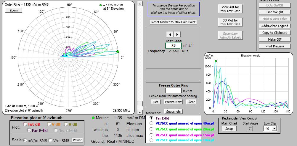
44 A Complicated Case VE7SCC Quad 44

45 A Complicated Case VE7SCC Quad 45
46 Sinclair 440 Beam John White showed this as part of his Yagi presentation NEC 4 should be used to model the cross-overs which are too close for NEC2 but NEC2 works by using the equivalent 2 sources. 46
47 A NEC4 Case Sinclair 440 Beam The matching appears to be dependant upon the interaction of the folded dipoles as otherwise 1/4λ 125ohm coax would be required. This curve was confirmed with an AIM600 but with better SWR. 47
Antenna Modelling with NEC2. Vincent Harrison ZS6BTY
 Antenna Modelling with NEC2 Vincent Harrison ZS6BTY NEC2 NEC - Numerical Electromagnetic Code Lawrence Livermore Laboratory Program Description - 1981 Part 1 Theory Part 2 - Code MiniNEC BASIC IBM PC 2
EZNEC Primer. Introduction:
 EZNEC Primer Introduction: This document was written to cover the very basic functions of EZNEC. It's primarily geared to the use of EZNEC demo programs, specifically the Version 5 demo. While more elaborate
An Introduction to Antenna Analysis and Modeling Part 1: The Basics
 An Introduction to Antenna Analysis and Modeling Part 1: The Basics Najm J. Choueiry, AB1ZA. 01.04.2019 In this introduction to antenna analysis and modeling, I will focus on two well-known software packacges,
ANTENNA DESIGN FOR FREE USING MMANA-GAL SOFTWARE
 ANTENNA DESIGN FOR FREE USING MMANA-GAL SOFTWARE 1. AVAILABLE ANTENNA DESIGN SOFTWARE EZNEC and 4nec2 are based upon the Numerical Electromagnetics Code, or NEC, which is a popular antenna modelling system
Computer Antenna Modeling Simplified KE5KJD
 Compiled from the Internet for the AARA Ham Radio Club - 2010 Computer Antenna Modeling Simplified KE5KJD An exposure to the benefits of computer modeling using software. Antenna Modeling What is it? Computerized
I recently came across a No-Counterpoise antenna described by designed by Peter Millis M3KXZ and based on an original design by K9ESE.
 M3KXZ 'no counterpoise' antenna I recently came across a No-Counterpoise antenna described by designed by Peter Millis M3KXZ and based on an original design by K9ESE. Details of the antenna can be found
Electric and Magnetic Fields Near Physically Large Radiators
 Electric and Magnetic Fields Near Physically Large Radiators 1. Overview Author: Ed Hare, ARRL Laboratory Manager 1 Date: July 7, 2003 1.1 Making measurements of electric and magnetic field strength requires
Feed Line Currents for Neophytes.
 Feed Line Currents for Neophytes. This paper discusses the sources of feed line currents and the methods used to control them. During the course of this paper two sources of feed line currents are discussed:
Beams and Directional Antennas
 Beams and Directional Antennas The Horizontal Dipole Our discussion in this chapter is about the more conventional horizontal dipole and the simplified theory behind dipole based designs. For clarity,
TBARC Programs Antenna Modeling with 4NEC2. By Randy Rogers AD7ZU 2010
 TBARC Programs Antenna Modeling with 4NEC2 By Randy Rogers AD7ZU 2010 Getting Started 4NEC2 is a completely free windows based tool suite to aid in the design and optimization of antenna systems 4NEC2
Antenna Modelling For Radio Amateurs Made Easier -Part 2
 Antenna Modelling For Radio Amateurs Made Easier -Part 2 G8ODE RSARS 1619 Even the simple formula for the quarter wave element hides some daunting complex science and mathematics that most of us are unaware.
Computational Magic and the EMC Engineer
 Computational Magic and the EMC Engineer By Glen Dash, Ampyx LLC, GlenDash at alum.mit.edu Copyright 1999, 2005 Ampyx LLC Using a computer to simulate EMC phenomena is a field full of promise. In decades
NCJ Reviews: MultiNEC 2.0
 NCJ Reviews: MultiNEC 2.0 The most useful program I use for both antenna modeling and propagation prediction is not a program at all. It s also the only shareware for which I eagerly paid the registration
Antenna Simulation Tools and Designing of Log Periodic Dipole Antenna with CST Studio
 Antenna Simulation Tools and Designing of Log Periodic Dipole Antenna with CST Studio Vijay Kale 1, Dnyandev Patil 2 Assistant professor, Department of Electronic Science, KTHM College, Nashik, Maharashtra,
The Fabulous Dipole. Ham Radio s Most Versatile Antenna
 The Fabulous Dipole Ham Radio s Most Versatile Antenna 1 What is a Dipole? Gets its name from its two halves One leg on each side of center Each leg is the same length It s a balanced antenna The voltages
Chapter 1 - Antennas
 EE 483/583/L Antennas for Wireless Communications 1 / 8 1.1 Introduction Chapter 1 - Antennas Definition - That part of a transmitting or receiving system that is designed to radiate or to receive electromagnetic
Antenna Theory and Design
 Antenna Theory and Design SECOND EDITION Warren L. Stutzman Gary A. Thiele WILEY Contents Chapter 1 Antenna Fundamentals and Definitions 1 1.1 Introduction 1 1.2 How Antennas Radiate 4 1.3 Overview of
Loop-Dipole Antenna Modeling using the FEKO code
 Loop-Dipole Antenna Modeling using the FEKO code Wendy L. Lippincott* Thomas Pickard Randy Nichols lippincott@nrl.navy.mil, Naval Research Lab., Code 8122, Wash., DC 237 ABSTRACT A study was done to optimize
2. THE THEORY OF DIPOLE ANTENNAS AND YAGI-
 ACKNOWLEDGMENTS I would like to thank GOD for helping me in finishing this work. GOD you have made my life more bountiful. May your name be exalted, honored, and glorified. I would like to express my gratitude
EZNEC Simulations Of Antennas And Dual And Quad Antenna Arrays
 EZNEC Simulations Of Antennas And Dual And Quad Antenna Arrays Dallas Lankford, 11/23/2014 This article discusses how I have used EZNEC to design single antennas and dual and quad antenna arrays. A few
Building A Simple Wire Beam Antenna. Kurt Kochendarfer, KE7KUS Sacramento Mountains Radio Club
 Building A Simple Wire Beam Antenna by Kurt Kochendarfer, KE7KUS Sacramento Mountains Radio Club OVERVIEW The Problem The Path Signal Math Antenna Candidates Modeling the Antenna Construction Techniques
Antennas 101 Don t Be a 0.97 db Weakling! Ward Silver NØAX
 Antennas 101 Don t Be a 0.97 db Weakling! Ward Silver NØAX Overview Antennas 101 2 Overview Basic Antennas: Ground Plane / Dipole How Gain and Nulls are Formed How Phased Arrays Work How Yagis Work (simplified)
General License Class Chapter 6 - Antennas. Bob KA9BHD Eric K9VIC
 General License Class Chapter 6 - Antennas Bob KA9BHD Eric K9VIC Learning Objectives Teach you enough to get all the antenna questions right during the VE Session Learn a few things from you about antennas
The Long Wire Loop: an Omnidirectional, Multiband, Low Angle Radiator. By Steve Cerwin, WA5FRF
 The Long Wire Loop: an Omnidirectional, Multiband, Low Angle Radiator By Steve Cerwin, WA5FRF Introduction: Something Old and Something New As the name implies, long wire loop is a marriage of the venerable
Antenna Fundamentals
 HTEL 104 Antenna Fundamentals The antenna is the essential link between free space and the transmitter or receiver. As such, it plays an essential part in determining the characteristics of the complete
Comparative Analysis of Quagi and Yagi-Uda Antenna using 4NEC2 Tool
 Comparative Analysis of Quagi and Yagi-Uda Antenna using 4NEC2 Tool Vinaykumar V.Angadi Student, Electronics and Communication Engineering, SKSVMACET, Lakshmeshwar. angadivinay19@gmail.com Abstract- A
4/29/2012. General Class Element 3 Course Presentation. Ant Antennas as. Subelement G9. 4 Exam Questions, 4 Groups
 General Class Element 3 Course Presentation ti ELEMENT 3 SUB ELEMENTS General Licensing Class Subelement G9 Antennas and Feedlines 4 Exam Questions, 4 Groups G1 Commission s Rules G2 Operating Procedures
AC Circuit. What is alternating current? What is an AC circuit?
 Chapter 21 Alternating Current Circuits and Electromagnetic Waves 1. Alternating Current 2. Resistor in an AC circuit 3. Capacitor in an AC circuit 4. Inductor in an AC circuit 5. RLC series circuit 6.
American International Journal of Research in Science, Technology, Engineering & Mathematics
 American International Journal of Research in Science, Technology, Engineering & Mathematics Available online at http://www.iasir.net ISSN (Print): 2328-3491, ISSN (Online): 2328-3580, ISSN (CD-ROM): 2328-3629
Miniaturized and Dual Band Hybrid Koch Dipole Fractal Antenna Design
 Miniaturized and Dual Band Hybrid Koch Dipole Fractal Antenna Design Arpan Mondal Department of Electronics and Communication Engineering, National Institute of Technology, Durgapur,India Email: arpanmondal.nitdgp@gmail.com
A short antenna optimization tutorial using MMANA-GAL
 A short antenna optimization tutorial using MMANA-GAL Home MMANA Quick Start part1 part2 part3 part4 Al Couper NH7O These pages will present a short guide to antenna optimization using MMANA-GAL. This
REFLECTIONS AND STANDING WAVE RATIO
 Page 1 of 9 THE SMITH CHART.In the last section we looked at the properties of two particular lengths of resonant transmission lines: half and quarter wavelength lines. It is possible to compute the impedance
Chapter 6 Antenna Basics. Dipoles, Ground-planes, and Wires Directional Antennas Feed Lines
 Chapter 6 Antenna Basics Dipoles, Ground-planes, and Wires Directional Antennas Feed Lines Some General Rules Bigger is better. (Most of the time) Higher is better. (Most of the time) Lower SWR is better.
TABLE OF CONTENTS. 8.1 Overview A Short History of Antenna Modeling
 TABLE OF CONTENTS 8.1 Overview 8.1.1 A Short History of Antenna Modeling 8.2 The Basics of Antenna Modeling 8.2.1 Program Outputs 8.2.2 Program Inputs: Wire Geometry 8.2.3 The Modeling Environment 8.2.4
A Beginner s Guide to Modeling With NEC
 By L. B. Cebik, W4RNL A Beginner s Guide to Modeling With NEC Part 3 Sources, grounds and sweeps Once we progress beyond the construction of models and the interpretation of plot patterns, our next set
FEKO-Based Method for Electromagnetic Simulation of Carcass Wires Embedded in Vehicle Tires
 ACES JOURNAL, VOL. 26, NO. 3, MARCH 2011 217 FEKO-Based Method for Electromagnetic Simulation of Carcass Wires Embedded in Vehicle Tires Nguyen Quoc Dinh 1, Takashi Teranishi 1, Naobumi Michishita 1, Yoshihide
Maximum-Gain Radial Ground Systems for Vertical Antennas
 Maximum-Gain Radial Ground Systems for Vertical Antennas Al Christman, K3LC Abstract This article compares the peak gain generated by quarter-wave vertical-monopole antennas when they are installed over
DESIGN OF ANTENNA IN PROGRAM ENVIRONMENT FEKO
 ANNALS of Faculty Engineering Hunedoara International Journal of Engineering Tome XV [2017] Fascicule 1 [February] ISSN: 1584-2665 [print; online] ISSN: 1584-2673 [CD-Rom; online] a free-access multidisciplinary
Amateur Radio License. Propagation and Antennas
 Amateur Radio License Propagation and Antennas Todays Topics Propagation Antennas Propagation Modes Ground wave Low HF and below, ground acts as waveguide Line-of-Sight (LOS) VHF and above, radio waves
Working Bouvet with the Innovative and Cheap N6MW, Bill Wortman
 Working Bouvet with the Innovative and Cheap N6MW, Bill Wortman Trying to work the upcoming early 2018 Bouvet Dxpedition for an all time new one (ATNO as we say) is a serious challenge for those with only
Antenna? What s That? Chet Thayer WA3I
 Antenna? What s That? Chet Thayer WA3I Space: The Final Frontier Empty Space (-Time) Four dimensional region that holds everything Is Permeable : It requires energy to set up a magnetic field within it.
Traveling Wave Antennas
 Traveling Wave Antennas Antennas with open-ended wires where the current must go to zero (dipoles, monopoles, etc.) can be characterized as standing wave antennas or resonant antennas. The current on these
PPS Uetliberg-Antenna Wireless Lan Antenna competition Summer 2010
 PPS Uetliberg-Antenna Wireless Lan Antenna competition Summer 2010 1 Antennas Simulation Competition Timetable Informations Outline Antenna Fundamentals Simulation Competition Timetable General information
Least understood topics by most HAMs RF Safety Ground Antennas Matching & Feed Lines
 Least understood topics by most HAMs RF Safety Ground Antennas Matching & Feed Lines Remember this question from the General License Exam? G0A03 (D) How can you determine that your station complies with
RX Directional Antennas. Detuning of TX Antennas.
 1. Models Impact of Resonant TX antennas on the Radiation Pattern of RX Directional Antennas. Detuning of TX Antennas. Chavdar Levkov, lz1aq@abv.bg, www.lz1aq.signacor.com 2-element small loops and 2-element
Use smooth curves to complete the graph between and beyond the vertical asymptotes.
 5.3 Graphs of Rational Functions Guidelines for Graphing Rational Functions 1. Find and plot the x-intercepts. (Set numerator = 0 and solve for x) 2. Find and plot the y-intercepts. (Let x = 0 and solve
EMG4066:Antennas and Propagation Exp 1:ANTENNAS MMU:FOE. To study the radiation pattern characteristics of various types of antennas.
 OBJECTIVES To study the radiation pattern characteristics of various types of antennas. APPARATUS Microwave Source Rotating Antenna Platform Measurement Interface Transmitting Horn Antenna Dipole and Yagi
Transforms and electrical signal into a propagating electromagnetic wave OR vise versa. - Transducer goes both ways. TX and RX antennas have
 Gary Rondeau AF7NX Transforms and electrical signal into a propagating electromagnetic wave OR vise versa. - Transducer goes both ways. TX and RX antennas have different jobs. For TX want to generate as
Portable Vertical Antenna for 75m & 40m
 Portable Vertical Antenna for 75m & 40m BOXBORO August 2012 Jacques VE2AZX Web: ve2azx.net 1 Objectives 1- Portable Antenna for 75m et 40m 2- Low radiation angle for DX 3- Efficient 4- Easy to install.
CHAPTER 8 ANTENNAS 1
 CHAPTER 8 ANTENNAS 1 2 Antennas A good antenna works A bad antenna is a waste of time & money Antenna systems can be very inexpensive and simple They can also be very expensive 3 Antenna Considerations
N0GW Log Periodic Installation
 N0GW Log Periodic Installation I am particularly happy with my HF log periodic beam antenna installation. This is my first tower mounted, rotatable, beam antenna. Before retiring and moving to the Ozarks,
DESIGN CONSIDERATION OF ARRAYS FOR THE STUDIES OF RADIATION PATTERN OF LOG PERIODIC DIPOLE ARRAY ANTENNA AT DIFFERENT FREQUENCIES
 DESIGN CONSIDERATION OF ARRAYS FOR THE STUDIES OF RADIATION PATTERN OF LOG PERIODIC DIPOLE ARRAY ANTENNA AT DIFFERENT FREQUENCIES 1 Atanu Nag, 2 Kanchan Acharjee, 3 Kausturi Chatterjee, 4 Swastika Banerjee
A 2 ELEMENT 30 METER PARASITIC VERTICAL ARRAY PROJECT
 A 2 ELEMENT 30 METER PARASITIC VERTICAL ARRAY PROJECT Having killed off the 5B-DXCC purely using LOTW, it was time for the addition of a new band. 30 meters was selected based on lack of sunspots and a
Design of a Two-band Loaded Dipole Antenna
 David Birnbaum, KLYV 855 Acorn Ridge Ct., Tampa, FL 3365: dbirnbau@gmail.com Design of a Two-band Loaded Dipole Antenna Calculate the LC trap values given the physical size of the antenna and two desired
Coaxial Cable Feeder Influence on Four Stacked Yagi Antennas Array Dragoslav Dobričić, YU1AW
 Coaxial Cable Feeder Influence on Four Stacked Yagi Antennas Array Dragoslav Dobričić, YU1AW dragan@antennex.com Introduction Aprevious article series consisted of two parts [1, 2] showing the results
Notes on Modeling Short Inductively Loaded Antennas
 Notes on Modeling Short Inductively Loaded Antennas Lumped Load Models v. Distributed Coils There has been much discussion in the rec.radio.amateur.antenna (r.r.a.a.) newsgroup about whether or not modeling
Design of helical antenna using 4NEC2
 Design of helical antenna using 4NEC2 Lakshmi Kumar 1, Nilay Reddy. K 2, Suprabath. K 3, Puthanial. M 4 Saveetha School of Engineering, Saveetha University, lakshmi.kmr1@gmail.com 1 Abstract an antenna
Half-Wave Dipole. Radiation Resistance. Antenna Efficiency
 Antennas Simple Antennas Isotropic radiator is the simplest antenna mathematically Radiates all the power supplied to it, equally in all directions Theoretical only, can t be built Useful as a reference:
7. Experiment K: Wave Propagation
 7. Experiment K: Wave Propagation This laboratory will be based upon observing standing waves in three different ways, through coaxial cables, in free space and in a waveguide. You will also observe some
Impacts from Non-resonant Conductive Objects on RX Directional Antennas
 Impacts from Non-resonant Conductive Objects on RX Directional Antennas Rev.1.0, January 2017 Chavdar Levkov, lz1aq@abv.bg, www.lz1aq.signacor.com Radiation patterns of 2-element receiving phased arrays
4 Antennas as an essential part of any radio station
 4 Antennas as an essential part of any radio station 4.1 Choosing an antenna Communicators quickly learn two antenna truths: Any antenna is better than no antenna. Time, effort and money invested in the
One I had narrowed the options down, I installed some wire and started testing.
 Loft & Attic antennas for restricted spaces - M. Ehrenfried G8JNJ I ve recently been looking at designs for an efficient antenna that would fit in a loft. I hoped to find something that would work on with
Tuned Loop Antenna 20 through 10 meters
 Tuned Loop Antenna 20 through 10 meters - Revised: 2015-11-06 At K0MPH, a tuned loop antenna is used on the 20, 15 and 10 meter bands. I was inspired by George Badger, February 2008 QST - The W6TC DX Loop,
Technician Licensing Class T9
 Technician Licensing Class T9 Amateur Radio Course Monroe EMS Building Monroe, Utah January 11/18, 2014 January 22, 2014 Testing Session Valid dates: July 1, 2010 June 30, 2014 Amateur Radio Technician
Install as much wire/tubing as possible Electrically short antennas Minimize matching losses Good ground for verticals Maximizes antenna efficiency
 Jim Wolf KR9U Install as much wire/tubing as possible Electrically short antennas Minimize matching losses Good ground for verticals Maximizes antenna efficiency Far-away ground conditions determine low
Antennas Prof. Girish Kumar Department of Electrical Engineering Indian Institute of Technology, Bombay. Module 2 Lecture - 10 Dipole Antennas-III
 Antennas Prof. Girish Kumar Department of Electrical Engineering Indian Institute of Technology, Bombay Module 2 Lecture - 10 Dipole Antennas-III Hello, and welcome to todays lecture on Dipole Antenna.
The Computer Simulation of Radiation Pattern for Cylindrical Conformal Microstrip Antenna
 The Computer Simulation of Radiation Pattern for Cylindrical Conformal Microstrip Antenna Ruying Sun School of Informatics, Linyi Normal University, Linyi 276005, China E-mail: srysd@163.com Abstract FEKO
Simulation of Pair of 150MHz Thick Folded Dipole. Using WIPL-D 3D EM Solver
 Simulation of Pair of 150MHz Thick Folded Dipole Using WIPL-D 3D EM Solver Internal Technical Report November 2008 B. Hanumanth Rao G. Sankar Gaint Meterwave Radio Telescope National Center for Radio Astrophysics
Antenna Design for FM-02
 Antenna Design for FM-02 I recently received my FM-02 FM transmitter which I purchased from WLC. I researched the forum on what antennas where being used by the DIY community and found a nice write-up
C.2 Equations and Graphs of Conic Sections
 0 section C C. Equations and Graphs of Conic Sections In this section, we give an overview of the main properties of the curves called conic sections. Geometrically, these curves can be defined as intersections
Radiation Patterns of Three Element SteppIR Antennas: Measurements and Computer Models.
 Radiation Patterns of Three Element SteppIR Antennas: Measurements and Computer Models. Georg Efremidis, DJ3AA, Helmut Hengstenberg, DL9CI, und Rolf Schick, DL3AO Introduction. Horizontal radiation patterns
Experimental Determination of Ground System Performance for HF Verticals Part 2 Excessive Loss in Sparse Radial Screens
 Rudy Severns, N6LF PO Box 589, Cottage Grove, OR 97424; n6lf@arrl.net Experimental Determination of Ground System Performance for HF Verticals Part 2 Excessive Loss in Sparse Radial Screens These experimental
Antennas and Stuff. John Kernkamp WB4YJT
 Antennas and Stuff John Kernkamp WB4YJT John Kraus W8JK June 28, 1910 - July 18, 2004 Invented the helical antenna, the corner reflector, and the W8JK End-Fire array. In 1950 designed and built the Big
Aperture Antennas. Reflectors, horns. High Gain Nearly real input impedance. Huygens Principle
 Antennas 97 Aperture Antennas Reflectors, horns. High Gain Nearly real input impedance Huygens Principle Each point of a wave front is a secondary source of spherical waves. 97 Antennas 98 Equivalence
Basic Wire Antennas. Part II: Loops and Verticals
 Basic Wire Antennas Part II: Loops and Verticals A loop antenna is composed of a single loop of wire, greater than a half wavelength long. The loop does not have to be any particular shape. RF power can
The Pennsylvania State University. The Graduate School. Department of Electrical Engineering EVALUATION OF QUARTER-WAVE VERTICAL MONOPOLE ANTENNAS
 The Pennsylvania State University The Graduate School Department of Electrical Engineering EVALUATION OF QUARTER-WAVE VERTICAL MONOPOLE ANTENNAS WITH ELEVATED RADIALS A Thesis in Electrical Engineering
Chapter 6 Broadband Antenna. 1. Loops antenna 2. Heliksantenna 3. Yagi uda antenna
 Chapter 6 Broadband Antenna 1. Loops antenna 2. Heliksantenna 3. Yagi uda antenna 1 Design A broadband antenna should have acceptable performance (determined by its pattern, gain and/or feed-point impedance)
Optimizing Your Stations Performance
 Optimizing Your Stations Performance A few hints / techniques, recommendations for getting the most RF out to the Antenna from your HF, VHF / UHF station. Tonights Presenters: Doug Theriault NO1D John
CONTENTS. Note Concerning the Numbering of Equations, Figures, and References; Notation, xxi. A Bridge from Mathematics to Engineering in Antenna
 CONTENTS Note Concerning the Numbering of Equations, Figures, and References; Notation, xxi Introduction: Theory, 1 A Bridge from Mathematics to Engineering in Antenna Isolated Antennas 1. Free Oscillations,
Antennas and Propagation Chapters T4, G7, G8 Antenna Fundamentals, More Antenna Types, Feed lines and Measurements, Propagation
 Antennas and Propagation Chapters T4, G7, G8 Antenna Fundamentals, More Antenna Types, Feed lines and Measurements, Propagation =============================================================== Antenna Fundamentals
Using EZNEC To Compare Antennas Part 2. Bill Leonard N0CU
 Using EZNEC To Compare Antennas Part 2 Bill Leonard N0CU Topics How polarization affects antenna performance How ground type affects antenna performance Example 1: 48 Shunt Fed Tower as 40M Vertical Initially,
PRINCIPLES OF DIRECTIONAL ANTENNAS
 PRINCIPLES OF DIRECTIONAL ANTENNAS Paul Zander AA6PZ AA6PZ@ARRL.NET Foothill Amateur Radio Society AA6PZ Amateur Ratio Continuously licensed since 1963 Passed 20 wpm for Extra Exam using the FCC examiner
4/25/2012. Supplement T9. 2 Exam Questions, 2 Groups. Amateur Radio Technician Class T9A: T9A: T9A: T9A:
 Amateur Radio Technician Class Element 2 Course Presentation ti ELEMENT 2 SUB-ELEMENTS Technician Licensing Class Supplement T9 Antennas, Feedlines 2 Exam Questions, 2 Groups T1 - FCC Rules, descriptions
Antenna Design: Simulation and Methods
 Antenna Design: Simulation and Methods Radiation Group Signals, Systems and Radiocommunications Department Universidad Politécnica de Madrid Álvaro Noval Sánchez de Toca e-mail: anoval@gr.ssr.upm.es Javier
A Stub Matched Lazy H for 17 M
 A Stub Matched Lazy H for 17 M Introduction The author has experimented with various configurations of the classic Lazy H antenna and a version optimised for operation on the 17 M band is shown in Figure
Emergency Antennas. Presented by Ham Hilliard W4GMM
 Emergency Antennas Presented by Ham Hilliard W4GMM Dipole antenna Vertical antenna Random wire antenna Dipole antenna The half wave dipole antenna consists of a conductive wire or rod that is half the
ANTENNAS. I will mostly be talking about transmission. Keep in mind though, whatever is said about transmission is true of reception.
 Reading 37 Ron Bertrand VK2DQ http://www.radioelectronicschool.com ANTENNAS The purpose of an antenna is to receive and/or transmit electromagnetic radiation. When the antenna is not connected directly
Broadband Antenna. Broadband Antenna. Chapter 4
 1 Chapter 4 Learning Outcome At the end of this chapter student should able to: To design and evaluate various antenna to meet application requirements for Loops antenna Helix antenna Yagi Uda antenna
Inexpensive Lightweight High-Performance Small Yagi Antennas for VHF-UHF Portable Operation
 Inexpensive Lightweight High-Performance Small Yagi Antennas for VHF-UHF Portable Operation Rick Campbell KK7B Pacific Northwest VHF Conference Bend, Oregon October 8 2016 But why? We already have: Inexpensive
In this lecture, we study the general case of radiation from z-directed spatial currents. The far-
 In this lecture, we study the general case of radiation from z-directed spatial currents. The far- field radiation equations that result from this treatment form some of the foundational principles of
Intermediate Course (5) Antennas and Feeders
 Antennas and Feeders") Intermediate Course (5) Antennas and Feeders 1 System Transmitter 50 Ohms Output Standing Wave Ratio Meter Antenna Matching Unit Feeder Antenna Receiver 2 Feeders Feeder types: Coaxial, Twin Conductors
Intermediate Course (5) Antennas and Feeders 1 System Transmitter 50 Ohms Output Standing Wave Ratio Meter Antenna Matching Unit Feeder Antenna Receiver 2 Feeders Feeder types: Coaxial, Twin Conductors
Optimised reflector arrays for enhanced performance in Yagi antennas
 Optimised reflector arrays for enhanced performance in Yagi antennas by Justin Johnson, G0KSC Introduction Within the pages of DUBUS 4/13 Brian Cake, KF2YN demonstrated the effect of his choke ring within
CHAPTER 5 PRINTED FLARED DIPOLE ANTENNA
 CHAPTER 5 PRINTED FLARED DIPOLE ANTENNA 5.1 INTRODUCTION This chapter deals with the design of L-band printed dipole antenna (operating frequency of 1060 MHz). A study is carried out to obtain 40 % impedance
UNIVERSITI MALAYSIA PERLIS
 UNIVERSITI MALAYSIA PERLIS SCHOOL OF COMPUTER & COMMUNICATIONS ENGINEERING EKT 341 LABORATORY MODULE LAB 2 Antenna Characteristic 1 Measurement of Radiation Pattern, Gain, VSWR, input impedance and reflection
Milton Keynes Amateur Radio Society (MKARS)
") Milton Keynes Amateur Radio Society (MKARS) Intermediate Licence Course Feeders Antennas Matching (Worksheets 31, 32 & 33) MKARS Intermediate Licence Course - Worksheet 31 32 33 Antennas Feeders Matching
Milton Keynes Amateur Radio Society (MKARS) Intermediate Licence Course Feeders Antennas Matching (Worksheets 31, 32 & 33) MKARS Intermediate Licence Course - Worksheet 31 32 33 Antennas Feeders Matching
Elevation and Pseudo-Brewster Angle Formation of Ground- Mounted Vertical Antennas
 Robert J. Zavrel, Jr., W7SX PO Box 9, Elmira, OR 97437; w7sx@arrl.net Elevation and Pseudo-Brewster Angle Formation of Ground- Mounted Vertical Antennas The formation of the elevation pattern of ground
Resonant Antennas: Wires and Patches
 Resonant Antennas: Wires and Patches Dipole Antennas Antenna 48 Current distribution approximation Un-normalized pattern: and Antenna 49 Radiating power: For half-wave dipole and,, or at exact resonance.
Extra Class License Manual Supplemental Information and Errata
 Extra Class License Manual Supplemental Information and Errata 5 April 2018 The following text is intended to support or correct the 11th edition of the Extra Class License Manual and the 4 th edition
Extra Class License Manual Supplemental Information and Errata
 Extra Class License Manual Supplemental Information and Errata 6 July 2017 The following text is intended to support or correct the 11th edition of the Extra Class License Manual and the 4 th edition of
Numerical Calibration of Standard Gain Horns and OEWG Probes
 Numerical Calibration of Standard Gain Horns and OEWG Probes Donald G. Bodnar dbodnar@mi-technologies.com MI Technologies 1125 Satellite Blvd, Suite 100 Suwanee, GA 30024 ABSTRACT The gain-transfer technique