Declaration of Conformity.
|
|
|
- Audra Reeves
- 5 years ago
- Views:
Transcription

 The following harmonized European standards or technical specifications have been applied: EN 55022:2010 Limits and methods of measurement of radio disturbance characteristics of")
1 Declaration of Conformity. Type of equipment: Brand Name /Trade Mark: Type designation /model: Applicant: LCD MONITOR HANWHA SMT-3232A Hanwha Techwin Company Limited In accordance with the following Directives: 2004/108/EC The Electromagnetic Compatibility Directive Including amendments by the CE Marking Directive 93/68/EEC 2011/65/EU Restriction of the use of certain hazardous substances in electrical and electronic equipment (recast) The following harmonized European standards or technical specifications have been applied: EN 55022:2010 Limits and methods of measurement of radio disturbance characteristics of information technology equipment EN 55024:2010 Limits and methods of measurement of Immunity characteristics of Information technology equipment EN :2014 Limits Limits for harmonic current emissions (equipment imput current <= 16 A per phase) EN :2013 Limitation of voltage changes, voltage fluctuations and flicker in public lowvoltage supply systems, for equipment with rated current <= 16 A per phase and not subject to conditional connection EN :2009 Electrostatic discharge immunity test EN :2006+A2:2010 Radiated, radio-frequency, electromagnetic field immunity test EN :2012 Electrical fast transient/burst immunity test EN :2014 Surge immunity test EN :2009 Immunity to conducted disturbances, induced by radio-frequency fields EN :2004 Voltage dips, short interruptions and voltage variations immunity tests The CE Marking on the products and/or their packaging signifies that Hanwha Techwin Company Limited holds the reference technical file available to the European Union authorities. Place and date of issue: Authorized Signatory: 1204, Changwon-daero, Seongsan-gu, Chang-won-si, Gyeongsangnamdo,Korea / Sep 16, 2015 Name : Jei Soon, Kang Title : Principal Research Engineer Signatur :
2 Page (1) of (100) CE Conformance EMC Test Report Test Report No. : Date of Issue : Description of Product : LCD MONITOR Model No. : SMT-3232A Variant Model : - Applicant : Hanwha Techwin Company Limited Address : 1204, Changwon-daero, Seongsan-gu, Chang-won-si, Gyeongsangnam-do,Korea Manufacturer : Tianjin Samsung Electronics Co.,Ltd. Address : Weisi Rd., Micro-Electronic Industrial Park, Jingang Rd.Xiqing Dist, Tianjin, China Applicable Regulation : EMC Directive 2004/108/EC EN 55022:2010 EN 55024:2010 EN :2014 EN :2013 Date of Receipt : Test Date : ~ Tested by: Kang Hyeon, Kim Test Engineer Reviewed by: Dong Hun, Jang Technical Manager Testing Laboratories for Safety and RF Compliance C , Simin-daero 365beon-gil, Testing Laboratories for EMC Compliance , Gayeoro, Yeoju-si, Gyeonggi-do,12658, Korea Tel : / Fax:
3 Page (2) of (100) Revision history Revision Date of issue Test report No. Description Initial
4 Page (3) of (100) TABLE OF CONTENTS 1 General Information 4 2 Product Labelling Requirements 9 3 Applicable Regulations 11 4 Test standards and results 13 5 Test Performed Conducted Emission Measurements Radiated Emission Measurements Harmonics / Voltage Fluctuations Measurements Electrostatic Discharge Immunity Radio-frequency electromagnetic field Amplitude modulated Immunity Fast Transients Immunity Surge Immunity Radio-frequency continuous conducted Immunity Voltage Dips and Interruptions Immunity 72 6 Test Setup Photographs Conducted Emission Radiated Emission Harmonics / Voltage Fluctuations Measurements Electrostatic Discharge Immunity Radio frequency electromagnetic field immunity Fast Transients Immunity Surge Immunity Radio-frequency continuous conducted Immunity Voltage Dips and Interruptions Immunity 89 7 External Photographs 90 8 Internal Photographs 92 Appendix A 99 Appendix B 100
5 Page (4) of (100) 1. General Information 1.1 Introduction The EMC Test Report for CE Declaration of Conformity is prepared on behalf of named applicant in accordance with the EMC Directive(2004/108/EC) of the European Economic Community. The test results reported in this document relate only to the item that was tested. All radiated emission, conducted emission measurements required by the EMC Directive were performed manually at KES Co., Ltd. (here in after called KES), , Gayeo-ro, Yeoju-si, Gyeonggi-do, KOREA. The radiated emission measurements performed on 10 meter, Open Area Test Site, test range maintained by KES. Complete ANSI63.4;2009 description and site attenuation measurement data records are maintained at the test facility and have been placed on file with the Federal Communications Commission. All immunity measurements required by the EMC Directive were performed manually at KES Co., Ltd. (here in after called KES), , Gayeo-ro, Yeoju-si, Gyeonggi-do, KOREA. The immunity measurements were performed in a shielded enclosure and/or anechoic chamber also located at the same facility. The KES EMC test facilities in Yeoju-si are designated testing laboratory according to ISO/IEC by Radio Research Agency(RRA), Korea Communication Commission.
 Hanwha Techwin Company Limited, LCD MONITOR, Model No: SMT-3232A or the \"E.U.T\" as referred to in this report is base model.")
6 Page (5) of (100) 1.2 Product Description for Equipment Under Test (E.U.T) Hanwha Techwin Company Limited, LCD MONITOR, Model No: SMT-3232A or the "E.U.T" as referred to in this report is base model. Main Specifications of EUT are:
7 Page (6) of (100) 1.3 Equipment UnderTest Description Model Number Serial Number Manufacturer Remarks LCD MONITOR SMT-3232A - Tianjin Samsung Electronics Co.,Ltd. EUT Remote control - - SAMSUNG 1.4 Support Equipments Description Model Number Serial Number Manufacturer Remarks Keyboard WPK NMMEG76923 Goldland Electronics Co., Ltd. - Mouse M-U HS021ZR8 Logitech - Router A2004+ ACM01480 iptime - Adaptor KT10W120100KOD - KUANTEN External I/O Cabling Description Length (m) Port / From Port / To Remarks 1.4 D-SUB / LCD MONITOR D-SUB / PC Shielded 1.4 DVI / LCD MONITOR DVI / PC Shielded 1.3 HDMI / LCD MONITOR HDMI / PC Shielded LCD MONITOR (E.U.T) 1.0 RS 232C IN/ LCD MONITOR 1.0 RS 232C OUT / LCD MONITOR RS 232C IN / Cable Termination RS 232C OUT / Cable Termination Unshielded Unshielded 1.2 Audio in / LCD MONITOR Audio out / LCD MONITOR Unshielded 1.0 Audio out / LCD MONITOR Audio out / Cable Termination Unshielded 1.5 AV In / LCD MONITOR AV In / Cable Termination Unshielded 4.0 RJ-45 / LCD MONITOR RJ-45 / network Unshielded
8 Page (7) of (100) 1.6 Special Accessories As shown in section 1.9, all interface cables used for compliance testing are shielded as normally supplied or by use respective component manufacturers. 1.7 E.U.T Modifications No modifications were made to the E.U.T in order to achieve and maintain compliance to the standards described in this report. 1.8 Configuration of Test System D-SUB, DVI, HDMI Mode
9 Page (8) of (100) WIFI 2.4 GHz, 5 GHz Mode 1.9Operating condition D-SUB, DVI, HDMI Mode : Normal operation WIFI 2.4 GHz, 5 GHz : Normal operation
10 Page (9) of (100) 2. Product Labelling Requirements 2.1 CE Mark The CE Conformity Marking must consist of the initials "CE" in the stylized font and proportional to the dimensional requirements shown in following figure. Regardless of its size, the symbol must retain the specified proportionality. The Various components of the CE Marking must have substantially the same vertical dimensions, and shall not be less than 5mm in height. Radius of Outer Circle 100 units Radius of Inner Circle 70 units Stroke Width 30 units Length of Bar 85 units Axis to Axis 170 units Minimum Height 5.0 mm 2.2 Statements and User Information Equipment classification, Class (A) Directives in which conformance is claimed Applicable EN standards Transitional provisions Class A equipment shall also include the following statement: Warning: This is a Class A product. In a domestic environment this product may cause radio interference in which case the user may be required to take adequate measures.
11 Page (10) of (100) 3. Applicable Regulations 3.1 Emission EN 55022:2010/CISPR22 are the applicable regulations that apply to Information Technology Equipment. The intention of these standards, is to establish uniform requirements for the radio disturbance level of the equipment contained in the scope, to fix limits of disturbance, to describe method of measurement and to standardize operation conditions and interpretation of the results. EN 55022:2010/CISPR22 defines Information Technology Equipment (ITE) as follows: Any equipment which has a primary function of either (or a combination of) entry, storage, display, retrieval, transmission, processing, switching, or control, of data and of telecommunication message and which may be equipped with one or more terminal ports typically operated for information transfer. Any equipment with a rated supply voltage not exceeding 600 V (ac) 3.2 Immunity EN :2011 Alarm systems-part 4: Electromagnetic compatibility Product family standard: Immunity requirements for components of fire, intruder and social alarm systems The variety and the diversity of the apparatus within the scope of this document makes it difficult to define precise criteria for the evaluation of the immunity test results. If as a result of the application of the tests defined in this standard, the apparatus becomes dangerous or unsafe then the apparatus shall be deemed to have failed the test. A functional description and a definition of performance by the manufacture and noted in the test report, based on the following criteria: Electrostatic discharge There shall be no damage, malfunction or change of status due to the conditioning. Flickering of an indicator during the application of discharge is permissible, providing that is no residual change in the EUT or any change in outputs, which could be interpreted by associated equipment as a change. Radiated electromagnetic fields There shall be no damage, malfunction or change of status due to the conditioning. Flickering of an indicator during the application of discharge is permissible, providing which could be interpreted by associated equipment as a change, and no such
12 Page (11) of (100) Flickering of indicators occurs at a field strength of 3 V/ m. For components of CCTV systems, where the picture is allowed at 10 V/ m, providing. (a) there is no permanent damage or change to EUT (e.g. no corruption of memory or changes to programmable setting etc.) (b) at 3 V/ m, any deterioration of the picture is so minor that the system could still be used; and (c) there is no observable deterioration of the picture at 1 V/ m. Fast transient burst / slow high energy voltage surge There shall be no damage, malfunction or change of status due to the conditioning. Flickering of an indicator during the application of discharge is permissible, providing That there is no residual is permissible, providing that there is no residual change in the EUT or any change in outputs, which could be interpreted by associated equipment as a change. Conducted RF immunity There shall be no damage, malfunction or change of status due to the conditioning. Flickering of an indicator during the application of discharge is permissible, providing That there is no residual is permissible, providing that there is no residual change in the EUT or any change in outputs, which could be interpreted by associated equipment as a change, and no such flickering of indicators oeuvres at U = 130 dbμv. For component of CCTV systems, where the status is monitored by observing the TV picture, then deterioration of the picture is allowed at U = 140 dbμv, providing: (a) there is no permanent damage or change to the EUT (e.g. no corruption of memory or changes to programmable settings etc.) (b) at U = 130 still be used; and dbμv, any deterioration of the picture is so minor that the system could (c) there in no observable deterioration of the picture at U = 120 dbμv.
13 Page (12) of (100) Voltage dip/interruption / Voltage variation There shall be no damage, malfunction or change of status due to the conditioning. Flickering of an indicator during the conditioning is permissible, providing that there is no residual change in the EUT or any change in outputs, which could be interpreted by associated equipment as a change. The EUT shall meet the acceptance criteria for the functional test, after the conditioning.
14 Page (13) of (100) 4. Test standards DLDUand results STANDARDS LIMIT RESULTS Conducted Emission on AC mains Port Refer to EN PASS EN Conducted Emission on Telecommunication Port Refer to EN PASS Radiated Emission Refer to EN PASS EN Harmonic Current Emission on AC Mains Input Port Refer to EN PASS EN Voltage Fluctuations and Flicker on AC Mains Input Port Refer to EN PASS Electrostatic Discharge Immunity Refer to EN PASS Radio-frequency electromagnetic field Amplitude modulated Immunity Refer to EN PASS Fast Transients Immunity Refer to EN PASS EN Surges Immunity Refer to EN PASS Radio-frequency common mode Immunity Refer to EN PASS Power-frequency magnetic field Immunity Refer to EN N/A Voltage Dips, Voltage Interruptions Immunity Refer to EN PASS
15 Page (14) of (100) 5. Test Performed 5.1 Conducted Emission Measurements Test Description The power line conducted emission measurements were performed in a shielded enclosure. The E.U.T was placed on a wooden table, 80 centimeters height above the floor. Power was fed to the E.U.T through a 50 ohm/ 50 micro henry Line Impedance Stabilization Network (LISN). The ground plane that was electrically bonded to the shield room ground system and all power lines entering the shield room were filtered Test Equipments Description Manufacturer Model Number Serial Number Cal. Due EMI Test Receiver Rohde & Schwarz ESR LISN Rohde & Schwarz ENV LISN Rohde & Schwarz ENV Electro wave Shieldroom SEMITEC Test Environments Ambient Temperatures see the data Relative Humidity see the data Test Limits - AC Main Frequency ( MHz) EN Class B ( dbμv) Class A ( dbμv) Quasi-peak Average Quasi-peak Average 0.15 to to to to to
16 Page (15) of (100) - Telecommunication Frequency ( MHz) EN 55022(Voltage) Class B ( dbμv) Class A ( dbμv) Quasi-peak Average Quasi-peak Average 0.15 to to to to to to Frequency ( MHz) EN 55022(Current) Class B ( dbμa) Class A ( dbμa) Quasi-peak Average Quasi-peak Average 0.15 to to to to to to Test Procedure The conducted emission levels were measured on each current-carrying line with the spectrum analyzer operating in the CISPR quasi-peak mode (or peak mode if applicable). The analyzer's 6 db bandwidth was set to 9 khz. The initial step in collecting conducted data is a spectrum analyzer peak scan of the measurement range. If the conducted emission exceed the average limit with the instrument set to the quasi-peak mode, the measurements are made in the average mode. The emission spectrum was scanned from 150 khz to 30 MHz. The highest emission amplitudes relative to the appropriate limits were measured and have been recorded. Quasi-peak readings are distinguished with a "QP". The conducted emission test was performed with the E.U.T exercise program loaded, and the emissions were scanned between 150 khz to 30 MHz on the HOT side and NEUTRAL side, herein referred to as H and N, respectively Test Results According to the data in section 5.1.7, the E.U.T complied with the EN 55022/CISPR22 standards.

17 Page (16) of (100) Test Data Temperature: 22.3 Humidity: 45.9 % R.H. Test Date: Tested by: Kang Hyeon, Kim D-SUB Mode Polarization: HOT Test Description: Model No.: Mode Operator Name: Conducted Emission SMT-3232A KES Level in db 킮 EN Class B_QP EN Class B_AV 0 150k M 2M 3M 4M 5M M 20M 30M Frequency in Hz

18 Page (17) of (100) Polarization: NEUTRAL Test Description: Model No.: Mode Operator Name: Conducted Emission SMT-3232A KES Level in db 킮 EN Class B_QP EN Class B_AV 0 150k M 2M 3M 4M 5M M 20M 30M Frequency in Hz

19 Page (18) of (100) DVI Mode Polarization: HOT Test Description: Model No.: Mode Operator Name: Conducted Emission SMT-3232A KES Level in db 킮 EN Class B_QP EN Class B_AV 0 150k M 2M 3M 4M 5M M 20M 30M Frequency in Hz

20 Page (19) of (100) Polarization: NEUTRAL Test Description: Model No.: Mode Operator Name: Conducted Emission SMT-3232A KES Level in db 킮 EN Class B_QP EN Class B_AV 0 150k M 2M 3M 4M 5M M 20M 30M Frequency in Hz

21 Page (20) of (100) HDMI Mode Polarization: HOT Test Description: Model No.: Mode Operator Name: Conducted Emission SMT-3232A KES Level in db 킮 EN Class B_QP EN Class B_AV 0 150k M 2M 3M 4M 5M M 20M 30M Frequency in Hz

22 Page (21) of (100) Polarization: NEUTRAL Test Description: Model No.: Mode Operator Name: Conducted Emission SMT-3232A KES Level in db 킮 EN Class B_QP 0 150k M 2M 3M 4M 5M M 20M 30M Frequency in Hz

23 Page (22) of (100) WiFi2.4 GHz Mode Polarization: HOT Test Description: Conducted Emission Model No.: SMT-3232A Mode 2.4 Operator Name: KES Level in db 킮 EN Class B_QP EN Class B_AV 0 150k M 2M 3M 4M 5M M 20M 30M Frequency in Hz

24 Page (23) of (100) Polarization: NEUTRAL Test Description: Conducted Emission Model No.: SMT-3232A Mode 2.4 Operator Name: KES Level in db 킮 EN Class B_QP EN Class B_AV 0 150k M 2M 3M 4M 5M M 20M 30M Frequency in Hz

25 Page (24) of (100) WiFi5 GHz Mode Polarization: HOT Test Description: Conducted Emission Model No.: SMT-3232A Mode 5 Operator Name: KES Level in db 킮 EN Class B_QP EN Class B_AV 0 150k M 2M 3M 4M 5M M 20M 30M Frequency in Hz

26 Page (25) of (100) Polarization: NEUTRAL Test Description: Conducted Emission Model No.: SMT-3232A Mode 5 Operator Name: KES Level in db 킮 EN Class B_QP 0 150k M 2M 3M 4M 5M M 20M 30M Frequency in Hz

27 Page (26) of (100) - Telecommunication Temperature: 22.3 Humidity: 45.9 % R.H. Test Date: Tested by: Kang Hyeon, Kim [10 Mbps] Test Description: Telecommunication Emission Model No.: SMT-3232A Mode 10 Operator Name: KES 100 Level in db 킮 EN 55022_TEL_Class B_QP EN 55022_TEL_Class B_AV 0 150k M 2M 3M 4M 5M M 20M 30M Frequency in Hz
![Page (27) of (100) [100 Mbps] Test Description: Telecommunication Emission Model No.](/docs-images/93/112212181/images/28-0.jpg ": SMT-3232A Mode 100 Operator Name: KES 100 Level in db 킮 80 60 40 20 EN 55022_TEL_Class B_QP EN 55022_TEL_Class B_AV 0 150k 300 400")
28 Page (27) of (100) [100 Mbps] Test Description: Telecommunication Emission Model No.: SMT-3232A Mode 100 Operator Name: KES 100 Level in db 킮 EN 55022_TEL_Class B_QP EN 55022_TEL_Class B_AV 0 150k M 2M 3M 4M 5M M 20M 30M Frequency in Hz
29 Page (28) of (100) 5.2 Radiated Emission Measurements Test Description The radiated emissions measurements were performed on the ten-meter open-field test site and 3 m full chamber. The E.U.T was placed on a nonconductive turntable approximately 0.8 meters above the ground plane. The frequency spectrum from 30 MHz to MHz and MHz to MHz was scanned and maximum emission levels at each frequency recorded. The system was rotated 360, and the antenna was varied in the height between 1.0 and 4.0 meters in order to determine the maximum emission levels. This procedure was performed for horizontal and vertical polarization of the receiving antenna. - above 1 GHz : Antenna height is fixed to 1.0 m * Below 1 GHz OATS Test Antenna 10 m EUT Test Table Turn Table Ground Plane Measuring Instruments * Above 1 GHz RS Chamber (EMI 18 GHz) Horn Antenna 3 m EUT Test Table ABSORBER Turn Table Ground Plane Measuring Instruments
30 Page (29) of (100) Test Equipments Description Manufacturer Model Number Serial Number Cal. Due EMI TEST Receiver ESR3 Rohde & Schwarz Trilog-Broadband Antenna VULB 9163 SCHWARZBECK OATS KES Antenna Mast DAEIL EMC Turn Table DAEIL EMC EMI TEST Receiver ESU26 R & S Broadband Coaxial Premplifier DOUBLE TIDGED HRON ANTENNA RS Chamber (EMI 18GHz) A-H-SYSTEM,INC SAS Schwarzbeck Mess - Elektronik BBV SEMITEC Test Environments Ambient Temperatures see the data Relative Humidity see the data Test Limits Frequency ( MHz) Class 10 m ( dbμv/m) EN Class 10 m ( dbμv/m) 30 to to Frequency ( MHz) Class 3 m ( dbμv/m) EN Class 3 m ( dbμv/m) PK AV PK AV to to
31 Page (30) of (100) Test Procedure Before final measurements of radiated emission were made on the OATS, the E.U.T was scanned in semi-anechoic chamber in order to determine its emission spectrum signature. The physical arrangement of the test system and associated cabling was varied in order to determine the effect on the E.U.T's emission in amplitude, direction and frequency. This process was repeated during final radiated emission measurements on the OATS range, at each frequency, in order to ensure that maximum emissions amplitudes were attained. The radiated emission test was performed with E.U.T exercise program loaded, and the emissions were scanned between 30 MHz to MHz using the spectrum analyzer. The spectrum analyzer's 6 db bandwidth was set to 120 khz(1 MHz), and the analyzer was operated in the CISPR quasi-peak(peak) detection mode. Measurements were taken using both HORIZONTAL and VERTICAL antenna polarization, herein referred to as H and V, respectively Field Strength Calculation F.S = Field Strength M.R = Meter Reading A.F = Antenna Factor C.L = Cable Loss A.G= Amplifier Gain * Below 1 GHz : F.S( dbμv/m) = M.R( dbμv) + [A.F( db/m) + C.L( db)] * Above 1 GHz : F.S( dbμv/m) = M.R( dbμv) + [A.F( db/m) + C.L( db)] - A.G * Measurement in the presence of high ambient signals In general, the ambient signals should not exceed the limit. Radiated emanations from the EUT at the point of measurement may, however, be impossible to measure at some frequencies due to ambient noise fields generated by local broadcast services, other manmade devices, and natural sources. a) Perform measurements at close-in distances and determine the limit L2 corresponding to the close-in distance d2 by applying the following relation: L2 = L1 (d1/d2) where L1 is the specified limit in microvolts per metre ( μv/m) at the distance d1. Determine the possible environmental and compliance test conditions stipulated in Clause 8 using L2 as the new limit for distance d2. b) In the frequency bands where the ambient noise values of Clause 8 are exceeded (measured values higher than 6 db below the limit), the disturbance values of the EUT may be interpolated from the adjacent disturbance values. The interpolated value shall lie on the curve describing a continuous function of the disturbance values adjacent to the ambient noise.
32 Page (31) of (100) Test Results According to the data in section 5.1.7, the E.U.T complied with the EN 55022/CISPR22 standards Test Data * Below 1 GHz Temperature: 21.8 Humidity: 78.0 % R.H. Test Date: Tested by: Kang Hyeon, Kim D-SUB Mode Frequency ( MHz) Amplitude ( dbμv/m) Polar. (H/V) Antenna Height (m) Ant. ( db) Correction Factor Cable ( db) Corrected Amplitude ( dbμv/m) Applicable Limit ( dbμv/m) Margin ( db) V H V H V H DVI Mode Frequency ( MHz) Amplitude ( dbμv/m) Polar. (H/V) Antenna Height (m) Ant. ( db) Correction Factor Cable ( db) Corrected Amplitude ( dbμv/m) Applicable Limit ( dbμv/m) Margin ( db) V V H H H
33 Page (32) of (100) HDMI Mode Frequency ( MHz) Amplitude ( dbμv/m) Polar. (H/V) Antenna Height (m) Ant. ( db) Correction Factor Cable ( db) Corrected Amplitude ( dbμv/m) Applicable Limit ( dbμv/m) Margin ( db) V V V H H WiFi2.4 GHz Mode Frequency ( MHz) Amplitude ( dbμv/m) Polar. (H/V) Antenna Height (m) Ant. ( db) Correction Factor Cable ( db) Corrected Amplitude ( dbμv/m) Applicable Limit ( dbμv/m) Margin ( db) V V H V H H WiFi5 GHz Mode Frequency ( MHz) Amplitude ( dbμv/m) Polar. (H/V) Antenna Height (m) Ant. ( db) Correction Factor Cable ( db) Corrected Amplitude ( dbμv/m) Applicable Limit ( dbμv/m) Margin ( db) V V H H H V
34 Page (33) of (100) * Above 1 GHz Temperature: 22.2 Humidity: 45.9 % R.H. Test Date: Tested by: Kang Hyeon, Kim D-SUB Mode
35 Page (34) of (100)
36 Page (35) of (100)
37 Page (36) of (100)
38 Page (37) of (100) DVI Mode
39 Page (38) of (100)
40 Page (39) of (100)
41 Page (40) of (100)
42 Page (41) of (100) HDMI Mode
43 Page (42) of (100)
44 Page (43) of (100)
45 Page (44) of (100)
46 Page (45) of (100) WiFi2.4 GHz Mode
47 Page (46) of (100)
48 Page (47) of (100)
49 Page (48) of (100)
50 Page (49) of (100) WiFi5 GHz Mode
51 Page (50) of (100)
52 Page (51) of (100)
53 Page (52) of (100)
54 Page (53) of (100) 5.3 Harmonics / Voltage Fluctuations Measurements Test Description Harmonics of the fundamental current were measured up to 2 khz using a universal power analyzer. The measurements were carried out under steady conditions and using averaging. Before making measurements the class of the E.U.T has been evaluated, it is necessary for the E.U.T to decide which class the E.U.T fulfills into; A, B, C or D Test Equipments Description Manufacturer Model Number Serial Number Cal. Due AC Source EM test ACS 500 N V Digital Power Analyzer EM test DPA 500 N V Test Environments Ambient Temperatures : 21.0 Relative Humidity : 46.7 % R.H Test Procedures The E.U.T was installed and placed on a non-conductive table and was connected to the AC power source, 230 V (ac), 50 Hzvia the measuring equipment with its attached AC power cord. All other equipment or peripherals included in the test, and having a separate power supply, are connected to the outlet, supplying 230 V (ac), 50 Hz. A typical configuration is defined in the specification ANSI 63.4 or CISPR22. This ensures the repeatability of the test. The E.U.T is set in operation and was monitored for measurements with the software, supplied by test equipment manufacturer. An EMC test program provided by client was used to exercise the E.U.T.
55 Page (54) of (100) Test Results Harmonic test is not appliclable. According to the data in secion and 5.3.7, the EUT complied with the EN :2006 and EN :2008 standards, and detailed test results are found in the following test data Test Data - Homonic Test Date: Tested by: Kang Hyeon, Kim Vedio display unit Mode Average harmonic current results Hn Ieff [A] % of Limit Limit [A] Result E E-3 PASS E PASS E E-3 PASS E PASS E E-3 PASS E PASS E-3 PASS E E-3 PASS E-3 PASS E E-3 PASS E-3 PASS E E-3 PASS E-3 PASS E E-3 PASS E-3 PASS E E-3 PASS E-3 PASS E E-3 PASS E-3 PASS E E-3 PASS E-3 PASS E E-3 PASS E-3 PASS E E-3 PASS E-3 PASS E E-3 PASS E-3 PASS E E-3 PASS E-3 PASS E E-3 PASS E-3 PASS E E-3 PASS E-3 PASS E E-3 PASS E-6 PASS E-3 PASS E-6 PASS E-3 PASS E-6 PASS Harmonic currents less than 0.6% of the input current measured under the test conditions, or less than 5 ma, whichever is greater, are disregarded
56 Page (55) of (100) Test Data - Harmonics (continued) Maximum harmonic voltage results Hn Ieff [A] Ueff [%] Limit [%] Result E E PASS E PASS E PASS E PASS E PASS E PASS E E-3 PASS E PASS E E-3 PASS E PASS E E-3 PASS E E-3 PASS E E-3 PASS E E-3 PASS E-3 PASS E E-3 PASS E-3 PASS E E-3 PASS E-3 PASS E E-3 PASS E-3 PASS E E-3 PASS E-3 PASS E E-3 PASS E-3 PASS E E-3 PASS E-3 PASS E E-3 PASS E-3 PASS E E-3 PASS E-3 PASS E E-3 PASS E-3 PASS E E-3 PASS E-3 PASS E E-3 PASS E-3 PASS E-3 PASS E-3 PASS Harmonic currents less than 0.6% of the input current measured under the test conditions, or less than 5 ma, whichever is greater, are disregarded
57 Page (56) of (100) WiFi Mode Average harmonic current results Hn Ieff [A] % of Limit Limit [A] Result E E-3 PASS E PASS E E-3 PASS E PASS E-3 PASS E PASS E-3 PASS E E-3 PASS E-3 PASS E E-3 PASS E-3 PASS E E-3 PASS E-3 PASS E E-3 PASS E-3 PASS E E-3 PASS E-3 PASS E E-3 PASS E-3 PASS E E-3 PASS E-3 PASS E E-3 PASS E-3 PASS E E-3 PASS E-3 PASS E E-3 PASS E-3 PASS E E-3 PASS E-3 PASS E E-3 PASS E-3 PASS E E-3 PASS E-3 PASS E E-3 PASS E-6 PASS E-3 PASS E-6 PASS E-3 PASS E-6 PASS Harmonic currents less than 0.6% of the input current measured under the test conditions, or less than 5 ma, whichever is greater, are disregarded
58 Page (57) of (100) Test Data - Harmonics (continued) Maximum harmonic voltage results Hn Ieff [A] Ueff [%] Limit [%] Result E E PASS E PASS E PASS E PASS E PASS E PASS E E-3 PASS E PASS E E-3 PASS E PASS E E-3 PASS E E-3 PASS E-3 PASS E E-3 PASS E-3 PASS E E-3 PASS E-3 PASS E E-3 PASS E-3 PASS E E-3 PASS E-3 PASS E E-3 PASS E-3 PASS E E-3 PASS E-3 PASS E E-3 PASS E-3 PASS E E-3 PASS E-3 PASS E E-3 PASS E-3 PASS E E-3 PASS E-3 PASS E E-3 PASS E-3 PASS E-3 PASS E-3 PASS E-3 PASS E-6 PASS Harmonic currents less than 0.6% of the input current measured under the test conditions, or less than 5 ma, whichever is greater, are disregarded
59 Page (58) of (100) Test Data - Voltage Fluctuations Vedio display unit Mode Maximum Flicker results E.U.T values Limit Result Pst PASS Plt PASS dc [%] PASS dmax [%] PASS dt [s] PASS WiFi Mode Maximum Flicker results E.U.T values Limit Result Pst PASS Plt PASS dc [%] PASS dmax [%] PASS dt [s] PASS
60 Page (59) of (100) 5.4 Electrostatic Discharge Immunity Test Description The E.U.T and all local support equipment were placed on non-metallic support 0.8 m above a reference ground plane (RGP) and was put into operation according to the specified operating mode Test Equipments Description Manufacturer Model Number Serial Number Cal. Due ESD SIMULATOR Noise Ken ESS-2000 ESS05X Test Environment Ambient Temperatures : 15 ~ 35 Relative Humidity : 25 % R.H. ~ 75 % R.H. Atmospheric Pressure : 86.0 kpa ~ kpa Test Levels Discharge Impedance : 330 Ω ± 10 % / 150 pf ± 10 % Type of Discharge : Direct - Air Discharge (± 2 kv & ± 4 kv & ± 8 kv), Contact Discharge (± 6 kv) Indirect - HCP Discharge (± 2 kv & ± 4 kv & ± 6 kv) VCP Discharge (± 2 kv & ± 4 kv & ± 6 kv) Polarity of Output Voltage : Discharge Repetition Rate : Number of Discharges : Performance Criteria : Test Procedure Positive and Negative 1/sec more than 10 times B Test programs and software were chosen so as to exercise all normal modes of operation of the E.U.T. The use of special exercising software is encouraged, but permitted only where it can be shown that the E.U.T is being comprehensively exercised. The test was conducted in the following order: Air Discharge, Direct Contact Discharge, Indirect Contact Horizontal Coupling Plane (HCP) Discharge, and Indirect Contact Vertical Coupling Plane (VCP) Discharge. The electrostatic discharge test levels were set and discharges for the different test modes were set appropriately. The electrostatic discharge is applied to the conductive surface of the E.U.T, and along all seams and control surfaces on the E.U.T. When a discharge occurs and an error is caused, the type of error, discharge level and location is recorded.
61 Page (60) of (100) Test Results According to the data in section 5.4.7, the E.U.T complied with the EN standards, and detailed test results are found in the following test data Test Data Temperature: 21.0 Humidity: 46.7 % R.H. Test Date: Tested by: Kang Hyeon, Kim WiFi Mode Indirect Discharge No. Test Point Discharge Method Performance Results Remarks 1 HCP Contact Contact Discharge A - 2 VCP Contact Contact Discharge A - Direct Discharge No. Test Point Discharge Method Performance Results Remarks 1 LCD Air Discharge A - Vedio display unit Mode Indirect Discharge No. Test Point Discharge Method Performance Results Remarks 1 HCP Contact Contact Discharge A - 2 VCP Contact Contact Discharge A - Direct Discharge No. Test Point Discharge Method Performance Results Remarks 1 LCD Air Discharge A - 2 Screw Contact Discharge A - 3 Port Air Discharge A - Performance Results A: Normal performance within the specification limits. B: Temporary degradation or loss of function or performance which is self-recoverable. C: Temporary degradation or loss of function or performance which requires operator intervention or system reset.
62 Page (61) of (100) 5.5 Radio-frequency electromagnetic field Amplitude modulated Immunity Test Description The E.U.T and all local support equipment were placed on a non-metallic support 0.8 m above a reference ground plane (RGP) and was put into operation according to the specified operating mode Test Equipments Description Manufacturer Model Number Serial Number Cal. Due SIGNAL GENERATOR Rohde & Schwarz SMB 100A BROADAND AMPLIFIER BROADAND AMPLIFIER Rohde & Schwarz BBA AR 100S1G6M POWER METER Rohde & Schwarz NRP AVG POWER SENSOR Rohde & Schwarz NRP-Z AVG POWER SENSOR Rohde & Schwarz NRP-Z Stacked Log.-Per.Antenna Schwarzbeck STLP 9128 D 9128D038 - RS CHAMBER (EMI 18 GHz) SEMITEC - - -
63 Page (62) of (100) Test Environments Ambient Temperatures : 15 ~ 35 Relative Humidity : 30 % R.H. ~ 75 % R.H. Atmospheric Pressure : 86.0 kpa ~ kpa Test Levels Frequency Range : 80 MHz to MHz Field Strength : 10 V/m(3 V/m, 1 V/m) Modulation : 80 % Amplitude Modulation (1 khz) Pulse Modulation (1 Hz (0.5s ON: 0.5s OFF)) Distance of ANT-E.U.T : 3 meters Antenna Polarity : Horizontal and Vertical Frequency Step : 1 % Performance Criteria : A Test Procedures The E.U.T is set into operation and was monitored for variations in performance. The test signal start frequency (80 MHz) and stop frequency (2 700 MHz) were set, including the field strength at 10 V/m(3 V/m, 1 V/m,), 80 % modulated through immunity test software. The software maintains the necessary field strength through the frequency range, with the transmitting antenna horizontally polarized. If an error is detected, the field is reduced until the error is not repeatable, the field is then manually increased until the error begins to occur. This threshold level, the frequency and the error created are noted before continuing. The test is then repeated with vertical polarization, using the same test configuration for all four sides Test Results According to the data in section 5.5.7, the E.U.T complied with the EN standards, and detailed test results are found in the following test data.
64 Page (63) of (100) Test Data Temperature: 21.0 Humidity: 46.7 % R.H. Test Date: Tested by: Kang Hyeon, Kim Vedio display unit Mode No. Test Point Horizontal Performance Results Vertical Remarks 1 Front Complied Complied - 2 Rear Complied Complied - 3 Right Side Complied Complied - 4 Left Side Complied Complied - WIFI Mode No. Test Point Horizontal Performance Results Vertical Remarks 1 Front Complied Complied - 2 Rear Complied Complied - 3 Right Side Complied Complied - 4 Left Side Complied Complied -
65 Page (64) of (100) 5.6 Fast Transient Immunity Test Description The E.U.T and all local support equipment were placed a non-metallic support 0.8 m above a reference ground plane (RGP) and was put into operation according to the specified operating mode. If the E.U.T has a non-detachable supply cable more than 1 m long, the excess length of this cable was gathered into a flat coil with a 0.4 m diameter and situated at a distance of 0.1 m above the RGP. AC Mains Test Equipments Description Manufacturer Model Number Serial Number Cal. Due Ultra Compact Simulator EMC TEST UCS 500 N5 V Motorized Variac EMC TEST MV2616 V Capacitive Coupling Clamp EMC TEST HFK Test Environments Ambient Temperatures : 15 ~ 35 Relative Humidity : 25 % R.H. ~ 75 % R.H. Atmospheric Pressure : 86.0 kpa ~ kpa
66 Page (65) of (100) Test Levels Open Circuit Output Test Voltage : Repetition Frequency of the Impulses : Polarity : Power Supply AC; ± 2 kv Power Supply DC; ± 1 kv I/O Signal, Data and Control ports; ± 1 kv 100 khz Positive and Negative Rise Time of One Pulse : 5 ns ± 30 % Impulse Duration : 50 ns ± 30 % Burst Duration : 15 ms ± 20 % Burst Period : 300 ms ± 20 % Performance Criteria : B Test Procedure The E.U.T was connected to the test equipment, and monitored for performance. The test level was set and the test signal was applied for 200 seconds. A test signal of ± 1 kv, and ± 2kV was Coupled to Line and Ground, Neutral and Ground, Line plus Neutral and Ground, and Protective Earth and Ground. When an error occurs, the test level is reduced until the error recovers and then increased until the threshold level is reached. This threshold and the error conditions were noted. This procedure was then repeated for the other coupling modes Test Results According to the data in section 5.6.7, the E.U.T complied with the EN standards, and detailed test results are found in the following test data.
67 Page (66) of (100) Test Data Temperature: 21.0 Humidity: 46.7 % R.H. Test Date: Tested by: Kang Hyeon, Kim WiFi Mode On AC Power Supply, Protective Earth(PE) ports No. Test Point Test Level Performance Results +Burst -Burst Remarks 1 L1 ± 2 kv A A - 2 L2 ± 2 kv A A - 3 PE ± 2 kv A A - 4 L1-L2 ± 2 kv A A - 5 L1-PE ± 2 kv A A - 6 L2-PE ± 2 kv A A - 7 L1-L2-PE ± 2 kv A A - On DC Power Supply No. Test Point Test Level Performance Results +Burst -Burst Remarks 1 - ± 1 kv ± 1 kv ± 1 kv On I/O Signal, Data and Control ports No. Test Point Test Level Performance Results +Burst -Burst Remarks 1 - ± 1 kv - - -
68 Page (67) of (100) Temperature: 21.0 Humidity: 46.7 % R.H. Test Date: Tested by: Kang Hyeon, Kim Vedio display unit Mode On AC Power Supply, Protective Earth(PE) ports No. Test Point Test Level Performance Results +Burst -Burst Remarks 1 L1 ± 2 kv A A - 2 L2 ± 2 kv A A - 3 PE ± 2 kv A A - 4 L1-L2 ± 2 kv A A - 5 L1-PE ± 2 kv A A - 6 L2-PE ± 2 kv A A - 7 L1-L2-PE ± 2 kv A A - On DC Power Supply No. Test Point Test Level Performance Results +Burst -Burst Remarks 1 - ± 1 kv ± 1 kv ± 1 kv On I/O Signal, Data and Control ports No. Test Point Test Level Performance Results +Burst -Burst Remarks 1 RJ-45 ± 1 kv A A -
69 Page (68) of (100) 5.7 Surge Immunity Test Description The E.U.T and all local support equipment was placed on a non-metallic support 0.8 m above a reference ground plane (RGP) and was put into operation according to the specified operating mode Test Equipments Description Manufacturer Model Number Serial Number Cal. Due Ultra Compact Simulator EM TEST UCS 500 N5 V MotorVariac EM TEST MV2616 V Test Environments Ambient Temperatures : 15 ~ 35 Relative Humidity : 25 % R.H. ~ 75 % R.H. Atmospheric Pressure : 86.0 kpa ~ kpa Test Levels Open Circuit Test Voltage : Open Circuit Voltage Waveform : Short Circuit Current Waveform : Number of Tests : Repetition Rate : Performance Criteria : AC Power; ± 0,5 kv & ± 1 kv line-to-line, AC Power, ± 0,5 kv & ± 1 kv & ± 2 kv line-to-ground DC Power; ± 0,5 kv & ± 1 kv line-to-ground Data and Control Line; ± 0,5 kv & ± 1 kv line-to-ground 1.2/50 microsecond 8/20 microsecond 5 positive and 5 negative 1/min B Test Procedure The surges have to be applied line to line and line(s) and ground. In case of testing line to ground the test voltage has to be applied successively between each of the lines and ground, if there is no other specification. All lower levels including the selected test level must be satisfied. For testing the secondary protection the output voltage of the generator must be increased up to the worst case voltage break down level of the primary protection.
70 Page (69) of (100) Test Results According to the data in section 5.7.7, the E.U.T complied with the EN standards, and detailed test results are found in the following test data Test Data Temperature: 21.0 Humidity: 46.7 % R.H. Test Date: Tested by: Kang Hyeon, Kim Vedio display unit Mode On AC Power Supply, Protective Earth(PE) ports No. Test Point Test Level Performance Results +Surge -Surge Remarks 1 L1-L2 ± 2 kv A A - 2 L1-PE ± 2 kv A A - 3 L2-PE ± 2 kv A A - On I/O Signal, Data and Control ports No. Test Point Test Level Performance Results +Surge -Surge Remarks WIFI Mode On AC Power Supply, Protective Earth(PE) ports No. Test Point Test Level Performance Results +Surge -Surge Remarks 1 L1-L2 ± 2 kv A A - 2 L1-PE ± 2 kv A A - 3 L2-PE ± 2 kv A A - On I/O Signal, Data and Control ports No. Test Point Test Level Performance Results +Surge -Surge Remarks
71 Page (70) of (100) 5.8 Radio-frequency continuous conducted Immunity Test Descriptions The E.U.T and all local support equipment were placed on a non-metallic support 0.1 m above a reference ground plane (RGP) and was put into operation according to the specified operating mode. Generator 6dB Attenuator CDN E.U.T Test Equipments Description Manufacturer Model Number Serial Number Cal. Due Continuous Wave Simulator EM TEST CWS 500N1 P dB Attenuator EM TEST ATT CDN EM TEST CDN-M2/M3N EM Injection Clamp EM TEST EM Test Environments Ambient Temperatures : 15 ~ 35 Relative Humidity : 25 % R.H. ~ 75 % R.H. Atmospheric Pressure : 86.0 kpa ~ kpa Test Levels Frequency Range : 150 khz to 100 MHz Voltage Level : 10 V(3 V, 1 V) Modulation : 80 % Amplitude Modulation (1 khz) Pulse Modulation (1 Hz (0.5s ON: 0.5s OFF)) Frequency Step : 1 % Performance Criteria : A
72 Page (71) of (100) Test Procedure The test was performed with the test generator connected to each of the coupling and decoupling devices in turn while the other non-excited RF-input ports of the coupling devices are terminated by a 50 Ω load resistor. The frequency range is swept from 150 khz to 100 MHz, using the signal levels established during the setting process, and with the disturbance signal 80 % amplitude modulated with a 1kHz sine wave, pausing to adjust the RF-signal level or to switch coupling device as necessary Test Results According to the data in section 5.8.7, the E.U.T complied with the EN standards, and detailed test results are found in the following test data Test Data Temperature: 21.0 Humidity: 46.7 % R.H. Test Date: Tested by: Kang Hyeon, Kim WiFi Mode On AC Power Supply, Protective Earth(PE) ports No. Test Point Performance Results Remarks 1 CDN-M2/M3N A M3N On DC Power Supply No. Test Point Performance Results Remarks On I/O Signal, Data and Control ports No. Test Point Performance Results Remarks Temperature: 21.0 Humidity: 46.7 % R.H. Test Date: Tested by: Kang Hyeon, Kim Vedio display unit Mode On AC Power Supply, Protective Earth(PE) ports No. Test Point Performance Results Remarks 1 CDN-M2/M3N A M3N On DC Power Supply No. Test Point Performance Results Remarks On I/O Signal, Data and Control ports No. Test Point Performance Results Remarks 1 RJ-45 A -
73 Page (72) of (100) 5.9 Voltage Dips and Voltage Interruptions Immunity Measurements Test Descriptions The E.U.T and all local support equipment was placed on a non-metallic support 0.8 m above a reference ground plane (RGP) and was put into operation according to the specified operating mode Test Equipments Description Manufacturer Model Number Serial Number Cal. Due Ultra Compact Simulator EM TEST UCS 500 N5 V MotorVariac EM TEST MV2616 V Test Environments Ambient Temperatures : 15 ~ 35 Relative Humidity : 25 % R.H. ~ 75 % R.H. Atmospheric Pressure : 86.0 kpa ~ kpa Test Levels Overshoot/Undershoot of Actual Voltage : Voltage Rise and Fall Time : Test Voltage / Test Frequency : Frequency Deviation of Test Voltage : Number of Tests : Test Intervals : Performance Criteria : Less than ± 5 % of the change in voltage Between 1 and 5 microseconds 230 V (ac) / 50 Hz Less than ± 2 % of rated frequency 3 times 10 sec B for Voltage Dips C for Voltage Short Interruptions A for Voltage Variation Test Procedure For each test any degradation of performance were recorded. The monitoring equipment should be capable of displaying the status of the operational mode of the E.U.T during and after the tests. After each group of tests a full functional check were performed.
74 Page (73) of (100) Test Results According to data in section , The E.U.T complied with the EN Standards, and detailed test results are found in following test data Test Data Temperature: 21.0 Humidity: 46.7 % R.H. Test Date: Tested by: Kang Hyeon, Kim Vedio display unit Mode Voltage Dips No. Depth Duration Performance Results Remarks 1 30 % 25 T A % 10 T A % 250 T A % 250 T C - Voltage variations No. Depth Duration Performance Results Remarks 1 Unom + 10 % 253 V (ac) A - 2 Unom - 10 % V (ac) A - WIFI Mode Voltage Dips No. Depth Duration Performance Results Remarks 1 30 % 25 T A % 10 T A % 250 T A % 250 T C - Voltage variations No. Depth Duration Performance Results Remarks 1 Unom + 10 % 253 V (ac) A - 2 Unom - 10 % V (ac) A - Performance Results A: Normal performance within the specification limits. B: Temporary degradation or loss of function or performance which is self-recoverable. C: Temporary degradation or loss of function or performance which requires operator intervention or system reset.

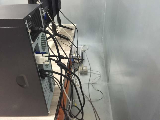
75 Page (74) of (100) 6. Test Setup Photographs 6.1 Conducted Emission D-SUB, DVI, HDMI Mode
")

76 Page (75) of (100) WIFI Mode
 -")
77 Page (76) of (100) - Telecommunication Emission


78 Page (77) of (100) 6.2 Radiated Emission * Below 1 GHz D-SUB, DVI, HDMI Mode
")

79 Page (78) of (100) WIFI Mode
 * Above")

80 Page (79) of (100) * Above 1 GHz D-SUB, DVI, HDMI Mode
")

81 Page (80) of (100) WIFI Mode

82 Page (81) of (100) 6.3 Harmonics / Voltage Fluctuations D-SUB, DVI, HDMI Mode WIFI Mode


83 Page (82) of (100) 6.4 Electrostatic Discharge Immunity D-SUB, DVI, HDMI Mode WIFI Mode


84 Page (83) of (100) D-SUB, DVI, HDMI Mode 1.Contack Discharge 3.Air Discharge 2.Contack Discharge

85 Page (84) of (100) WIFI Mode 1.Air Discharge


86 Page (85) of (100) 6.5 Radio frequency electromagnetic field immunity D-SUB, DVI, HDMI Mode WIFI Mode


87 Page (86) of (100) 6.6 Fast Transient Immunity D-SUB, DVI, HDMI Mode WIFI Mode

88 Page (87) of (100) 6.7 Surge Immunity D-SUB, DVI, HDMI Mode WIFI Mode


89 Page (88) of (100) 6.8 Radio-frequency continuous conducted Immunity D-SUB, DVI, HDMI Mode WIFI Mode


90 Page (89) of (100) 6.9 Voltage Dips and Voltage Interruptions Immunity D-SUB, DVI, HDMI Mode WIFI Mode
 7.")

91 Page (90) of (100) 7. External Photographs [ FRONT VIEW] [ REAR VIEW]

92 Page (91) of (100) LCD MONITOR Model No : SMT-3232A Manufacturer : Tianjin Samsung Electronics Co.,Ltd. Made in of Chnia [LABEL VIEW]

93 Page (92) of (100) 8. Internal Photographs [INTERNAL VIEW]
 Main")

94 Page (93) of (100) Main Board [TOP VIEW] [BOTTOM VIEW]
 Power")

95 Page (94) of (100) Power Board [TOP VIEW] [BOTTOM VIEW]
 Board")
![1 [TOP VIEW]](/docs-images/93/112212181/images/96-1.jpg "[BOTTOM")
96 Page (95) of (100) Board 1 [TOP VIEW] [BOTTOM VIEW]
 Butten")

97 Page (96) of (100) Butten Board [TOP VIEW] [BOTTOM VIEW]

98 Page (97) of (100) LCD [TOP VIEW] [BOTTOM VIEW]
 Module")
![[TOP VIEW]](/docs-images/93/112212181/images/99-1.jpg "[BOTTOM")
99 Page (98) of (100) Module [TOP VIEW] [BOTTOM VIEW]
Declaration of Conformity.
 Declaration of Conformity. Type of equipment: Brand Name /Trade Mark: Type designation /model: Applicant: LCD MONITOR HANWHA SMT-1935 Hanwha Techwin Company Limited In accordance with the following Directives:
Declaration of Conformity.
 Declaration of Conformity. Type of equipment: Brand Name /Trade Mark: Type designation /model: Applicant: NETWORK CAMERA SAMSUNG SBP-300HFP SAMSUNG TECHWIN CO.,LTD. In accordance with the following Directives:
EU Declaration of Conformity.
 EU Declaration of Conformity. SEW-3041WN We hereby declare that the product Type of equipment : NETWORK CAMERA Brand Name / Trade Mark : SAMSUNG Model number : QNO-7030RP Variant Model : QNO-7010RP, QNO-7020RP
KES. hereby. Dong Hun, Jang. Signature: Model: FCC Rule Part(s): 84, Jeongdong-r. Park KES-E1-15T0042 SNB-6011N. specified
: 84, Jeongdong-r. Park KES-E1-15T0042 SNB-6011N. specified") VERIFICATION OF FCCC PART 15 COMPLIANCE KES hereby verify that t the subject product compliesc s with all the electromagnetic emission specified in the FCC Rule Part 15 Product Description: Model/Brand
VERIFICATION OF FCCC PART 15 COMPLIANCE KES hereby verify that t the subject product compliesc s with all the electromagnetic emission specified in the FCC Rule Part 15 Product Description: Model/Brand
Revision history. Revision Date of issue Test report No. Description KES-E Initial
 Page (2) of (52) Revision history Revision Date of issue Test report No. Description - 02.06.2012 Initial Page (3) of (52) TABLE OF CONTENTS 1 General Information 4 2 Product Labelling Requirements 8 3
Declaration of Conformity.
 Declaration of Conformity. Type of equipment: Brand Name /Trade Mark: Type designation /model: Applicant: NETWORK CAMERA SAMSUNG SNV-L6083RP Samsung Techwin Co., Ltd. In accordance with the following Directives:
Declaration of Conformity.
 Declaration of Conformity. Type of equipment: Brand Name /Trade Mark: Type designation /model: Applicant: NETWORK CAMERA SAMSUNG SNV-L5083RP Samsung Techwin Co., Ltd. In accordance with the following Directives:
EMC Test Report. Report Number: M030826
 Page 1 of 36 EMC Technologies Pty Ltd ABN 82 057 105 549 57 Assembly Drive Tullamarine Victoria Australia 3043 Ph: + 613 9335 3333 Fax: + 613 9338 9260 email: melb@emctech.com.au EMC Test Report Report
Declaration of Conformity.
 Declaration of Conformity. Type of equipment: Brand Name /Trade Mark: Type designation /model: Variant Model Name: Applicant: CAMERA HOUSING SAMSUNG TECHWIN CO., LTD. SCX-FH200B SHB-4200 SAMSUNG TECHWIN
EN 55022: 2010+AC:2011 Clause 6.1 Pass. Harmonic Current EN :2006+A1:2009+A2:2009 Class A N/A
 Reference No.: WT12106773-N-S-E Page 2 of 33 1 Test Summary Test Item Mains Terminal Disturbance Voltage, 150KHz to 30MHz Radiation Emission, 30MHz to 1000MHz EMISSION Test Standard Class / Severity Result
Overview of EMC Regulations and Testing. Prof. Tzong-Lin Wu Department of Electrical Engineering National Taiwan University
 Overview of EMC Regulations and Testing Prof. Tzong-Lin Wu Department of Electrical Engineering National Taiwan University What is EMC Electro-Magnetic Compatibility ( 電磁相容 ) EMC EMI (Interference) Conducted
TEST SUMMARY. Prüfbericht - Nr.: Test Report No.: Seite 2 von 27. Page 2 of 27
 15072768 001 Seite 2 von 27 Page 2 of 27 TEST SUMMARY 4.1.1 HARMONICS ON AC MAINS 4.1.2 VOLTAGE CHANGES, VOLTAGE FLUCTUATIONS AND FLICKER ON AC MAINS 4.1.3 MAINS TERMINAL CONTINUOUS DISTURBANCE VOLTAGE
TEST SUMMARY. Prüfbericht - Nr.: Test Report No.: Seite 2 von 25. Page 2 of 25
 15072259 001 Seite 2 von 25 Page 2 of 25 TEST SUMMARY 4.1.1 HARMONICS ON AC MAINS 4.1.2 VOLTAGE FLUCTUATIONS ON AC MAINS 4.1.3 MAINS TERMINAL CONTINUOUS DISTURBANCE VOLTAGE 4.1.4 DISCONTINUOUS INTERFERENCE
EN 55015: 2013 Clause Pass. EN 55015: 2013 Clause Pass. EN 55015: 2013 Clause Pass
 Reference No.: WTD15S0730643E Page 2 of 42 1 Test Summary Test Item Conducted Disturbance at Mains Terminal, 9kHz to 30MHz Radiation electromagnetic disturbance, 9kHz to 30MHz Radiation Emission, 30MHz
TEST REPORT... 1 CONTENT...
 CONTENT TEST REPORT... 1 CONTENT... 2 1 TEST RESULTS SUMMARY... 3 2 EMC RESULTS CONCLUSION... 4 3 LABORATORY MEASUREMENTS... 6 4 EMI TEST... 7 4.1 CONTINUOUS CONDUCTED DISTURBANCE VOLTAGE TEST... 7 4.2
2620 Modular Measurement and Control System
 European Union (EU) Council Directive 89/336/EEC Electromagnetic Compatibility (EMC) Test Report 2620 Modular Measurement and Control System Sensoray March 31, 2006 April 4, 2006 Tests Conducted by: ElectroMagnetic
Discontinuous Disturbance (Click) EN : 2011 Clause Pass Radiated Emission, 30MHz to 1000MHz
 EN : 2011 Clause Pass Radiated Emission, 30MHz to 1000MHz") Reference No.: WTU15U0933879E Page 2 of 45 1 Test Summary Test Item Mains Terminal Disturbance Voltage, 148.5kHz to 30MHz Disturbance Power, 30MHz to 300MHz EMISSION Test Standard Class / Severity Result
Reference No.: WTU15U0933879E Page 2 of 45 1 Test Summary Test Item Mains Terminal Disturbance Voltage, 148.5kHz to 30MHz Disturbance Power, 30MHz to 300MHz EMISSION Test Standard Class / Severity Result
TABLE OF CONTENTS. 1. General Description of EUT General Information of Test Conducted Emission Tests 7-10
 TABLE OF CONTENTS 1. General Description of EUT 3 2. General Information of Test 4-6 3.1 Conducted Emission Tests 7-10 3.2 Radiated Emission Tests 11-13 3.3 Radiated Electromagnetic disturbance Test 14-18
ITUNER NETWORKS CORPORATION EMC REPORT Fremont Blvd. Fremont, CA
 Shenzhen BST Technology Co., Ltd. ITUNER NETWORKS CORPORATION EMC REPORT Prepared For : ITUNER NETWORKS CORPORATION 47801 Fremont Blvd. Fremont, CA. 94538 Product Name: PicoPSU-150 Trade Name: PicoPSU
EMC TEST REPORT CE TEST REPORT. Report Number : ETLE Report issue date: August 21, 2009
 CE TEST REPORT Report Number : ETLE080219.157.1 Report issue date: August 21, 2009 Model / Serial No. : NSD-S360 / NONE Multiple Model Name : NSD-S300, NSD-S230, NSD-S680, NSD-H350, NSD-S330, NSD-S370,
Shenzhen Toby Technology Co., Ltd. EMC Test Report. Report No.: TB-EMC Page: 1 of 20
 Shenzhen Toby Technology Co., Ltd. Report No.: TB-EMC125641 Page: 1 of 20 EMC Test Report Application No. : TB12114299 Applicant : Newmb Technology Co., Ltd. Equipment Under Test (EUT) EUT Name : USB HUB
Contents. Report No.: EMC-CE-2114 Page: 2 of 39
 Page: 2 of 39 Contents 1. Applicant information... 3 2. Laboratory information... 4 3. Test system configuration... 5 3.1 Operation environment... 5 3.2 Measurement Uncertainty... 6 4. Description of E.U.T...
Harmonic Current emission EN :2014 Class A Pass. Voltage Fluctuation and Flicker EN :2013 Clause 5 Pass
 Reference No.: WTS15F0323845E Page 2 of 33 1 Test Summary Test Item Mains Terminal Disturbance Voltage, 148.5kHz to 30MHz Disturbance Power, 30MHz to 300MHz Discontinuous Disturbance (Click) Radiated Emission,
Discontinuous Disturbance (Click) EN :2006+A1:2009+A2:2011 Clause N/A** Radiated Emission, 30MHz to 1000MHz
 EN :2006+A1:2009+A2:2011 Clause N/A** Radiated Emission, 30MHz to 1000MHz") Reference No.: WTN13F0706038E Page 2 of 40 1 Test Summary Test Item Mains Terminal Disturbance Voltage, 148.5kHz to 30MHz Disturbance Power, 30MHz to 300MHz EMISSION Test Standard Class / Severity Result
Reference No.: WTN13F0706038E Page 2 of 40 1 Test Summary Test Item Mains Terminal Disturbance Voltage, 148.5kHz to 30MHz Disturbance Power, 30MHz to 300MHz EMISSION Test Standard Class / Severity Result
Test Report. Guangdong East Power Co., Ltd. Fully Automatic AC Voltage Regulator. Brand Name:
 Test Report Applicant: Product Name: Brand Name: Model No.: Guangdong East Power Co., Ltd. Fully Automatic AC Voltage Regulator EAST ZTY-30KVA Date of Receipt : Aug. 30, 2013 Date of Test: Sep. 03, 2013
EMC VERIFICATION SUMMARY Report No.: SZHH
 EMC VERIFICATION SUMMARY Toy ITE Others Additional Models: 0801 to 0899 INCLUSIVE, 0804, 0804W, 0805, 0806, 0807, 0808, 0809, 0811, 0811W, 0812, 0813, 0814,0815, 0816, 0817,0817 ROOM 619, 6/F. PENINSULA
EMC standards. Presented by: Karim Loukil & Kaïs Siala
 Training Course on Conformity and Interoperability on Type Approval testing for Mobile Terminals, Homologation Procedures and Market Surveillance, Tunis-Tunisia, from 20 to 24 April 2015 EMC standards
EMC TEST REPORT For MPP SOLAR INC Inverter/ Charger Model Number : PIP 4048HS
 EMC-E20130903E EMC TEST REPORT For MPP SOLAR INC Inverter/ Charger Model Number : PIP 4048HS Prepared for : MPP SOLAR INC Address : 4F, NO. 50-1, SECTION 1, HSIN-SHENG S. RD. TAIPEI, TAIWAN Prepared by
ELECTRONICS TESTING CENTER(ETC), TAIWAN
, TAIWAN") File No. : 06-03-RBF-111-01 EMC TESTING DEPARTMENT II Page: 1 / 35 TEST REPORT Responsible Party Manufacturer Description of Product Trade Name : Huan Vu Enterprise Co., Ltd. : Huan Vu Enterprise Co.,
File No. : 06-03-RBF-111-01 EMC TESTING DEPARTMENT II Page: 1 / 35 TEST REPORT Responsible Party Manufacturer Description of Product Trade Name : Huan Vu Enterprise Co., Ltd. : Huan Vu Enterprise Co.,
CE Conformance EMC Test Report
 CE Conformance EMC Test Report Test Report No. : TK-CC110005 Date of Issue : 1/20/2011 Description of Product. Variant Model. Applicant Manufacturer Applicable Regulation : Mat Cable : DW20W 1.0M, DW20W
TABLE OF CONTENTS 1. GENERAL DESCRIPTION OF EUT 3 2. GENERAL INFORMATION OF TEST CONDUCTED EMISSION TEST RADIATED EMISSION TEST 11
 Page : 2 / 38 TABLE OF CONTENTS 1. GENERAL DESCRIPTION OF EUT 3 2. GENERAL INFORMATION OF TEST 4 3.1 CONDUCTED EMISSION TEST 7 3.2 RADIATED EMISSION TEST 11 3.3 ELECTROSTATIC DISCHARGE IMMUNITY TEST 14
EMC TEST REPORT CE TEST REPORT. for Audio / Video receivers and associated equipment
 CE TEST REPORT for Audio / Video receivers and associated equipment Report Number : ETLE100104.03 Report Issue Date: January 15, 2010 Model / Serial No. : WSTA-VM300P / NONE Multiple Model Name : WSTA-VM320P,
Page: 1 of 20 EMC TEST REPORT EN55024:1998+A2:2003
 Page: 1 of 20 EMC TEST REPORT Reference No. Applicant : WT05060412 : Gembird Electronics Ltd. Equipment Under Test (EUT) : Product Name : Cable Standards Model No : UAS111-M, UAS111, UAS112 : EN55022:1998+A2:2003
TABLE OF CONTENTS. Report Reference No.: GST E Issued: Oct. 21, 2011 Revised: None. Page 2 of 46
 TABLE OF CONTENTS 1. GENERAL INFORMATION...5 1.1 PRODUCT DESCRIPTION FOR EQUIPMENT UNDER TEST (EUT)...5 1.2 OBJECTIVE...5 1.3 RELATED SUBMITTAL(S)/GRANT(S)...5 1.4 TEST METHODOLOGY...5 1.5 TEST FACILITY...5
Certificate of Test AND KEEPS ALL REQUIREMENTS ACCORDING THE FOLLOWING REGULATIONS IEC :2001 IEC :2007
 Certificate of Test WE HEREBY CERTIFY THAT: Certificate No.: R07122709E Yuan Hsun Electric Co., Ltd. No. 57, Chung He Rd, Zuo-Ying Dist., Kaohsiung City 813, Taiwan R.O.C. Quad photobeam detector Quad-200CS
EMC REPORT. ShenZhen KY Technology Co.,Ltd. No.369, BaoTian 1st RD, TieGang Industrial Park, Xixiang Town, Baoan District, ShenZhen, PRC.
 Report No.: UNI2016121702ER-01 Page 1 / 30 ShenZhen KY Technology Co.,Ltd EMC REPORT Prepared For: ShenZhen KY Technology Co.,Ltd Product Name: Smart bracelet No.369, BaoTian 1st RD, TieGang Industrial
EMC TEST REPORT. For. Boardcon Technology Limited. MINI9G45 Computer on Module. Model No. : MINI9G45
 REPORT NO. PRSZ15110502E EMC TEST REPORT For Boardcon Technology Limited. MINI9G45 Computer on Module Model No. : MINI9G45 Prepared For : Boardcon Technology Limited. : Room 702, Hua Feng Xin An Business
EN61326 EMC COMPLIANCE REPORT on the LP Series Ultrasonic Transmitter Remote Amplifier and Transducer for Hawk Measurement Systems Pty Ltd
 Page 1 of 15 EMC Technologies Pty Ltd ABN 82 057 105 549 57 Assembly Drive Tullamarine Victoria Australia 3043 Ph: + 613 9335 3333 Fax: + 613 9338 9260 email: melb@emctech.com.au EN61326 EMC COMPLIANCE
REVISION HISTORY. The revision history for this document is shown in table. HCT-EM-1801-FC037 January 22, 2018 Initial Release
 REVISION HISTORY The revision history for this document is shown in table. Version Issue Date Description HCT-EM-1801-FC037 January 22, 2018 Initial Release HCT-EM-1801-FC037-R1 January 26, 2018 Revision
TABLE OF CONTENTS. 1. General Description of EUT General Information of Test Conducted Emission Tests 7-12
 TABLE OF CONTENTS 1. General Description of EUT 3 2. General Information of Test 4-6 3.1 Conducted Emission Tests 7-12 3.2 Radiated Emission Tests 13-15 3.3 Radiated Electromagnetic disturbance Test 16-20
EMC TEST REPORT for : DONGGUAN EVER DEVELOPMENT ELECTRONIC CO., Electronic calculator Model No.: KF15758
 Page 1 of 20 Report No. R011604553E EMC TEST REPORT for DONGGUAN EVER DEVELOPMENT ELECTRONIC CO., LTD. Electronic calculator Model No.: KF15758 Prepared for Address Prepared by Address : DONGGUAN EVER
APPLICATION FOR EMC DIRECTIVE. On Behalf of. Shenzhen Qinhan Lighting Co., Ltd. led flood light. Trade Name:
 APPLICATION FOR EMC DIRECTIVE On Behalf of Shenzhen Qinhan Lighting Co., Ltd led flood light Trade Name: Model: QH-TGC-400W, QH-TGC-300W, QH-TGC-500W, QH-TGC-800W, QH-TGC-1000W Prepared For : Shenzhen
EMC TEST REPORT. For. Switching Mode Power Adaptor. Model No.: 9W/14.4V/EU(18V/1.0A), 19W/14.4V/EU(12V/1.5A)
, 19W/14.4V/EU(12V/1.5A)") EMC TEST REPORT For Company Limited Liability «Faraday Electronics» Switching Mode Power Adaptor Model No.: 9W/14.4V/EU(18V/1.0A), 19W/14.4V/EU(12V/1.5A) Prepared For : Company Limited Liability «Faraday
EMC TEST REPORT For Company Limited Liability «Faraday Electronics» Switching Mode Power Adaptor Model No.: 9W/14.4V/EU(18V/1.0A), 19W/14.4V/EU(12V/1.5A) Prepared For : Company Limited Liability «Faraday
EMC TEST REPORT. Report No.: TS EME Model No.: 33XR-A Issued Date: Jan. 08, 2009
 Page 1 of 18 EMC TEST REPORT Report No.: TS08100063-EME Model No.: 33XR-A Issued Date: Jan. 08, 2009 Applicant: Test Method/ Standard: Test By: FLUKE CORP. 6920 Seaway Blvd, M/S 266D Everett, WA 98203
EMC test report AU01+E04
 Customer: Altuflevskoye shosse,h.48,bld.1pr.1,room39 Moscow,127566 Russia EMC test report 130504-AU01+E04 This test report may not be copied or published in a part without the written authorization of
EN :2007+A1:2011 Electromagnetic compatibility Emission standard for residential, commercial and light-industrial environments
 EMC Page 3 / 33 Test report No.: EN 61000-6-3:2007+A1:2011 Electromagnetic compatibility Emission standard for residential, commercial and light-industrial environments Date of measurement: 2013-10-16
Revision history. Revision Date of issue Test report No. Description KES-RF-14T0042 Initial
 Page (2 ) of (34) Revision history Revision Date of issue Test report No. Description - 2014.08.25 Initial Page (3 ) of (34) TABLE OF CONTENTS 1. General information... 4 1.1. EUT description... 4 1.2.
TEST REPORT on behalf of Shanghai ZLAN Information Technology Co.,Ltd Serial Device Server
 TEST REPORT on behalf of Shanghai ZLAN Information Technology Co.,Ltd Serial Device Server Prepared For: Shanghai ZLAN Information Technology Co.,Ltd. Room 1205, Building D Everbright Exhibition Center,
EMC TEST REPORT. NORTE SIRIUS ENTERPRISE CO., LTD , Shin-Sheng St., Chung-Ho Dist, New Taipei City, Taiwan
 Page 1 of 32 EMC TEST REPORT Report No.: TS11020117-EME Model No.: NS-PSE, NS-POINTED, NS-PSQUARE, NS-PF-S, NS-PT, NS-PR, NS-PU, NS-PF-H, NS-BALIBA, NS-FLEXMA Issued Date: Mar. 01, 2011 Applicant: NORTE
ETSI EN V2.2.0 ( ) ETSI EN V2.1.1 ( ) TEST REPORT. United GULF GATE Co.
 ETSI EN V2.1.1 ( ) TEST REPORT. United GULF GATE Co.") ETSI EN 301 489-1 V2.2.0 (2017-03) ETSI EN 301 489-3 V2.1.1 (2017-03) TEST REPORT For United GULF GATE Co. Aladel Tower,F21,Fahad Al Salem St., State of KUWAIT Model: XT-10P Report Type: Amended Report
ETSI EN 301 489-1 V2.2.0 (2017-03) ETSI EN 301 489-3 V2.1.1 (2017-03) TEST REPORT For United GULF GATE Co. Aladel Tower,F21,Fahad Al Salem St., State of KUWAIT Model: XT-10P Report Type: Amended Report
EMC Test Report For Changzhou Airwheel Technology Co.,Ltd. Airwheel Model: A6S,A6,A6P,A6PS,A6T,A6TS
 EMC Test Report For Changzhou Airwheel Technology Co.,Ltd. Airwheel Model: A6S,A6,A6P,A6PS,A6T,A6TS Prepared For : Prepared By : Changzhou Airwheel Technology Co.,Ltd. Fl.5, East of No. 10 Building, high-tech
EMC TEST REPORT for SHENZHEN MUST ENERGY TECHNOLOGY CO., LTD
 Page 1 of 45 Report No. R011607240E EMC TEST REPORT for SHENZHEN MUST ENERGY TECHNOLOGY CO., LTD INVERTER CHARGER Model No.: PV35-4K DC24V MPK, PV35-4K DC48V MPK, PV35-5K DC48V MPK, PV35-6K DC48V MPK Prepared
CE Conformance EMC Test Report
 CE Conformance EMC Test Report Test Report No. : TK-CC100152 Date of Issue : 12/24/2010 Description of Product Model No. Variant Model. : Temperature Controller (include in heating cable) : DW25W : DW25W11L,
EMC REPORT DONGGUAN FIT-WATCH CO., LTD. 18#,Hedong No.1 road,jinsha village,changan town, Dongguan City, Guangdong Province.
 DONGGUAN FIT-WATCH CO., LTD. EMC REPORT Prepared For : DONGGUAN FIT-WATCH CO., LTD. 18#,Hedong No.1 road,jinsha village,changan town, Dongguan City, Guangdong Province Product Name : Trade Name : Model
By order of ZHONGSHAN LIANGYI LIGHTING CO., LTD. at Zhongshan, China
 4317137.50 EMC Test report for LED Fixed luminaires Models LED12036-1R, LED12036-2TU, LED120363R, LED12036-4TU2, LED12036-6TR, LED12036-1R CHR, LED12036-2TU CHR, LED12036-3R CHR, LED12036-4TU2 CHR, LED12036-6TR
EMC TEST REPORT for LEDELS LIGHTING CO., LTD. LED module Model No. : LL-F12T4815X6B
 Page 1 of 27 Report No. R011412016E-1 EMC TEST REPORT for LEDELS LIGHTING CO., LTD LED module Model No. : LL-F12T4815X6B Prepared for : LEDELS LIGHTING CO., LTD Address : 5F, Block C, Mingjinhai Ind. Park,
EMC Test Report. Product. Model Number. Prepared for : Shenzhen top technology co., LTD Address : No 2.First Rd Of Lucky,Longgang Ping Shenzhen China
 EMC-Report No.:SZZCT1502030B-EMC-02 EMC Test Report Product Model Number : Drift car : P01 Prepared for : Shenzhen top technology co., LTD Address : No 2.First Rd Of Lucky,Longgang Ping Shenzhen China
EMC TEST REPORT For CE
 EMC TEST REPORT For CE Test Report No. : CTK-2013-01069 Date of Issue : 2013-07-02 Kind of Product : FnIO S-Series Basic Model/Type No. : NA-9211, ST-5725, ST-5726 Variant Model/Type No. : NA-9212 Applicant
TABLE OF CONTENTS Page 1 of VERIFICATION OF CONFORMITY SYSTEM DESCRIPTION PRODUCT INFORMATION SUPPORT EQUIPMENT
 ELECTROMAGNETIC COMPLIANCE TEST REPORT For Electric nail art drill Model Name: HBS-021, HBS-278, HBS-288, HBS-530, HBS-540 Brand Name: Date of Issue: May 7, 2011 Prepared For Houbos Hardware & Electrical
Shenzhen CTL Electromagnetic Technology Co., Ltd. Tel: Fax: TEST REPORT
 Shenzhen CTL Electromagnetic Technology Co., Ltd. Tel: +86-755-89486194 Fax: +86-755-89486194-805 TEST REPORT EN 55014-1 / EN 55014-2 Electromagnetic compatibility Requirements for household appliances,
EMC Test report for LED Panel Light Models , , , , ,
 4326247.50 EMC Test report for LED Panel Light Models 000529, 000530, 000531, 000532, 000535, 000536 Guangzhou, date of issue: 2016-02-24 Author:Jazz Liang By order of Marvo Verlichting B.V. at Hoogeveen,
Prepared for Address. : KST DIGITAL TECHNOLOGY LIMITED : No.226, Pangu Street, Meixian, Meizhou, Guangdong. Prepared by
 EMC TEST REPORT For KST DIGITAL TECHNOLOGY LIMITED Coreless Servo Model No.: X12-508 Additional Model No.: DS215MG, DS315MG, DS213MG, DS313MG, DS12C, DS12T, X12-306 Prepared for Address : KST DIGITAL TECHNOLOGY
EMC TEST REPORT. for. Coliy Technology Co.,Ltd. Fluxgate Gaussmeter
 Page 1 of 48 EMC TEST REPORT for Coliy Technology Co.,Ltd. Fluxgate Gaussmeter Prepared for : Coliy Technology Co.,Ltd. Address : Block B,9 th Floor,Xinzhongtai Business Building,Gushu 2nd Road,Xi Town,Bao
EMC TEST REPORT For. Shenzhen Ruideou Keji Youxian Gongsi. Shenzhen Ruideou Keji Youxian Gongsi
 EMC TEST REPORT For Shenzhen Ruideou Keji Youxian Gongsi Product Name: Trademark: Milligram Scale WAOAW Model Number: W-01-50 Prepared For : Address: Prepared By : Address: Shenzhen Ruideou Keji Youxian
FCC TEST REPORT. Table of Contents. Report no. ETLE , Page 2 of 21
 Table of Contents FCC Measurement Report 1. Introduction 2. Product Information 3. Description of Tests 4. Test Condition 5. Test Results 5.1 Summary of Test Results 5.2 Conducted Emissions Measurement
EMC TEST REPORT. Report No.: CE10-LIE040101E
 EMC TEST REPORT Report No.: CE10-LIE040101E Product: LED TUBE Model No.: T10, T8, T5 Applicant: Shenzhen Saiju Electronic Co., Ltd. Address: 2nd. Xianshun Industrial Park, Gushu, Xixiang, Bao an, Shenzhen,
TEST SUMMARY Seite 2 von 27. Prüfbericht - Nr.: Test Report No HARMONICS ON AC MAINS RESULT: Passed
 17035561 001 Seite 2 von 27 Page 2 of 27 TEST SUMMARY 5.1.1 HARMONICS ON AC MAINS RESULT: Passed 5.1.2 VOLTAGE FLUCTUATIONS ON AC MAINS RESULT: Passed 5.1.3 TERMINAL CONTINUOUS DISTURBANCE VOLTAGE AT RESULT:
By order of American Power Conversion Holdings Inc. at New Taipei City, Taiwan
 4322705.50 EMC Test report for Plug-in adaptor Models PM1W-IT, PM1WU2-IT, PM1W-GR, PM1W-SP, PM1W-RS, PM1WB-RS, PM1WU2-GR, PM1WU2-SP, PM1WU2-RS, PM1WBU2-RS, PM1W-UK, PM1WU2-UK, PM1W-FR, PM1WU2-FR Guangzhou,
EMC TEST REPORT For ShenZhen ZhangQing Electronic LTD poe tester Model No.: WS POE Tester/Detector Additional Model No: Please Refer to Page 8
 EMC TEST REPORT For ShenZhen ZhangQing Electronic LTD poe tester Model No.: WS POE Tester/Detector Additional Model No: Please Refer to Page 8 Prepared for Address : ShenZhen ZhangQing Electronic LTD :
Test Report GUANGDONG EAST POWER CO., LTD
 Test Report Applicant: Product Name: Brand Name: Model No.: GUANGDONG EAST POWER CO., LTD Online High Frequency UPS EAST EA906IIRTS, EA906IIRTH Date of Receipt : Feb. 26, 2014 Date of Test: Mar. 24, 2014
Test Report Report No.: G150424B02-03EN Date: May. 07, 2015 Page 1 of 49
 Test Report Report No.: G150424B02-03EN Date: May. 07, 2015 Page 1 of 49 The following information was submitted and identified by/on behalf of the client as: Applicant : Ningbo Shanhuang Electric Appliance
Report for Excelsys EMC Measurements for 4Xgen Purchase Order: Project Number EMT07J026 Rev. B
 Report for Excelsys on EMC Measurements for 4Xgen Purchase Order: Project Number EMT07J026 Rev. B Rev Date Comment A April 2007 Change in DoC content B May 2007 Added Immunity Section EMT is a TÜV Appointed
EMISSION. EN : 2006 Clause 6.5 Pass. Harmonic Current EN : 2006+A1: 2009+A2: 2009 Class A Pass
 Reference No.: WTS14S0513592E Page 2 of 44 1 Test Summary EMISSION Test Item Mains Terminal Disturbance Voltage, 150kHz to 30MHz Telecommunication ports interference voltage, 150KHz to 30MHz Radiation
CE CONFORMANCE REPORT
 Accredited Testing Laboratory under the terms of ISO/IEC 17025 CE CONFORMANCE REPORT EMC DIRECTIVE 2004/108/EC for PRODUCT: HIGH DEFINITION NETWORK CAMERA MODEL NAME: LND5110 AUTHORIZED LG Electronics
Contents. Report No.: EMC-FCC-1985 Page: 2 of 26
 Page: 2 of 26 Contents 1. Applicant information...3 2. Laboratory information...4 3. Test system configuration...5 3.1 Operation environment...5 3.2 Measurement Uncertainty...6 4. Description of E.U.T...7
EMC Test Report FATEK AUTOMATION CORP. FATEK. FBs-TBOX N/A
 EMC Test Report Applicant: Address of Applicant: Trade Name: FATEK AUTOMATION CORP. 26FL, NO.29, SEC.2, JUNGJENG E. RD., DANSHUEI DIST., NEW TAIPEI CITY, TAIWAN, R.O.C. FATEK Equipment Under Test: Training
EMC TEST REPORT. For. Soma Medical (Sabah) Sdn Bhd ( D) UVGI AIR STERILIZER. Model No.: SM 20
 Sdn Bhd ( D) UVGI AIR STERILIZER. Model No.: SM 20") EMC TEST REPORT For Soma Medical (Sabah) Sdn Bhd (1248058-D) UVGI AIR STERILIZER Model No.: SM 20 Prepared For : Soma Medical (Sabah) Sdn Bhd (1248058-D) : Block E, Lot 28, 2nd floor, Signature Office,
EMC TEST REPORT For Soma Medical (Sabah) Sdn Bhd (1248058-D) UVGI AIR STERILIZER Model No.: SM 20 Prepared For : Soma Medical (Sabah) Sdn Bhd (1248058-D) : Block E, Lot 28, 2nd floor, Signature Office,
BUREAU VERITAS. itaste svd
 BUREAU VERITAS TEST REPORT No.: (5213)095-0238 TEST REPORT To: INNOKIN TECHNOLOGY CO., LTD I Fax: I -- Attn: -- I -- I Address: Buildinq 6, XinXinTian Industrial Park, XinSha Road, Sha.Jinq street, ShenZhen,
TEST REPORT Title 47-Telecommunication
 TEST REPORT Title 47-Telecommunication Chapter I - Federal Communications Commission Subchapter A - General Part 5 - Radio Frequency Devices Subpart B - Unintentional Radiators Report Reference No....
1 SUMMARY OF STANDARDS AND RESULTS
 1 SUMMARY OF STANDARDS AND RESULTS 1.1 Description of Standards and Results The EUT have been tested according to the applicable standards as referenced below: EMISSION Description of Test Item Standard
FCC PART 15, CLASS B MEASUREMENT AND TEST REPORT. NanJing JingZe Lighting Technology Co.,Ltd
 FCC PART 15, CLASS B MEASUREMENT AND TEST REPORT For NanJing JingZe Lighting Technology Co.,Ltd No. 30, Hengfa Rd., National Economic Technological Development Zone, Nanjing, Jiangsu, China Tested Model:
BS EN TESTS ON THE IT TOXIC GAS DETECTOR MODULE
 Page 1 of 18 Interference Testing And Consultancy Services (Pty) Ltd ITC SERVICES (PTY) LTD Reg 88/002032/07 Plot 44 Kameeldrift East, Pretoria Private Bag X13 Lynn East 0039 Republic of South Africa Tel
FCC TEST REPORT. Table of Contents. FCC Measurement Report
 Table of Contents FCC Measurement Report 1. Introduction 2. Product Information 3. Description of Tests 4. Test Condition 5. Test Results 5.1 Summary of Test Results 5.2 Radiated Emissions Measurement
TEST REPORT. draft draft draft. TRF Originator...: Shenzhen CTL Testing Technology Co., Ltd. Master TRF...: Dated
 Shenzhen CTL Testing Technology Co., Ltd. Tel: +86-755-89486194 Fax: +86-755-26636041 TEST REPORT EN 55014-1 / EN 55014-2 Electromagnetic compatibility Requirements for household appliances, electric tools
EMISSION TEST REPORT
 Page 1 of 23 EMISSION TEST REPORT Test Report No. Applicant Address Manufacturer Address Type of Equipment Model Name Serial number Total page of Report : E05OR-057 : Win4NET Co., Ltd. : KOLON Digital
CTS (NINGBO) TESTING SERVICE TECHNOLOGY INTERNATIONAL OPERATE ACCORDING TO ISO/IEC EMC TEST REPORT
 TESTING SERVICE TECHNOLOGY INTERNATIONAL OPERATE ACCORDING TO ISO/IEC EMC TEST REPORT") CTS (NINGBO) TESTING SERVICE TECHNOLOGY INTERNATIONAL OPERATE ACCORDING TO ISO/IEC 17025 EMC TEST REPORT TEST REPORT NUMBER : CNB3150602-00399-E 2/F., South Tower, Huoju Building, No.181, Canghai Road,
CTS (NINGBO) TESTING SERVICE TECHNOLOGY INTERNATIONAL OPERATE ACCORDING TO ISO/IEC 17025 EMC TEST REPORT TEST REPORT NUMBER : CNB3150602-00399-E 2/F., South Tower, Huoju Building, No.181, Canghai Road,
Test and Measurement for EMC
 Test and Measurement for EMC Bogdan Adamczyk, Ph.D., in.c.e. Professor of Engineering Director of the Electromagnetic Compatibility Center Grand Valley State University, Michigan, USA Ottawa, Canada July
FCC Test Report. Report No.: PTCDQ FC01
 Page 1 of 63 FCC Test Report Report No.: PTCDQ04170450501-FC01 FCC ID : 2AL2XW801 APPLICATION PURPOSE : Original Equipment PRODUCT DESIGNATION : WIFI DoorBell BRAND NAME : EASTIC MODEL NAME : W801, W802,
Report for Excelsys EMC Measurements for 6Xgen Purchase Order: by Project Number EMT08J027
 Report for Excelsys on EMC Measurements for 6Xgen Purchase Order: by email Project Number EMT08J027 Tom O Brien, Engineering Director ElectroMagnetic Technologies Ltd, Cork, June 2007 Executive Summary
EMC TEST REPORT. Report No. : EM/2004/10096 Page : 1 of 19
 EMC TEST REPORT Page : 1 of 19 Equipment Under Test Model No. Applicant Address of Applicant : Bluetooth Headset : FB-HS01 : Formosa Teletek Corporation : 358, Huaya 2 nd Rd., Gueishan shiang, Taoyuan,
SUZHOU MAILI ELECTRICAL APPLIANCE CO., LTD NO.666,JIANLIN RD, XUGUAN SUBAREA, SUZHOU HIGH-TECH ZONE
 EMC TEST REPORT For SUZHOU MAILI ELECTRICAL APPLIANCE CO., LTD Product Name: Pure sine wave power inverter Trademark: Model : Prepared For : Address: Prepared By : Address: ML-1000W ML-300W---ML-8000W.
Page: 1 of 46 EMC TEST REPORT : SISF, SISF-2, SISFN-BLACK, SISFN-2-BLACK
 Page: 1 of 46 Reference No. Applicant : WT05060414 EMC TEST REPORT : Gembird Electronics Ltd. Equipment Under Test (EUT) : Product Name : Advanced surge protection Model No. : SISF, SISF-2, SISFN-BLACK,
VERIFICATION OF FCC PART 15 COMPLIANCE
 VERIFICATION OF FCC PART 15 COMPLIANCE KES hereby verify that the subject product complies with all the electromagnetic emission specified in the FCC Rule Part 15 Product Description: NETWORK CAMERA Model/Brand
Page: 1 of 41 EMC TEST REPORT. Product Name : Multi-socket with surge protection : SPG3-B-10, SPG3-B-15, SPG3-B-5, SPG3-B-6
 Page: 1 of 41 EMC TEST REPORT Reference No. Applicant : WT05060416 : Gembird Electronics Ltd. Equipment Under Test (EUT) : Product Name : Multi-socket with surge protection Standards Model No. : SPG3-B-10,
TEST REPORT. Product: Thermo-Hygrometer Model No.: FL-201, FL-201W Trade mark: N/A Report No.: TCT151014E001 Issued Date: Oct. 15, 2015.
 TEST REPORT Product: Thermo-Hygrometer Model No.: FL-201, FL-201W Trade mark: N/A Report No.: TCT151014E001 Issued Date: Oct. 15, 2015 Issued for: Shenzhen Flus Technology Co., Ltd 3rd Floor, Lantian Building,
CE/EMC TEST REPORT. For HK QNOVATOR TECHNOLOGY CO.,LIMITED GS02-M X1, BL02, GS01, GS01-M, GS02, GS03, GS04, GS05, GS06, GS07, GS08, GS09, GS10
 CE/EMC TEST REPORT For HK QNOVATOR TECHNOLOGY CO.,LIMITED Product Name: Vacuum Tube Amplifier Trademark: Model Number: Prepared For: Address: Gemtune GS02-M X1, BL02, GS01, GS01-M, GS02, GS03, GS04, GS05,
EMC Testing Report. StarCam Genie N/A MICRO-STAR INT L CO., LTD.
 EMC Testing Report Equipment Under Test MSI StarCam Genie Model Number Serial No. Applicant Address of Applicant StarCam Genie N/A MICRO-STAR INT L CO., LTD. No.69, Lide St., Jhonghe City, Taipei County
CENTRE OF TESTING SERVICE INTERNATIONAL
 CENTRE OF TESTING SERVICE INTERNATIONAL OPERATE ACCORDING TO ISO/IEC 17025 FCC TEST REPORT TEST REPORT NUMBER : CGZ3150202-00097-E A101,No.65,Zhuji Highway,Tianhe District,Guangzhou, Guangdong, China Report
Page 1 of 51 Report No.: T TEST REPORT FCC ID: 2AGJ5WAP-30. In Accordance with: FCC PART 15, SUBPART C : 2015 (Section 15.
 Page 1 of 51 Report No.: T1851663 01 TEST REPORT FCC ID: 2AGJ5WAP-30 Applicant Address : Gonsin Conference Equipment Co., Ltd : No.401-406,Block C, Idea Industry Park, No.41 Fengxiang Road, Shunde, Foshan,
CTS (NINGBO) TESTING SERVICE TECHNOLOGY INTERNATIONAL OPERATE ACCORDING TO ISO/IEC EMC TEST REPORT
 TESTING SERVICE TECHNOLOGY INTERNATIONAL OPERATE ACCORDING TO ISO/IEC EMC TEST REPORT") CTS (NINGBO) TESTING SERVICE TECHNOLOGY INTERNATIONAL OPERATE ACCORDING TO ISO/IEC 17025 EMC TEST REPORT TEST REPORT NUMBER : CGZ3150428-00472-E-R1 2/F., South Tower, Huoju Building, No.181, Canghai Road,
CTS (NINGBO) TESTING SERVICE TECHNOLOGY INTERNATIONAL OPERATE ACCORDING TO ISO/IEC 17025 EMC TEST REPORT TEST REPORT NUMBER : CGZ3150428-00472-E-R1 2/F., South Tower, Huoju Building, No.181, Canghai Road,