Electrocardiogram (ECG)
|
|
|
- Blake Copeland
- 5 years ago
- Views:
Transcription
1 Vectors and ECG s

2 Vectors and ECG s 2
3 Electrocardiogram (ECG) Depolarization wave passes through the heart and the electrical currents pass into surrounding tissues. Small part of the extracellular current reaches the surface of the body. The electric potential generated can be recorded from electrodes placed on the skin An EKG is a comparison of two vectors It compares the heart vector showing current flow on the heart with the reference, recording lead vector on the body. 3
 Magnitude or size (amount of charge) Vector analysis explains the waves on an EKG Q S 4")
4 Vector diagrams Vectors are used to describe depolarization and repolarization events Vectors are arrows which show two things: Direction or pathway (of charge spread) Magnitude or size (amount of charge) Vector analysis explains the waves on an EKG Q S 4
5 EKG is Extracellular Recording Depolarization Repolarization Vectors will always be positioned so that head of vector is in area of positive charge; tail is in area of negative charge. i.e a Dipole 5
6 Electrophysiology
7 Electrophysiology
8 Electrophysiology


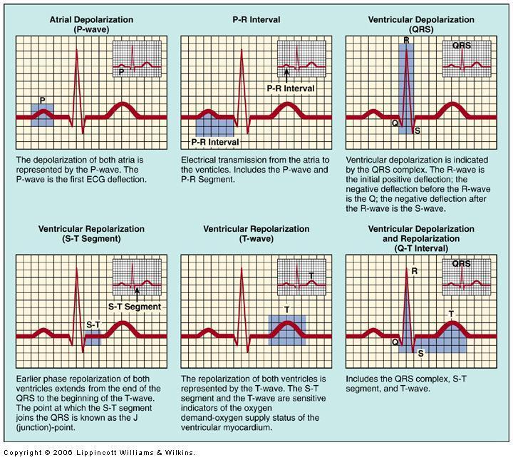
9 P wave represents depolarization of atria which causes atrial contraction Repolarization of atria not normally detectable on an ECG Excitation of bundle of His and bundle branches occur in middle of PR interval QRS complex reflects depolarization of ventricles T wave reflects repolarization of muscle fibers in ventricles
10 Rest No current flow, no vector. The following vectors represent the spread of negative charge during depolarization; Then the spread of positive charge during repolarization 10
11 SA: Sino-atrial node = depol SA nodal fibers, spread of neg charge over atria 11
12 The atria would start to depolarize to the right
13 The atria would start to depolarize to the right, depolarization continue and spreading. + 13
14 The atria would start to depolarize to the right, depolarization continue and spreading. + 14
15 The atria would start to repolarize down and to the left, as the current continues downward to the ventricles + 15
16 + 16
17 Atria now have repolarized and now have positive surface charge again. 17
18 Meanwhile, as the atria are repolarizing... We turn to the Depolarizing AV node AV: Atrioventricular Node These are small diameter fibers with few gap junctions; little or no detectable current flow 18
19 Septal Depolarization Moving down bundle of His; 19
20 20
21 21
22 Apex then Lateral walls 22
23 23
24 Through the thickness of the heart, from endo-, to myo-, to epicardium 24
25 25
26 Ventricles completely depolarized, negative surface charge No current No vector 26
27 Begin Ventricular Repolarization Spread of positive charge + 27
28 28
29 29
30 30
31 31
32 32
33 33
34 34
35 Rest End of cycle; No current flow, no vector. 35
36 Recording from Lead II Standard limb lead II 36
 the pen moves upward from baseline If the vectors run antiparallel (opposite direction) then the pen moves downward from baseline.")
37 The Rules of Vectors Analysis An EKG is a comparison of two vectors It compares the heart vector with the reference recording lead vector on the body. If the vectors run parallel (same direction) the pen moves upward from baseline If the vectors run antiparallel (opposite direction) then the pen moves downward from baseline. If the vectors are perpendicular, the pen remains on baseline. If there is no current flow, the pen remains on baseline. Each lead consists of two electrodes placed on the skin, with a voltmeter between them. The voltmeter is attached to a pen, which travels over paper running at 25 mm/sec. This produces waves called an electrocardiogram. 37
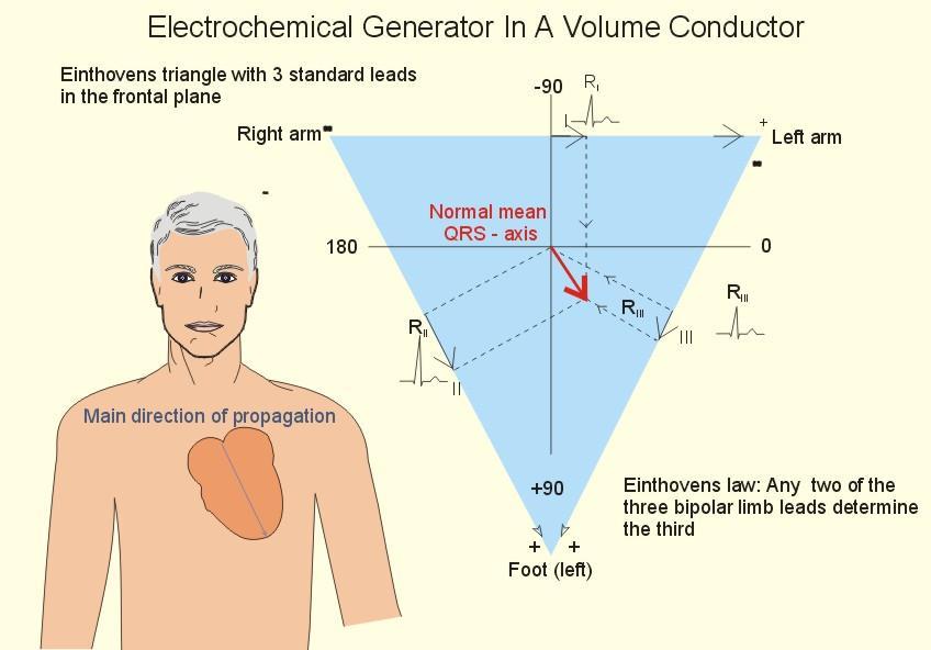
38 - I II III Einthoven s Triangle + + Bipolar Limb Leads 38
39 Atrial depolarization Pen here II V T The heart vector is parallel to the lead, but how can you confirm? 39

40 - Atrial depolarization II Av = A Cos θ Av is the projection of the vector on lead 2. A is the amplitude of the vector + 1. Draw a perpendicular line to the lead vector 2. Draw a line toward from the perpendicular vector toward your cardiac vector 40
41 Atrial depolarization II 41
42 AV nodal depolarization II 42
43 IV septal depol, from L to R II Anti-parallel! Pen deflects down Draw it! 43
44 IV septal depol, from base to apex II 44
45 Lateral walls depolarization II Draw it! 45
46 Depolarization complete; no current flow; pen returns to baseline II 46
47 Waiting to begin repolarization; no current flow II 47
48 Ventricular Repolarization begins II 48
49 Ventricular Repolarization II 49
50 Ventricular Repolarization complete; no current flow; pen on baseline II 50
51 Ventricular Repolarization complete; waiting to start all over again II End of one cardiac cycle 51
52 What does that tell you about the recording you obtain from each lead? Each lead describes the events on the heart from it s own point of view Reading from several leads gives you different points of view about the same set of repeating events (depol, repol) 52
53

54 A standard arrangement of electrodes for an ECG is called Einthoven triangle. They are bipolar leads. Einthoven Triangle
55 Summary: Bipolar Leads and Einthoven s Law Lead I - The negative terminal of the electrocardiograph is connected to the right arm, and the positive terminal is connected to the left arm. Lead II - The negative terminal of the electrocardiograph is connected to the right arm, and the positive terminal is connected to the left leg. Lead III - The negative terminal of the electrocardiograph is connected to the left arm, and the positive terminal is connected to the left leg. Einthoven s Law states that the electrical potential of any limb equals the sum of the other two (+ and - signs of leads must be observed). Lead I Lead III Lead II LA RA LL- LA LL- RA 55
56 Einthoven limb leads (standard leads) and Einthoven triangle. The Einthoven triangle is an approximate description of the lead vectors associated with the limb leads.
57

58 Augmented Limb Lead
 The avr, avl, and avf leads can also be represented using the I and II limb")
59 6 Leads- bipolar and augmented Lead augmented vector right (avr) Lead augmented vector left (avl) Lead augmented vector foot (avf) The avr, avl, and avf leads can also be represented using the I and II limb leads
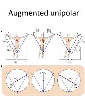
60 Unipolar Recordings Frank Norman Wilson ( ) investigated how electrocardiographic unipolar potentials could be defined. Ideally, those are measured with respect to a remote reference (infinity). But how is one to achieve this in the volume conductor of the size of the human body with electrodes already placed at the extremities? They suggested the use of the central terminal as this reference. This was formed by connecting a 5 kω resistor from each terminal of the limb leads to a common point called the central terminal.
61 The Wilson central terminal (CT) is formed by connecting a 5 k resistance to each limb electrode and interconnecting the free wires; the CT is the common point. The Wilson central terminal represents the average of the limb potentials. Because no current flows through a high-impedance voltmeter, Kirchhoff's law requires that I R + I L + I F = 0.
 The location of the Wilson central terminal in the image space (CT').")
62 (A) The circuit of the Wilson central terminal (CT). (B) The location of the Wilson central terminal in the image space (CT'). It is located in the center of the Einthoven triangle.
63 Wilson s Central Terminal VR + + VL + VF An equivalent reference electrode The average of the voltages on the three limb electrodes Minimize loading: Use three equal-valued resistors ( > 5 M-ohm ) Resulting electrode voltages are VL, VR, and VF
64 Simplified Electrocardiographic Recording System Electrodes Z 2 v ecg Z body Z 1 60-Hz ac magnetic field + V cc + Differential amplifier - v o Displacement currents -V cc Two possible interfering inputs are stray magnetic fields and capacitively coupled noise. Orientation of patient cables and changes in electrode-skin impedance are two possible modifying inputs. Z 1 and Z 2 represent the electrode-skin interface impedances.
65 Basic Biopotential Amplifier Requirements Purpose: To provide voltage and/or current gain to increase the amplitude of weak electric signals of biological origin Features: High input impedance (minimize the loading effects of the amplifier inputs) Protection circuitry (limit the possibility of introducing dangerous microshocks or macroshocks at the input terminals of the amplifier) Low output impedance (low with respect to the load being driven) Adequate output current (to supply the power needed to drive the load) Bandlimited frequency response (match the frequency response of the signal being measured to eliminate out-of-band noise) Quick calibration (include a signal source and a number of selectable fixed gains settings) High common-mode rejection for differential amplifiers (common mode signals are frequently larger than the biopotentials being measured) Additional specific requirements for each application
66 Generalized Static Characteristics of Instrumentation System Accuracy Difference between the true value and the measured value divided by the true value Precision Number of distinguishable alternatives (eg., a meter with a five digit readout) Resolution Smallest incremental quantity that can be measured with certainty Reproducibility Produces the same output for a given input over a period of time Statistical Control Systematic and bias error can be removed by calibration Random errors can be removed by taking multiple measurements and averaging the result.
67 Frequent Problems Frequency distortion High-frequency loss rounds the sharp edges of the QRS complex. Low-frequency loss can distort the baseline (no longer horizontal) or cause monophasic waveforms to appear biphasic. Saturation/cutoff distortion Combination of input amplitude & offset voltage drives amplifier into saturation Positive case: clips off the top of the R wave Negative case: clips off the Q, S, P and T waves Ground loops Patients are connected to multiple pieces of equipment; each has a ground (power line or common room ground wire) If more than one instrument has a ground electrode connected to the patient, a ground loop exists. Power line ground can be different for each item of equipment, sending current through the patient and introducing common-mode noise. Open lead wires Can be detected by impedance monitoring.
68 Artifacts Unwanted voltage transients Patient movement Electrical stimulation signals, like defibrillation Amplifier saturates First-order recovery to baseline Recovery time set by lowfrequency corner of the bandpass amplifier Effect of a voltage transient on an ECG recorded on an electrocardiograph in which the transient causes the amplifier to saturate, and a finite period of time is required for the charge to bleed off enough to bring the ECG back into the amplifier s active region of operation.
69 Artifacts Upper figure: coupling of 60 Hz power line noise Electric-field coupling between power grid, instrument, patient, and wiring. Lower figure: coupling of electromyographic (EMG) noise Example of tensing chest muscles while ECG is being recorded.
70 Power-Line Capacitive Coupling to body Power line is coupled into the body,small ac displacement current I db is generated, which produces a common mode voltage C b i db Power line 220 V Electrocardiograph v cm = i db Z G = (0.2 µa) (50 K W) = 10 mv At the amplifier inputs: suppose Z 2 Z 1 = 20k- W and Zin =5M- W v A - v B = v cm (Z 2 Z 1 )/ Z in = (10 mv) (20 KW / 5 MW) = 40 µv Remedies: Reduce or match the electrode skin impedances (minimize Z 1 - Z 2 ) Increase Z in u cm Z 2 u cm Z G i db u cm Z 1 Current flows from the power line through the body and ground impedance, thus creating a common-mode voltage everywhere on the body. Z in G Z in A B
71 Cure for power line capacitive coupling Easy cure: make Zg = 0, however it is not ALLOWED due to electric safety of the patient (short circuit prevention) Good Cure: Increase input impedance of the amplifier lowering skin-electrode impedance Driven Right Leg Circuit
72 Power-Line Coupling to cable and Amplifier Small parasitic capacitors connect the power line to the RA and LA leads, and the grounded instrument case and Small ac displacement currents I d1 and I d2 are generated The body impedance is about 500 W and can be neglected v A - v B = i d1 Z 1 - i d2 Z 2 If I d1 and I d2 are approximately equal: v A - v B = i d1 (Z 1 - Z 2 ) Remedies = (6 na) (20 K W) = 120 µv Shield electrodes to reduce i d Reduce or match the electrode skin impedances (minimize Z 1 - Z 2 ) Z 2 Z G Z 1 I d1+ I d2 Power line C 2 I d2 I d1 Electrocardiograph A mechanism of electric-field pickup of an electrocardiograph resulting from the power line. Coupling capacitance between live power line and lead wires causes current to flow through skin-electrode impedances on its way to ground. C 1 A B 220 V G C 3
73 Magnetic Field Coupling Magnetic-field pickup by the elctrocardiograph (a) Lead wires make a closed loop (shaded area) when patient and electrocardiograph are considered in the circuit. The change in magnetic field passing through this area induces a current in the loop. (b) This effect can be minimized by twisting the lead wires together and keeping them close to the body in order to subtend a much smaller area. Sources Power lines Transformers and ballasts in fluorescent lights Remedies Shielding Route leads away from potential sources twist the lead wires
74 Other Noise Sources Electromagnetic radiation Patient leads become antennas, especially if detached. Sources Radio Television Radar Research equipment Electrosurgical devices Arching fluorescent lights (needing replacement) Remedy Employ capacitors shunting the inputs to ground (eg., 200 pf). Do not lower the input impedance of the amplifier.
Biomedical Instrumentation (BME420 ) Chapter 6: Biopotential Amplifiers John G. Webster 4 th Edition
 Chapter 6: Biopotential Amplifiers John G. Webster 4 th Edition") Biomedical Instrumentation (BME420 ) Chapter 6: Biopotential Amplifiers John G. Webster 4 th Edition Dr. Qasem Qananwah BME 420 Department of Biomedical Systems and Informatics Engineering 1 Biopotential
Biomedical Instrumentation (BME420 ) Chapter 6: Biopotential Amplifiers John G. Webster 4 th Edition Dr. Qasem Qananwah BME 420 Department of Biomedical Systems and Informatics Engineering 1 Biopotential
Bio-Potential Amplifiers
 Bio-Potential Amplifiers Biomedical Models for Diagnosis Body Signal Sensor Signal Processing Output Diagnosis Body signals and sensors were covered in EE470 The signal processing part is in EE471 Bio-Potential
Lecture 4 Biopotential Amplifiers
 Bioinstrument Sahand University of Technology Lecture 4 Biopotential Amplifiers Dr. Shamekhi Summer 2016 OpAmp and Rules 1- A = (gain is infinity) 2- Vo = 0, when v1 = v2 (no offset voltage) 3- Rd = (input
Biomedical. Measurement and Design ELEC4623. Lectures 9 and 10 Practical biopotential amplifier design and multilead ECG systems
 Biomedical Instrumentation, Measurement and Design ELEC4623 Lectures 9 and 10 Practical biopotential amplifier design and multilead ECG systems Feedback and stability A negative feedback system with closed
Ques on (2): [18 Marks] a) Draw the atrial synchronous Pacemaker block diagram and explain its operation. Benha University June 2013
![Ques on (2): [18 Marks] a) Draw the atrial synchronous Pacemaker block diagram and explain its operation. Benha University June 2013](/thumbs/87/96832478.jpg "Ques on (2): [18 Marks] a) Draw the atrial synchronous Pacemaker block diagram and explain its operation. Benha University June 2013") Benha University June 2013 Benha Faculty of Engineering Electrical Department Hospital Instrumentations (E472) 4 Th year (control) Dr.Waleed Abdel Aziz Salem Time: 3 Hrs Answer the following questions.
Benha University June 2013 Benha Faculty of Engineering Electrical Department Hospital Instrumentations (E472) 4 Th year (control) Dr.Waleed Abdel Aziz Salem Time: 3 Hrs Answer the following questions.
Lab E5: Filters and Complex Impedance
 E5.1 Lab E5: Filters and Complex Impedance Note: It is strongly recommended that you complete lab E4: Capacitors and the RC Circuit before performing this experiment. Introduction Ohm s law, a well known
BIOMEDICAL INSTRUMENTATION PROBLEM SHEET 1
 BIOMEDICAL INSTRUMENTATION PROBLEM SHEET 1 Dr. Gari Clifford Hilary Term 2013 1. (Exemplar Finals Question) a) List the five vital signs which are most commonly recorded from patient monitors in high-risk
Kanchan S. Shrikhande. Department of Instrumentation Engineering, Vivekanand Education Society s Institute of.
 ISOLATED ECG AMPLIFIER WITH RIGHT LEG DRIVE Kanchan S. Shrikhande Department of Instrumentation Engineering, Vivekanand Education Society s Institute of Technology(VESIT),kanchans90@gmail.com Abstract
Changing the sampling rate
 Noise Lecture 3 Finally you should be aware of the Nyquist rate when you re designing systems. First of all you must know your system and the limitations, e.g. decreasing sampling rate in the speech transfer
Amplificador de Biopotencial
 Amplificador de Biopotencial Prof. Sérgio F. Pichorim Baseado no cap 6 do Webster e cap 17 do Kutz & Towe From J. G. Webster (ed.), Medical instrumentation: application and design. 3 rd ed. New York: John
ECG Project. Raphal Blanchet, Axel Boland, Thomas Donnay, Mario Jose Teles Varandas, University of Liege
 ECG Project Raphal Blanchet, Axel Boland, Thomas Donnay, Mario Jose Teles Varandas, University of Liege Abstract We were asked to design our own Electrocardiogram. Obviously, recording heart beats without
Crossover Distortion (hole) Amplifier Classification. Amplifiers: Class A, B, AB, D Op-amp Application: ECG. Why is [b] better? - LF356 - LF
![Crossover Distortion (hole) Amplifier Classification. Amplifiers: Class A, B, AB, D Op-amp Application: ECG. Why is [b] better? - LF356 - LF](/thumbs/91/105246691.jpg "Crossover Distortion (hole) Amplifier Classification. Amplifiers: Class A, B, AB, D Op-amp Application: ECG. Why is [b] better? - LF356 - LF") Crossover Distortion (hole) 10kΩ Amplifiers: Class A, B, AB, D Op-amp Application: ECG v in 10kΩ 2 3 10kΩ 0.1µF - LF356 + 0.1µF?kΩ [a] +15 7 6 4-15 2N3906 +15 10kΩ 2N3904 v out R L v in -15 2 3 - LF356
Crossover Distortion (hole) 10kΩ Amplifiers: Class A, B, AB, D Op-amp Application: ECG v in 10kΩ 2 3 10kΩ 0.1µF - LF356 + 0.1µF?kΩ [a] +15 7 6 4-15 2N3906 +15 10kΩ 2N3904 v out R L v in -15 2 3 - LF356
Special-Purpose Operational Amplifier Circuits
 Special-Purpose Operational Amplifier Circuits Instrumentation Amplifier An instrumentation amplifier (IA) is a differential voltagegain device that amplifies the difference between the voltages existing
EXPERIMENT 8 Bio-Electric Measurements
 EXPERIMENT 8 Bio-Electric Measurements Objectives 1) Determine the amplitude of some electrical signals in the body. 2) Observe and measure the characteristics and amplitudes of muscle potentials due to
IMPROVEMENTS IN ELECTROCARDIOGRAPHY SMOOTHENING AND AMPLIFICATION
 IMPROVEMENTS IN ELECTROCARDIOGRAPHY SMOOTHENING AND AMPLIFICATION Manan Joshi, Sarosh Patel, Dr. Lawrence Hmurcik Electrical Engineering Department University of Bridgeport Bridgeport, CT 06604 Abstract
ECG Set. We Simplify the Procedures and You Save Time!
 ECG Set We Simplify the Procedures and You Save Time! WhaleTeq ECG Set Standard coverage: IEC 6060--5, --7, --47, AAMI/ANSI EC, EC, EC8, EC57, YY079, YY9, YY078, etc. Adopted by International Certification
EXPERIMENT 5 Bioelectric Measurements
 Objectives EXPERIMENT 5 Bioelectric Measurements 1) Generate periodic signals with a Signal Generator and display on an Oscilloscope. 2) Investigate a Differential Amplifier to see small signals in a noisy
Development of Electrocardiograph Monitoring System
 Development of Electrocardiograph Monitoring System Khairul Affendi Rosli 1*, Mohd. Hafizi Omar 1, Ahmad Fariz Hasan 1, Khairil Syahmi Musa 1, Mohd Fairuz Muhamad Fadzil 1, and Shu Hwei Neu 1 1 Department
BME 405 BIOMEDICAL ENGINEERING SENIOR DESIGN 1 Fall 2005 BME Design Mini-Project Project Title
 BME 405 BIOMEDICAL ENGINEERING SENIOR DESIGN 1 Fall 2005 BME Design Mini-Project Project Title Basic system for Electrocardiography Customer/Clinical need A recent health care analysis have demonstrated
TRANSDUCER INTERFACE APPLICATIONS
 TRANSDUCER INTERFACE APPLICATIONS Instrumentation amplifiers have long been used as preamplifiers in transducer applications. High quality transducers typically provide a highly linear output, but at a
E40M. Instrumentation Amps and Noise. M. Horowitz, J. Plummer, R. Howe 1
 E40M Instrumentation Amps and Noise M. Horowitz, J. Plummer, R. Howe 1 ECG Lab - Electrical Picture Signal amplitude 1 mv Noise level will be significant will need to amplify and filter We ll use filtering
GBM8320 Dispositifs Médicaux Intelligents
 GBM8320 Dispositifs Médicaux Intelligents Biopotential amplifiers Part 1 Mohamad Sawan et al. Laboratoire de neurotechnologies Polystim http://www.cours.polymtl.ca/gbm8320/ mohamad.sawan@polymtl.ca M5418
Used to overcome ventricular fibrillation may be due to coronary occlusion, shock, or abnormalities in blood chemistry
 Used to overcome ventricular fibrillation may be due to coronary occlusion, shock, or abnormalities in blood chemistry Main problem: heart muscle fibers are continuously stimulated by adjacent muscles
EE 230 Experiment 10 ECG Measurements Spring 2010
 EE 230 Experiment 10 ECG Measurements Spring 2010 Note: If for any reason the students are uncomfortable with doing this experiment, please talk to the instructor for the course and an alternative experiment
Biopotential Amplifiers. Hsiao-Lung Chan, Ph.D. Dept Electrical Engineering Chang Gung University, Taiwan
 Biopotential Ampliiers Hsiao-Lung Chan, Ph.D. Dept Electrical Engineering Chang Gung University, Taiwan chanhl@mail.cgu.edu.tw Operational ampliier Practical Ideal Biopotential ampliiers Ideal vs. practical
EECE Circuits and Signals: Biomedical Applications. Lab ECG I The Instrumentation Amplifier
 EECE 150 - Circuits and Signals: Biomedical Applications Lab ECG I The Instrumentation Amplifier Introduction: As discussed in class, instrumentation amplifiers are often used to reject common-mode signals
Design on Electrocardiosignal Detection Sensor
 Sensors & Transducers 203 by IFSA http://www.sensorsportal.com Design on Electrocardiosignal Detection Sensor Hao ZHANG School of Mathematics and Computer Science, Tongling University, 24406, China E-mail:
Homework Assignment True or false. For both the inverting and noninverting op-amp configurations, V OS results in
 Question 1 (Short Takes), 2 points each. Homework Assignment 02 1. An op-amp has input bias current I B = 1 μa. Make an estimate for the input offset current I OS. Answer. I OS is normally an order of
CHAPTER 7 INTERFERENCE CANCELLATION IN EMG SIGNAL
 131 CHAPTER 7 INTERFERENCE CANCELLATION IN EMG SIGNAL 7.1 INTRODUCTION Electromyogram (EMG) is the electrical activity of the activated motor units in muscle. The EMG signal resembles a zero mean random
University of Pennsylvania Moore School of Electrical Engineering ESE319 Electronic Circuits - Modeling and Measurement Techniques
 University of Pennsylvania Moore School of Electrical Engineering ESE319 Electronic Circuits - Modeling and Measurement Techniques 1. Introduction. Students are often frustrated in their attempts to execute
Biomedical Engineering Electrophysiology
 Biomedical Engineering Electrophysiology Dr. rer. nat. Andreas Neubauer Sources of biological potentials and how to record them 1. How are signals transmitted along nerves? Transmit velocity Direction
EUA2011A. Low EMI, Ultra-Low Distortion, 2.5-W Mono Filterless Class-D Audio Power Amplifier DESCRIPTION FEATURES APPLICATIONS
 Low EMI, Ultra-Low Distortion, 2.5-W Mono Filterless Class-D Audio Power Amplifier DESCRIPTION The EUA2011A is a high efficiency, 2.5W mono class-d audio power amplifier. A new developed filterless PWM
Device Interconnection
 Device Interconnection An important, if less than glamorous, aspect of audio signal handling is the connection of one device to another. Of course, a primary concern is the matching of signal levels and
Electrical noise in the OR
 Electrical noise in the OR Chris Thompson Senior Staff Specialist Royal Prince Alfred Hospital SYDNEY SOUTH WEST AREA HEALTH SERVICE NSW HEALTH Electrical noise in the OR Root causes Tiny little signals
BME 701 Lecture 1. Measurement and Instrumentation
 BME 701 Lecture 1 Measurement and Instrumentation 1 Cochlear Implant 2 Advances in Vision (Retinal Stimulation) 3 Mini Gastric Imaging 4 5 Aspects of Measurement General Instrumentation Transducers (Electrodes)
 Page 1 of 6 A Historical Perspective From Aristotle to Hawking Force & Its Effects Measurement Limitations The Strain Gage Sensor Designs Measuring Circuits Application & Installation Process Pressure
Laboratory Project 1: Design of a Myogram Circuit
 1270 Laboratory Project 1: Design of a Myogram Circuit Abstract-You will design and build a circuit to measure the small voltages generated by your biceps muscle. Using your circuit and an oscilloscope,
Name Kyla Jackson, Todd Germeroth, Jake Spooler Date May 5, 2010 Lab 3E Group 3 Experiment Title Project Deliverable 3
 Name Kyla Jackson, Todd Germeroth, Jake Spooler Date May 5, 2010 Lab 3E Group 3 Experiment Title Project Deliverable 3 Objective The objective of this project was to design and construct an ECG measurement
HUMAN DETECTION AND RESCUE USING BIO POTENTIAL SIGNALS
 ISET GOLDEN JUBILEE SYMPOSIUM Indian Society of Earthquake Technology Department of Earthquake Engineering Building IIT Roorkee, Roorkee October 20-21, 2012 Paper No. A007 HUMAN DETECTION AND RESCUE USING
Today s menu. Last lecture. Series mode interference. Noise and interferences R/2 V SM Z L. E Th R/2. Voltage transmission system
 Last lecture Introduction to statistics s? Random? Deterministic? Probability density functions and probabilities? Properties of random signals. Today s menu Effects of noise and interferences in measurement
EUA W Mono Filterless Class-D Audio Power Amplifier DESCRIPTION FEATURES APPLICATIONS. Typical Application Circuit
 3-W Mono Filterless Class-D Audio Power Amplifier DESCRIPTION The EUA2011 is a high efficiency, 3W mono class-d audio power amplifier. A low noise, filterless PWM architecture eliminates the output filter,
Testing Power Sources for Stability
 Keywords Venable, frequency response analyzer, oscillator, power source, stability testing, feedback loop, error amplifier compensation, impedance, output voltage, transfer function, gain crossover, bode
Indigenous Design of Electronic Circuit for Electrocardiograph
 Indigenous Design of Electronic Circuit for Electrocardiograph Raman Gupta 1, Sandeep Singh 2, Kashish Garg 3, Shruti Jain 4 U.G student, Department of Electronics and Communication Engineering,Jaypee
EDL Group #3 Final Report - Surface Electromyograph System
 EDL Group #3 Final Report - Surface Electromyograph System Group Members: Aakash Patil (07D07021), Jay Parikh (07D07019) INTRODUCTION The EMG signal measures electrical currents generated in muscles during
instead we hook it up to a potential difference of 60 V? instead we hook it up to a potential difference of 240 V?
 Introduction In this lab we will examine the concepts of electric current and potential in a circuit. We first look at devices (like batteries) that are used to generate electrical energy that we can use
Four-Channel Differential AC Amplifier
 Four-Channel Differential AC Amplifier INSTRUCTION MANUAL FOR HIGH-GAIN DIFFERENTIAL AMPLIFIER MODEL 1700 Serial # Date A-M Systems, Inc. PO Box 850 Carlsborg, WA 98324 U.S.A. 360-683-8300 800-426-1306
BENG 186B Winter 2012 Quiz 3. March 7, NAME (Last, First): This quiz is closed book and closed note. You may use a calculator for algebra.
: This quiz is closed book and closed note. You may use a calculator for algebra.") BENG 186B Winter 2012 Quiz 3 March 7, 2012 NAME (Last, First): This quiz is closed book and closed note. You may use a calculator for algebra. Circle your final answers in the space provided; show your
BENG 186B Winter 2012 Quiz 3 March 7, 2012 NAME (Last, First): This quiz is closed book and closed note. You may use a calculator for algebra. Circle your final answers in the space provided; show your
THE AMPLIFIER. A-B = C subtractor. INPUTS Figure 1
 OBJECTIVES: THE AMPLIFIER 1) Explain the operation of the differential amplifier. 2) Determine the gain of each side of the differential amplifier. 3) Determine the gain of the differential amplifier as
WHALETEQ Common Mode Rejection Ratio Tester (CMRR 3.0) User Manual (Revision )
 User Manual (Revision )") WHALETEQ Common Mode Rejection Ratio Tester (CMRR 3.0) User Manual (Revision 2017-10-06) Copyright (c) 2013-2017, All Rights Reserved. WhaleTeq Co. LTD No part of this publication may be reproduced, transmitted,
WHALETEQ Common Mode Rejection Ratio Tester (CMRR 3.0) User Manual (Revision 2017-10-06) Copyright (c) 2013-2017, All Rights Reserved. WhaleTeq Co. LTD No part of this publication may be reproduced, transmitted,
SIGNAL RECOVERY: Sensors, Signals, Noise and Information Recovery
 SIGNAL RECOVERY: Sensors, Signals, Noise and Information Recovery http://home.deib.polimi.it/cova/ 1 Signal Recovery COURSE OUTLINE Scenery preview: typical examples and problems of Sensors and Signal
Medlab GmbH EG04000 User Manual. medlab. Four Lead ECG OEM board EG Technical Manual. Copyright Medlab Version Version 1.
 Medlab GmbH EG04000 User Manual medlab Four Lead ECG OEM board EG04000 Technical Manual Copyright Medlab 2014 1 Medlab GmbH EG04000 User Manual Medlab medizinische Diagnosegeräte GmbH Helmholtzstrasse
AD8232 EVALUATION BOARD DOCUMENTATION
 One Technology Way P.O. Box 9106 Norwood, MA 02062-9106 Tel: 781.329.4700 Fax: 781.461.3113 www.analog.com AD8232 EVALUATION BOARD DOCUMENTATION FEATURES Ready to use Heart Rate Monitor (HRM) Front end
Operating and Maintenance Instructions. Harvard Isolated Preamplifier
 84 October Hill Road Massachusetts 01746 Tel.: (508) 893-8999 Fax: (508) 429-5732 e-mail: bioscience @harvardapparatus.com Web Site: harvardapparatus.com Operating and Maintenance Instructions Harvard
ARIC Data Book Page 1 of 13 Cohort, Exam 4 ECG data: FORM CODE=ECG VERSION=E
 Page 1 of 13 ECG data: FORM CODE=ECG VERSION=E Coded - machine ECGE01 ECG tech code 11594 Present Text suppressed 35 Missing ECGE02 ECGsent - same as ECGE57 8606 0 No 2990 1 Yes ECGE04 Filter setting -
CONNECTING THE PROBE TO THE TEST INSTRUMENT
 2SHUDWLRQ 2SHUDWLRQ Caution The input circuits in the AP034 Active Differential Probe incorporate components that protect the probe from damage resulting from electrostatic discharge (ESD). Keep in mind
EE 241 Experiment #4: USE OF BASIC ELECTRONIC MEASURING INSTRUMENTS, Part III 1
 EE 241 Experiment #4: USE OF BASIC ELECTRONIC MEASURING INSTRUMENTS, Part III 1 PURPOSE: To become familiar with more of the instruments in the laboratory. To become aware of operating limitations of input
55:041 Electronic Circuits The University of Iowa Fall Exam 3. Question 1 Unless stated otherwise, each question below is 1 point.
 Exam 3 Name: Score /65 Question 1 Unless stated otherwise, each question below is 1 point. 1. An engineer designs a class-ab amplifier to deliver 2 W (sinusoidal) signal power to an resistive load. Ignoring
UNIVERSITY OF UTAH ELECTRICAL AND COMPUTER ENGINEERING DEPARTMENT ELECTROMYOGRAM (EMG) DETECTOR WITH AUDIOVISUAL OUTPUT
 DETECTOR WITH AUDIOVISUAL OUTPUT") UNIVESITY OF UTAH ELECTICAL AND COMPUTE ENGINEEING DEPATMENT ECE 3110 LABOATOY EXPEIMENT NO. 5 ELECTOMYOGAM (EMG) DETECTO WITH AUDIOVISUAL OUTPUT Pre-Lab Assignment: ead and review Sections 2.4, 2.8.2,
UNIVESITY OF UTAH ELECTICAL AND COMPUTE ENGINEEING DEPATMENT ECE 3110 LABOATOY EXPEIMENT NO. 5 ELECTOMYOGAM (EMG) DETECTO WITH AUDIOVISUAL OUTPUT Pre-Lab Assignment: ead and review Sections 2.4, 2.8.2,
ECE 480 Design Team 6 Electrocardiography and Design
 ECE 480 Design Team 6 Electrocardiography and Design Alex Volinski November 16 th, 2012 Executive Summary Recently there has been a large increase in consumer demand for a new and functional ECG (Electrocardiograph)
EG medlab. Three Lead ECG OEM board. Version Technical Manual. Medlab GmbH Three Lead ECG OEM Module EG01010 User Manual
 Medlab GmbH Three Lead ECG OEM Module EG01010 User Manual medlab Three Lead ECG OEM board EG01010 Technical Manual Copyright Medlab 2008-2016 Version 1.03 1 Version 1.03 28.04.2016 Medlab GmbH Three Lead
Precision INSTRUMENTATION AMPLIFIER
 Precision INSTRUMENTATION AMPLIFIER FEATURES LOW OFFSET VOLTAGE: µv max LOW DRIFT:.µV/ C max LOW INPUT BIAS CURRENT: na max HIGH COMMON-MODE REJECTION: db min INPUT OVER-VOLTAGE PROTECTION: ±V WIDE SUPPLY
EXPERIMENT 7 The Amplifier
 Objectives EXPERIMENT 7 The Amplifier 1) Understand the operation of the differential amplifier. 2) Determine the gain of each side of the differential amplifier. 3) Determine the gain of the differential
PRODUCT SHEET IMPORTANT SAFETY NOTES!
 STMISO STIMULUS ISOLATION ADAPTERS See also: Stimulator Setup notes in AcqKnowledge Software Guide BIOPAC offers three stimulus isolation adapters: STMISOC constant current or constant voltage (5X / 10X)
Signal and Noise Measurement Techniques Using Magnetic Field Probes
 Signal and Noise Measurement Techniques Using Magnetic Field Probes Abstract: Magnetic loops have long been used by EMC personnel to sniff out sources of emissions in circuits and equipment. Additional
Experiment 1: Instrument Familiarization (8/28/06)
") Electrical Measurement Issues Experiment 1: Instrument Familiarization (8/28/06) Electrical measurements are only as meaningful as the quality of the measurement techniques and the instrumentation applied
Electrical Measurement Issues Experiment 1: Instrument Familiarization (8/28/06) Electrical measurements are only as meaningful as the quality of the measurement techniques and the instrumentation applied
Homework Assignment 03
 Homework Assignment 03 Question 1 (Short Takes), 2 points each unless otherwise noted. 1. Two 0.68 μf capacitors are connected in series across a 10 khz sine wave signal source. The total capacitive reactance
Lab #9: Compound Action Potentials in the Toad Sciatic Nerve
 Lab #9: Compound Action Potentials in the Toad Sciatic Nerve In this experiment, you will measure compound action potentials (CAPs) from an isolated toad sciatic nerve to illustrate the basic physiological
UNIT - 1 OPERATIONAL AMPLIFIER FUNDAMENTALS
 UNIT - 1 OPERATIONAL AMPLIFIER FUNDAMENTALS 1.1 Basic operational amplifier circuit- hte basic circuit of an operational amplifier is as shown in above fig. has a differential amplifier input stage and
Laboratory Project 1B: Electromyogram Circuit
 2240 Laboratory Project 1B: Electromyogram Circuit N. E. Cotter, D. Christensen, and K. Furse Electrical and Computer Engineering Department University of Utah Salt Lake City, UT 84112 Abstract-You will
INSTITUTE OF AERONAUTICAL ENGINEERING (Autonomous) Dundigal, Hyderabad
 Dundigal, Hyderabad") I INSTITUTE OF AERONAUTICAL ENGINEERING (Autonomous) Dundigal, Hyderabad-500043 CIVIL ENGINEERING TUTORIAL QUESTION BANK Course Name : BASIC ELECTRICAL AND ELECTRONICS ENGINEERING Course Code : AEE018
I INSTITUTE OF AERONAUTICAL ENGINEERING (Autonomous) Dundigal, Hyderabad-500043 CIVIL ENGINEERING TUTORIAL QUESTION BANK Course Name : BASIC ELECTRICAL AND ELECTRONICS ENGINEERING Course Code : AEE018
* Notebook is excluded. Features KL-720 contains nine modules, including Electrocardiogram Measurement, E lectromyogram Measurement,
 KL-720 Biomedical Measurement System Supplied by: 011 683 4365 This equipment is intended for students to learn how to design specific measuring circuits and detect the basic physiological signals with
EMG Electrodes. Fig. 1. System for measuring an electromyogram.
 1270 LABORATORY PROJECT NO. 1 DESIGN OF A MYOGRAM CIRCUIT 1. INTRODUCTION 1.1. Electromyograms The gross muscle groups (e.g., biceps) in the human body are actually composed of a large number of parallel
ARIC Data Book. Cohort, Exam 4. ECG data. Composite, with adjudications Present Text suppressed. 35 Missing. Filter setting - not used - blank
 Page 1 of 12 ECG data Composite, with adjudications ECGMD01 ECG tech code 11594 Present Text suppressed 35 Missing ECGMD04 Filter setting - not used - blank 11629 Missing ECGMD05 Cart code 2 00 2836 01
Investigation of a Voltage Probe in Microstrip Technology
 Investigation of a Voltage Probe in Microstrip Technology (Specifically in 7-tesla MRI System) By : Mona ParsaMoghadam Supervisor : Prof. Dr. Ing- Klaus Solbach April 2015 Introduction - Thesis work scope
ES250: Electrical Science. HW6: The Operational Amplifier
 ES250: Electrical Science HW6: The Operational Amplifier Introduction This chapter introduces the operational amplifier or op amp We will learn how to analyze and design circuits that contain op amps,
Biomedical Instrumentation B2. Dealing with noise
 Biomedical Instrumentation B2. Dealing with noise B18/BME2 Dr Gari Clifford Noise & artifact in biomedical signals Ambient / power line interference: 50 ±0.2 Hz mains noise (or 60 Hz in many data sets)
Experiment 1: Instrument Familiarization
 Electrical Measurement Issues Experiment 1: Instrument Familiarization Electrical measurements are only as meaningful as the quality of the measurement techniques and the instrumentation applied to the
Chapter 12: Transmission Lines. EET-223: RF Communication Circuits Walter Lara
 Chapter 12: Transmission Lines EET-223: RF Communication Circuits Walter Lara Introduction A transmission line can be defined as the conductive connections between system elements that carry signal power.
4. Digital Measurement of Electrical Quantities
 4.1. Concept of Digital Systems Concept A digital system is a combination of devices designed for manipulating physical quantities or information represented in digital from, i.e. they can take only discrete
INSTRUCTION MANUAL FOR MICROELECTRODE AC AMPLIFIER MODEL 1800
 INSTRUCTION MANUAL FOR MICROELECTRODE AC AMPLIFIER MODEL 1800 Serial # Date, Inc. PO Box 850 Carlsborg, WA 98324 U.S.A. 360-683-8300 800-426-1306 FAX: 360-683-3525 http://www.a-msystems.com Version 9.0
electronics fundamentals
 electronics fundamentals circuits, devices, and applications THOMAS L. FLOYD DAVID M. BUCHLA chapter 6 Identifying series-parallel relationships Most practical circuits have combinations of series and
Analog Circuits and Systems
 Analog Circuits and Systems Prof. K Radhakrishna Rao Lecture 3 Role of Analog Signal Processing in Electronic Products Part 11 1 Cell Phone o The most dominant product of present day world o Its basic
This is an outline of the subjects that will be touched upon during this presentation.
 Welcome to A Precision Low-Level DAS/ECG Cardio tachometer Demo board presentation. The presentation will focus on an interesting application of analog circuits where they are utilized to amplify and condition
Glossary 78 LIFETIME LIMITED WARRANTY. GREENLEE Phone: (International)
") A AC alternating current, or current that reverses direction at regular rate. When graphed, alternating current can appear as a series of curves, squares, or triangles. The shape of the graph is referred
A AC alternating current, or current that reverses direction at regular rate. When graphed, alternating current can appear as a series of curves, squares, or triangles. The shape of the graph is referred
Differential-Mode Emissions
 Differential-Mode Emissions In Fig. 13-5, the primary purpose of the capacitor C F, however, is to filter the full-wave rectified ac line voltage. The filter capacitor is therefore a large-value, high-voltage
A PC Based Cost Effective Advanced Cardio Signals Monitoring System
 Biomedical Statistics and Informatics 2017; 2(6): 150-161 http://www.sciencepublishinggroup.com/j/bsi doi: 10.11648/j.bsi.20170206.11 Report A PC Based Cost Effective Advanced Cardio Signals Monitoring
Medlab GmbH EG05000 User Manual. medlab. Five Lead ECG OEM board EG Technical Manual. Copyright Medlab Version Version 1.
 Medlab GmbH EG05000 User Manual medlab Five Lead ECG OEM board EG05000 Technical Manual Copyright Medlab 2016 1 Medlab GmbH EG05000 User Manual Medlab GmbH support@medlab.eu www.medlab.eu 2 Medlab GmbH
Introduction to Biomedical Engineering
 Introduction to Biomedical Engineering Biomedical Instrumentation Kung-Bin Sung 5/8/007 Outline Chapter 8 and chapter 5 of st edition: Bioinstrumentation Bridge circuit Operational amplifiers, instrumentation
Power Electronics. Exercise: Circuit Feedback
 Lehrstuhl für Elektrische Antriebssysteme und Leistungselektronik Technische Universität München Prof Dr-Ing Ralph Kennel Aricsstr 21 Email: eat@eitumde Tel: +49 (0)89 289-28358 D-80333 München Internet:
Chapter 33. Alternating Current Circuits
 Chapter 33 Alternating Current Circuits C HAP T E O UTLI N E 33 1 AC Sources 33 2 esistors in an AC Circuit 33 3 Inductors in an AC Circuit 33 4 Capacitors in an AC Circuit 33 5 The L Series Circuit 33
(i) Determine the admittance parameters of the network of Fig 1 (f) and draw its - equivalent circuit.
 Determine the admittance parameters of the network of Fig 1 (f) and draw its - equivalent circuit.") I.E.S-(Conv.)-1995 ELECTRONICS AND TELECOMMUNICATION ENGINEERING PAPER - I Some useful data: Electron charge: 1.6 10 19 Coulomb Free space permeability: 4 10 7 H/m Free space permittivity: 8.85 pf/m Velocity
I.E.S-(Conv.)-1995 ELECTRONICS AND TELECOMMUNICATION ENGINEERING PAPER - I Some useful data: Electron charge: 1.6 10 19 Coulomb Free space permeability: 4 10 7 H/m Free space permittivity: 8.85 pf/m Velocity
Questions Bank of Electrical Circuits
 Questions Bank of Electrical Circuits 1. If a 100 resistor and a 60 XL are in series with a 115V applied voltage, what is the circuit impedance? 2. A 50 XC and a 60 resistance are in series across a 110V
Chapter 4 4. Optoelectronic Acquisition System Design
 4. Optoelectronic Acquisition System Design The present chapter deals with the design of the optoelectronic (OE) system required to translate the obtained optical modulated signal with the photonic acquisition
*Notebook is excluded
 Biomedical Measurement Training System This equipment is designed for students to learn how to design specific measuring circuits and detect the basic physiological signals with practical operation. Moreover,
DUAL ULTRA MICROPOWER RAIL-TO-RAIL CMOS OPERATIONAL AMPLIFIER
 ADVANCED LINEAR DEVICES, INC. ALD276A/ALD276B ALD276 DUAL ULTRA MICROPOWER RAILTORAIL CMOS OPERATIONAL AMPLIFIER GENERAL DESCRIPTION The ALD276 is a dual monolithic CMOS micropower high slewrate operational
Development of an alternative method for the calibration of ECG simulators
 Development of an alternative method for the calibration of ECG simulators Roberto Benitez 1,, Romi Uresti 2,, and Carolina Solorzano 3, 1 ETALONS, S.A. de C.V., 64640 Monterrey, Mexico Abstract. In Mexico,
OPERATING INSTRUCTIONS AND SYSTEM DESCRIPTION FOR THE. ISO-STIM 01D STIMULUS ISOLATION UNIT ±100 V / ±10 ma, bipolar output
 OPERATING INSTRUCTIONS AND SYSTEM DESCRIPTION FOR THE ISO-STIM 01D STIMULUS ISOLATION UNIT ±100 V / ±10 ma, bipolar output VERSION 4.0 npi 2014 npi electronic GmbH, Bauhofring 16, D-71732 Tamm, Germany
BENG 186B Winter 2013 Final
 Name (Last, First): BENG 186B Winter 2013 Final This exam is closed book, closed note, calculators are OK. Circle and put your final answers in the space provided; show your work only on the pages provided.
ECE4902 C Lab 7
 ECE902 C2012 - Lab MOSFET Differential Amplifier Resistive Load Active Load PURPOSE: The primary purpose of this lab is to measure the performance of the differential amplifier. This is an important topology
UNIT- IV ELECTRONICS
 UNIT- IV ELECTRONICS INTRODUCTION An operational amplifier or OP-AMP is a DC-coupled voltage amplifier with a very high voltage gain. Op-amp is basically a multistage amplifier in which a number of amplifier