Motus Reference Manual
|
|
|
- Amie Freeman
- 5 years ago
- Views:
Transcription


1
2 Page of Version. 7//6 Table of Contents 5 Revision History... Firmware Changelog... 9 Hardware Changelog... Introduction... Foundation Knowledge GNSS INS GNSS/INS AHRS The Sensor Co-ordinate Frame Roll, Pitch and Heading Second Right Hand Rule Rotation Order Geodetic Co-ordinate System NED Co-ordinate Frame ECEF Co-ordinate Frame Rugged Evaluation Kit Kit Contents Quick Start... 7 OEM Evaluation Kit Kit Contents Quick Start... 9 Part Numbers and Ordering Options.... Evaluation Kit.... Standalone Unit.... Software License Upgrades.... Accessories... 9 Specifications Mechanical Drawings Navigation Specifications Sensor Specifications Rugged Communication Specifications OEM Communication Specifications Rugged Hardware Specifications OEM Hardware Specifications Rugged Electrical Specifications OEM Electrical Specifications Power Consumption Rugged Connector Pin-out Rugged Evaluation Kit USB Cable Rugged Optional Breakout Cable Serial Number... Installation.... Installation Checklist.... Position and Alignment..... Alignment.... Mounting Plate Power Supply... 5
3 Page of Version. 7//6.5 Vibration... 6 INS and AHRS Operation Initialisation Orientation Initialisation Navigation Initialisation Heading Initialisation..... Time Initialisation.... Hot Start.... Time Heading Source Magnetic Heading Velocity Heading External Heading Magnetics D Magnetic Calibration Using the Motus Manager Software Using the Packet Protocol D Magnetic Calibration Using the Motus Manager Software Using the Packet Protocol Automatic Magnetic Calibration Disabling Magnetometers....6 Data Anti Aliasing....7 Vehicle Profiles.... Odometer Pulse Length..... Odometer Automatic Pulse Length Calibration Procedure....9 Reversing Detection.... Motion Analysis.... Heave.... Environmental Exposure..... Temperature..... Water..... Salt..... Dirt and Dust PH Level Shocks... 5 Motus Manager Software Changelog System Requirements Installation Troubleshooting All Platforms Windows Linux....5 Main View Serial Port Attitude Indicator Status Indicator Motus Status Indicator Fix Indicator... 5
4 Page of Version. 7//6.5.. Satellites Table D Map D Map Controls Reset View Clear History Logging Views Device Information Status Satellites Raw Sensors Orientation Position Velocity and Acceleration D Model Communications Statistics Heave Configuration Configuration Export Filter Options Packet Rates Alignment Configuration Alignment Offset GNSS Antenna Offset Odometer Offset External Data Offset Baud Rates GPIO Configuration Odometer Reset Heave Offset GPIO Output Manual Initialisation Tools Terminal Magnetic Calibration Firmware Update Log Converter Network Connect... 7 OEM Integration OEM PCB Mechanical Mounting...7. OEM Electrical Connector Interoperability with Different Voltage Systems Reset Line Basic Connection Recommended Footprint OEM Power Supply OEM Pin Protection OEM Development Board.... Serial UART to USB Converter...
5 Page of Version. 7//6. Dual RS Transceiver.... GPIO Header and Status LEDs.... Configuration Switches..... Primary Serial Port to USB..... Primary Serial Port to RS and GPIO & to RS..... Primary Serial Port and GPIO & to GPIO Header at TTL levels....5 Power source Schematics Interfacing Communication Baud Rate External Data GPIO Pins and Auxiliary RS GPIO Pins Voltage Level GNSS RS Dynamic Pin Functions PPS Output GNSS Fix Output Odometer Input Zero Velocity Input Pitot Tube Input NMEA Input NMEA Output Novatel GNSS Input Topcon GNSS Input ANPP Input ANPP Output Disable GNSS Disable Pressure Set Zero Orientation Alignment System State Packet Trigger Raw Sensors Packet Trigger RTCM Differential GNSS Corrections Input Trimble GNSS Input u-blox GNSS Input Hemisphere GNSS Input Left Wheel Speed Sensor Right Wheel Speed Sensor PPS Input Wheel Speed Sensor Wheel Encoder Phase A Wheel Encoder Phase B Event Input Event Input TSS Output Simrad Output Simrad Output Serial Port Passthrough Gimbal Encoder Phase A Gimbal Encoder Phase B...95
6 Page 5 of Version. 7// Odometer Direction, Forward Low Odometer Direction, Forward High Advanced Navigation Packet Protocol Data Types Packet Structure Header LRC Packet ID Packet Length CRC Packet Requests Packet Acknowledgement Packet Rates Packet Timing Packet Summary System Packets Acknowledge Packet Acknowledge Result Request Packet Boot Mode Packet Boot Mode Types Device Information Packet Restore Factory Settings Packet Reset Packet Verification Sequence Values Serial Port Pass-through Packet Pass-through Routes State Packets System State Packet System Status Filter Status GNSS Fix Status Unix Time Seconds Microseconds Unix Time Packet Formatted Time Packet Status Packet Position Standard Deviation Packet Velocity Standard Deviation Packet Euler Orientation Standard Deviation Packet Quaternion Orientation Standard Deviation Packet Raw Sensors Packet Raw GNSS Packet Raw GNSS Status Satellites Packet Detailed Satellites Packet Satellite Systems Satellite Frequencies Geodetic Position Packet ECEF Position Packet UTM Position Packet... 6
7 Page 6 of Version. 7// NED Velocity Packet Body Velocity Packet Acceleration Packet Body Acceleration Packet Euler Orientation Packet Quaternion Orientation Packet DCM Orientation Packet Angular Velocity Packet Angular Acceleration Packet External Position & Velocity Packet External Position Packet External Velocity Packet External Body Velocity Packet External Heading Packet Running Time Packet Local Magnetic Field Packet Odometer State Packet External Time Packet External Depth Packet Geoid Height Packet External Pitot Pressure Packet Wind Packet Heave Packet Post Processing Packet External Odometer Packet Odometer flags External Air Data Packet External Air Data Flags Notes Gimbal State Packet Automotive Packet Configuration Packets Packet Timer Period Packet UTC Synchronisation Packet Timer Period Packets Period Packet Clear Existing Packets Packet Period Baud Rates Packet Installation Alignment Packet Alignment DCM Filter Options Packet Vehicle Types Advanced Filter Parameters Packet GPIO Configuration Packet GPIO Functions GPIO Functions Auxiliary RS Transmit Functions Auxiliary RS Receive Functions Magnetic Calibration Values Packet...7
8 Page 7 of Version. 7// Magnetic Calibration Configuration Packet Magnetic Calibration Actions Magnetic Calibration Status Packet Magnetic Calibration Status Odometer Configuration Packet Set Zero Orientation Alignment Packet Reference Point Offsets Packet GPIO Output Configuration Packet NMEA Fix Behaviour GPIO Output Rates GPIO Output Rates Index User Data Packet GPIO Input Configuration Packet...
9 Page of Version. 7//6 Revision History Version Date. 7//6 Table : Revision history Changes Initial Release
10 Page 9 of Version. 7//6 Firmware Changelog Version Date. //6 Table : Firmware changelog Changes Initial release
11 Page of Version. 7//6 Hardware Changelog Version Date. /9/5 Table : Hardware changelog Changes Initial release
12 Page of Version. 7//6 Introduction Motus is a miniature ultra high accuracy MEMS IMU. It features some of the highest accuracy MEMS accelerometers and gyroscopes currently available combined with magnetometers. Motus is fully calibrated for all sensor errors over a wide temperature range and can be software upgraded to AHRS or INS functionality. It is available in both OEM and enclosed packages. Motus can provide amazing results but it does need to be set up properly and operated with an awareness of its limitations. Please read through this manual carefully to ensure success within your application. The Motus Manager software is downloadable from the software tab of the Motus page on the Advanced Navigation website. It allows Motus to be easily configured and tested. It is referenced throughout this manual. If you have any questions please contact support@advancednavigation.com.au.
13 Page of Version. 7//6 5 Foundation Knowledge This chapter is a learning reference that briefly covers knowledge essential to understanding Motus and the following chapters. It explains the concepts in simple terms so that people unfamiliar with the technology may understand it. 5. GNSS GNSS stands for global navigation satellite system. A GNSS consists of a number of satellites in space that broadcast navigation signals. These navigation signals can be picked up by a GNSS receiver on the earth to determine that receiver s position and velocity. For a long time the only operational GNSS was the United States GPS. However the Russian GLONASS is now fully operational with similar performance to GPS. The Chinese BeiDou is in the process of becoming operational and the European Union s GALILEO should be operational within five years. GNSS is excellent for navigational purposes and provides fairly accurate position (.5 metres) and velocity (.5 metres/second). The main drawback of GNSS is that the receiver must have a clear signal from at least satellites to function. GNSS satellite signals are very weak and struggle to penetrate through buildings and other objects obstructing view of the sky. GNSS can also occasionally drop out due to disturbances in the upper atmosphere. 5. INS INS stands for inertial navigation system. An inertial navigation system can provide position and velocity similar to GNSS but with some big differences. The principle of inertial navigation is the measurement of acceleration. This acceleration is then integrated into velocity. The velocity is then integrated into position. Due to noise in the measurement and the compounding of that noise through the integration, inertial navigation has an error that increases exponentially over time. Inertial navigation systems have a very low relative error over short time periods but over long time periods the error can increase dramatically. 5. GNSS/INS By combining GNSS and INS together in a mathematical algorithm, it is possible to take advantage of the benefits of GNSS long-term accuracy and INS short-term accuracy. This provides an overall enhanced position and velocity solution that can withstand short GNSS drop outs. 5. AHRS AHRS stands for attitude and heading reference system. An AHRS uses accelerometers, gyroscopes and magnetometers combined in a mathematical algorithm to provide orientation. Orientation consists of the three body angles roll, pitch and heading.


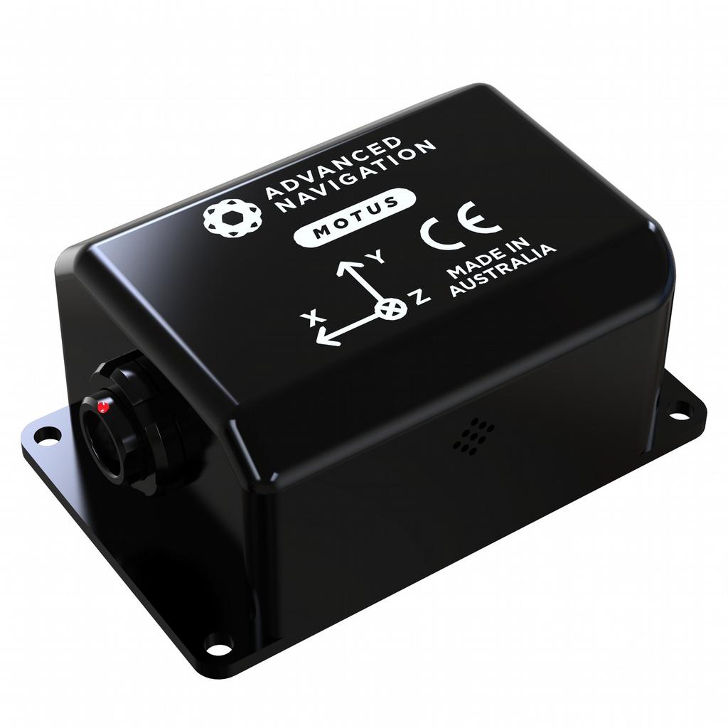
14 Page of Version. 7//6 5.5 The Sensor Co-ordinate Frame Inertial sensors have different axes: X, Y and Z and these determine the directions around which angles and accelerations are measured. It is very important to align the axes correctly in installation otherwise the system won't work correctly. These axes are marked on the top of the device as shown in Illustration below with the X axis pointing in the direction of the connector, the Z axis pointing down through the base of the unit and the Y axis pointing out of the starboard side. Illustration : Motus axes Illustration : First right hand rule When installed in an application the X axis should be aligned such that it points forwards and the Z axis aligned so that it points down when level. A good way to remember the sensor axes is the right hand rule, which is visualised in Illustration. You take your right hand and extend your thumb, index and middle. Your thumb then denotes the X axis, your index denotes the Y axis and your middle denotes the Z axis. 5.6 Roll, Pitch and Heading Orientation can be described by the three angles roll, pitch and heading, these are known as the Euler angles. The rotation axes of roll, pitch and heading are shown visually in Illustration. The arrow indicates the positive rotation direction. Roll is the angle around the X axis and is zero when the unit is level. Pitch is the angle around the Y axis and is zero when the unit is level. Heading is the angle around the Z axis and is zero when the positive X axis is pointing to true north Second Right Hand Rule The two right hand rules are often the best way to memorise the sensor axes and directions of positive rotation. The first right hand rule gives the positive axis directions and is described in section 5.5. The second right hand rule shown in Illustration provides the direction of positive rotation. To use it, point your thumb in the positive direction of that axis, then the direction that your fingers curl over is the

15 Page of Version. 7//6 positive rotation on that axis. Illustration : Second right hand rule 5.6. Rotation Order When multiple axes are rotated, to imagine the final orientation the three rotations must be performed in the order heading first, then pitch and then roll. To deduce the final orientation the unit should first be considered level with the X axis pointing north and the Z axis pointing down. Heading is applied first, then pitch is applied and finally roll is applied to give the final orientation. This can be hard for some people to grasp at first and is often best learned experimentally by rotating Motus with your hand whilst watching the orientation plot in real time on the computer. 5.7 Geodetic Co-ordinate System The geodetic co-ordinate system is the most popular way of describing an absolute position on the Earth. It is made up of the angles latitude and longitude combined with a height relative to the ellipsoid. Latitude is the angle that specifies the north to south position of a point on the Earth's surface. Longitude is the angle that specifies the east to west position of a point on the Earth's surface. The line of zero latitude is the equator and the line of zero longitude is the prime meridian. Illustration shows how latitude and longitude angles are used to describe a position on the surface of the Earth.

16 Page 5 of Version. 7//6 Illustration : Latitude and longitude represented visually to describe a position Illustration 5 shows latitude and longitude on a map of the world.
17 Page 6 of Version. 7//6 Equator Illustration 5: World map showing latitudes and longitudes Latitude and longitude give the D point on the surface of the Earth. These are combined with height to give the D position on the Earth. Height is the height above the WGS reference ellipsoid. The WGS reference ellipsoid is a model used to approximate sea level across the Earth. Therefore the height should be considered approximately relative to sea level. Due to the approximate nature of the WGS model, the WGS height will not be the same as the actual sea level. For example, in Australia, the WGS height at sea level is 9 metres at some points. 5. NED Co-ordinate Frame The NED (North East Down) co-ordinate frame is used to express velocities and relative positions. The origin of the co-ordinate frame can be considered the current position. From that origin, the north axis points true north and parallel to the line of longitude at that point. The east axis points perpendicular to the north axis and parallel to the line of latitude at that point. The down axis points directly down towards the centre of the Earth. See Illustration 6 for a graphical representation of the NED coordinate frame at a position on the Earth.
 co-ordinate frame is a Cartesian co-ordinate frame used to represent absolute positions on the Earth.")
18 Page 7 of Version. 7//6 Illustration 6: Graphic showing geodetic, NED and ECEF co-ordinates 5.9 ECEF Co-ordinate Frame The ECEF (Earth-centred earth-fixed) co-ordinate frame is a Cartesian co-ordinate frame used to represent absolute positions on the Earth. It's origin is at the centre of the Earth. ECEF is an alternative to the geodetic co-ordinate frame. It is represented by the three axes X, Y and Z which are presented graphically in Illustration 6. ECEF positions can be retrieved from Advanced Navigation products however the geodetic system is used as the default.

19 Page of Version. 7//6 6 Rugged Evaluation Kit Motus is supplied in an evaluation kit that contains everything required to get started operating the system right away. The evaluation kit is supplied in a plastic carry case to protect the equipment during shipping. Illustration 7: Motus Evaluation Kit case 6. Illustration : Motus Evaluation Kit contents Kit Contents. Motus. metre USB to RS cable 6. Quick Start. Plug the interface cable into Motus.. Plug the USB end of the interface cable into your computer.. Download the Motus Manager software from the Motus page of the Advanced Navigation website. Java is required to run the software. Java is available from if not already installed.. Click the connect button in Motus Manager. 5. The various windows in Motus Manager can be used to view the real time data. 6. To view the data logs, click disconnect in Motus Manager. In the tools menu, select log converter and press convert. The *.anpp binary log file will be converted to CSV files that can be opened with popular data processing programs such as Matlab or Microsoft Excel. The log files can be found in the same folder as the Motus Manager software.


20 Page 9 of Version. 7//6 7 OEM Evaluation Kit Motus OEM is supplied in an evaluation kit that contains everything required to get started operating the system right away. The evaluation kit is supplied in a plastic carry case to protect the equipment during shipping. Illustration 9: Motus OEM Evaluation Kit case 7. Illustration : Motus OEM Evaluation Kit contents Kit Contents. Motus OEM. Motus OEM development board. Mini USB cable 7. Quick Start. Mount the Motus OEM onto the Motus OEM development board and screw it down.. Plug one end of the USB cable into the Motus development board and the other end into your computer.. Download the Motus Manager software from the Motus page of the Advanced Navigation website. Java is required to run the software. Java is available from if not already installed.. Click the connect button in Motus Manager. 5. The various windows in Motus Manager can be used to view the real time data. 6. To view the data logs, click disconnect in Motus Manager. In the tools menu, select log converter and press convert. The *.anpp binary log file will be converted to CSV files that can be opened with popular data processing programs such as Matlab or Microsoft Excel. The log files can be found in the
21 Page of Version. 7//6 same folder as the Motus Manager software.
22 Page of Version. 7//6. Part Numbers and Ordering Options Evaluation Kit Part Number Notes MOTUS-RUG-EK Motus Rugged Evaluation Kit Motus rugged evaluation kit Includes items listed in section 6. IMU functionality only AHRS and INS upgrade licenses can be purchased seperately, see section. MOTUS-OEM-EK Motus OEM Evaluation Kit Motus OEM evaluation kit Includes items listed in section 7. IMU functionality only AHRS and INS upgrade licenses can be purchased seperately, see section. Table : Evaluation kit part numbers. Standalone Unit Part Number Notes MOTUS-RUG Motus Rugged Unit Motus rugged unit No cables included IMU functionality only AHRS and INS upgrade licenses can be purchased seperately, see section. MOTUS-OEM Motus OEM Unit Motus OEM unit No cables included IMU functionality only AHRS and INS upgrade licenses can be purchased seperately, see section. Table 5: Standalone unit part numbers. Software License Upgrades These license upgrades can either be ordered with the unit or purchased later and installed in the field using Motus Manager.
23 Page of Version. 7//6 Part Number Notes MOTUS-LIC-AHRS AHRS license upgrade for Motus Software license upgrade that activates AHRS functionality of Motus unit. MOTUS-LIC-INS INS license upgrade for Motus Software license upgrade that activates INS functionality of Motus unit. Table 6: Software license upgrade part numbers. Accessories Part Number Notes A5-SDC796 ODU plug to FTDI Motus rugged ODU plug with metres of USB cable cable to FTDI USB plug, see section X.X A5-SDC7-M ODU plug with m cable (unterminated) Motus rugged ODU plug with metres of unterminated cable, see section X.X A5-SDC75 ODU to D9 connectors and DC socket Motus rugged ODU plug with metres of cable to industry standard D9 connectors and DC socket, see section X.X Table 7: Accessories part numbers
24 Page of Version. 7// Specifications Mechanical Drawings Illustration : Motus rugged mechanical drawings
25 Page of Version. 7//6 Illustration : Motus OEM mechanical drawings
26 Page 5 of Version. 7//6 9. Navigation Specifications Parameter Value Horizontal Position Accuracy. m Vertical Position Accuracy.5 m Horizontal Position Accuracy (RTK). m Vertical Position Accuracy (RTK).5 m Velocity Accuracy.7 m/s Roll & Pitch Accuracy.5 Roll & Pitch Accuracy (GNSS aided). Heading Accuracy (GNSS aided). Heading Accuracy (dual antenna GNSS).5 Orientation Range Unlimited Hot Start Time s Internal Filter Rate Hz Output Data Rate Up to Hz Table : Navigation specifications 9. Sensor Specifications Parameter Accelerometers Gyroscopes Magnetometers 5g 75 /s G ug. /hr - < mg < /hr - Initial Scaling Error <. % <. % <.7 % Scale Factor Stability <. % <. % <.9 % Non-linearity <.5 % <. % <. % Cross-axis Alignment Error <.5 <. <.5 Noise Density (Random Walk) ug/ Hz (.5 m/s/ hr) 7 /hr/ Hz (.7 / hr) ug/ Hz 9 Hz Hz Hz Range Bias Instability Initial Bias Bandwidth Table 9: Sensor specifications
27 Page 6 of Version. 7//6 9. Rugged Communication Specifications Parameter Value Interface RS (RS optional) Speed to M baud Protocol AN Packet Protocol Peripheral Interface x GPIO x Auxiliary RS GPIO Level 5 V or RS Table : Rugged communication specifications 9.5 OEM Communication Specifications Parameter Interface Value.V TTL serial port (5V tolerant input) Speed to M baud Protocol AN Packet Protocol Peripheral Interface GPIO Level x GPIO x Auxiliary serial port (.V TTL).V TTL (5V tolerant input) Table : OEM communication specifications 9.6 Rugged Hardware Specifications Parameter Operating Voltage Input Protection Power Consumption Value 5 to 6 V - to V.95 Watts (typical) Hot Start Battery Capacity > hrs Hot Start Battery Charge Time mins Hot Start Battery Endurance > years Operating Temperature - C to 5 C Environmental Sealing IP6 MIL-STD-G Shock Limit g Dimensions x 55 x mm Weight Table : Rugged hardware specifications 7 grams
28 Page 7 of Version. 7//6 9.7 OEM Hardware Specifications Parameter Operating Voltage Input Protection Power Consumption Value.5 to 5.5 V None.95 Watts (typical) Hot Start Battery Capacity > hrs Hot Start Battery Charge Time mins Hot Start Battery Endurance > years Operating Temperature - C to 5 C Environmental Sealing None Shock Limit g Dimensions x x mm Weight Table : OEM hardware specifications 6 grams
29 Page of Version. 7//6 9. Rugged Electrical Specifications Parameter Minimum Typical Maximum Power Supply Input Supply Voltage.5 V 6 V Input Protection Range - V V RS Tx Voltage Low -5.7 V Tx Voltage High 5V -5 V 6. V Tx Short Circuit Current ±7 ma Rx Threshold Low. V Rx Threshold High. V.7 V.5 V GPIO Output Voltage Low V. V Output Voltage High. V 5V Output Current 5 ma Input Voltage - V V Input Threshold Low.5 V Input Threshold High.5 V Table : Rugged electrical specifications 9.9 OEM Electrical Specifications Parameter Minimum Typical Maximum Power Supply Input Supply Voltage.5 V 5.5 V Input Protection Range None None Serial and GPIO Signal Levels Output Voltage Low V. V Output Voltage High. V. V Output Current Input Voltage ma V Input Threshold Low Input Threshold High Table 5: OEM electrical specifications 5.5 V. V V
30 Page 9 of Version. 7//6 9. Power Consumption Current Consumption (ma) Maximum Typical Voltage (V) Illustration : Maximum and typical current consumption across operating voltage 9. Rugged Connector Pin-out Power supply and signal connections are made through a ODU Mini-Snap Series B 9 pin connector. The ODU part number is SBSP9MCC-5. The connector provides a reliable and rugged connection to Motus under demanding conditions and is rated to IP6 in the mated condition. Plugs are supplied with metres of unterminated shielded cable with an outer protective jacket. Each individual wire is colour coded PFA coated AWG wire with an external shield and insulation. Custom cable lengths can be ordered by request.
31 Page of Version. 7//6 Illustration : ODU B series mating plug for Motus Pin Colour Function Black Ground Brown Power Supply White GPIO Green GPIO 5 Red Primary RS Transmit 6 Orange Primary RS Receive 7 Yellow Auxiliary RS Transmit Blue Auxiliary RS Receive 9 Pink Ground Table 6: Pin allocation table 9. Rugged Evaluation Kit USB Cable The evaluation kit is supplied with a metre cable with a Motus ODU plug on one end and an overmoulded RS to USB converter on the other end, please see Illustration 5. The cable is the same 9 wire cable supplied with unterminated ODU cables and all 9 wires are connected on the ODU end. If required, it is possible to cut off the overmoulded RS converter to get access to all the individual wires. The chip used in the overmoulded RS converter is an FTDI FTR and supports baud rates of up to,, baud.
32 Page of Version. 7//6 Illustration 5: Evaluation kit USB cable Pin Colour Function RS Converter Connection Black Ground USB Ground Brown Power USB 5 volt supply White GPIO Green GPIO 5 Red Primary RS Tx FTDI RS Rx 6 Orange Primary RS Rx FTDI RS Tx 7 Yellow Auxiliary RS Tx Blue Auxiliary RS Rx 9 Pink Ground Table 7: Evaluation kit USB cable pin-out 9. Rugged Optional Breakout Cable Advanced Navigation offers a pre-terminated breakout cable for access to all of Motus's pins. All external signal and power connections are provided with m of cable. The interface cable is provided with industry standard 9 pin DSUB connectors for each of the two RS communication channels and GPIO pins. The breakout cable is an optional extra and is not supplied as standard with the evaluation kit.
33 Page of Version. 7//6 Illustration 6: Optional breakout cable diagram Pin Colour Function Primary Auxiliary GPIO Black Ground Brown Power White GPIO Green GPIO 5 Red Primary RS Tx 6 Orange Primary RS Rx 7 Yellow Auxiliary RS Tx Blue Auxiliary RS Rx 9 Pink Ground Power Tip Ring Table : Optional breakout cable connector pin-out 9. Serial Number The serial number can be inspected by using the device information dialogue in the Motus Manager software, see section.7.. The primary serial number label is located inside the enclosure and is accessible only by Advanced Navigation technicians. The secondary serial number label is located on the outside rear of the enclosure with the serial number encoded in a D data matrix bar code to assist customers in tracking their units, see Illustration 7. The external label also contains the hardware version and build date. Applications are available for most smart-phones that can scan the D data matrix bar code to display the serial number.

34 Page of Version. 7//6 Illustration 7: Motus external serial number label
35 Page of Version. 7//6. Installation Installation Checklist. Securely mount the unit to the vehicle following the guidelines in section... Connect the connector cable to Motus and then connect the USB end to a computer.. Open the Motus Manager software and click connect.. If the unit is mounted in an alignment other than the standard alignment of X pointing forward and Z pointing down, this alignment offset will need to be entered into the Alignment Configuration dialogue in Motus Manager. Please see section.. for more details. 5. The system is now ready for use.. Position and Alignment When installing Motus into a vehicle, correct positioning and alignment are essential to achieve good performance. There are a number of goals in selecting a mounting site in your application, these are:. Motus should be mounted in an area that is not going to exceed it's temperature range.. Motus should be mounted away from vibration where possible.. Motus should be mounted close to the centre of gravity of the vehicle where possible.. If the magnetic sensors or magnetic heading are going to be used the Motus unit should be mounted away from sources of changing magnetic interference such as high current wiring, motors, moving steel masses and rotating or reciprocating machinery... Alignment The easiest way to align Motus is by installing it with the sensor axes aligned with the vehicle axes. This means that the X axis points forward towards the front of the vehicle and the Z axis points down towards the ground. If aligning Motus with the vehicle axes is not possible or not optimal, it may be mounted in a different alignment and the alignment offset should be configured using the alignment configuration dialogue in Motus Manager, see section... For easy alignment, the set zero orientation button in the Motus Manager alignment dialogue can be used to set the current orientation as the zero orientation alignment, see section... Please note that this will only correct for roll and pitch offsets. Any heading offset will need to be entered manually and saved before using this function.
36 Page 5 of Version. 7//6. Mounting Plate Motus's mounting plate and hole guide is shown below in Illustration. The holes are designed for M bolts. The alignment holes can be used to ensure precise alignment of Motus through the use of alignment pins. Illustration : Motus mounting plate. Power Supply A high level of power supply filtering has been built into Motus to allow for reliable operation in demanding environments. Motus contains a fully isolated power supply and has separate grounds for power and signal to ensure that power supply noise does not corrupt communications or cause ground loops with other equipment. When wiring the system, the signal ground should be routed with the primary RS, auxiliary RS, GNSS RS and GPIO pins. The power ground should be routed with the power supply to the power source. A power supply should be selected that can provide at least the maximum current calculated from the graph in Error: Reference source not found. Motus contains an active protection circuit on the power supply input that protects the
37 Page 6 of Version. 7//6 unit from under-voltage, over-voltage and reverse polarity events. The protection circuit shuts off power and automatically recovers the unit to full operation once the fault is removed. Take care when running the unit close to its under-voltage lockout of 9 V because small voltage drops can engage the under-voltage shutdown and potentially oscillate between the on and off state. It is recommended that the unit is always run at V or more to avoid issues associated with this..5 Vibration Motus is able to tolerate a high level of vibration compared to other inertial systems. There is however a limit to the amount of vibration that Motus can tolerate and large levels of vibration will cause Motus's accuracy to degrade. When mounting Motus to a platform with vibration there are several options. It is recommended to first try mounting Motus and see whether it can tolerate the vibrations. The raw sensor view in the Motus Manager software can give you a good idea of how bad the vibrations are. If the vibrations are causing the sensors to go over range you will need to take preventative steps against the vibration. If Motus is unable to tolerate the vibrations there are several options:. Try to find a mounting point with less vibration.. Motus can be mounted on top of a small flat piece of rubber. Please note that this may cause small changing orientation errors due to flexing of the rubber.. Motus can be mounted to a plate which is then mounted to the platform through vibration isolation mounts.

38 Page 7 of Version. 7//6. INS and AHRS Operation Initialisation There are four different levels of initialisation on Motus. These are orientation, navigation, heading and time. The initialisation can be monitored by inspecting the status view in Motus Manager, see section.7.. Illustration 9: The four initialisation levels After all four levels of initialisation, Motus's filter takes several minutes to achieve it's full accuracy. It is recommended to wait two minutes after initialisation for applications requiring high accuracy... Orientation Initialisation Orientation initialisation occurs automatically upon power on and typically completes within several seconds. Once orientation initialisation is complete, the roll, pitch and angular velocity values will be valid. When Motus starts up, it assumes that it can be in any orientation. To determine it's orientation it uses the accelerometers to detect the gravity vector. Whilst this is occurring, if there are random accelerations present, these can cause an incorrect orientation to be detected. To prevent this, Motus monitors the accelerometers and gyroscopes and restarts the orientation detection if there are sudden movements. It is however still possible under some circumstances for it to miss minor movements and start with a small orientation error. In this scenario Motus will progressively correct the orientation error over a period of several seconds... Navigation Initialisation Please note that when operating Motus with the AHRS license navigation will not initialise. Navigation initialisation completes once the system has determined a starting position. The most common method of navigation initialisation is for the system to get a D GNSS fix from a connected GNSS receiver. If the system is hot starting it will remember it's position from when it was switched off and use this as the starting position. The other possibility for navigation initialisation is an external position
39 Page of Version. 7//6 source, see section 5. for more information. In a situation where a GNSS fix is not available to initialise navigation, it can be initialised manually by entering a position into the position dialogue in Motus Manager, see section... Once navigation initialisation is complete, the position, velocity and acceleration values will be valid... Heading Initialisation Heading initialisation completes once the system has determined a heading. The conditions required to determine a heading depend upon the heading source being used, see section.. If magnetic heading is enabled as a heading source the heading initialisation should complete within seconds after power on. If magnetic heading is disabled and velocity heading is used as the only heading source, the heading will initialise once the system travels at a speed of over.5 metres/second for over 5 seconds with a D GNSS fix or other source of velocity information. If the system is hot starting it will remember it's heading from when it was switched off and use this as the starting heading until another source becomes available. Until the heading has been initialised, the system will not be able to navigate without a GNSS fix or other position source and the roll and pitch values will not be able to reach full accuracy... Time Initialisation Time initialisation completes once the system has determined time accurately. For this to occur the system must receive rough time as well as a PPS signal on one of the GPIO pins. The rough time is typically received from a GNSS receiver when it achieves a fix. It is also possible to provide an external source of time, see section 5. for more information on external time sources. Until the time has initialised the values of unix time and formatted time that Motus outputs will not be valid and may change.. Hot Start Motus is the first GNSS/INS on the market with hot start functionality. This allows Motus to start inertial navigation within seconds. Motus's hot start is always on and fully automatic. A next generation backup battery system within Motus provides the hot start ability for more than hours without power. When Motus hot starts it assumes that it is in the same state it was when it lost power and begins navigating from that position. When the GNSS achieves it's first fix, if this position deviates from the hot start position, Motus will jump to the new position without causing any side effects to the filter. Whilst Motus is without power it keeps track of the time accurately to within second so that the time is immediately valid on a hot start. Motus's hot start is of particular benefit to vehicle tracking and robotics applications. The primary benefits are immunity and fast recovery from power failure as well as fast startup time.
40 Page 9 of Version. 7//6. Time Motus was designed to provide a highly accurate time reference. When a GNSS fix is available Motus's time is accurate to within 5 nanoseconds. When a GNSS fix is lost, Motus's time accuracy typically remains within microseconds over extended time periods. When Motus hot starts the time accuracy is typically within second immediately on startup and corrected to within 5 nanoseconds as soon as a GNSS fix is achieved and PPS received. To synchronise with Motus's high accuracy time, both the packet protocol and a PPS line must be used.. Heading Source There are three different heading sources available for Motus. By default Motus uses both magnetic heading and velocity heading. It is possible to use multiple heading sources and this will often provide performance benefits... Magnetic Heading This is the default heading source and works well in the majority of cases. When using magnetic heading, calibration is required every time Motus's installation changes. The downside of magnetic heading is that prolonged dynamic magnetic interference sources can cause heading errors... Velocity Heading Velocity heading works by deriving heading from the direction of velocity and acceleration. Velocity heading works well with cars, boats, fixed wing aircraft and other vehicles that don't move sideways. Velocity heading does not work with helicopters and other D vehicles. The downside of velocity heading is that heading can not be measured until the vehicle moves at a horizontal speed of over.5 metres/second with a GNSS fix. The benefits of velocity heading are that it is immune to magnetic interference and no calibration is required when Motus's installation changes... External Heading External heading can be used if there is some other way to derive heading that is external to Motus. Examples include dual antenna GNSS systems, gyrocompasses, reference markers and SLAM systems. The heading must be fed into Motus using the External Heading Packet or through NMEA into a GPIO pin..5 Magnetics Static magnetic interference is defined as anything that provides a fixed vector of magnetic interference to Motus, an example would be the steel body of a car that Motus is mounted on. Dynamic magnetic interference is defined as anything that provides varying magnetic interference, an example would be when Motus is mounted on an engine and the pistons within are moving relative to Motus and providing a changing magnetic field. Static magnetic interference is resolved through magnetic calibration and dynamic magnetic interference is compensated by a filter algorithm but should be minimised
41 Page of Version. 7//6 where possible through installation location. To compensate for static magnetic interference, magnetic calibration should be performed any time Motus's installation changes. Motus contains a dynamic magnetic compensation filter that is able to mitigate the effects of short term magnetic interference sources while in operation. For example if Motus is installed in a car and the car drives over a large piece of magnetised steel, this will be compensated for. Another example is driving through a tunnel which is built from heavily reinforced concrete. It is important to note that for Motus's dynamic magnetic compensation filter to operate correctly, Motus needs to get a GNSS fix at least once every time it is moved more than 5km. Each time Motus moves more than 5km the new position is stored permanently and allows Motus to update it's world magnetic model values. There are three types of magnetic calibration available, these are D calibration, D calibration and automatic calibration. D calibration involves one level rotation about the Z axis and is designed for vehicles that cannot easily or safely be turned upside down, such as full size cars, planes and boats. D calibration involves rotating through all orientations and is designed for vehicles that can easily and safely be rotated upside down, such as model size vehicles. D calibration offers slightly better performance and is recommended where possible. Automatic magnetic calibration continuously and automatically calibrates for static magnetic interference while the unit is in operation. It is not as accurate as the D or D calibration, however it is very convenient for applications where Motus needs to just work without user intervention. Please note that if Motus is going to be used in a vehicle, the calibration should be performed while Motus is mounted in and fixed to that vehicle. This means that the whole vehicle must be moved to perform the calibration. The calibration needs to be performed in an area away from sources of magnetic interference. For example if Motus is installed in a car, the calibration should not involve driving over steel drains or reinforced concrete etc. If Motus is being calibrated to operate standalone, the calibration should not be done on a desk with a steel frame..5. D Magnetic Calibration The following procedure should be used to perform a D magnetic calibration..5.. Using the Motus Manager Software. The unit should be powered on while the vehicle is in a level orientation and kept stationary.. After power on wait 5 minutes for the temperature and filter to stabilise.. Open Motus Manager and connect to the device. Ensure that the device has either a GNSS fix or the position has been manually entered before proceeding.. In the Tools menu, open Magnetic Calibration. Click the D Calibration button. See section Whilst keeping as level as possible, rotate the vehicle in either direction through one and a quarter full rotations. In a car this can be achieved by driving in one and a quarter circles.
42 Page of Version. 7//6 6. Check the status in the Magnetic Calibration window to ensure that the calibration completed successfully. If not successful click Cancel, wait minutes and repeat from step. Do not press the save button in the lower half of the dialogue, this will over write the new calibration values. The calibration values are automatically saved internally..5.. Using the Packet Protocol. The unit should be powered on while the vehicle is in a level orientation and kept stationary.. After power on wait 5 minutes for the temperature and filter to stabilise.. Ensure that the device has a GNSS fix before proceeding. Send the Magnetic Calibration Configuration Packet with the action Start D Magnetic Calibration. 5. Whilst keeping as level as possible, rotate the vehicle in either direction through one and a quarter full rotations. In a car this can be achieved by driving in one and a quarter circles. 6. Read the Magnetic Calibration Status Packet to ensure that the calibration completed successfully. If not successful, send the Magnetic Calibration Configuration Packet with the action Cancel, wait minutes and repeat from step..5. D Magnetic Calibration The following procedure should be used to perform a D magnetic calibration..5.. Using the Motus Manager Software. The unit should be powered on and the vehicle kept stationary.. After power on wait 5 minutes for the temperature and filter to stabilise.. Open Motus Manager and connect to the device. Ensure that the device has a GNSS fix before proceeding.. In the Tools menu, open Magnetic Calibration. Click the D Calibration button. See section.9.. The following steps 5, 6 and 7 can be performed in any order. 5. Slowly rotate the vehicle twice around the X axis (roll). 6. Slowly rotate the vehicle twice around the Y axis (pitch). 7. Slowly rotate the vehicle twice around the Z axis (heading).. Check the status in the Magnetic Calibration window to ensure that the calibration completed successfully. If not successful click Cancel, wait minutes and repeat from step. Do not press the save button in the lower half of the dialogue, this will over write the new calibration values. The calibration values are automatically saved internally.
43 Page of Version. 7//6.5.. Using the Packet Protocol. The unit should be powered on and the vehicle kept stationary.. After power on wait 5 minutes for the temperature and filter to stabilise.. Ensure that the device has a GNSS fix before proceeding. Send the Magnetic Calibration Configuration Packet with the action Start D Magnetic Calibration. The following steps 5, 6 and 7 can be performed in any order. 5. Slowly rotate the vehicle twice around the X axis (roll). 6. Slowly rotate the vehicle twice around the Y axis (pitch). 7. Slowly rotate the vehicle twice around the Z axis (heading). Read the Magnetic Calibration Status Packet to ensure that the calibration completed successfully. If not successful, send the Magnetic Calibration Configuration Packet with the action Cancel, wait minutes and repeat from step..5. Automatic Magnetic Calibration Automatic magnetic calibration is an algorithm that continuously and automatically calibrates for static magnetic interference. Automatic magnetic calibration is enabled by default and it is recommended to keep it enabled for all vehicle types. When used on top of a D or D calibration it can give the best results from magnetic heading. Every time Motus is powered on in a cold start ( hours without power) the automatic calibration is reset. The automatic magnetic calibration starts operating when Motus is travelling at a speed over 5 m/s with a GNSS fix and velocity heading turned on. Automatic magnetic calibration is not as accurate as D or D calibration, however it is sufficient for most vehicles and allows Motus to be installed into vehicles and operated without user intervention. Automatic magnetic calibration can be turned off using the filter options dialogue in Motus Manager, see section Disabling Magnetometers In situations where there is very strong dynamic magnetic disturbances present, it is recommended to disable the magnetometers. When the magnetometers are disabled a secondary heading source is required otherwise may become inaccurate. Velocity heading is the recommended source. Please see section. for information on heading sources. The magnetometers can be disabled using the filter options dialogue in Motus Manager, see section....6 Data Anti Aliasing Internally Motus's filters update at Hz. When Motus outputs data, most applications require the data at a much lower rate (typically < Hz). This causes a problem for time based data such as velocities and accelerations where aliasing will occur at the lower rate. To prevent this problem, if the output rate is lower than Hz, Motus will low pass filter the values of the time dependent data between packets to prevent aliasing. This is only the case when a packet is set up to output at a certain
44 Page of Version. 7//6 rate. If the packet is simply requested no anti aliasing will occur. Additionally there is no anti aliasing for non time dependent fields such as position..7 Vehicle Profiles Motus supports a number of different vehicle profiles. These vehicle profiles impose constraints upon the filter that can increase performance. If your application matches one of the available vehicle profiles, it is recommended to select it for use in the filter options dialogue in Motus Manager, see section... For a list of the different vehicle profiles please see section Please note that if the wrong vehicle profile is selected it can cause a significant decrease in performance.. Odometer Pulse Length For Motus to use a wheel speed sensor or odometer input, it must know the pulse length of the signal. The pulse length is the distance in metres between low to high transitions of the signal. The odometer pulse length can either be entered manually or automatically calibrated by Motus. To enter the pulse length manually, please use the odometer configuration dialogue in Motus Manager, see section..7. To automatically calibrate the odometer pulse length please use the procedure listed below in section... By default the odometer will automatically calibrate itself... Odometer Automatic Pulse Length Calibration Procedure. Ensure that the signal is connected correctly and that the GPIO pin is configured as an odometer input using the GPIO configuration dialogue in Motus Manager, see section..6.. Open Motus Manager, connect to Motus and open the odometer configuration dialogue. In the odometer configuration dialogue tick the automatic pulse length calibration check box and press the write button, see section..7.. Wait until Motus has a continuous GNSS fix and then drive metres over flat terrain with as little turning as possible.. If Motus loses a GNSS fix for any extended period of time during the calibration, the distance travelled will be reset. The distance travelled can be checked in the odometer configuration dialogue to ensure that it has passed metres. 5. Once metres has been driven, press the read button and check that the automatic pulse length check box becomes un-ticked and the pulse length value is read..9 Reversing Detection Reversing detection is an algorithm that can detect when the vehicle is travelling in reverse. Knowledge of reverse motion is important when using velocity heading or odometer input to provide correct results. If Motus is fitted to a vehicle that does not reverse or doesn't use velocity heading or odometer, this function should be disabled. Reversing detection is enabled by default and it can be disabled using the filter configuration dialogue in Motus Manager, see section...
45 Page of Version. 7//6. Motion Analysis Motion analysis is an artificial intelligence algorithm that associates patterns in high frequency inertial data with the speed of the vehicle. After power on it takes some time to match patterns with speed before it will become active. Motion analysis only activates when dead reckoning and is most effective when the vehicle is near stationary. Motion analysis does not work in all situations and it's primary benefit is in ground vehicles. When active it can be recognised by Hz steps in velocity data. Motion analysis is disabled by default and can be enabled using the filter configuration window in Motus Manager, see section.... Heave Motus can provide vertical heave position at four different points on a ship. Motus's heave filter is always on and fully automatic. After power on, Motus requires approximately 5 minutes for it's heave filter to converge upon an accurate solution. Heave works without a GNSS fix, however best heave performance is achieved when Motus has a GNSS fix. By default Motus provides heave from the point at which the Motus unit is mounted, however it can provide heave at four different offset points on the ship. To set the heave offsets, either use the heave configuration dialogue in Motus Manager, see section..9.. Environmental Exposure Whilst Motus is environmentally protected, there are clearly defined limits to this protection that must be adhered to for reliable operation. Motus is only protected when it's connector is mated. When any of these connections are not made the unit offers no environmental protection. Spanners or tools should never be used to tighten the connectors. They should only ever be finger tight... Temperature Motus should not be subjected to temperature's outside of it's operating range. Subjecting Motus to temperature's outside of the storage range can cause failure of the system... Water Motus is water-proof to the IP6 standard which means that it can be submersed in water to a depth of up to metres only. Submersion to depths beyond metres can cause water entry and destruction of the internal electronics... Salt Motus is made from marine grade aluminium which gives it reasonably good salt water corrosion resistance. However Motus cannot tolerate extended periods of time in salt water environments. After any contact with salt water environments, Motus should be
46 Page 5 of Version. 7//6 thoroughly rinsed with fresh water... Dirt and Dust Motus is completely sealed against dirt and dust entry. It is important to note that this is only the case when the connectors are mated. When un-mating the connectors if the Motus unit is dirty or dusty, the dirt should be rinsed off with fresh water first and then dried off. This is to prevent dirt or dust entering the connectors which can cause them to fail...5 PH Level Environments with a high or low PH level can cause the Motus enclosure to corrode. If Motus comes into contact with these environments it should be rinsed in fresh water as soon as possible. It is not recommended to operate Motus in non neutral PH environments...6 Shocks Motus can tolerate shocks to 5g, however continuous shocks of this severity are likely to cause premature failure. Shocks above 5g can effect the factory sensor calibration and degrade performance. Normally shocks to Motus when mounted in a vehicle are fine. Even a high speed car crash is likely to reach a peak of only 5g. Shocks directly to Motus's enclosure can more easily go over the limit however so care should be taken when handling the unit prior to mounting.
47 Page 6 of Version. 7//6 Motus Manager Motus Manager is a software tool provided by Advanced Navigation for logging, testing, display and configuration of Motus. It is designed to be simple and easy to use. Illustration : Screenshot of Motus Manager
48 Page 7 of Version. 7//6. Software Changelog Version.. Date Changes //6 Initial Release System Requirements The software includes a D mapping display which requires a modern D graphics card and up to date drivers to run. If your machine does not meet the graphics requirements the mapping view will only show space without a globe. When Motus is running at very high output rates e.g. Hz, Motus Manager can consume significant system resources handling the large quantity of data.. Installation Motus Manager does not need to be installed and can be run from any directory by double clicking on it. Motus Manager requires a recent version of Java, available at On some systems to open the program it may be necessary to right click and select open with Java Runtime Environment. The Motus evaluation kit makes use of an FTDI USB to RS device. The drivers are normally installed automatically, if not they are available from Troubleshooting Please contact support@advancednavigation.com.au if you are having issues... All Platforms If the globe does not appear in the D map area, this indicates that either your graphics card is not powerful enough or your graphics card driver is out of date... Windows There is a well known problem with USB serial devices under Windows known as crazy mouse. The problem occurs when the system mistakenly installs the USB serial device as a mouse. Unfortunately Microsoft has not fixed this problem in over 5 years, so it probably won't be fixed. If you experience this problem, often a restart will resolve it. Otherwise there is a tool available at that can fix the issue. If the serial port does not show up when you plug in your Motus USB device, you may need to install the drivers from If you experience a blue screen of death whilst using Motus Manager, this is typically a problem associated with older FTDI drivers. To resolve the problem, install the latest drivers from When operating Motus at a very high data rate, data can be lost due to the latency of

49 Page of Version. 7//6 the FTDI driver. To resolve this problem the latency of the driver should be reduced by going to control panel system device manager ports and right click on the USB serial port, then click properties. In the properties window click the port settings tab and then the advanced button. You then need to change the latency timer setting to ms. Please see the screenshot in Illustration. Illustration : Screenshot of latency timer setting.. Linux If serial ports do not show up, the typical cause is permissions. The user should add themselves to the dialout group with the command sudo adduser username dialout. Compiz causes issues with the D mapping. If you are experiencing problems it is
50 Page 9 of Version. 7//6 recommended to turn off compiz. Modemmanager can also sometimes cause problems on Linux installations. If you are not using a modem, it is recommended to remove modemmanager with the command sudo apt-get remove modemmanager. Motus Manager is able to run on the OpenJDK JRE but it uses significantly more system resources than when it is running on the Oracle JRE.
51 Page 5 of Version. 7//6.5 Main View Illustration : Screenshot of Motus Manager main view.5. Serial Port The serial port dialogue is used to connect to Motus. You should select a serial port and baud rate and click connect. The default baud rate of Motus is 5. The connection indicator displays whether there is communication with a Motus unit..5. Attitude Indicator The aircraft style attitude indicator shows roll and pitch through a virtual horizon. Around the sides heading, speed and height are shown. All units are SI (metric) and degrees..5. Status Indicator The status indicator section contains a Motus status indicator, a fix indicator and a
52 Page 5 of Version. 7//6 satellites table..5.. Motus Status Indicator This indicator shows any problems with Motus. Before a GNSS fix is achieved it will show the status Filter not initialised. Once the filter has initialised it should show Healthy. Clicking on the indicator will show the detailed status flags..5.. Fix Indicator This shows the status of the GNSS fix. Under normal operating conditions it should show either D Fix or SBAS Fix. When satellite visibility is poor it may show either D Fix or No Fix..5.. Satellites Table The satellites table shows the number of active satellites being used in the current GNSS solution. More detailed information can be found in the satellites view..5. D Map The D map shows Motus's position on the Earth as well as a red trail of position history. When the filter initialises the map will automatically reset the view to Motus's location. To move the camera click and drag on the map. To zoom in and out use the scroll wheel. To change the camera view right click and drag or shift click and drag D Map Controls Reset View This resets the map view to Motus's current position Clear History This clears the current position history, this is the red trail shown on the map..6 Logging Motus Manager features a fully automatic logging system. Every time the serial port connect button is clicked Motus Manager starts a new log file in either the current directory or the user's home directory. The log file is given the file name MotusLog_date_time.anpp and contains all of the raw data received from Motus in the AN packet protocol. The log files are closed when the serial port is disconnected. To convert these log files into easily accessible formats, the log converter dialogue in the tools menu can be used, see section.9.. The log converter dialogue creates a folder and generates files in the CSV (comma separated values) format that can be easily opened with Microsoft Excel, Matlab, libreoffice and most other data analysis programs. It also creates a GPX file of position that is designed to be opened with Google Earth.


53 Page 5 of Version. 7//6 Illustration : Screenshot showing log file and log conversion folder.7 Views The views menu contains a number of different options for viewing data from Motus. Illustration : Screenshot of Motus Manager views menu.7. Device Information


54 Page 5 of Version. 7//6 Illustration 5: Screenshot of Motus Manager device information dialogue.7. Status Status shows Motus's complete status as contained in the system state packet detailed in section Illustration 6: Screenshot of Motus Manager status dialogue

55 Page 5 of Version. 7//6.7. Satellites Satellites shows detailed information on the satellites that Motus's GNSS receiver is tracking. Elevation and azimuth are in units of degrees. Illustration 7: Screenshot of Motus Manager satellites dialogue

56 Page 55 of Version. 7//6.7. Raw Sensors Raw sensors shows the temperature calibrated raw sensor values. Illustration : Screenshot of Motus Manager raw sensors dialogue

57 Page 56 of Version. 7//6.7.5 Orientation Orientation shows Motus's orientation, angular velocity and orientation error. Illustration 9: Screenshot of Motus Manager orientation dialogue

58 Page 57 of Version. 7//6.7.6 Position Position shows Motus's position and position error. Latitude and longitude are converted to North and East metres from a reference point that can be reset. Illustration : Screenshot of Motus Manager position dialogue

59 Page 5 of Version. 7//6.7.7 Velocity and Acceleration Velocity and Acceleration shows Motus's velocity, acceleration and g-force. Illustration : Screenshot of Motus Manager velocity and acceleration dialogue

60 Page 59 of Version. 7//6.7. D Model This dialogue shows a real-time D model of Motus's orientation. Illustration : Screenshot of Motus Manager D model dialogue


61 Page 6 of Version. 7//6.7.9 Communications Statistics This dialogue shows statistics on the data packets received from Motus and can be useful in diagnosing signal integrity problems. Illustration : Screenshot of Motus Manager communications statistics dialogue.7. Heave For the heave dialogue to function the heave packet (ID 5) must be set to output periodically using the Packet Rates dialogue. Illustration : Screenshot of Motus Manager heave dialogue


62 Page 6 of Version. 7//6. Configuration The configuration menu contains a number of dialogues for the configuration of Motus. Illustration 5: Screenshot of Motus Manager configuration menu.. Configuration Export The configuration export dialogue can be used to export all Motus settings to a file. This file can be imported at a later date or on other units. This is useful to restore a unit to preset configuration at a later date or for batch configuration of multiple units. Illustration 6: Screenshot of Motus Manager configuration export dialogue

63 Page 6 of Version. 7//6.. Filter Options For most applications the default filter options should be used and only the vehicle profile set. If in doubt please contact support@advancednavigation.com.au. Illustration 7: Screenshot of Motus Manager filter options dialogue
 and the Raw Sensors Packet (ID ) at Hz and these typically provide all the data that a user will require.")
64 Page 6 of Version. 7//6.. Packet Rates The packet rates dialogue allows the user to specify which packets output on a periodic basis and at what rate. The default packets enabled are the System State Packet (ID ) and the Raw Sensors Packet (ID ) at Hz and these typically provide all the data that a user will require. These two packets need to be enabled for the data graphs to update in Motus Manager. Other state packets can be enabled as required. Please see the Packet Summary table in section 6.7 for a list of all packets. Illustration : Screenshot of Motus Manager packet rates dialogue

65 Page 6 of Version. 7//6.. Alignment Configuration The alignment configuration dialogue is used to set the alignment offsets of the system installation. It is important to set the values in this dialogue correctly for accurate results. For most applications only the GNSS antenna offset values need to be entered and the rest of the values can be left at their factory defaults of zero. Illustration 9: Screenshot of Motus Manager alignment configuration dialogue... Alignment Offset If Motus is installed into the vehicle with the X axis pointing forwards and the Z axis pointing down, then no alignment offset is required and the roll, pitch and heading offset values can remain at the factory defaults of zero. If the unit is installed in a different orientation then the roll, pitch and heading offset must be entered. For example if the unit is installed on its side with the X axis pointing up and the Z axis pointing forwards and no change to the Y axis, then this would result in a pitch offset of +9 degrees with roll and heading remaining zero. If there is a small misalignment due to mechanical mounting error this can be compensated for by setting the vehicle stationary on a level surface and pressing the zero current orientation button. Please note that this will only correct for roll and pitch offsets, the heading offset must be entered manually and saved before using this function. All the other offsets will be measured in the realigned body co-ordinate frame (X positive forward, Z positive down) after being corrected for any alignment offset entered.
.")
66 Page 65 of Version. 7//6... GNSS Antenna Offset The GNSS antenna offset is measured from the centre of the Motus unit to the centre of the antenna in the body co-ordinate frame (X positive forward, Z positive down).... Odometer Offset The odometer offset is measured from the centre of the Motus unit to the point at which the vehicle's tyre makes contact with the road in the body co-ordinate frame (X positive forward, Z positive down).... External Data Offset These values are only required for speciality applications operating with external sources of data. Please contact support@advancednavigation.com.au for assistance with these values...5 Baud Rates When changing baud rates, some Microsoft Windows machines are unable to function at the higher baud rates. It is recommended to test the baud rate first with the permanent box unticked. This way, if it is not possible to communicate at the higher baud rate, a power cycle can be used to revert to the previous baud rate. Illustration : Screenshot of Motus Manager baud rates dialogue


67 Page 66 of Version. 7//6..6 GPIO Configuration This dialogue allows the user to select the function of the GPIO pins and Auxiliary RS. These functions change dynamically and are effective immediately upon pressing save. Please note that GPIO pins function at RS levels for data functions and to 5 volt levels for all other functions. The internal hardware automatically reconfigures based upon the selected function. Illustration : Screenshot of Motus Manager GPIO configuration dialogue..7 Odometer The odometer dialogue allows the user to configure the odometer pulse length and view the real time odometer data to verify correct operation. Illustration : Screenshot of Motus Manager odometer configuration dialogue


68 Page 67 of Version. 7//6.. Reset The reset button causes the system to perform a power cycle as if the unit had the power removed and reapplied. The factory restore button causes the system to erase all settings and restore factory defaults. It also erases the hot start data so that the system is forced to perform a cold start. Illustration : Screenshot of Motus Manager reset dialogue..9 Heave Offset The heave offset dialogue allows the user to move the heave measurement points to different positions on the vessel. When the values are zero the measurement point is the centre of the Motus unit. This can be offset to a different position on the ship by entering the offset value from the centre of the Motus unit to the desired position in the body co-ordinate frame (X positive forwards, Z positive down). Please note that these values only apply to the Heave Packet. NMEA, TSS and Simrad heave is not affected by the values in this dialogue which are always measured at the centre of the Motus unit. Illustration : Screenshot of Motus Manager heave offset dialogue

69 Page 6 of Version. 7//6.. GPIO Output The GPIO output configuration dialogue allows the user to configure the output rates for the GPIO and Auxiliary RS data functions NMEA, TSS and PASHR. Illustration 5: Screenshot of Motus Manager GPIO output configuration dialogue


70 Page 69 of Version. 7//6.. Manual Initialisation This dialogue can be used to manually initialise Motus when a GNSS fix is not available. Setting the position will initialise the navigation filter. Setting the heading will initialise the heading. Illustration 6: Screenshot of Spatial Manager manual initialisation dialogue.9 Tools The tools menu contains tools for performing procedures with Motus. Illustration 7: Screenshot of Motus Manager tools menu.9. Terminal The terminal is only used during specialised technical support with Advanced Navigation engineers.

71 Page 7 of Version. 7//6.9. Magnetic Calibration The magnetic calibration dialogue allows the user to perform magnetic calibration as well as view and modify the magnetic calibration values. The actual magnetic calibration is performed inside the Spatial unit. This dialogue does not have any smarts, it is just a control and display interface. Illustration : Screenshot of Spatial Manager magnetic calibration dialogue


72 Page 7 of Version. 7//6.9. Firmware Update The firmware update dialogue is used to update Motus's firmware. Advanced Navigation firmware files have the extension.anfw. The dialogue shows the version number of the firmware file along with the date and time it was generated by engineering. Illustration 9: Screenshot of Motus Manager firmware update dialogue.9. Log Converter This tool allows the user to convert Motus log files into various standard formats that are readable by many programs. The position offset values can used to project the exported position to a point other than the centre of the Motus unit. For most users these values should be left at zero. Illustration 5: Screenshot of Motus Manager log converter dialogue

73 Page 7 of Version. 7//6.9.5 Network Connect The network connect dialogue allows Spatial Manager to make a connection to Spatial over a TCP/IP network rather than the default serial port connection. This allows Spatial to be used with ethernet to serial converters. Advanced Navigation recommends Lantronix ethernet to serial converters. Illustration 5: Screenshot of Spatial Manager network connect dialogue
74 Page 7 of Version. 7//6. OEM Integration OEM PCB Mechanical Mounting Motus OEM mounts to its target PCB through the use of four mounting holes on the aluminium frame. The aluminium frame is designed to achieve effective mating height for the board to board connector without any additional components. Once the Motus OEM is connected to target PCB, four M.6 screws and washers and nuts on the back side of the target PCB are used to hold the Motus OEM in place, please see Illustration 5. The length of the M.6 screws will be depended on the thickness of the target PCB. M.6xmm screws are recommended for.6mm thickness target PCBs. Illustration 5: Motus OEM exploded mounting view

75 Page 7 of Version. 7//6 Illustration 5: Motus OEM development board Illustration 5: Motus OEM mounted on development board. OEM Electrical Connector The electrical connection to the Motus OEM PCB is through a Hirose DF series pin micro pitch board to board connector. These connectors have shock absorbing features, a large self-alignment distance and high contact reliability. A positive click should be felt when successful mating occurs between Motus OEM and the target board. It should be noted that this connector is not designed for the Motus OEM to be plugged in whilst power is applied to the user's PCB and connector mating cycles should not exceed 5 cycles to ensure connector reliability. The manufacturers part number for the required PCB connector is Hirose Part #: DFC(.)-DS-.V(5) The connector can be ordered from the following distributors using the following numbers: Digikey Part #: H95CT-ND Mouser Part #: 79-DFCDS.V5 Please see Illustration 55 below for the connector pin numbering.
76 Page 75 of Version. 7//6 Illustration 55: Motus OEM connector pin numbering
77 Page 76 of Version. 7//6 Pin Function Supply Voltage Ground Supply Voltage Ground 5 Supply Voltage 6 Ground 7.V translator supply, see section.. Ground 9 Primary UART receive Reset line, see section.. Primary UART transmit GPIO No connection GPIO 5 No connection 6 Auxiliary UART transmit 7 No connection Auxiliary UART receive 9 No connection No connection Table 9: Pin allocation table.. Interoperability with Different Voltage Systems All signals are. volt level, however inputs are tolerant to 5 volt signals from the target interface. If you require a different voltage level to be compatible with your target system it is recommended that you install a voltage level translator between the signals of each device. To power the translator.v is provided on pin 7 of the Motus OEM connector. This supply is only capable of driving up to 5mA and should be appropriately decoupled when powering a circuit... Reset Line The reset line is internally pulled high on Motus OEM. This pin must be left floating for normal operation. If a user wishes to reset Motus OEM the pin can be pulled low externally to force a reset. It is important that this signal is not driven high under any circumstances as it will prevent the Motus OEM from functioning correctly. Please keep the reset line track length to a minimum to avoid noise.
78 Page 77 of Version. 7//6.. Basic Connection Please see Illustration 56 for the basic electrical connections required by Motus OEM. Illustration 56: Motus OEM basic electrical connections. Recommended Footprint The footprint for Motus OEM incorporates four through-hole for M.6 screws to pass through and SMD pads for the board to board connector. The board to board connector should be the only component within the keep out area as shown in Illustration 57 and Illustration 5.

79 Page 7 of Version. 7//6 Illustration 57: Photo of Motus OEM mounting PCB footprint 5 A 6. 7 "Keep Out" Area.9 Illustration 5: Recommended footprint for Motus OEM..7. x.7.7 DETAIL A SC ALE : PCB footprint files are provided in the documentation section of the website. Please contact Advanced Navigation support if you have any issues or to verify your footprint is correct.
80 Page 79 of Version. 7//6. OEM Power Supply A high level of power supply filtering has been built into Motus OEM, however it is still recommended that the power supply be free of significant noise. The unit is only rated for inputs from.5 V to 5.5 V, exceeding 6 V can cause permanent damage to the unit. On start-up of the Motus OEM the device will initially draw an increased impulse current (~ma for microseconds) whilst it charges on board capacitors. It is important that the user's circuit is tolerant to these small impulses on start-up to avoid unsuccessful power up. It is recommended that a supply is selected that can provide a maximum current of.5a. Switch-mode supplies are suitable as Motus OEM has onboard filters to remove any supply noise and ripple..5 OEM Pin Protection Users should ensure that any signals that are connected externally from the PCB, including GPIO and UART pins, are adequately protected. The use of a 5V zener diode and k resistor should provide enough protection for the majority of use cases, see Illustration 59. External interface pins on Motus have on board pull-up/pull-down resistors enabled to avoid signals oscillating when not connected. The user shouldn't need to place any pull-up or pull-down resistors on their PCB. Illustration 59: Motus OEM external signal protection example

81 Page of Version. 7//6 OEM Development Board The OEM development board is a configurable PCB that provides developers with easy access to all of the features of the Motus OEM unit through a number of different interfaces. Illustration 6 shows an image of the OEM development board. Illustration 6: Motus OEM development board

82 Page of Version. 7//6. Serial UART to USB Converter An FTDI FTR USB to serial UART converter chip is included on board to allow the Motus OEM to interface directly to a computer through USB. Two status LEDs indicate the flow of data to and from the USB port. USB drivers for all operating systems can be downloaded directly from FTDI's website at All development boards are shipped with this interface enabled as standard.. Dual RS Transceiver An Exar Corporation SPEU dual channel serial UART to RS transceiver is included on the development board to allow developers to communicate with the Motus OEM unit via RS. The SPEU allows baud rates of up to baud. Channel of the SPEU is for use with the primary serial port on the Motus OEM unit and Channel of the SPEU is for use with GPIO (RS TX ) and GPIO (RS RX ). Connection to the RS level signals is through a x.5mm header, see Illustration 6. This header is on the left of the board and allows developers to attach wires or headers as needed. Please note that by default the SPEU is disabled. Switch turns it on, please see section.. Illustration 6: RS header with functions labelled. GPIO Header and Status LEDs Users have access to multi-purpose GPIO pins from Motus OEM. These are available

83 Page of Version. 7//6 on the 7x.5mm header, see Illustration 6. Two of these pins (GPIO & ) are also connected to LEDs on the development board. When using a GPIO in certain input functions, the LED can cause interference with the signal. In this situation, the LED's resistor should be removed. When using the GPIO lines for off board functions it is important to note that these signals are not protected against static charges, overvoltage or over-current events. Failure to protect the signals may result in damage to Motus OEM. Other pins on the GPIO header include a regulated.v supply from Motus that can supply up to 5mA, Motus' reset line and the external voltage input (VEXT). Illustration 6: GPIO header with functions labelled. Configuration Switches The OEM development board contains a DIP switch array that allows the user to route signals between the USB to serial converter, RS converter and GPIO header. The configuration switches are shown below in Illustration 6 in their default positions. The default position routes Motus' primary serial port to the USB to serial converter and has GPIO and GPIO connected only to the GPIO header. Please see Table for the configuration switch functions.
84 Page of Version. 7//6 Illustration 6: Configuration switches in their default position Switch Default Function Off Power on RS transceiver. When the RS transceiver is powered on GPIO and will be connected to RS TX and RS RX respectively. It will no longer be possible to use GPIO in a TTL level mode. The primary serial port TX will also be connected to RS TX but the primary serial port RX will only be connected to RS RX if switch is turned on. Off Connect primary serial port RX to RS transceiver (RS RX ). Please note that only one of the switches, or should be turned on at once to prevent short circuit. Off Connect primary serial port RX to USB serial converter. Please note that only one of the switches, or should be turned on at once to prevent short circuit. Off Connect primary serial port RX to GPIO header (UART RX). Please note that only one of the switches, or should be turned on at once to prevent short circuit. Table : Configuration switch functions.. Primary Serial Port to USB Illustration 6: Switch positions for primary serial port to USB (default)

85 Page of Version. 7//6.. Primary Serial Port to RS and GPIO & to RS Illustration 65: Switch positions for primary serial port to RS and GPIO & to RS.. Primary Serial Port and GPIO & to GPIO Header at TTL levels Illustration 66: Switch positions for primary serial port and GPIO & to GPIO header at TTL levels

86 Page 5 of Version. 7//6.5 Power source The development board has two power source options; USB power (5V nominal) or an external power source. By default, the development board is configured to use USB power. The external power source can be fed into the board through VEXT on either the GPIO header of RS header and can be any voltage between V and 6V. Please refer to the Motus OEM Reference Manual for full power supply requirements. The power source is selected by a three way switch, please see Illustration 67 and Illustration 6. Illustration 67: Power switch position for USB power (default).6 Illustration 6: Power switch position for external power Schematics See the following pages for the development board schematics.
Spatial Reference Manual
 Page of 9 Version. //7 Table of Contents 5 6 7 9 Revision History... Firmware Changelog... Hardware Changelog... 7 Introduction... Foundation Knowledge... 9 5. GNSS... 9 5. INS... 9 5. GNSS/INS... 9 5.
Orientus Reference Manual
 Page of 57 Version. 5// Table of Contents Revision History... Foundation Knowledge... 5. AHRS... 5. The Sensor Co-ordinate Frame... 5. Roll, Pitch and Heading... 5.. Roll... 6.. Pitch... 6.. Heading...
Spatial FOG Dual Reference Manual
 Spatial FOG Dual Reference Manual Page of Table of Contents 5 6 7 9 Revision History... Firmware Changelog... 9 Hardware Changelog... Introduction... Foundation Knowledge... 5. GNSS... 5. INS... 5. GNSS/INS...
Spatial FOG Reference Manual
 Spatial FOG Reference Manual Page of 7//6 Table of Contents 5 6 7 9 Revision History... Firmware Changelog... Hardware Changelog... Introduction... Foundation Knowledge... 5 5. GNSS... 5 5. INS... 5 5.
Spatial Dual Reference Manual
 Spatial Dual Reference Manual Page of Version.5 /9/7 Table of Contents 5 6 7 9 Revision History... Firmware Changelog... Hardware Changelog... Introduction... Foundation Knowledge... 5 5. GNSS... 5 5.
Inertial Sensors. Ellipse 2 Series MINIATURE HIGH PERFORMANCE. Navigation, Motion & Heave Sensing IMU AHRS MRU INS VG
 Ellipse 2 Series MINIATURE HIGH PERFORMANCE Inertial Sensors IMU AHRS MRU INS VG ITAR Free 0.1 RMS Navigation, Motion & Heave Sensing ELLIPSE SERIES sets up new standard for miniature and cost-effective
Inertial Sensors. Ellipse Series MINIATURE HIGH PERFORMANCE. Navigation, Motion & Heave Sensing IMU AHRS MRU INS VG
 Ellipse Series MINIATURE HIGH PERFORMANCE Inertial Sensors IMU AHRS MRU INS VG ITAR Free 0.1 RMS Navigation, Motion & Heave Sensing ELLIPSE SERIES sets up new standard for miniature and cost-effective
Inertial Sensors. Ellipse 2 Series MINIATURE HIGH PERFORMANCE. Navigation, Motion & Heave Sensing IMU AHRS MRU INS VG
 Ellipse 2 Series MINIATURE HIGH PERFORMANCE Inertial Sensors IMU AHRS MRU INS VG ITAR Free 0.1 RMS Navigation, Motion & Heave Sensing ELLIPSE SERIES sets up new standard for miniature and cost-effective
Inertial Sensors. Ellipse Series MINIATURE HIGH PERFORMANCE. Navigation, Motion & Heave Sensing IMU AHRS MRU INS VG
 Ellipse Series MINIATURE HIGH PERFORMANCE Inertial Sensors IMU AHRS MRU INS VG ITAR Free 0.2 RMS Navigation, Motion & Heave Sensing ELLIPSE SERIES sets up new standard for miniature and cost-effective
GPS-Aided INS Datasheet Rev. 3.0
 1 GPS-Aided INS The Inertial Labs Single and Dual Antenna GPS-Aided Inertial Navigation System INS is new generation of fully-integrated, combined GPS, GLONASS, GALILEO, QZSS, BEIDOU and L-Band navigation
GPS-Aided INS Datasheet Rev. 2.7
 1 The Inertial Labs Single and Dual Antenna GPS-Aided Inertial Navigation System INS is new generation of fully-integrated, combined GPS, GLONASS, GALILEO, QZSS and BEIDOU navigation and highperformance
GPS-Aided INS Datasheet Rev. 2.3
 GPS-Aided INS 1 The Inertial Labs Single and Dual Antenna GPS-Aided Inertial Navigation System INS is new generation of fully-integrated, combined L1 & L2 GPS, GLONASS, GALILEO and BEIDOU navigation and
GPS-Aided INS Datasheet Rev. 2.6
 GPS-Aided INS 1 GPS-Aided INS The Inertial Labs Single and Dual Antenna GPS-Aided Inertial Navigation System INS is new generation of fully-integrated, combined GPS, GLONASS, GALILEO and BEIDOU navigation
3DM-GX4-45 LORD DATASHEET. GPS-Aided Inertial Navigation System (GPS/INS) Product Highlights. Features and Benefits. Applications
 Product Highlights. Features and Benefits. Applications") LORD DATASHEET 3DM-GX4-45 GPS-Aided Inertial Navigation System (GPS/INS) Product Highlights High performance integd GPS receiver and MEMS sensor technology provide direct and computed PVA outputs in a
LORD DATASHEET 3DM-GX4-45 GPS-Aided Inertial Navigation System (GPS/INS) Product Highlights High performance integd GPS receiver and MEMS sensor technology provide direct and computed PVA outputs in a
xoem500 Hardware Integration Manual Inertial and GNSS measurement system Confidently. Accurately.
 xoem500 xf Inertial and GNSS measurement system Hardware Integration Manual Confidently. Accurately. Table of contents Introduction 5 Related documents 6 Precautions 7 Compliance testing 7 Hardware description
Inertial Navigation System
 Apogee Series ULTIMATE ACCURACY MEMS Inertial Navigation System INS MRU AHRS ITAR Free 0.005 RMS Motion Sensing & Georeferencing APOGEE SERIES makes high accuracy affordable for all surveying companies.
Inertial Systems. Ekinox Series TACTICAL GRADE MEMS. Motion Sensing & Navigation IMU AHRS MRU INS VG
 Ekinox Series TACTICAL GRADE MEMS Inertial Systems IMU AHRS MRU INS VG ITAR Free 0.05 RMS Motion Sensing & Navigation AEROSPACE GROUND MARINE EKINOX SERIES R&D specialists usually compromise between high
Inertial Navigation System
 Apogee Marine Series ULTIMATE ACCURACY MEMS Inertial Navigation System INS MRU AHRS ITAR Free 0.005 RMS Navigation, Motion & Heave Sensing APOGEE SERIES makes high accuracy affordable for all surveying
Attitude and Heading Reference Systems
 Attitude and Heading Reference Systems FY-AHRS-2000B Installation Instructions V1.0 Guilin FeiYu Electronic Technology Co., Ltd Addr: Rm. B305,Innovation Building, Information Industry Park,ChaoYang Road,Qi
1 General Information... 2
 Release Note Topic : u-blox M8 Flash Firmware 3.01 UDR 1.00 UBX-16009439 Author : ahaz, yste, amil Date : 01 June 2016 We reserve all rights in this document and in the information contained therein. Reproduction,
3DM -CV5-10 LORD DATASHEET. Inertial Measurement Unit (IMU) Product Highlights. Features and Benefits. Applications. Best in Class Performance
 Product Highlights. Features and Benefits. Applications. Best in Class Performance") LORD DATASHEET 3DM -CV5-10 Inertial Measurement Unit (IMU) Product Highlights Triaxial accelerometer, gyroscope, and sensors achieve the optimal combination of measurement qualities Smallest, lightest,
LORD DATASHEET 3DM -CV5-10 Inertial Measurement Unit (IMU) Product Highlights Triaxial accelerometer, gyroscope, and sensors achieve the optimal combination of measurement qualities Smallest, lightest,
BW-IMU200 Serials. Low-cost Inertial Measurement Unit. Technical Manual
 Serials Low-cost Inertial Measurement Unit Technical Manual Introduction As a low-cost inertial measurement sensor, the BW-IMU200 measures the attitude parameters of the motion carrier (roll angle, pitch
FLCS V2.1. AHRS, Autopilot, Gyro Stabilized Gimbals Control, Ground Control Station
 AHRS, Autopilot, Gyro Stabilized Gimbals Control, Ground Control Station The platform provides a high performance basis for electromechanical system control. Originally designed for autonomous aerial vehicle
SPEEDBOX Technical Datasheet
 SPEEDBOX Technical Datasheet Race Technology Limited, 2008 Version 1.1 1. Introduction... 3 1.1. Product Overview... 3 1.2. Applications... 3 1.3. Standard Features... 3 2. Port / Connector details...
3DM-GX3-45 Theory of Operation
 Theory of Operation 8500-0016 Revision 001 3DM-GX3-45 Theory of Operation www.microstrain.com Little Sensors, Big Ideas 2012 by MicroStrain, Inc. 459 Hurricane Lane Williston, VT 05495 United States of
OS3D-FG MINIATURE ATTITUDE & HEADING REFERENCE SYSTEM MINIATURE 3D ORIENTATION SENSOR OS3D-P. Datasheet Rev OS3D-FG Datasheet rev. 2.
 OS3D-FG OS3D-FG MINIATURE ATTITUDE & HEADING REFERENCE SYSTEM MINIATURE 3D ORIENTATION SENSOR OS3D-P Datasheet Rev. 2.0 1 The Inertial Labs OS3D-FG is a multi-purpose miniature 3D orientation sensor Attitude
High Performance Advanced MEMS Industrial & Tactical Grade Inertial Measurement Units
 High Performance Advanced MEMS Industrial & Tactical Grade Inertial Measurement Units ITAR-free Small size, low weight, low cost 1 deg/hr Gyro Bias in-run stability Datasheet Rev.2.0 5 μg Accelerometers
SERIES VECTORNAV TACTICAL SERIES VN-110 IMU/AHRS VN-210 GNSS/INS VN-310 DUAL GNSS/INS
 TACTICAL VECTORNAV SERIES TACTICAL SERIES VN110 IMU/AHRS VN210 GNSS/INS VN310 DUAL GNSS/INS VectorNav introduces the Tactical Series, a nextgeneration, MEMS inertial navigation platform that features highperformance
CODEVINTEC. Miniature and accurate IMU, AHRS, INS/GNSS Attitude and Heading Reference Systems
 45 27 39.384 N 9 07 30.145 E Miniature and accurate IMU, AHRS, INS/GNSS Attitude and Heading Reference Systems Aerospace Land/Automotive Marine Subsea Miniature inertial sensors 0.1 Ellipse Series New
ASC IMU 7.X.Y. Inertial Measurement Unit (IMU) Description.
 Description.") Inertial Measurement Unit (IMU) 6-axis MEMS mini-imu Acceleration & Angular Rotation analog output 12-pin connector with detachable cable Aluminium housing Made in Germany Features Acceleration rate: ±2g
Inertial Measurement Unit (IMU) 6-axis MEMS mini-imu Acceleration & Angular Rotation analog output 12-pin connector with detachable cable Aluminium housing Made in Germany Features Acceleration rate: ±2g
TACTICAL SERIES VECTORNAV INDUSTRIAL SERIES. Key Benefits Miniaturized surface mount & Rugged packaging. < 30 grams. Embedded Navigation Solutions
 TACTICAL SERIES VECTORNAV INDUSTRIAL SERIES VN100 IMU/AH AHRS VN200 GPS/INS VN300 DUAL GNSS/INS Key Benefits Miniaturized surface mount & Rugged packaging < 30 grams Embedded Navigation Solutions THE INDUSTRIAL
SERIES VECTORNAV INDUSTRIAL SERIES VN-100 IMU/AHRS VN-200 GPS/INS VN-300 DUAL GNSS/INS
 TACTICAL VECTORNAV SERIES INDUSTRIAL SERIES VN100 IMU/AHRS VN200 GPS/INS VN300 DUAL GNSS/INS VectorNav presents the Industrial Series, a complete line of MEMSbased, industrialgrade inertial navigation
Motion Reference Units
 Motion Reference Units MRU IP-67 sealed 5% / 5 cm Heave accuracy 0.03 m/sec Velocity accuracy 0.05 deg Pitch and Roll accuracy 0.005 m/sec 2 Acceleration accuracy 0.0002 deg/sec Angular rate accuracy NMEA
Motion Reference Units
 Motion Reference Units MRU Datasheet Rev. 1.3 IP-67 sealed 5% / 5 cm Heave accuracy 0.03 m/sec Velocity accuracy 0.05 deg Pitch and Roll accuracy 0.005 m/sec2 Acceleration accuracy 0.0002 deg/sec Angular
Motion & Navigation Solution
 Navsight Land & Air Solution Motion & Navigation Solution FOR SURVEYING APPLICATIONS Motion, Navigation, and Geo-referencing NAVSIGHT LAND/AIR SOLUTION is a full high performance inertial navigation solution
Installation Guide. Suitable for: OEM Integration OEM Installation Retro Fit Installation
 Installation Guide Suitable for: OEM Integration OEM Installation Retro Fit Installation DTI AngleBlaster release 1.1 DTI 2010 Overview Angleblaster Installation Guide A-1 To obtain the best accuracy from
INERTIAL LABS SUBMINIATURE 3D ORIENTATION SENSOR OS3DM
 Datasheet Rev..5 INERTIAL LABS SUBMINIATURE D ORIENTATION SENSOR TM Inertial Labs, Inc Address: 9959 Catoctin Ridge Street, Paeonian Springs, VA 2029 U.S.A. Tel: + (70) 880-4222, Fax: + (70) 95-877 Website:
ENHANCEMENTS IN UAV FLIGHT CONTROL AND SENSOR ORIENTATION
 Heinz Jürgen Przybilla Manfred Bäumker, Alexander Zurhorst ENHANCEMENTS IN UAV FLIGHT CONTROL AND SENSOR ORIENTATION Content Introduction Precise Positioning GNSS sensors and software Inertial and augmentation
1. ASSEMBLING THE PCB 2. FLASH THE ZIP LEDs 3. BUILDING THE WHEELS
 V1.0 :MOVE The Kitronik :MOVE mini for the BBC micro:bit provides an introduction to robotics. The :MOVE mini is a 2 wheeled robot, suitable for both remote control and autonomous operation. A range of
If you want to use an inertial measurement system...
 If you want to use an inertial measurement system...... which technical data you should analyse and compare before making your decision by Dr.-Ing. E. v. Hinueber, imar Navigation GmbH Keywords: inertial
IMU60 Inertial Measurement Unit
 Precision 6 DoF MEMS Inertial Measurement Unit Range: acc ±2g, gyro ±300 /s, (ODM supported) Acc Bias Instability: ±70mg, Gyro Bias Instability: 24 /h Data Update Rate: 100Hz Wide Input Power Range: 5~18VDC
EB-54X. EB-54X Datasheet
 GPS Engine Board EB-54X Datasheet EB-54X EB-54X is a complete GPS sub-system with 32 x 32 mm 2 In size. Equipped with antenna, back up battery GPS engine and onboard memory, it provides superior navigation
Long Range Wireless OSD 5.8G FPV Transmitter
 Long Range Wireless OSD 5.8G FPV Transmitter Built-in 10 Axis AHRS + MAVLINK + 600mW Support all flight controller and GPS 1 / 14 User's Guide Catalogue Product Instruction 3 Features 3 Specifications.4
Kongsberg Seatex AS Pirsenteret N-7462 Trondheim Norway POSITION 303 VELOCITY 900 HEADING 910 ATTITUDE 413 HEAVE 888
 WinFrog Device Group: Device Name/Model: Device Manufacturer: Device Data String(s) Output to WinFrog: WinFrog Data String(s) Output to Device: WinFrog Data Item(s) and their RAW record: GPS SEAPATH Kongsberg
GNSS Compass Reference Manual
 GNSS Compass Reference Manual Page of Version. // Table of Contents 6 7 9 Revision History... Firmware Changelog... 6 Hardware Changelog... 7 Introduction... Quick Start Guide... 9. NMEA Connection....
Revisions Revision Date By Changes A 11 Feb 2013 MHA Initial release , Xsens Technologies B.V. All rights reserved. Information in this docum
 MTi 10-series and MTi 100-series Document MT0503P, Revision 0 (DRAFT), 11 Feb 2013 Xsens Technologies B.V. Pantheon 6a P.O. Box 559 7500 AN Enschede The Netherlands phone +31 (0)88 973 67 00 fax +31 (0)88
GPS-G5 User s Manual
 GPS-G5 User s Manual Contents Using the GPS... 1 Description...1 Electrical Connections...2 Mounting...3 GPS Configuration...3 GPS Operation...3 Logging Device Configuration...4 Data Analysis...5 Specifications...
Cost efficient design Operates in full sunlight Low power consumption Wide field of view Small footprint Simple serial connectivity Long Range
 Cost efficient design Operates in full sunlight Low power consumption Wide field of view Small footprint Simple serial connectivity Long Range sweep v1.0 CAUTION This device contains a component which
TX CONTROLLER Model EM-IP Quick Start Guide
 TX CONTROLLER Model EM-IP Quick Start Guide 860 boul. de la Chaudière, suite 200 Québec (Qc), Canada, G1X 4B7 Tel.: +1 (418) 877-4249 Fax: +1 (418) 877-4054 E-Mail: gdd@gdd.ca Web site: www.gdd.ca Visit
DragonLink Advanced Transmitter
 DragonLink Advanced Transmitter A quick introduction - to a new a world of possibilities October 29, 2015 Written by Dennis Frie Contents 1 Disclaimer and notes for early release 3 2 Introduction 4 3 The
----STAR S86 GPS Receiver. User Guide. SOUTH CO., Ltd.
 ----STAR S86 GPS Receiver User Guide SOUTH CO., Ltd. www.southsurveying.com Sales@SOUTHsurveying.com 2 CONTENTS Chapter 1 Introduction... 1 STAR S86 GPS - System Summary... 1 Technical Specification...
BW-VG525 Serials. High Precision CAN bus Dynamic Inclination Sensor. Technical Manual
 Serials High Precision CAN bus Dynamic Inclination Sensor Technical Manual Introduction The Dynamic Inclination Sensor is a high precision inertial measurement device that measures the attitude parameters
Inertial Navigation System INS
 Inertial Navigation System INS DEMO PROGRAM INS DEMO User s Manual Revision 2.4 Revision history Revision Date Author Description 1.0 Jul.15, 2015 AK Released version. 1.2 Sep.03, 2015 ON 1. Implemented
A3 Pro INSTRUCTION MANUAL. Oct 25, 2017 Revision IMPORTANT NOTES
 A3 Pro INSTRUCTION MANUAL Oct 25, 2017 Revision IMPORTANT NOTES 1. Radio controlled (R/C) models are not toys! The propellers rotate at high speed and pose potential risk. They may cause severe injury
SP-6 magnetometer. User manual. Installation and in-flight calibration
 SP-6 magnetometer User manual Installation and in-flight calibration Note: This manual is applicable for SP-6 systems that contain in-flight calibration firmware released by MGL Avionics around the 15
Embedded Navigation Solutions VN-300 User Manual
 Embedded Navigation Solutions VN-300 User Manual Firmware v0.5.0.0 Document Revision 2.23 UM005 1 Document Information Title VN-300 User Manual Subtitle Inertial Navigation Modules Document Type User Manual
CAST Application User Guide
 CAST Application User Guide for DX900+ Electromagnetic Multilog Sensor U.S. Patent No. 7,369,458. UK 2 414 077. Patents Pending 17-630-01-rev.b 05/24/17 1 Copyright 2017 Airmar Technology Corp. All rights
MN5020HS Smart GPS Antenna Module
 1 Description The Micro Modular Technologies MN5020HS Smart Global Positioning System (GPS) Antenna Module is a complete 20-channel receiver with an integrated 18 x 18 mm patch antenna. With this highly
SL800 GNSS RTK System User Manual
 SL800 GNSS RTK System User Manual User Manual Revision SatLab SL800 GNSS Receiver Revision Date Revision Number Description 1 st Nov 2017 1 SL800 User Manual (Release V1.0) 1 Table of Contents Introduction...
1. Introduction. Quick Start Guide for GPS150 V1.02 TEL
 1. Introduction Congratulations on the purchase of your GPS150 Smart GPS/GLONASS Sensor. It is recommended that your receiver is installed by a professional installer. You will need to purchase a suitable
Cost efficient design Operates in full sunlight Low power consumption Wide field of view Small footprint Simple serial connectivity Long Range
 Cost efficient design Operates in full sunlight Low power consumption Wide field of view Small footprint Simple serial connectivity Long Range sweep v1.0 CAUTION This device contains a component which
Datasheet. Tag Piccolino for RTLS-TDoA. A tiny Tag powered by coin battery V1.1
 Tag Piccolino for RTLS-TDoA A tiny Tag powered by coin battery Features Real-Time Location with UWB and TDoA Technique Movement Detection / Sensor Data Identification, unique MAC address Decawave UWB Radio,
IG-2500 OPERATIONS GROUND CONTROL Updated Wednesday, October 02, 2002
 IG-2500 OPERATIONS GROUND CONTROL Updated Wednesday, October 02, 2002 CONVENTIONS USED IN THIS GUIDE These safety alert symbols are used to alert about hazards or hazardous situations that can result in
AIT2000 CLASS B AIS TRANSPONDER
 IMPORTANT NOTE The USB cable of the AIT2000 is designed to be used for configuring/programming the unit during installation and not for permanent connection to the boat s Navigation PC. If you intend to
SPAN Technology System Characteristics and Performance
 SPAN Technology System Characteristics and Performance NovAtel Inc. ABSTRACT The addition of inertial technology to a GPS system provides multiple benefits, including the availability of attitude output
BR2 Lap Beacon Manual
 MoTeC BR2 Lap Beacon Manual Contents Introduction... 1 Overview... 3 Operation...3 Orientation...5 Range...5 Alignment...5 Verifying Operation...6 Split Beacon Use...6 Configuration - Quick Start... 7
ARDUINO BASED CALIBRATION OF AN INERTIAL SENSOR IN VIEW OF A GNSS/IMU INTEGRATION
 Journal of Young Scientist, Volume IV, 2016 ISSN 2344-1283; ISSN CD-ROM 2344-1291; ISSN Online 2344-1305; ISSN-L 2344 1283 ARDUINO BASED CALIBRATION OF AN INERTIAL SENSOR IN VIEW OF A GNSS/IMU INTEGRATION
Underwater GPS User Manual
 Underwater GPS Document number W-DN-17002-3 Project Classification - Rev Prepared by Checked by Approved by Short description 1 2017-08-03 T. Trøite O. Skisland T. Trøite Initial 2 2017-08-04 T. Trøite
Brushed DC Motor Control. Module with CAN (MDL-BDC24)
") Stellaris Brushed DC Motor Control Module with CAN (MDL-BDC24) Ordering Information Product No. MDL-BDC24 RDK-BDC24 Description Stellaris Brushed DC Motor Control Module with CAN (MDL-BDC24) for Single-Unit
Stellaris Brushed DC Motor Control Module with CAN (MDL-BDC24) Ordering Information Product No. MDL-BDC24 RDK-BDC24 Description Stellaris Brushed DC Motor Control Module with CAN (MDL-BDC24) for Single-Unit
BRB900 GPS Telemetry System August 2013 Version 0.06
 BRB900 GPS Telemetry System August 2013 Version 0.06 As of January 2013, a new model of the BRB900 has been introduced. The key differences are listed below. 1. U-blox GPS Chipset: The Trimble Lassen IQ
NovAtel SPAN and Waypoint. GNSS + INS Technology
 NovAtel SPAN and Waypoint GNSS + INS Technology SPAN Technology SPAN provides continual 3D positioning, velocity and attitude determination anywhere satellite reception may be compromised. SPAN uses NovAtel
Lab 1 Navigation using a 2-axis accelerometer
 Measurement Technology and Uncertainty Analysis E7021E Torbjörn Löfquist EISLAB Luleå University of Technology (Revised: July 22, 2009, by Johan Carlson) Lab 1 Navigation using a 2-axis accelerometer Goal:
NovAtel s. Performance Analysis October Abstract. SPAN on OEM6. SPAN on OEM6. Enhancements
 NovAtel s SPAN on OEM6 Performance Analysis October 2012 Abstract SPAN, NovAtel s GNSS/INS solution, is now available on the OEM6 receiver platform. In addition to rapid GNSS signal reacquisition performance,
Inertial Systems. Ekinox 2 Series TACTICAL GRADE MEMS. Motion Sensing & Navigation IMU AHRS MRU INS VG
 Ekinox 2 Series TACTICAL GRADE MEMS Inertial Systems IMU AHRS MRU INS VG ITAR Free 0.02 RMS Motion Sensing & Navigation AEROSPACE GROUND MARINE EKINOX 2 SERIES R&D specialists usually compromise between
Jaguar Motor Controller (Stellaris Brushed DC Motor Control Module with CAN)
") Jaguar Motor Controller (Stellaris Brushed DC Motor Control Module with CAN) 217-3367 Ordering Information Product Number Description 217-3367 Stellaris Brushed DC Motor Control Module with CAN (217-3367)
Jaguar Motor Controller (Stellaris Brushed DC Motor Control Module with CAN) 217-3367 Ordering Information Product Number Description 217-3367 Stellaris Brushed DC Motor Control Module with CAN (217-3367)
ExpoM - ELF User Manual
 ExpoM - ELF User Manual Version 1.4 ExpoM - ELF User Manual Contents 1 Description... 4 2 Case and Interfaces... 4 2.1 Overview... 4 2.2 Multi-color LED... 5 3 Using ExpoM - ELF... 6 3.1 Starting a Measurement...
H3-IMU High Performance Inertial Measurement Unit
 FUNCTIONAL DESCRIPTION The H3 IMU provides serial digital outputs of triaxial acceleration, rate of turn (gyro) and magnetic field data. Custom algorithms provide high performance, temperature compensated
DEVICE CONFIGURATION INSTRUCTIONS
 WinFrog Device Group: Device Name/Model: Device Manufacturer: Device Data String(s) Output to WinFrog: WinFrog Data String(s) Output to Device: WinFrog Data Item(s) and their RAW record: GPS POS/MV (NMEA)
Installation & Quick Start Guide AIT2000 Class B AIS Transponder
 Installation & Quick Start Guide AIT2000 Class B AIS Transponder QUICK START AIT2000 - VR1.01 1. Introduction Congratulations on the purchase of your AIT2000 Class B AIS Transponder. It is recommended
10-35V (10 mt. cable)
") UX0GPGxx 10-35V (10 mt. cable) Issue A220302 1. INTRODUCTION This GPS receiver module is based on a ultimate 12 channel GPS engine. The GPS engine, interface electronics, and a passive GPS antenna are
UX0GPGxx 10-35V (10 mt. cable) Issue A220302 1. INTRODUCTION This GPS receiver module is based on a ultimate 12 channel GPS engine. The GPS engine, interface electronics, and a passive GPS antenna are
Motion Reference Unit MRU-P, MRU-PD
 Motion Reference Unit MRU-P, DEMO PROGRAM DEMO User s Manual Revision 1.1 Revision history Revision Date Author Description 1.0 Oct.10, 2016 AK Released version. 1.1 Nov.10,2016 AK Since MRU PD Demo Program
Vinyl Cutter Instruction Manual
 Vinyl Cutter Instruction Manual 1 Product Inventory Inventory Here is a list of items you will receive with your vinyl cutter: Product components (Fig.1-4): 1x Cutter head unit complete with motor, plastic
NEW TOUGHEST WIND SENSORS THE WORLD S 1:2
 F T 74 2 D ATA S H E E T NEW S U R FA C E M O U N T D E S I G N E D F O R I N T E G R AT I O N THE WORLD S TOUGHEST WIND SENSORS WWW.FTTECHNOLOGIES.COM 1:2 PROVEN IT LOOKS DIFFERENT BECAUSE IT IS DIFFERENT
Tarocco Closed Loop Motor Controller
 Contents Safety Information... 3 Overview... 4 Features... 4 SoC for Closed Loop Control... 4 Gate Driver... 5 MOSFETs in H Bridge Configuration... 5 Device Characteristics... 6 Installation... 7 Motor
GPS Position Sensor PS-2175
 In s tr u c ti o n M a n u a l 012-09919A GPS Position Sensor PS-2175! Table of Contents Contents Introduction........................................................... 3 Theory of Operation....................................................
era, eric, era-lora, eric-lora & eric-sigfox Evaluation Board with GNSS
 This board can be used for the evaluation and range testing of the following LPRS RF Modules: era400, era900, eric4, eric9, era-lora, eric-lora and eric-sigfox. The board is provided with a u-blox GNSS
al T TD ) ime D Faamily Products The RTD Family of products offers a full suite of highprecision GPS sensor positioning and navigation solutions for:
 ime D Faamily Products The RTD Family of products offers a full suite of highprecision GPS sensor positioning and navigation solutions for:") Reeal ynnamics al T amics (R TD ) ime D RTD) Time Dy Faamily mily ooff P roducts Products The RTD Family of products offers a full suite of highprecision GPS sensor positioning and navigation solutions
Reeal ynnamics al T amics (R TD ) ime D RTD) Time Dy Faamily mily ooff P roducts Products The RTD Family of products offers a full suite of highprecision GPS sensor positioning and navigation solutions
Configuring the Global Navigation Satellite System
 Configuring the Global Navigation Satellite System uses a satellite receiver, also called the global navigation satellite system (GNSS), as a new timing interface. In typical telecom networks, synchronization
LD2342 USWM V1.6. LD2342 V1.4 Page 1 of 18
 LD2342 USWM V1.6 LD2342 V1.4 Page 1 of 18 GENERAL WARNINGS All Class A and Class B marine Automatic Identification System (AIS) units utilize a satellite based system such as the Global Positioning Satellite
Inertial Systems. Ekinox 2 Series TACTICAL GRADE MEMS. Motion Sensing & Navigation IMU AHRS MRU INS VG
 Ekinox 2 Series TACTICAL GRADE MEMS Inertial Systems IMU AHRS MRU INS VG ITAR Free 0.02 RMS Motion Sensing & Navigation AEROSPACE GROUND MARINE EKINOX 2 SERIES R&D specialists usually compromise between
LORD USER MANUAL. 3DM-GQ4-45 Tactical Grade GNSS-Aided Inertial Navigation System (GNSS/INS)
") LORD USER MANUAL 3DM-GQ4-45 Tactical Grade GNSS-Aided Inertial Navigation System (GNSS/INS) MicroStrain Sensing Systems 459 Hurricane Lane Suite 102 Williston, VT 05495 United States of America Phone:
LORD USER MANUAL 3DM-GQ4-45 Tactical Grade GNSS-Aided Inertial Navigation System (GNSS/INS) MicroStrain Sensing Systems 459 Hurricane Lane Suite 102 Williston, VT 05495 United States of America Phone:
Installation & Quick Start Guide CLB2000 Class B AIS Transponder
 Installation & Quick Start Guide CLB2000 Class B AIS Transponder QUICK START CLB2000 - VR1.01 1. Introduction Congratulations on the purchase of your CLB2000 Class B AIS Transponder. It is recommended
CONDOR C1216 GPS RECEIVER MODULE technical notes ZELIA INTEGRATES ANTENNA, GPS RECEIVER, RTC AND LNA
 CONDOR C1216 GPS RECEIVER MODULE technical notes Zelia GPS RECEIVER MODULE TECHNICAL HIGHLIGHTS Integrated antenna element, GPS receiver, real-time clock, and low noise amplifier Receiver: Trimble Condor
The Signature VM package delivers vessel-mounted AD2CP capabilities based on present-day technology
 The package delivers vessel-mounted AD2CP capabilities based on present-day technology Until now, ADCP current surveys have been complex and time-consuming processes. A successful current survey depends
Configuring the Global Navigation Satellite System
 Configuring the Global Navigation Satellite System Effective Cisco IOS-XE Release 3.17, the Cisco ASR-920-12SZ-IM router uses a satellite receiver, also called the global navigation satellite system (GNSS),
Receiver Technology CRESCENT OEM WHITE PAPER AMY DEWIS JENNIFER COLPITTS
 CRESCENT OEM WHITE PAPER AMY DEWIS JENNIFER COLPITTS With offices in Kansas City, Hiawatha, Calgary and Scottsdale, Hemisphere GPS is a global leader in designing and manufacturing innovative, costeffective,
Featherweight GPS Tracker User s Manual June 16, 2017
 Featherweight GPS Tracker User s Manual June 16, 2017 Hardware Configuration and Installation The dimensions for the board are provided below, in inches. Note that with the antenna installed, the total
How to introduce LORD Sensing s newest inertial sensors into your application
 LORD TECHNICAL NOTE Migrating from the 3DM-GX4 to the 3DM-GX5 How to introduce LORD Sensing s newest inertial sensors into your application Introduction The 3DM-GX5 is the latest generation of the very
SPAN Data Logging for Inertial Explorer
 APN-076 ev C SPAN Data Logging for Inertial Explorer Page 1 November 16, 2017 Overview This document provides an overview of the OEM6 and OEM7 SPAN logs used for post-processing in Inertial Explorer (IE)
Introduction. Overview. Outputs Normal model 4 Delta wing (Elevon) & Flying wing & V-tail 4. Rx states
 & Flying wing & V-tail 4. Rx states") Introduction Thank you for purchasing FrSky S6R/S8R (SxR instead in this manual) multi-function telemetry receiver. Equipped with build-in 3-axis gyroscope and accelerometer, SxR supports various functions.
Introduction Thank you for purchasing FrSky S6R/S8R (SxR instead in this manual) multi-function telemetry receiver. Equipped with build-in 3-axis gyroscope and accelerometer, SxR supports various functions.