Spatial Reference Manual
|
|
|
- Audra Oliver
- 6 years ago
- Views:
Transcription


1
2 Page of 9 Version. //7 Table of Contents Revision History... Firmware Changelog... Hardware Changelog... 7 Introduction... Foundation Knowledge GNSS INS GNSS/INS AHRS The Sensor Co-ordinate Frame Roll, Pitch and Heading Second Right Hand Rule Rotation Order Geodetic Co-ordinate System NED Co-ordinate Frame ECEF Co-ordinate Frame... Evaluation Kit Evaluation Kit Contents Quick Start Troubleshooting... 6 Part Numbers and Ordering Options Evaluation Kit Standalone Unit Accessories... Specifications Mechanical Drawings Navigation Specifications.... Sensor Specifications.... GNSS Specifications....5 Communication Specifications....6 Hardware Specifications....7 Electrical Specifications.... Power Consumption Connector Pin-out Evaluation Kit USB Cable Optional Breakout Cable...7. Sensor Calibration.... Serial Number... Installation Installation Checklist Position and Alignment Alignment Mounting Plate Power Supply GNSS Antenna Odometer Factory VSS Signal OBDII Odometer Interface...
3 Page of 9 Version. // Aftermarket Wheel Speed Sensor Radar Speed Sensor Magnetics Vibration... 5 Operation Initialisation Orientation Initialisation Navigation Initialisation Heading Initialisation..... Time Initialisation.... Hot Start.... Time Heading Source Magnetic Heading Velocity Heading External Heading Magnetics D Magnetic Calibration Using the Spatial Manager Software Using the Packet Protocol D Magnetic Calibration Using the Spatial Manager Software Using the Packet Protocol Automatic Magnetic Calibration Disabling Magnetometers Sensors Range Data Anti Aliasing Vehicle Profiles Odometer Pulse Length Odometer Automatic Pulse Length Calibration Procedure...5. Reversing Detection Motion Analysis Differential GNSS Raw Satellite Data Post Processing Vents RAIM Heave Environmental Exposure Temperature Water Salt Dirt and Dust PH Level Shocks Spatial Manager Software Changelog System Requirements Installation Troubleshooting... 6
4 Page of 9 Version. //7.. All Platforms Windows Linux Main View Serial Port Attitude Indicator Status Indicator Spatial Status Indicator Fix Indicator Satellites Table D Map D Map Controls Reset View Clear History Logging View Menu Device Information Status Satellites Raw Sensors Orientation Position Velocity and Acceleration D Model Communications Statistics Heave Configuration Configuration Export Sensor Ranges Filter Options Packet Rates Alignment Configuration Alignment Offset GNSS Antenna Offset Odometer Offset External Data Offset Baud Rates GPIO Configuration..... Odometer Reset..... Reference Position Offsets..... GPIO Output Configuration..... Manual Initialisation..... Gimbal....9 Tools Terminal Magnetic Calibration Firmware Update Log Converter NTRIP Client... 7
5 Page of 9 Version. //7.9.6 Network Connect... 7 Interfacing.... Communication..... Baud Rate.... External Data.... GPIO Pins and Auxiliary RS.... Dynamic Pin Functions PPS Output GNSS Fix Output Odometer Input Stationary Input Pitot Tube Input NMEA Input NMEA Output Novatel GNSS Input Topcon GNSS Input ANPP Input ANPP Output Disable Magnetometers Disable GNSS Disable Pressure Set Zero Orientation Alignment System State Packet Trigger Raw Sensors Packet Trigger RTCM Differential GNSS Corrections Input Trimble GNSS Input u-blox GNSS Input Hemisphere GNSS Input Left Wheel Speed Sensor Right Wheel Speed Sensor PPS Input Wheel Speed Sensor Wheel Encoder Phase A Wheel Encoder Phase B Event Input Event Input TSS Output Simrad Output Simrad Output Serial Port Passthrough Gimbal Encoder Phase A Gimbal Encoder Phase B Odometer Direction, Forward Low Odometer Direction, Forward High...96 Advanced Navigation Packet Protocol Data Types Packet Structure Header LRC Packet ID Packet Length... 9
6 Page 5 of 9 Version. //7.. CRC Packet Requests Packet Acknowledgement Packet Rates Packet Timing Packet Summary System Packets..... Acknowledge Packet Acknowledge Result..... Request Packet..... Boot Mode Packet Boot Mode Types..... Device Information Packet Restore Factory Settings Packet Reset Packet Verification Sequence Values Serial Port Pass-through Packet Pass-through Routes State Packets System State Packet System Status Filter Status GNSS Fix Status Unix Time Seconds Microseconds Unix Time Packet Formatted Time Packet Status Packet Position Standard Deviation Packet Velocity Standard Deviation Packet Euler Orientation Standard Deviation Packet Quaternion Orientation Standard Deviation Packet Raw Sensors Packet Raw GNSS Packet Raw GNSS Status Satellites Packet Detailed Satellites Packet Satellite Systems Satellite Frequencies Geodetic Position Packet ECEF Position Packet UTM Position Packet NED Velocity Packet Body Velocity Packet Acceleration Packet Body Acceleration Packet Euler Orientation Packet Quaternion Orientation Packet DCM Orientation Packet Angular Velocity Packet...
7 Page 6 of 9 Version. //7.9. Angular Acceleration Packet External Position & Velocity Packet External Position Packet External Velocity Packet External Body Velocity Packet External Heading Packet Running Time Packet Local Magnetic Field Packet Odometer State Packet External Time Packet External Depth Packet Geoid Height Packet RTCM Corrections Packet External Pitot Pressure Packet Wind Packet Heave Packet Raw Satellite Data Packet Satellite Frequencies Tracking Status External Odometer Packet Odometer flags External Air Data Packet External Air Data Flags Notes Gimbal State Packet Automotive Packet.... Configuration Packets..... Packet Timer Period Packet UTC Synchronisation Packet Timer Period..... Packets Period Packet Clear Existing Packets Packet Period..... Baud Rates Packet Sensor Ranges Packet Accelerometers Range Gyroscopes Range Magnetometers Range Installation Alignment Packet Alignment DCM Filter Options Packet Vehicle Types Advanced Filter Parameters Packet GPIO Configuration Packet GPIO Functions GPIO Functions Auxiliary RS Transmit Functions Auxiliary RS Receive Functions Magnetic Calibration Values Packet..... Magnetic Calibration Configuration Packet...
8 Page 7 of 9 Version. //7... Magnetic Calibration Actions..... Magnetic Calibration Status Packet Magnetic Calibration Status..... Odometer Configuration Packet Set Zero Orientation Alignment Packet Reference Point Offsets Packet GPIO Output Configuration Packet NMEA Fix Behaviour GPIO Output Rates GPIO Output Rates Index User Data Packet GPIO Input Configuration Packet...
9 Page of 9 Version. //7 Revision History Version Date Changes. //7 Updated firmware changelog, section Updated hardware changelog, section Added raw satellite data operation, section. Added post processing operation, section. Added raw satellite data packet, section.9.. //6 Updated firmware changelog, section Updated hardware changelog, section Updated images in foundation knowledge, section 5 Added antenna offset diagrams, section 9.5 Updated Spatial Manager changelog, section. Updated sensor specifications with more detail, section.. /5/5 Updated firmware changelog, section Updated hardware changelog, section Updated axes image, section 5.5 Added part numbers and ordering information, section 7 Updated optional breakout cable, section. Updated power consumption graph, section. Updated D magnetic calibration procedure, section.5. Updated automatic magnetic calibration, section.5. Added differential GNSS, section. Updated Spatial Manager changelog, section. Added gimbal encoder phase a function, section.. Added gimbal encoder phase b function, section..5 Added odometer direction, forward low, section..6 Added odometer direction, forward high, section..7 Updated reset packet, section..6 Updated UTM position packet, section.9.5 Added gimbal state packet, section.9. Added automotive packet, section.9. Heave offsets packet changed name to reference point offsets packet, format remains the same, section.. Added user data packet, section..6 Added GPIO input configuration packet, section..7 Fixed a document heading spacing issue. /9/ Added firmware changelog, section Added hardware changelog, section Updated GNSS specifications for version. hardware, section. Updated connector pin-out to include pink wire, section.9 Added evaluation kit USB cable, section. Added optional breakout cable, section. Added serial number information, section. Updated GNSS antenna, section 9.5 Updated OBDII Odometer, section 9.6.
10 Page 9 of 9 Version. //7 Version Date Changes Updated initialisation with more information, section. Updated hot start for clarity, section. Updated D magnetic calibration procedure for clarity, section.5.. Updated D magnetic calibration procedure for clarity, section.5.. Updated all screenshots in Spatial Manager, section Updated Spatial Manager changelog, section. Updated Spatial Manager Linux troubleshooting, section.. Added Spatial Manager D model, section.7. Added Spatial Manager communications statistics, section.7.9 Added Spatial Manager GPIO output configuration, section.. Added Spatial Manager position configuration, section.. Added serial port pass-through GPIO function, section.. Added packet timing, section.6 Added serial port pass-through packet, section..7 Changed raw GNSS packet, section.9. Changed wind estimation packet to wind packet and changed from read only to read/write, section.9. Added external odometer packet, section.9. Added external air data packet, section.9. Added stunt plane vehicle profile, section..6. Updated set zero orientation packet, section.. NMEA output configuration packet changed to GPIO output configuration packet, section..5 Total page numbering in header fixed. /9/ Manual updated for Spatial v. hardware Updated photo for Spatial v. hardware Added evaluation kit, section 6 Updated mechanical drawings, section. Updated navigation specifications, section. Updated sensor specifications, section. Updated communication specifications, section.5 Updated hardware specifications, section.6 Updated electrical specifications, section.7 Updated connector pin-out, section.9 Updated mounting plate, section 9. Updated odometer information, section 9.6 Added reversing detection, section. Added motion analysis, section. Updated D magnetic calibration procedure, section.5. Added automatic magnetic calibration, section.5.
11 Page of 9 Version. //7 Version Date Changes Integrated Spatial Manager manual, section Added Auxiliary RS information, section. Updated NMEA input, section..6 Updated NMEA output, section..7 Added wheel speed sensor function, section..5 Added wheel encoder phase A function, section..6 Added wheel encoder phase B function, section..7 Added event input, section.. Added event input, section..9 Added TSS output, section.. Added Simrad output, section.. Added Simrad output, section.. Updated filter status, section.9.. Added GNSS fix status, section.9.. Updated baud rates packet, section.. Updated filter options packet, section..6 Updated GPIO configuration packet, section.. Added NMEA output configuration packet, section // Added additional magnetic information, section.5 Added PPS input, section.. Updated detailed satellites packet, section.9. Corrected geoid height packet, section // Added Added Added Added Added Added.5 7// Added input voltage range to electrical specifications, section.7 Added left wheel speed sensor input, section.. Added right wheel speed sensor input, section.. Added external time packet, section.9. Added external depth packet, section.9. Added geoid height packet, section.9.5 Updated GPIO functions tables, section... 6// Yaw terminology changed to heading for increased clarity Reworded installation magnetics for increased clarity, section 9.7 Reworded initialisation for increased clarity, section. Reworded operation magnetics for increased clarity, section.5 Added vehicle profiles information, section. Updated NMEA output, section..7. 9// Installation magnetics changed, section 9.7 Heading source added, section. heave information, section.7 RTCM corrections packet, section.9.6 external pitot pressure packet, section.9.7 wind estimation packet, section.9. heave packet, section.9.9 heave configuration packet, section..
12 Page of 9 Version. //7 Version Date Changes Disabling magnetometers changed, section.5. GPIO information updated, section. Added NMEA input GPGLL support, section..6 Added NMEA input GPHDT support, section..6 Added NMEA input HEHDT support, section..6 Updated NMEA output, section..7 Added RTCM corrections input, section.. Added Trimble GNSS input, section..9 Added u-blox GNSS input, section.. Added Hemisphere GNSS input, section.. Updated GPIO functions tables, section... // Sensor specifications updated, section. Fixed error in odometer state packet, section.9.. // Added information on sensor calibration, section. Added odometer installation information, section 9.6 Added hot start information, section. Added time information, section. Added odometer pulse length information, section.9 Added RAIM information, section.6 Updated Odometer input, section.. Updated NMEA output, section..7 Added disable magnetometers GPIO function, section.. Added disable GNSS GPIO function, section.. Added disable pressure GPIO function, section.. Added set zero alignment GPIO function, section..5 Added system state packet trigger GPIO function, section..6 Added raw sensors packet trigger GPIO function, section..7 Updated acknowledge packet, section.. Added running time packet, section.9. Added local magnetic field packet, section.9. Added odometer state packet, section.9. Updated installation alignment packet, section..5 Fixed error in filter options packet, section..6 Updated GPIO configuration packet, section.. Added odometer configuration packet, section.. Added set zero orientation alignment packet, section... 6/9/ PPS description updated, section.. Corrected reset packet, section..6 Corrected external body velocity packet, section.9. Revised alignment packet, section..5 Grammar and spelling corrections.6 // Grammar corrections throughout
13 Page of 9 Version. //7 Version Date Changes Spelling corrections throughout Updated D magnetic calibration, section.5..5 // Corrected satellite indexes, section.9.. Added navigation specifications, section. Added sensor specifications, section. Added GNSS specifications, section. Added communication specifications, section.5 Added hardware specifications, section.6. // Clarified anti aliasing, section.7 Added external data, section. Added GPIO information, section. Added GPIO configuration packet, section... // Magnetic calibration values packet corrected Incorrect length fixed on several packets Grammar corrections. // Connector pin allocation table corrected. /7/ First Draft Table : Revision history
14 Page of 9 Version. //7 Firmware Changelog Version Date Changes 5. //7 Improvements to raw satellite data output Improvements to GNSS hot start time Bug fix where GNSS Failure could occur for second under specific satellite conditions 5. //6 Support added for raw satellite data output Bug fix where hardware v. could experience accelerometer and gyroscope failure.5 7//6 Support for hardware version 6. added. /6/6 Maximum baud rate increased to,, PPS output and input timing improvements Packet timing jitter improvements New multipath mitigation algorithm provides significant performance improvements in poor signal areas Bug fix for magnetometer and pressure sensor false failure indications after saving configuration. //6 Performance improvements Added support for GPROT and GPHEV Added support for raw GNSS packet input Bug fix for NMEA mode character indicating incorrectly Bug fix for incorrectly indicated over temperature Bug fix for RS electronic slew control SBAS is now enabled by default.5 /6/5 Support for hardware version 5. added. //5 Support for hardware version 5. added Enhanced odometer hot start dead reckoning performance Overhauled D magnetic calibration algorithm offers improved D magnetic calibration Overhauled automatic magnetic calibration algorithm now much more robust and enabled by default Bug fix with serial port passthrough incorrect port ID New tightly coupled heave filter operating at Hz Improved hot start performance and functionality New algorithm for use inside gimbals (requires encoder) More robust time acceptance from external sources NMEA time is now perfectly aligned to the millisecond Support for offsetting reference position of output data Improved handling of leap second change during operation Virtual odometer distance filter added Slip filter added Bug fix for differential corrections being sent to GNSS receiver before initialised causing issues Updated world magnetic model to 5 version Improved reversing detection filter
15 Page of 9 Version. //7 Version Date Changes Added gimbal state and configuration packets Added automotive packet Added race car vehicle profile. /9/ Added support for new hardware version. Significant filter performance improvements under high dynamics Improved filter performance under dead reckoning Improved performance in urban canyon conditions where a GNSS fix is rarely available Improvements to car and fixed wing plane vehicle profiles Improvements to delay compensation filter Raw GNSS packet updated to new format GPIO output configuration packet updated Support for external odometer added Support for external air data added Wind estimation filter improvements Wind packet input support Added stunt plane vehicle profile Added support for serial port passthrough GPIO data output now up to 5Hz. // Updated internal AN RTOS to v. Added TSS output support Added Simrad output support Added Simrad output support Automatic magnetic calibration algorithm disabled due to variation in performance in some applications (new more reliable algorithm will be added in v. as the default magnetic calibration). 7/9/ Added support for new hardware version. Enhanced odometer algorithms Automatic magnetic calibration algorithm added.5 /5/ GNSS receiver firmware update provides increased performance in high multi-path environments and faster time to first fix in poor satellite visibility. // Fix for a regression with the gravity model in v. that can reduce accuracy under certain conditions with strong decelerations. 7// Added Spatial hardware revision. support Added experimental post-processing support Issue with RTCM GPIO corrections resolved Detailed satellites packet modified Added PPS input GPIO function. 9// Added stationary heading drift compensation algorithm to reduce heading drift when no heading correction source is present
16 Page 5 of 9 Version. //7 Version Date Changes Added Added Added Added Added Added Added Added Added Added Added Added Added heave filter EGM96 geoid model dual odometer input support Linkquest DVL input support pressure depth transducer input support external time packet external depth packet geoid height packet RTCM corrections packet external pitot pressure packet wind estimation packet heave packet heave offset packet. // Better reversing detection for velocity heading when magnetometers are disabled Car vehicle profile enhancements D underwater vehicle profile enhancements NMEA output GPRMC updated to be v. compliant NMEA output GPHDT added NMEA output changed to Hz NMEA input added GPGLL support NMEA input added GPHDT support NMEA input added HEHDT support Added RTCM corrections input support Added Trimble GNSS input support Added u-blox GNSS input support Added Hemisphere GNSS input support Added Teledyne DVL input support Added Tritech USBL input support. // Enhanced odometer reversing detection Odometer automatic calibration now has stricter conditions and will restart the calibration to prevent erroneous calibrations from succeeding Vibration analysis & suppression filter now enabled as default Enhanced performance in GNSS multipath conditions Lever arm GNSS antenna velocity removal enabled as default Bug fix where time does not get set when only GLONASS satellites are available Bug fix where changing of GPIO configuration to PPS function was not effective until a restart D magnetic calibration is now stricter to ensure that only good calibrations can succeed Hot start data is cleared during a factory restore Added running time packet Added local magnetic field packet
17 Page 6 of 9 Version. //7 Version Date Changes Added odometer state packet Changed alignment packet Added odometer configuration packet Added set zero orientation alignment packet Additional acknowledge response types Added disable magnetometers GPIO function Added disable GNSS GPIO function Added disable pressure GPIO function Added set zero alignment GPIO function Added system state packet trigger GPIO function Added raw sensors packet trigger GPIO function Please Note: Some configuration will be reset to factory defaults when upgrading from v. to v. Please use Spatial Manager v. and above with this firmware.. /9/ INS performance enhancements Odometer enhancements D magnetic calibration bug fixed. 6// Initial Release Table : Firmware changelog
18 Page 7 of 9 Version. //7 Hardware Changelog Version Date 6. 5//6 GNSS receiver changed to u-blox MT which supports raw satellite data output for use with post-processing software 5. //5 Minor internal improvements No noticeable changes for customers 5. //5 GPIO pins now automatically switch from TTL levels to RS levels when operating as data functions Slew rate control on RS automatically changes based upon baud rate setting. // Internal GNSS receiver changed to the new u-blox M which provides increased multipath performance. 7/9/ New gyroscopes New accelerometers Connector changed to ODU GPIO and GPIO became Auxiliary RS Tx and Rx Dimensions increased. // Minor internal improvements No noticeable changes for customers. /5/ Initial release Table : Hardware changelog Changes
19 Page of 9 Version. //7 Introduction Spatial is a miniature GNSS/INS & AHRS system that provides accurate position, velocity, acceleration and orientation under almost the most demanding conditions. It combines temperature calibrated accelerometers, gyroscopes, magnetometers and a pressure sensor with an advanced GNSS receiver. These are coupled in a sophisticated fusion algorithm to deliver accurate and reliable navigation and orientation. Spatial can provide amazing results but it does need to be set up properly and operated with an awareness of it s limitations. Please read through this manual carefully to ensure success within your application. The Spatial Manager software is downloadable from the software section of the Advanced Navigation website. It allows Spatial to be easily configured and operated. For more information on Spatial Manager please see section. If you have any questions please contact support@advancednavigation.com.au.
20 Page 9 of 9 Version. //7 5 Foundation Knowledge This chapter is a learning reference that briefly covers knowledge essential to understanding Spatial and the following chapters. It explains the concepts in simple terms so that people unfamiliar with the technology may understand it. 5. GNSS GNSS stands for global navigation satellite system. A GNSS consists of a number of satellites in space that broadcast navigation signals. These navigation signals can be picked up by a GNSS receiver on the earth to determine that receiver s position and velocity. For a long time the only operational GNSS was the United States GPS. However the Russian GLONASS is now fully operational with similar performance to GPS. The Chinese BeiDou is in the process of becoming operational and the European Union s GALILEO should be operational within ten years. GNSS is excellent for navigational purposes and provides fairly accurate position (.5 metres) and velocity (. metres/second). The main drawback of GNSS is that the receiver must have a clear signal from at least satellites to function. GNSS satellite signals are very weak and struggle to penetrate through buildings and other objects obstructing view of the sky. GNSS can also occasionally drop out due to disturbances in the upper atmosphere. 5. INS INS stands for inertial navigation system. An inertial navigation system can provide position and velocity similar to GNSS but with some big differences. The principle of inertial navigation is the measurement of acceleration. This acceleration is then integrated into velocity. The velocity is then integrated into position. Due to noise in the measurement and the compounding of that noise through the integration, inertial navigation has an error that increases exponentially over time. Inertial navigation systems have a very low relative error over short time periods but over long time periods the error can increase dramatically. 5. GNSS/INS By combining GNSS and INS together in a mathematical algorithm, it is possible to take advantage of the benefits of GNSS long-term accuracy and INS short-term accuracy. This provides an overall enhanced position and velocity solution that can withstand short GNSS drop outs. 5. AHRS AHRS stands for attitude and heading reference system. An AHRS uses accelerometers, gyroscopes and magnetometers combined in a mathematical algorithm to provide orientation. Orientation consists of the three body angles roll, pitch and heading.


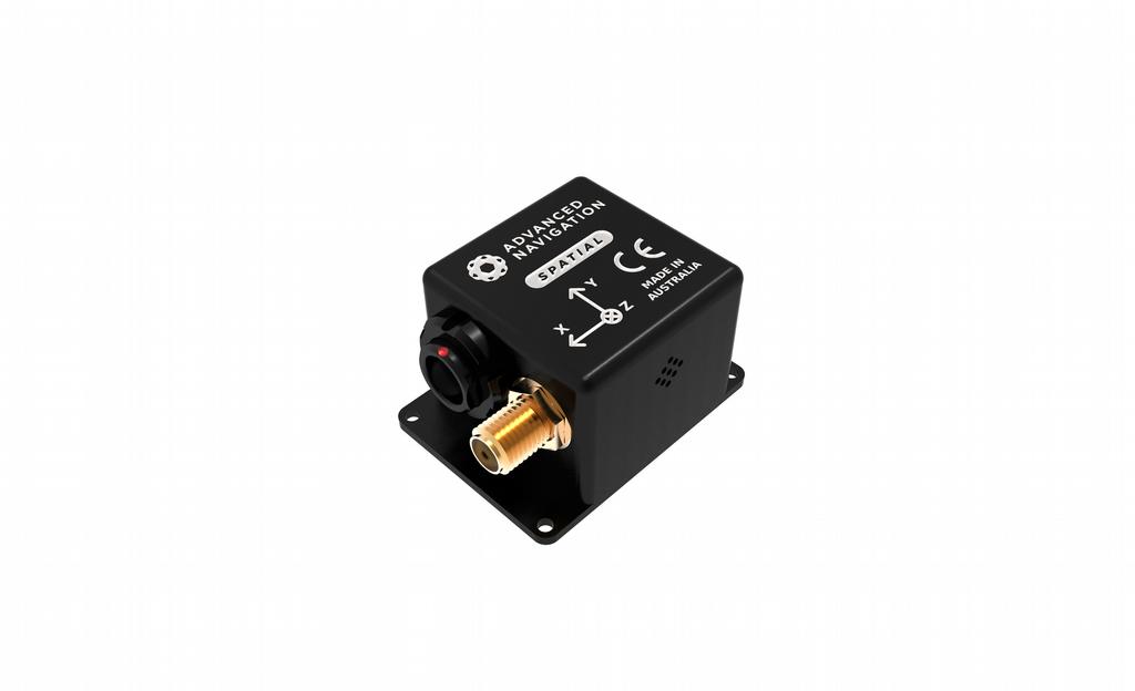
21 Page of 9 Version. //7 5.5 The Sensor Co-ordinate Frame Inertial sensors have different axes: X, Y and Z and these determine the directions around which angles and accelerations are measured. It is very important to align the axes correctly in installation otherwise the system won't work correctly. These axes are marked on the top of the device as shown in Illustration below with the X axis pointing in the direction of the connectors, the Z axis pointing down through the base of the unit and the Y axis pointing off to the right. Illustration : Spatial axes Illustration : First right hand rule When installed in an application the X axis should be aligned such that it points forwards and the Z axis aligned so that it points down when level. A good way to remember the sensor axes is the right hand rule, which is visualised in Illustration. You take your right hand and extend your thumb, index and middle. Your thumb then denotes the X axis, your index denotes the Y axis and your middle denotes the Z axis. 5.6 Roll, Pitch and Heading Orientation can be described by the three angles roll, pitch and heading, these are known as the Euler angles. The rotation axes of roll, pitch and heading are shown visually in Illustration. The arrow indicates the positive rotation direction. Roll is the angle around the X axis and is zero when the unit is level. Pitch is the angle around the Y axis and is zero when the unit is level. Heading is the angle around the Z axis and is zero when the positive X axis is pointing to true north Second Right Hand Rule The two right hand rules are often the best way to memorise the sensor axes and directions of positive rotation. The first right hand rule gives the positive axis directions and is described in section 5.5. The second right hand rule shown in Illustration provides the direction of positive rotation. To use it, point your thumb in the positive direction of that axis, then the direction that your fingers curl over is the

22 Page of 9 Version. //7 positive rotation on that axis. Illustration : Second right hand rule 5.6. Rotation Order When multiple axes are rotated, to imagine the final orientation the three rotations must be performed in the order heading first, then pitch and then roll. To deduce the final orientation the unit should first be considered level with the X axis pointing north and the Z axis pointing down. Heading is applied first, then pitch is applied and finally roll is applied to give the final orientation. This can be hard for some people to grasp at first and is often best learned experimentally by rotating spatial with your hand whilst watching the orientation plot in real time on the computer. 5.7 Geodetic Co-ordinate System The geodetic co-ordinate system is the most popular way of describing an absolute position on the Earth. It is made up of the angles latitude and longitude combined with a height relative to the ellipsoid. Latitude is the angle that specifies the north to south position of a point on the Earth's surface. Longitude is the angle that specifies the east to west position of a point on the Earth's surface. The line of zero latitude is the equator and the line of zero longitude is the prime meridian. Illustration shows how latitude and longitude angles are used to describe a position on the surface of the Earth.

23 Page of 9 Version. //7 Illustration : Latitude and longitude represented visually to describe a position Illustration 5 below shows latitude and longitude on a map of the world.
24 Page of 9 Version. //7 Equator Illustration 5: World map showing latitudes and longitudes Latitude and longitude give the D point on the surface of the Earth. These are combined with height to give the D position on the Earth. Height is the height above the WGS reference ellipsoid. The WGS reference ellipsoid is a model used to approximate sea level across the Earth. Therefore the height should be considered approximately relative to sea level. Due to the approximate nature of the WGS model, the WGS height will not be the same as the actual sea level. For example, in Australia, the WGS height at sea level is 9 metres at some points. 5. NED Co-ordinate Frame The NED (North East Down) co-ordinate frame is used to express velocities and relative positions. The origin of the co-ordinate frame can be considered the current position. From that origin, the north axis points true north and parallel to the line of latitude at that point. The east axis points perpendicular to the north axis and parallel to the line of longitude at that point. The down axis points directly down towards the centre of the Earth. See Illustration 6 for a graphical representation of the NED coordinate frame at a position on the Earth.
 co-ordinate frame is a Cartesian co-ordinate frame used to represent absolute positions on the Earth.")
25 Page of 9 Version. //7 Illustration 6: Graphic showing geodetic, NED and ECEF co-ordinates 5.9 ECEF Co-ordinate Frame The ECEF (Earth-centred earth-fixed) co-ordinate frame is a Cartesian co-ordinate frame used to represent absolute positions on the Earth. Its origin is at the centre of the Earth. ECEF is an alternative to the geodetic co-ordinate frame. It is represented by the three axes X, Y and Z which are presented graphically in Illustration 6. ECEF positions can be retrieved from Advanced Navigation products however the geodetic system is used as the default.


26 Page 5 of 9 Version. //7 6 Evaluation Kit Spatial is supplied in an evaluation kit that contains everything required to get started operating the system right away. The evaluation kit is supplied in a plastic carry case to protect the equipment during shipping. Illustration 7: Spatial Evaluation Kit 6. Evaluation Kit Contents. Spatial GNSS/INS. Rugged IP67 GPS/GLONASS/GALILEO/BeiDou GNSS antenna. Spatial connector to USB interface cable, see section. 6. Quick Start. Position the GNSS antenna in a level orientation with a clear view of the sky.. Connect the coaxial antenna cable to Spatial.. Plug the interface cable into Spatial.. Plug the USB end of the interface cable into your computer. 5. Download the Spatial Manager software from the Spatial page of the Advanced Navigation website. Java is required to run the software. Java is available from if not already installed. 6. Click the connect button in Spatial Manager. 7. The various windows in Spatial Manager can be used to view the real time data.. Once the unit is installed, perform a magnetic calibration. Please see section.5.
27 Page 6 of 9 Version. //7 9. Enter the GNSS antenna position offset into the alignment dialogue in Spatial Manager and press save, see section..5. The antenna offset is measured from the centre of the Spatial unit to the centre of the antenna in the body coordinate frame. Please note that as Z is positive down, if the antenna is above the Spatial unit this will result in a negative Z value..to view the data logs, click disconnect in Spatial Manager. In the tools menu, select log converter and press convert. The *.anpp binary log file will be converted to CSV files that can be opened with popular data processing programs such as Matlab or Microsoft Excel. The log files can be found in the same folder as the Spatial Manager software. 6. Troubleshooting. If you are having trouble opening Spatial Manager, please try reinstalling Java.. If you are having problems connecting to Spatial, please try reinstalling the latest FTDI driver from the FTDI website: If you are running Spatial at a high update rate under Windows the latency timer will need to be adjusted. To do this please open control panel system device manager ports right click USB Serial Port properties port settings advanced. In this window change the latency timer to millisecond. Please see section.. for more detail.
28 Page 7 of 9 Version. //7 7 Part Numbers and Ordering Options 7. Evaluation Kit Part Number SPATIAL-EK Spatial Evaluation Kit Notes Spatial evaluation kit Includes items listed in section 6. Table : Evaluation kit part numbers 7. Standalone Unit Part Number Notes SPATIAL Spatial Unit Spatial Unit No cables or antennas included SPATIAL- Spatial Unit (RS) Spatial Unit With optional RS interface instead of standard RS interface No cables or antennas included Table 5: Standalone unit part numbers
29 Page of 9 Version. //7 7. Accessories Part Number Notes A5-SDC796 ODU plug to FTDI Spatial ODU plug with m of cable to FTDI USB cable RS to USB plug, see section. TW7 GNSS Antenna Magnetic mount L GNSS Antenna (GPS/GLONASS/BeiDou/Galileo/SBAS) A5-SDC7-M ODU plug with m cable (unterminated) Spatial ODU plug with m of unterminated cable, see section.9 A5-SDC75 ODU to D9 connectors and DC socket Spatial ODU plug with m of cable to industry standard D9 connectors and DC socket, see section. CABLE-FTDI-DSUB- FTDI USB to RS Adapter metre FTDI USB to RS Adapter SUPPLY-V V DC Power Supply -V AC Mains (IEC socket) to V DC Power Supply (DC jack) CARVPWR Car cigarette lighter power supply Car cigarette lighter to DC jack power supply OBDII-ODOMETER OBDII Odometer OBDII Odometer Interface See section 9.6. AD-UNIT Air Data Unit Air data unit provides pitot and static air data aiding for Spatial in fixed wing aircraft ILU Interface and Logging Unit Interface and logging unit provides an ethernet interface to Spatial with built in logging, time server and more ports Table 6: Accessories part numbers
30 Page 9 of 9 Version. //7. Specifications Mechanical Drawings Illustration : Mechanical drawings of Spatial
31 Page of 9 Version. //7. Navigation Specifications Parameter Value Horizontal Position Accuracy. m Vertical Position Accuracy. m Horizontal Position Accuracy (with DGNSS).6 m Vertical Position Accuracy (with DGNSS). m Velocity Accuracy.5 m/s Roll & Pitch Accuracy (Static). Heading Accuracy (Static).5 Roll & Pitch Accuracy (Dynamic). Heading Accuracy (Dynamic with GNSS). Heading Accuracy (Dynamic, magnetic only). Heave Accuracy Orientation Range 5 % or.5 m Unlimited Hot Start Time 5 ms Internal Filter Rate Hz Output Data Rate Up to Hz Table 7: Navigation specifications
32 Page of 9 Version. //7. Sensor Specifications Parameter Accelerometers Gyroscopes Magnetometers Pressure g g 6 g 5 /s 5 /s /s G G G to KPa ug /hr - Pa < 5 mg <. /s - < Pa Initial Scaling Error <.6 % <. % <.7 % - Scale Factor Stability <.6 % <.5 % <.9 % - Non-linearity <.5 % <.5 % <. % - Cross-axis Alignment Error <.5 < ug/ Hz.5 /s/ Hz ug/ Hz.56 Pa/ Hz Hz Hz Hz 5 Hz Range (dynamic) Bias Instability Initial Bias Noise Density Bandwidth Table : Sensor specifications
33 Page of 9 Version. //7. GNSS Specifications Parameter Supported Navigation Systems Supported SBAS Systems Update Rate Value GPS L GLONASS L GALILEO E BeiDou B WAAS EGNOS MSAS GAGAN QZSS Hz Cold Start Sensitivity - dbm Tracking Sensitivity -67 dbm Hot Start First Fix s Cold Start First Fix 6 s Horizontal Position Accuracy Horizontal Position Accuracy (with SBAS).5 m m Velocity Accuracy.5 m/s Timing Accuracy ns Acceleration Limit g Table 9: GNSS specifications.5 Communication Specifications Parameter Interface Speed Protocol Peripheral Interface GPIO Level Table : Communication specifications Value RS to M baud AN Packet Protocol NMEA TSS Simrad x GPIO and Auxiliary RS 5 V
34 Page of 9 Version. //7.6 Hardware Specifications Parameter Operating Voltage Input Protection Power Consumption Value 5 to 6 V ± V 5 V (typical) Hot Start Battery Capacity > hrs Hot Start Battery Charge Time mins Hot Start Battery Endurance > years Operating Temperature - C to 5 C Environmental Sealing IP67 MIL-STD-G Shock Limit g Dimensions (excluding tabs) x x mm Dimensions (including tabs) x.6 x mm Weight Table : Hardware specifications 7 grams
35 Page of 9 Version. //7.7 Electrical Specifications Parameter Minimum Typical Maximum Power Supply Input Supply Voltage Input Protection Range 5V 6 V - V V RS Tx Voltage Low -5.7 V Tx Voltage High 5V Tx Short Circuit Current 6. V ±5 ma Rx Threshold Low. V Rx Threshold High -5 V ±7 ma. V.7 V.5 V GPIO Output Voltage Low V. V Output Voltage High. V 5V Input Voltage - V V Input Threshold Low Input Threshold High.5 V.5 V Output Current 5 ma GNSS Antenna Active Antenna Supply Voltage Antenna Supply Current Table : Electrical specifications.9 V V. V 75 ma
36 Page 5 of 9 Version. //7. Power Consumption Current Consumption (ma) Maximum Typical Voltage (V) Illustration 9: Maximum and typical current consumption across operating voltage.9 Connector Pin-out Power supply and signal connections are made through a ODU Mini-Snap Series B 9 pin connector. The ODU part number is SBSP9MCC-5. The connector provides a reliable and rugged connection to Spatial under demanding conditions and is rated to IP6 in the mated condition. Plugs are supplied with metres of unterminated shielded cable with an outer protective jacket. Each individual wire is colour coded PFA coated AWG wire with an external shield and insulation. Custom cable lengths can be ordered by request.
37 Page 6 of 9 Version. //7 Illustration : ODU B series mating plug for Spatial Pin Colour Function Black Ground Brown Power Supply White GPIO Green GPIO 5 Red Primary RS Transmit 6 Orange Primary RS Receive 7 Yellow Auxiliary RS Transmit Blue Auxiliary RS Receive 9 Pink Ground Table : Pin allocation table. Evaluation Kit USB Cable The evaluation kit is supplied with a metre cable with a Spatial ODU plug on one end and an overmoulded RS to USB converter on the other end, please see Illustration. The cable is the same 9 wire cable supplied with unterminated ODU cables and all 9 wires are connected on the ODU end. If required, it is possible to cut off the overmoulded RS converter to get access to all the individual wires. The chip used in the overmoulded RS converter is an FTDI FTR and supports baud rates of up to,, baud.
38 Page 7 of 9 Version. //7 Illustration : Evaluation kit USB cable Pin Colour Function RS Converter Connection Black Ground USB Ground Brown Power USB 5 volt supply White GPIO Green GPIO 5 Red Primary RS Tx FTDI RS Rx 6 Orange Primary RS Rx FTDI RS Tx 7 Yellow Auxiliary RS Tx Blue Auxiliary RS Rx 9 Pink Ground Table : Evaluation kit USB cable pin-out. Optional Breakout Cable Advanced Navigation offers a pre-terminated breakout cable for access to all of Spatial's pins. All external signal and power connections are provided with m of cable. The interface cable is provided with industry standard 9 pin DSUB connectors for each of the two RS communication channels and GPIO pins. The breakout cable is an optional extra and is not supplied as standard with the evaluation kit.
39 Page of 9 Version. //7 Illustration : Optional breakout cable diagram Pin Colour Function Primary Auxiliary GPIO Black Ground Brown Power White GPIO Green GPIO 5 Red Primary RS Tx 6 Orange Primary RS Rx 7 Yellow Auxiliary RS Tx Blue Auxiliary RS Rx 9 Pink Ground Power Tip Ring Table 5: Optional breakout cable connector pin-out. Sensor Calibration Spatial's sensors are calibrated for bias, sensitivity, misalignment, cross-axis sensitivity, non-linearity and gyroscope linear acceleration sensitivity across the full operating temperature range and for each of the three sensor ranges.. Serial Number The serial number can be inspected by using the device information dialogue in the Spatial Manager software, see section.7.. The primary serial number label is

40 Page 9 of 9 Version. //7 located inside the enclosure and is accessible only by Advanced Navigation technicians. The secondary serial number label is located on the outside rear of the enclosure with the serial number encoded in a D data matrix bar code to assist customers in tracking their units. The external label also contains the hardware version and build date. Applications are available for most smart-phones that can scan the D data matrix bar code to display the serial number. Illustration : Spatial external serial number label
41 Page of 9 Version. //7 9 Installation 9. Installation Checklist. Securely mount the unit to the vehicle following the guidelines in section 9... Mount the GNSS antenna to the vehicle following the guidelines in section 9.5 and then connect the antenna to Spatial unit.. Connect the connector cable to Spatial and then connect the USB end to a computer.. Open the Spatial Manager software on the computer and click connect. 5. If the unit is mounted in an alignment other than standard alignment of X pointing forward and Z pointing down, this alignment offset will need to be entered into the Alignment Configuration dialogue in Spatial Manager. Please see section 9.. for more details. 6. Accurately measure the primary GNSS antenna offset from the centre of the Spatial unit to the centre of the antenna in the body co-ordinate frame (X positive forward and Z positive down) and enter these values into the Alignment Configuration dialogue in Spatial Manager. Please note that the body axes are always X positive forward and Z positive down irrespective of any alignment offset entered in the previous step. 7. Enter the vehicle type in the Filter Options dialogue in Spatial Manager.. Perform a magnetic calibration on the unit as described in section.5. If magnetic calibration is going to be too difficult to perform on the vehicle or the operating environment has high levels of magnetic interference then it is recommended to disable magnetic heading in Filter Options and use only GNSS velocity heading. If magnetic heading is disabled a magnetic calibration does not need to be performed. 9. The system is now ready for use. 9. Position and Alignment When installing Spatial into a vehicle, correct positioning and alignment are essential to achieve good performance. There are a number of goals in selecting a mounting site in your application, these are:. Spatial should be mounted away from high levels of vibration where possible.. Spatial should be mounted in an area that is not going to exceed its temperature range.. The two vents on the sides of Spatial should not be obstructed.. If magnetic heading is going to be used, Spatial should be mounted at least.5 metres away from sources of dynamic magnetic interference i.e. high current wiring, large motors, moving steel masses and rotating or reciprocating machinery.
42 Page of 9 Version. //7 5. Spatial should be mounted close to the centre of gravity of the vehicle where possible. 6. Spatial should be mounted within several metres of the GNSS antenna where possible. 9.. Alignment The easiest way to align Spatial is by installing it with the sensor axes aligned with the vehicle axes. This means that the X axis points forward towards the front of the vehicle and the Z axis points down towards the ground. If aligning Spatial with the vehicle axes is not possible or not optimal, it may be mounted in a different alignment and the alignment offset should be configured using the Spatial Manager software, see section..5. For easy alignment, the set zero orientation button in the Spatial Manager alignment dialogue can be used to set the current orientation as the level alignment, see section..5. Please note that this will only correct for roll and pitch offsets. Any heading offset will need to be entered manually and saved after using this function. 9. Mounting Plate Spatial's mounting plate and hole guide is shown below in Illustration. The holes are designed for M cap screws. Illustration : Spatial mounting plate 9. Power Supply A high level of power supply filtering has been built into Spatial, however it is still recommended that the power supply be free of significant noise. As the communications ground is shared with the supply ground, it is important to ensure that ground wiring is routed to avoid power supply noise from other systems


43 Page of 9 Version. //7 corrupting data communications. A power supply should be selected that can provide at least the maximum current calculated from the graph in Illustration 9. Spatial contains an active protection circuit on the power supply input that protects the unit from under-voltage, over-voltage and reverse polarity events. The protection circuit shuts off power and automatically recovers the unit to full operation once the fault is removed. Take care when running the unit close to its under-voltage lockout of. V because small voltage drops can engage the under-voltage shutdown and potentially oscillate between the on and off state. It is recommended that the unit is always run at.7 V or more to avoid issues associated with this. 9.5 GNSS Antenna The GNSS antenna should be installed level with a clear unobstructed view of the sky and close to the Spatial unit where possible. The antennas should be mounted away from any RF emitters. The antenna cable should be routed away from powerful RF emitters, high current wiring, high temperatures and any rotating or reciprocating machinery. The optimum mounting configuration is above the Spatial unit. The antenna offset should be configured in the Spatial unit by using the alignment dialogue in the Spatial Manager software, see section..5. It is very important to set the antenna offset accurately as Spatial corrects for lever arm velocities. Incorrect GNSS antenna offset will lead to performance degradation under turning and angular rotations. The antenna offset is measured from the centre of the Spatial unit to the centre of the antenna in the body frame (X forward, Z down). Please note that as Z is positive down, mounting the antenna above the Spatial unit will result in a negative Z offset. An example installation with axes marked is shown below in Illustration 5 and Illustration 6. In this installation there would be a positive X antenna offset value, a positive Y antenna offset value and a negative Z offset value. Illustration 5: Spatial antenna offset isometric Illustration 6: Spatial antenna offset front view view It is important to note that most GNSS antennas contain magnets for mounting. If you
44 Page of 9 Version. //7 are using an antenna with magnets you will need to either keep it a minimum.5 metres distance away from Spatial or remove the magnets to ensure that it doesn't interfere with Spatial's magnetometers. If you are supplying your own antenna it is important to ensure that the antenna is able to receive all constellations and not just GPS, otherwise you will not achieve full performance. It is also important to select an IP67 antenna with an IP67 SMA connector, otherwise the system will not be environmentally sealed. It is recommended to use an antenna with the following characteristics: For GPS/GLONASS, a frequency range of 575 Mhz to 66 Mhz For GPS/BeiDou, a frequency range of 559 Mhz to 59 Mhz For all constellations, a frequency range of 559 Mhz to 66 Mhz Minimum gain of 5 db and maximum gain of 5 db Antenna LNA noise of < db Out of band rejection of 5 ±7 MHz 9.6 Odometer On ground vehicles, the use of an odometer input can greatly improve Spatial's navigation and orientation solution during GNSS dropouts. With a high resolution wheel encoder Spatial can be used to navigate indoors with GNSS disabled altogether. There are several different options for odometer installation which are listed below Factory VSS Signal Most road cars since 9 contain a VSS (vehicle speed sensor) signal that can be wired directly into one of Spatial's GPIO pins. The vehicle should be taken to an automotive electrician to perform the work. To setup the odometer, the appropriate GPIO pin should be set to odometer input using Spatial Manager, see section..7. The odometer pulse length must then be set either manually or automatically, please see section.9 for more information. For more information on the GPIO signals and their requirements please see section OBDII Odometer Interface For applications where it is undesirable to modify the vehicle or the system needs to be used with multiple vehicles, the OBDII odometer interface may be a better solution. OBDII is a vehicle diagnostic port standard and most vehicles from the mid 99s onwards contain an OBDII port in the drivers side foot well. Advanced Navigation produces an OBDII odometer interface that plugs into this OBDII port and feeds Spatial with odometer data over the Auxiliary RS port, please see Illustration 7. These units are priced at approximately AUD 5. Please contact Advanced Navigation sales for more information.


45 Page of 9 Version. //7 Illustration 7: Advanced Navigation OBDII Odometer 9.6. Aftermarket Wheel Speed Sensor Applications requiring very high performance are recommended to use a high precision aftermarket wheel speed sensor. Advanced Navigation recommends aftermarket wheel speed sensors from Pegasem or GMH Engineering. Illustration : Aftermarket wheel speed sensor 9.6. Radar Speed Sensor For applications requiring high performance in harsh conditions where aftermarket wheel speed sensors are not feasible, a radar speed sensor is recommended. Advanced Navigation recommends radar speed sensors from Stalker or GMH Engineering.

46 Page 5 of 9 Version. //7 Illustration 9: Radar speed sensor 9.7 Magnetics Spatial contains magnetometers which it uses to measure the Earth's magnetic field in order to determine its heading. The principle is the same as that of a compass. When operating Spatial with magnetic heading enabled, sources of magnetic interference can degrade Spatial's solution if not compensated for. There are two types of magnetic interference, these are static and dynamic. Static magnetic interference is caused by steel and other magnetic materials mounted in the vehicle. Static disturbances are easily compensated for by running a magnetic calibration, see section.5. A magnetic calibration should always be run after installation into a vehicle. Dynamic magnetic interference is generally a much bigger issue. Sources of dynamic magnetic interference include high current wiring, electric motors, servos, solenoids and large masses of steel that don't move with Spatial. Spatial should be mounted as far as possible from these interference sources. Spatial contains a special algorithm to remove the effects of dynamic magnetic interference. This is able to compensate for most typical interference sources encountered, however certain types of prolonged dynamic interference cannot be compensated for. The best way to check for dynamic magnetic interference is to use the raw sensors view in Spatial Manager and watch the magnetometer outputs whilst the vehicle is operating but stationary, see section.7.. The values should be constant, if the values are fluctuating there is dynamic magnetic interference present. If dynamic magnetic interference is causing performance problems and there is no way to mount Spatial away from the interference source, the magnetometers should be disabled, see section Vibration Spatial is able to tolerate a high level of vibration compared to other inertial systems. This is due to a unique gyroscope design and a special filtering algorithm. There is however a limit to the amount of vibration that Spatial can tolerate and large levels of vibration will cause Spatial's accuracy to degrade. When mounting Spatial to a platform with vibration there are several options. It is
47 Page 6 of 9 Version. //7 recommended to first try mounting Spatial and see whether it can tolerate the vibrations. The raw sensor view in the Spatial Manager software can give you a good idea of how bad the vibrations are, see section.7.. If the vibrations are causing the sensors to go over range you will need to increase the sensors range, see section.6. If you are unsure about your vibration level, we recommend ing a Spatial log file of the vibration to support@advancednavigation.com.au for feedback. If Spatial is unable to tolerate the vibrations there are several options:. Try to find a mounting point with less vibration.. Spatial can be mounted with M foam rubber double sided tape or a small flat piece of rubber.. Spatial can be mounted to a plate which is then mounted to the platform through vibration isolation mounts.
 all four levels will typically initialise within seconds and for a hot start (less than hours without power) all four levels will typically")
48 Page 7 of 9 Version. //7. Operation Initialisation There are four different levels of initialisation on Spatial. These are orientation, navigation, heading and time. Upon a cold start (more than hours without power) all four levels will typically initialise within seconds and for a hot start (less than hours without power) all four levels will typically initialise within seconds. The initialisation can be monitored by inspecting the status view in Spatial Manager, see section.7.. Illustration : The four initialisation levels After all four levels of initialisation, Spatial's filter takes several minutes to achieve full accuracy. It is recommended to wait two minutes after initialisation for applications requiring high accuracy... Orientation Initialisation Orientation initialisation occurs automatically upon power on and typically completes within several seconds. Once orientation initialisation is complete, the roll, pitch and angular velocity values will be valid. When Spatial starts up, it assumes that it can be in any orientation. To determine its orientation it uses the accelerometers to detect the gravity vector. Whilst this is occurring, if there are random accelerations present, these can cause an incorrect orientation to be detected. To prevent this, Spatial monitors the accelerometers and gyroscopes and restarts the orientation detection if there are sudden movements. It is however still possible under some circumstances for it to miss minor movements and start with a small orientation error. In this scenario Spatial will progressively correct the orientation error over a period of several seconds... Navigation Initialisation Navigation initialisation completes once the system has determined a starting position. The most common method of navigation initialisation is for the system to get a D GNSS fix. If the system is hot starting it will remember its position from when it was switched off and use this as the starting position. The other possibility for
49 Page of 9 Version. //7 navigation initialisation is an external position source, see section. for more information. In a situation where a GNSS fix is not available to initialise navigation, it can be initialised manually by entering a position into the position dialogue in Spatial Manager, see section... Once navigation initialisation is complete, the position, velocity and acceleration values will be valid... Heading Initialisation Heading initialisation completes once the system has determined a heading. The conditions required to determine a heading depend upon the heading source being used, see section.. If magnetic heading is enabled as a heading source the heading initialisation should complete within seconds after power on. If magnetic heading is disabled and velocity heading is used as the only heading source, the heading will initialise once the system travels at a speed of over.5 metres/second for over 5 seconds with a D GNSS fix. If the system is hot starting it will remember its heading from when it was switched off and use this as the starting heading until another source becomes available. Until the heading has been initialised, the system will not be able to navigate without a GNSS fix and the roll and pitch values will not be able to reach full accuracy... Time Initialisation Time initialisation completes once the system has determined time to an accuracy of less than microsecond. This normally occurs as soon as the GNSS receiver obtains its first fix. It is also possible to provide an external source of time, see section. for more information on external time sources. Until the time has initialised the values of unix time and formatted time that Spatial outputs will not be valid and may change.. Hot Start Spatial is the first GNSS/INS on the market with hot start functionality. This allows Spatial to start inertial navigation within 5 milliseconds and obtain a GNSS fix in as little as seconds. Spatial's hot start is always on and fully automatic. A next generation backup battery system within Spatial provides the hot start ability for more than hours without power. When Spatial hot starts it assumes that it is in the same state it was when it lost power and begins navigating from that position. The hot start also provides ephemeris, almanac and time information to the GNSS receiver which allows it to achieve a fix far more quickly than it otherwise would. When the GNSS achieves its first fix, if this position deviates from the hot start position, Spatial will jump to the new position without causing any side effects to the filter. Whilst Spatial is without power it keeps track of the time accurately to within second so that the time is immediately valid on a hot start. Spatial's hot start is of particular benefit to vehicle tracking and robotics applications. The primary benefits are immunity and fast recovery from power failure as well as fast startup time.
50 Page 9 of 9 Version. //7. Time Spatial was designed to provide a highly accurate time reference. When a GNSS fix is available Spatial's time is accurate to within 5 nanoseconds. When a GNSS fix is lost, Spatial's time accuracy typically remains within microseconds over extended time periods. When Spatial hot starts the time accuracy is typically within second immediately on startup and corrected to within 5 nanoseconds as soon as a GNSS fix is achieved. To synchronise with Spatial's high accuracy time, both the packet protocol and a PPS line must be used.. Heading Source There are three different heading sources available for Spatial. The heading source can be selected using the filter options dialogue in Spatial Manager, see section... It is possible to use multiple heading sources and this can often provide performance benefits... Magnetic Heading This is the default heading source and works well in the majority of cases. When using magnetic heading, calibration is required every time Spatial's installation changes. The downside of magnetic heading is that prolonged dynamic magnetic interference sources can cause heading errors... Velocity Heading Velocity heading works by deriving heading from the direction of velocity and acceleration. Velocity heading works well with cars, boats, fixed wing aircraft and other vehicles that don't move sideways. Velocity heading does not work with helicopters and other D vehicles. The downside of velocity heading is that heading can not be measured until the vehicle moves at a horizontal speed of over.5 metres/second with a GNSS fix. The benefits of velocity heading are that it is immune to magnetic interference and no calibration is required when Spatial's installation changes... External Heading This can be used if there is some other way to derive heading that is external to Spatial. Examples include dual antenna GNSS systems, north seeking gyroscopes, reference markers and SLAM systems. The heading must be fed into Spatial using the External Heading Packet or through the auxiliary RS..5 Magnetics Static magnetic interference is resolved through magnetic calibration and dynamic magnetic interference is compensated by a filter algorithm but should be minimised where possible through installation location. Please see section 9.7 for more information on magnetic interference. To compensate for static magnetic interference, magnetic calibration should be performed any time Spatial's installation changes. Spatial contains a dynamic magnetic compensation filter that is able to mitigate the effects of short term magnetic interference sources while in operation. For example if
51 Page 5 of 9 Version. //7 Spatial is installed in a car and the car drives over a large piece of magnetised steel, this will be compensated for. Another example is driving through a tunnel which is built from heavily reinforced concrete. It is important to note that for Spatial's dynamic magnetic compensation filter to operate correctly, Spatial needs to get a GNSS fix at least once every time it is moved more than 5km. Each time Spatial moves more than 5km the new position is stored permanently and allows Spatial to update its world magnetic model values. There are three types of magnetic calibration available, these are D calibration, D calibration and automatic calibration. D calibration involves one level rotation about the Z axis and is designed for vehicles that cannot easily or safely be turned upside down, such as full size cars, planes and boats. D calibration involves rotating through all orientations and is designed for vehicles that can easily and safely be rotated upside down, such as model size vehicles. D calibration offers slightly better performance and is recommended where possible. Automatic magnetic calibration continuously and automatically calibrates for static magnetic interference while the unit is in operation. It is not as accurate as the D or D calibration, however it is very convenient for applications where Spatial needs to just work without user intervention. Please note that if Spatial is going to be used in a vehicle, the calibration should be performed while Spatial is mounted in and fixed to that vehicle. This means that the whole vehicle must be moved to perform the calibration. The calibration needs to be performed in an area away from sources of magnetic interference. For example if Spatial is installed in a car, the calibration should not involve driving over steel drains or reinforced concrete etc. If Spatial is being calibrated to operate standalone, the calibration should not be done on a desk with a steel frame..5. D Magnetic Calibration The following procedure should be used to perform a D magnetic calibration..5.. Using the Spatial Manager Software. The unit should be powered on while the vehicle is in a level orientation and kept stationary.. After power on wait 5 minutes for the temperature and filter to stabilise.. Open Spatial Manager and connect to the device. Ensure that the device has a GNSS fix before proceeding.. In the Tools menu, open Magnetic Calibration. Click the D Calibration button. See section Whilst keeping as level as possible, rotate the vehicle in either direction through one and a quarter full rotations. In a car this can be achieved by driving in one and a quarter circles. 6. Check the status in the Magnetic Calibration window to ensure that the calibration completed successfully. If not successful click Cancel, wait minutes and repeat from step. Do not press the save button in the lower half of the dialogue, this will over write the new calibration values. The calibration values are automatically saved internally.
52 Page 5 of 9 Version. //7.5.. Using the Packet Protocol. The unit should be powered on while the vehicle is in a level orientation and kept stationary.. After power on wait 5 minutes for the temperature and filter to stabilise.. Ensure that the device has a GNSS fix before proceeding. Send the Magnetic Calibration Configuration Packet with the action Start D Magnetic Calibration. 5. Whilst keeping as level as possible, rotate the vehicle in either direction through one and a quarter full rotations. In a car this can be achieved by driving in one and a quarter circles. 6. Read the Magnetic Calibration Status Packet to ensure that the calibration completed successfully. If not successful, send the Magnetic Calibration Configuration Packet with the action Cancel, wait minutes and repeat from step..5. D Magnetic Calibration The following procedure should be used to perform a D magnetic calibration..5.. Using the Spatial Manager Software. The unit should be powered on and the vehicle kept stationary.. After power on wait 5 minutes for the temperature and filter to stabilise.. Open Spatial Manager and connect to the device. Ensure that the device has a GNSS fix before proceeding.. In the Tools menu, open Magnetic Calibration. Click the D Calibration button. See section.9.. The following steps 5, 6 and 7 can be performed in any order. 5. Slowly rotate the vehicle twice around the X axis (roll). 6. Slowly rotate the vehicle twice around the Y axis (pitch). 7. Slowly rotate the vehicle twice around the Z axis (heading).. Check the status in the Magnetic Calibration window to ensure that the calibration completed successfully. If not successful click Cancel, wait minutes and repeat from step. Do not press the save button in the lower half of the dialogue, this will over write the new calibration values. The calibration values are automatically saved internally..5.. Using the Packet Protocol. The unit should be powered on and the vehicle kept stationary.. After power on wait 5 minutes for the temperature and filter to stabilise.. Ensure that the device has a GNSS fix before proceeding. Send the Magnetic Calibration Configuration Packet with the action Start D
53 Page 5 of 9 Version. //7 Magnetic Calibration. The following steps 5, 6 and 7 can be performed in any order. 5. Slowly rotate the vehicle twice around the X axis (roll). 6. Slowly rotate the vehicle twice around the Y axis (pitch). 7. Slowly rotate the vehicle twice around the Z axis (heading). Read the Magnetic Calibration Status Packet to ensure that the calibration completed successfully. If not successful, send the Magnetic Calibration Configuration Packet with the action Cancel, wait minutes and repeat from step..5. Automatic Magnetic Calibration Automatic magnetic calibration is an algorithm that continuously and automatically calibrates for static magnetic interference. Automatic magnetic calibration is enabled by default and it is recommended to keep it enabled for all vehicle types. When used on top of a D or D calibration it can give the best results from magnetic heading. Every time Spatial is powered on in a cold start ( hours without power) the automatic calibration is reset. The automatic magnetic calibration starts operating when Spatial is travelling at a speed over 5 m/s with a GNSS fix and velocity heading turned on. Automatic magnetic calibration is not as accurate as D or D calibration, however it is sufficient for most vehicles and allows Spatial to be installed into vehicles and operated without user intervention. Automatic magnetic calibration can be turned off using the filter options dialogue in Spatial Manager, see section Disabling Magnetometers In situations where there is very strong dynamic magnetic disturbances present, it is recommended to disable the magnetometers. When the magnetometers are disabled a secondary heading source is required otherwise may become inaccurate. Velocity heading is the recommended source. Please see section. for information on heading sources. The magnetometers can be disabled using the filter options dialogue in Spatial Manager, see section....6 Sensors Range Spatial supports dynamic ranging on its sensors. Each of the three sensors have three different range levels. At lower ranges the sensor performance is better, but at higher ranges Spatial can be used in more extreme dynamics. It is important to choose a range that your application won't exceed. Sensor over range events can be detected through the Filter Status. In Spatial manager the status indicator will go orange indicating that a sensor has gone over range. When a sensor goes over range this causes the filter solution to become inaccurate and in some cases it can cause the filter to reset. By default Spatial comes configured in the lowest sensor ranges. In this configuration it is possible to send the gyroscopes over range by quickly rotating the unit in your hand. It is recommended to watch what happens in Spatial Manager when you do this. The sensor ranges can be set through the sensor ranges dialogue in the configuration
54 Page 5 of 9 Version. //7 menu in Spatial Manager, see section....7 Data Anti Aliasing Internally Spatial's filters update at Hz. When Spatial outputs data, most applications require the data at a much lower rate (typically < Hz). This causes a problem for time based data such as velocities and accelerations where aliasing will occur at the lower rate. To prevent this problem, if the output rate is lower than Hz, Spatial will low pass filter the values of the time dependent data between packets to prevent aliasing. This is only the case when a packet is set up to output at a certain rate. If the packet is simply requested no anti aliasing will occur. Additionally there is no anti aliasing for non time dependent fields such as position.. Vehicle Profiles Spatial supports a number of different vehicle profiles. These vehicle profiles impose constraints upon the filter that can increase performance. If your application matches one of the available vehicle profiles, it is recommended to select it for use in the filter options dialogue in Spatial Manager, see section... For a list of the different vehicle profiles please see section..6.. Please note that if the wrong vehicle profile is selected it can cause a significant decrease in performance..9 Odometer Pulse Length For Spatial to use a wheel speed sensor or odometer input, it must know the pulse length of the signal. The pulse length is the distance in metres between low to high transitions of the signal. The odometer pulse length can either be entered manually or automatically calibrated by Spatial. To enter the pulse length manually, please use the odometer configuration dialogue in Spatial Manager, see section... To automatically calibrate the odometer pulse length please use the procedure listed below in section.9.. By default the odometer will automatically calibrate itself..9. Odometer Automatic Pulse Length Calibration Procedure. Ensure that the signal is connected correctly and that the GPIO pin is configured as an odometer input using the GPIO configuration dialogue in Spatial Manager, see section..7.. Open Spatial Manager, connect to Spatial and open the odometer configuration dialogue, see section... In the odometer configuration dialogue tick the automatic pulse length calibration check box and press the save button.. Wait until Spatial has a continuous GNSS fix and then drive metres over flat terrain with as little turning as possible.. If Spatial loses a GNSS fix for more than several seconds during the calibration, the distance travelled will be reset. The distance travelled can be checked in the odometer configuration dialogue to ensure that it has passed m. 5. Once metres has been driven, check that the automatic pulse length check box becomes un-ticked and the pulse length value has changed. This indicates a successfully completed calibration.
55 Page 5 of 9 Version. //7. Reversing Detection Reversing detection is an algorithm that can detect when the vehicle is travelling in reverse. Knowledge of reverse motion is important when using velocity heading or odometer input to provide correct results. If Spatial is fitted to a vehicle that does not reverse or doesn't use velocity heading or odometer, this function should be disabled. For all other applications it is best to leave it enabled. Reversing detection is enabled by default and it can be disabled using the filter configuration window in Spatial Manager, see section.... Motion Analysis Motion analysis is an artificial intelligence algorithm that associates patterns in high frequency inertial data with the speed of the vehicle. After power on it takes some time to match patterns with speed before it will become active. Motion analysis only activates when dead reckoning and is most effective when the vehicle is moving slowly or stationary. Motion analysis does not work in all situations and its primary benefit is in ground vehicles. It should be enabled in any car application. When active it can be recognised by Hz steps in velocity data. Motion analysis is disabled by default and can be enabled using the filter configuration window in Spatial Manager, see section.... Differential GNSS Spatial supports receiving differential GNSS corrections to enhance position accuracy. Differential corrections must come from a base station located within a km radius of where the Spatial unit is operating. There are many companies worldwide that provide nationwide network corrections services where differential corrections from a local station can be received over the internet using a protocol called NTRIP. Spatial Manager has an NTRIP client built in that can connect to the network corrections service to receive the differential corrections and feed them into the Spatial unit. Please see section.9.5. The differential corrections format supported is RTCM v. SC-. The supported messages are,, and 9.. Raw Satellite Data Spatial hardware version 6. and above features a new GNSS receiver that is capable of outputting raw satellite data. This raw satellite data can be used by post-processing programs to achieve high accuracy kinematic positioning. The maximum output rate for raw satellite data is Hz and it can be enabled by turning on the Raw Satellite Data Packet (ID 6) in the packet rates dialogue in Spatial Manager, see Illustration. This packet will be automatically converted to RINEX v. by Spatial Managers log converter utility.

56 Page 55 of 9 Version. //7 Illustration : Enabling packet 6. Post Processing Spatial hardware version 6. and above can be used with Advanced Navigation s post processing platform Kinematica to achieve high accuracy kinematic positioning of mm and significantly improved dead reckoning performance. To configure Spatial for use with Kinematica please follow the steps below.. Connect to your device using Spatial Manager.. Ensure your GNSS offset and any alignment offset has been entered as per the installation checklist in section 9... Open the Baud Rates dialogue under the Configuration menu and set the primary port baud rate to,,. See Illustration. If you are using Windows ensure you have adjusted the latency settings for the serial port as detailed in section.... Open the Packet Rates dialogue under the Configuration menu and set up the packets as shown in Illustration.

57 Page 56 of 9 Version. //7 Illustration : Spatial post processing configuration For more information on using Kinematica, please see the Kinematica Reference Manual available for download from the Advanced Navigation website..5 Vents Spatial contains a sophisticated venting system that allows it to measure air pressure whilst keeping water out. There are two sets of vent holes on either side of the enclosure. It is very important that these remain clean and clear of debris. Should debris get into the vents they should be rinsed with fresh water. Foreign bodies should never be poked into the vent holes, this will break the environmental seal and void the warranty on the unit..6 RAIM RAIM stands for receiver autonomous integrity monitoring. It allows a GNSS receiver to detect and exclude both faulty and fraudulent satellite signals. Spatial's internal GNSS is equipped with RAIM and it is enabled by default..7 Heave Spatial can provide vertical heave position at four different points on a ship. Spatial's heave filter is always on and fully automatic. After power on, Spatial requires approximately 5 minutes for its heave filter to converge upon an accurate solution. Heave works without a GNSS fix, however best heave performance is achieved when Spatial has a GNSS fix. By default Spatial provides heave from the point at which the Spatial unit is mounted, however it can provide heave at four different offset points on the ship. To set the heave offsets, either use the heave configuration dialogue in Spatial Manager, see section...
58 Page 57 of 9 Version. //7. Environmental Exposure Whilst Spatial is environmentally protected, there are clearly defined limits to this protection that must be adhered to for reliable operation. Spatial is only protected when its connector is mated and an IP67 SMA GNSS antenna is attached to it. When either of these two connections are not finger tightly closed the unit offers no environmental protection. Spanners or tools should never be used to tighten the connectors. They should only ever be finger tight... Temperature Spatial should not be subjected to temperatures outside of its operating range. If the temperature rises above 9 degrees Celsius, Spatial will automatically shut off power to its sensors and GNSS in an attempt to prevent damage, this will also send the filters into reset. Subjecting Spatial to temperature's outside of the storage range can effect the factory sensor calibration which will cause a permanent performance degradation... Water Spatial is water-proof to the IP67 standard which means that it can be submersed in water to a depth of up to metre only. Submersion to depths beyond metre can cause water entry and destruction of the internal electronics... Salt Spatial is made from marine grade aluminium which gives it reasonably good salt water corrosion resistance. However Spatial cannot tolerate extended periods of time in salt water environments. After any contact with salt water environments, Spatial should be thoroughly rinsed with fresh water... Dirt and Dust Spatial is completely sealed against dirt and dust entry. It is important to note that this is only the case when the connectors are mated. When un-mating the connectors if the Spatial unit is dirty or dusty, the dirt should be rinsed off with fresh water first and then dried off. This is to prevent dirt or dust entering the connectors which can cause them to fail...5 PH Level Environments with a high or low PH level can cause the Spatial enclosure to corrode. If Spatial comes into contact with these environments it should be rinsed in fresh water as soon as possible. It is not recommended to operate Spatial in non neutral PH environments...6 Shocks Spatial can tolerate shocks to g, however continuous shocks of this severity are likely to cause premature failure. Shocks above g can effect the factory sensor
59 Page 5 of 9 Version. //7 calibration and degrade performance. Normally shocks to Spatial when mounted in a vehicle are fine. Even a high speed car crash is likely to reach a peak of only 5g. Shocks directly to Spatial's enclosure can more easily go over the limit however so care should be taken when handling the unit prior to mounting.
60 Page 59 of 9 Version. //7 Spatial Manager Spatial Manager is a software tool provided by Advanced Navigation for logging, testing, display and configuration of Spatial. It is designed to be simple and easy to use. Illustration : Screenshot of Spatial Manager
61 Page 6 of 9 Version. //7. Software Changelog Version Date Changes.5 //7 Internet based hot start functionality added Configuration export now contains device information. //6 Extended NTRIP support for older versions Log converter now outputs a KML file for Google Earth with detailed information as well as the GPX file Added serial port passthrough tool. 7//5 Spatial Manager now requests all configuration upon connection Spatial Manager converts any configuration packets found in ANPP log files into text Bug fix for NTRIP invalid connection. 5//5 Added network connection capability, section.9.6 Added NTRIP client, section.9.5 Two new satellite views in satellites dialogue, section.7. Added gimbal configuration dialogue, section.7. Heave offsets changed to reference point offsets, section.. Fixed issue with locales that use commas instead of decimal points in floating point numbers GPX export now vectorises paths to minimise points for better performance in Google Earth.. /9/ Improvements to the D map Support for more graphics cards Status display now shows when heading not initialised Orientation standard deviation graph added Latitude and longitude now show in position dialogue D model dialogue added, section.7. Communications dialogue added, section.7.9 Added GPIO output configuration dialogue, section.. Added position configuration dialogue, section... /9/ Significantly reduced CPU usage Minor interface enhancements New options added to filter options dialogue Added NMEA output configuration dialogue Added position configuration dialogue, section. 7// Minor interface enhancements Updated GPIO functions Detailed satellites dialogue updated to show frequencies Experimental post-processing log export function added. // Added Chinese language translation Changed logging system to binary format
62 Page 6 of 9 Version. //7 Added heave offset dialogue Firmware date added to firmware update dialogue Minor changes. // Added odometer configuration dialogue Added log converter tool Spatial Manager will now disconnect automatically if USB serial port is removed Firmware update will now change the baud rate automatically when entering bootloader mode Alignment configuration dialogue updated. 6/9/ Mac disconnect issue resolved.5 // Initial Release Table 6: Spatial Manager software changelog. System Requirements The software includes a D mapping display which requires a modern D graphics card and up to date drivers to run. If your machine does not meet the graphics requirements the mapping view will only show space without a globe. When Spatial is running at very high output rates e.g. Hz, Spatial Manager can consume significant system resources handling the large quantity of data.. Installation Spatial Manager does not need to be installed and can be run from any directory by double clicking on it. Spatial Manager requires a recent version of Java, available at On some systems to open the program it may be necessary to right click and select open with Java Runtime Environment. Both the Spatial evaluation kit and the Spatial OEM development kit make use of an FTDI USB device. The drivers are normally installed automatically, if not they are available from Troubleshooting Please contact support@advancednavigation.com.au if you are having issues... All Platforms If the globe does not appear in the D map area, this indicates that either your graphics card is not powerful enough or your graphics card driver is out of date... Windows There is a well known problem with USB serial devices under Windows known as crazy mouse. The problem occurs when the system mistakenly installs the USB serial device as a mouse. Unfortunately Microsoft has not fixed this problem in over 5 years, so it probably won't be fixed. If you experience this problem, often a restart will
63 Page 6 of 9 Version. //7 resolve it. Otherwise there is a tool available at that can fix the issue. If the serial port does not show up when you plug in your Spatial USB device, you may need to install the drivers from If you experience a blue screen of death whilst using Spatial Manager, this is typically a problem associated with older FTDI drivers. To resolve the problem, install the latest drivers from When operating Spatial at a very high data rate, data can be lost due to the latency of the FTDI driver. To resolve this problem the latency of the driver should be reduced by going to control panel system device manager ports and right click on the USB serial port, then click properties. In the properties window click the port settings tab and then the advanced button. You then need to change the latency timer setting to ms. Please see the screenshot in Illustration.

64 Page 6 of 9 Version. //7 Illustration : Screenshot of latency timer setting.. Linux If serial ports do not show up, the typical cause is permissions. The user should add themselves to the dialout group with the command sudo adduser username dialout. Compiz causes issues with the D mapping. If you are experiencing problems it is recommended to turn off compiz. Modemmanager can also sometimes cause problems on Linux installations. If you are not using a modem, it is recommended to remove modemmanager with the command sudo apt-get remove modemmanager. Spatial Manager is able to run on the OpenJDK JRE but it uses significantly more system resources than when it is running on the Oracle JRE.

65 Page 6 of 9 Version. //7.5 Main View Illustration 5: Screenshot of Spatial Manager main view.5. Serial Port The serial port dialogue is used to connect to Spatial. You should select a serial port and baud rate and click connect. The default baud rate of Spatial is 5. The connection indicator displays whether there is communication with a Spatial unit..5. Attitude Indicator The aircraft style attitude indicator shows roll and pitch through a virtual horizon. Around the sides heading, speed and height are shown. All units are SI (metric) and degrees..5. Status Indicator The status indicator section contains a Spatial status indicator, a fix indicator and a
66 Page 65 of 9 Version. //7 satellites table..5.. Spatial Status Indicator This indicator shows any problems with Spatial. Before a GNSS fix is achieved it will show the status Filter not initialised. Once the filter has initialised it should show Healthy. Clicking on the indicator will show the detailed status flags..5.. Fix Indicator This shows the status of the GNSS fix. Under normal operating conditions it should show either D Fix or SBAS Fix. When satellite visibility is poor it may show either D Fix or No Fix..5.. Satellites Table The satellites table shows the number of active satellites being used in the current GNSS solution. More detailed information can be found in the satellites view, see section D Map The D map shows Spatial's position on the Earth as well as a red trail of position history. When the filter initialises the map will automatically reset the view to Spatial's location. To move the camera click and drag on the map. To zoom in and out use the scroll wheel. To change the camera view angle right click and drag or shift click and drag D Map Controls Reset View This resets the map view to Spatial's current position Clear History This clears the current position history, this is the red trail shown on the map..6 Logging Spatial Manager features a fully automatic logging system. Every time the serial port connect button is clicked Spatial Manager starts a new log file in either the current directory or the user's home directory. The log file is given the file name SpatialLog_date_time.anpp and contains all of the raw data received from Spatial in the AN packet protocol. The log files are closed when the serial port is disconnected. To convert these log files into easily accessible formats, the log converter dialogue in the tools menu can be used, see section.9.. The log converter dialogue creates a folder and generates files in the CSV (comma separated values) format that can be easily opened with Microsoft Excel, Matlab, LibreOffice and most other data analysis programs. It also creates a GPX file of position that is designed to be opened with


67 Page 66 of 9 Version. //7 Google Earth. Illustration 6: Screenshot showing log file and log conversion folder.7 View Menu The view menu contains a number of different options for viewing data from Spatial. Illustration 7: Screenshot of Spatial Manager view menu


68 Page 67 of 9 Version. //7.7. Device Information Device information is useful during technical support and for tracking your serial number, firmware and hardware version. Illustration : Screenshot of Spatial Manager device information dialogue.7. Status Status shows Spatial's complete status as contained in the system state packet detailed in section.9... Illustration 9: Screenshot of Spatial Manager status dialogue

69 Page 6 of 9 Version. //7.7. Satellites Satellites shows detailed information on the satellites that Spatial's GNSS receiver is tracking. Illustration : Screenshot of Spatial Manager satellites dialogue

70 Page 69 of 9 Version. //7.7. Raw Sensors Raw sensors shows the temperature calibrated raw sensor values. Illustration : Screenshot of Spatial Manager raw sensors dialogue

71 Page 7 of 9 Version. //7.7.5 Orientation Orientation shows Spatial's orientation and angular velocity. Illustration : Screenshot of Spatial Manager orientation dialogue

72 Page 7 of 9 Version. //7.7.6 Position Position shows Spatial's position and position error. Latitude and longitude are converted to North and East metres from a reference point that can be reset. Illustration : Screenshot of Spatial Manager position dialogue

73 Page 7 of 9 Version. //7.7.7 Velocity and Acceleration Velocity and Acceleration shows Spatial's velocity, acceleration and g-force. Illustration : Screenshot of Spatial Manager velocity and acceleration dialogue


74 Page 7 of 9 Version. //7.7. D Model Illustration 5: Screenshot of Spatial Manager D model dialogue.7.9 Communications Statistics Illustration 6: Screenshot of Spatial Manager communications statistics dialogue

75 Page 7 of 9 Version. //7.7. Heave Illustration 7: Screenshot of Spatial Manager heave dialogue


76 Page 75 of 9 Version. //7. Configuration The configuration menu contains a number of dialogues for the configuration of Spatial. Illustration : Screenshot of Spatial Manager configuration menu.. Configuration Export The configuration export dialogue can be used to export all Spatial settings to a file. This file can be imported at a later date or on other units. This is useful to restore a unit to preset configuration at a later date or for batch configuration of multiple units. Illustration 9: Screenshot of Spatial Manager configuration export dialogue


77 Page 76 of 9 Version. //7.. Sensor Ranges The sensor ranges dialogue is used to set the dynamic range of the sensors. If you are experiencing over-range events during operation this dialogue should be used to increase the range of the offending sensor. The lowest ranges give the best performance so it is preferable not to use the highest range by default. Illustration : Screenshot of Spatial Manager sensor ranges dialogue.. Filter Options For most applications the default filter options should be used and only the vehicle profile set. If in doubt please contact support@advancednavigation.com.au. Illustration : Screenshot of Spatial Manager filter options dialogue
 and the Raw Sensors Packet (ID ) at Hz and these typically provide all the data that a user will require.")
78 Page 77 of 9 Version. //7.. Packet Rates The packet rates dialogue allows the user to specify which packets output on a periodic basis and at what rate. The default packets enabled are the System State Packet (ID ) and the Raw Sensors Packet (ID ) at Hz and these typically provide all the data that a user will require. These two packets need to be enabled for the data graphs to update in Spatial Manager. Other state packets can be enabled as required. Please see the Packet Summary table in section.7 for a list of all packets. Illustration : Screenshot of Spatial Manager packet rates dialogue

79 Page 7 of 9 Version. //7..5 Alignment Configuration The alignment configuration dialogue is used to set the alignment offsets of the system installation. It is important to set the values in this dialogue correctly for accurate results. For most applications only the GNSS antenna offset values need to be entered and the rest of the values can be left at their factory defaults of zero. Illustration : Screenshot of Spatial Manager alignment configuration dialogue..5. Alignment Offset If Spatial is installed into the vehicle with the X axis pointing forwards and the Z axis pointing down, then no alignment offset is required and the roll, pitch and heading offset values can remain at the factory defaults of zero. If the unit is installed in a different orientation then the roll, pitch and heading offset must be entered. For example if the unit is installed on its side with the X axis pointing up and the Z axis pointing forwards and no change to the Y axis, then this would result in a pitch offset of +9 degrees with roll and heading remaining zero. If there is a small misalignment due to mechanical mounting error this can be compensated for by setting the vehicle stationary on a level surface and pressing the zero current orientation button. Please note that this will only correct for roll and pitch offsets, the heading offset must be entered manually and saved after using this function. All the other offsets will be measured in the realigned body co-ordinate frame (X positive forward, Z positive down) after being corrected for any alignment offset entered...5. GNSS Antenna Offset The GNSS antenna offset is measured from the centre of the Spatial unit to the centre

80 Page 79 of 9 Version. //7 of the antenna in the body co-ordinate frame (X positive forward, Z positive down)...5. Odometer Offset The odometer offset is measured from the centre of the Spatial unit to the point at which the vehicle's tyre makes contact with the road in the body co-ordinate frame (X positive forward, Z positive down)...5. External Data Offset These values are only required for speciality applications operating with external sources of data. Please contact support@advancednavigation.com.au for assistance with these values...6 Baud Rates When changing baud rates, some Microsoft Windows machines are unable to function at the higher baud rates. It is recommended to test the baud rate first with the permanent box unticked. This way, if it is not possible to communicate at the higher baud rate, a power cycle can be used to revert to the previous baud rate. Illustration : Screenshot of Spatial Manager baud rates dialogue


81 Page of 9 Version. //7..7 GPIO Configuration This dialogue allows the user to select the function of the GPIO pins and Auxiliary RS. These functions change dynamically and are effective immediately upon pressing save. Please note that GPIO pins function at RS levels for data functions and to 5 volt levels for all other functions. The internal hardware automatically reconfigures based upon the selected function. Illustration 5: Spatial Manager GPIO configuration dialogue.. Odometer The odometer dialogue allows the user to configure the odometer pulse length and view the real time odometer data to verify correct operation. Illustration 6: Screenshot of Spatial Manager odometer configuration dialogue


82 Page of 9 Version. //7..9 Reset The reset button causes the system to perform a power cycle as if the unit had the power removed and reapplied. The factory restore button causes the system to erase all settings and restore factory defaults. It also erases the hot start data so that the system is forced to perform a cold start. Illustration 7: Screenshot of Spatial Manager reset dialogue.. Reference Position Offsets The reference point offsets dialogue allows the user to adjust the point of measurement away from its default position at the centre of the Spatial unit. The primary reference point offset applies to data from all ANPP packets as well as all peripheral output such as NMEA and heave point. The heave points to allow the user to offset reference points for the heave values to in the Heave Packet. Illustration : Screenshot of Spatial Manager reference position offsets dialogue

83 Page of 9 Version. //7.. GPIO Output Configuration The GPIO output configuration dialogue allows the user to configure the output rates for the GPIO and Auxiliary RS data functions NMEA, TSS and PASHR. Illustration 9: Screenshot of Spatial Manager GPIO output configuration dialogue

84 Page of 9 Version. //7.. Manual Initialisation This dialogue can be used to manually initialise Spatial when a GNSS fix is not available. Setting the position will initialise the navigation filter. Setting the heading will initialise the heading. Illustration 5: Screenshot of Spatial Manager manual initialisation dialogue


85 Page of 9 Version. //7.. Gimbal The gimbal configuration dialogue is only used in speciality gimbal applications. Please contact support@advancednavigation.com.au for more information on using Spatial inside a gimbal. Illustration 5: Screenshot of Spatial Manager gimbal dialogue.9 Tools The tools menu contains tools for performing procedures with Spatial. Illustration 5: Screenshot of Spatial Manager tools menu.9. Terminal The terminal is only used during specialised technical support with Advanced Navigation engineers.

86 Page 5 of 9 Version. //7.9. Magnetic Calibration The magnetic calibration dialogue allows the user to perform magnetic calibration as well as view and modify the magnetic calibration values. The actual magnetic calibration is performed inside the Spatial unit. This dialogue does not have any smarts, it is just a control and display interface. Illustration 5: Screenshot of Spatial Manager magnetic calibration dialogue


87 Page 6 of 9 Version. //7.9. Firmware Update The firmware update dialogue is used to update Spatial's firmware. Advanced Navigation firmware files have the extension.anfw. The dialogue shows the version number of the firmware file along with the date and time it was generated by engineering. Illustration 5: Screenshot of Spatial Manager firmware update dialogue.9. Log Converter This tool allows the user to convert Spatial log files into various standard formats that are readable by many programs. The offset is used to project the exported position to a point other than the centre of the Spatial unit. For most users these values should be left at zero. Illustration 55: Screenshot of Spatial Manager log converter dialogue


88 Page 7 of 9 Version. //7.9.5 NTRIP Client The NTRIP client can be used to connect to a network DGPS service to stream correction data to Spatial for DGPS. The NTRIP client requires an internet connection to function. Please contact support@advancednavigation.com.au for guidance on getting set up with network DGPS. Illustration 56: Screenshot of Spatial Manager NTRIP client dialogue.9.6 Network Connect The network connect dialogue allows Spatial Manager to make a connection to Spatial over a TCP/IP network rather than the default serial port connection. This allows Spatial to be used with ethernet to serial converters. Advanced Navigation recommends Lantronix ethernet to serial converters. Illustration 57: Screenshot of Spatial Manager network connect dialogue
Motus Reference Manual
 Page of Version. 7//6 Table of Contents 5 Revision History... Firmware Changelog... 9 Hardware Changelog... Introduction... Foundation Knowledge... 5. GNSS... 5. INS... 5. GNSS/INS... 5. AHRS... 5.5 The
Spatial Dual Reference Manual
 Spatial Dual Reference Manual Page of Version.5 /9/7 Table of Contents 5 6 7 9 Revision History... Firmware Changelog... Hardware Changelog... Introduction... Foundation Knowledge... 5 5. GNSS... 5 5.
Spatial FOG Reference Manual
 Spatial FOG Reference Manual Page of 7//6 Table of Contents 5 6 7 9 Revision History... Firmware Changelog... Hardware Changelog... Introduction... Foundation Knowledge... 5 5. GNSS... 5 5. INS... 5 5.
Spatial FOG Dual Reference Manual
 Spatial FOG Dual Reference Manual Page of Table of Contents 5 6 7 9 Revision History... Firmware Changelog... 9 Hardware Changelog... Introduction... Foundation Knowledge... 5. GNSS... 5. INS... 5. GNSS/INS...
Orientus Reference Manual
 Page of 57 Version. 5// Table of Contents Revision History... Foundation Knowledge... 5. AHRS... 5. The Sensor Co-ordinate Frame... 5. Roll, Pitch and Heading... 5.. Roll... 6.. Pitch... 6.. Heading...
Inertial Sensors. Ellipse Series MINIATURE HIGH PERFORMANCE. Navigation, Motion & Heave Sensing IMU AHRS MRU INS VG
 Ellipse Series MINIATURE HIGH PERFORMANCE Inertial Sensors IMU AHRS MRU INS VG ITAR Free 0.1 RMS Navigation, Motion & Heave Sensing ELLIPSE SERIES sets up new standard for miniature and cost-effective
Inertial Sensors. Ellipse Series MINIATURE HIGH PERFORMANCE. Navigation, Motion & Heave Sensing IMU AHRS MRU INS VG
 Ellipse Series MINIATURE HIGH PERFORMANCE Inertial Sensors IMU AHRS MRU INS VG ITAR Free 0.2 RMS Navigation, Motion & Heave Sensing ELLIPSE SERIES sets up new standard for miniature and cost-effective
Inertial Sensors. Ellipse 2 Series MINIATURE HIGH PERFORMANCE. Navigation, Motion & Heave Sensing IMU AHRS MRU INS VG
 Ellipse 2 Series MINIATURE HIGH PERFORMANCE Inertial Sensors IMU AHRS MRU INS VG ITAR Free 0.1 RMS Navigation, Motion & Heave Sensing ELLIPSE SERIES sets up new standard for miniature and cost-effective
GPS-Aided INS Datasheet Rev. 3.0
 1 GPS-Aided INS The Inertial Labs Single and Dual Antenna GPS-Aided Inertial Navigation System INS is new generation of fully-integrated, combined GPS, GLONASS, GALILEO, QZSS, BEIDOU and L-Band navigation
GPS-Aided INS Datasheet Rev. 2.3
 GPS-Aided INS 1 The Inertial Labs Single and Dual Antenna GPS-Aided Inertial Navigation System INS is new generation of fully-integrated, combined L1 & L2 GPS, GLONASS, GALILEO and BEIDOU navigation and
GPS-Aided INS Datasheet Rev. 2.7
 1 The Inertial Labs Single and Dual Antenna GPS-Aided Inertial Navigation System INS is new generation of fully-integrated, combined GPS, GLONASS, GALILEO, QZSS and BEIDOU navigation and highperformance
GPS-Aided INS Datasheet Rev. 2.6
 GPS-Aided INS 1 GPS-Aided INS The Inertial Labs Single and Dual Antenna GPS-Aided Inertial Navigation System INS is new generation of fully-integrated, combined GPS, GLONASS, GALILEO and BEIDOU navigation
3DM-GX4-45 LORD DATASHEET. GPS-Aided Inertial Navigation System (GPS/INS) Product Highlights. Features and Benefits. Applications
 Product Highlights. Features and Benefits. Applications") LORD DATASHEET 3DM-GX4-45 GPS-Aided Inertial Navigation System (GPS/INS) Product Highlights High performance integd GPS receiver and MEMS sensor technology provide direct and computed PVA outputs in a
LORD DATASHEET 3DM-GX4-45 GPS-Aided Inertial Navigation System (GPS/INS) Product Highlights High performance integd GPS receiver and MEMS sensor technology provide direct and computed PVA outputs in a
1 General Information... 2
 Release Note Topic : u-blox M8 Flash Firmware 3.01 UDR 1.00 UBX-16009439 Author : ahaz, yste, amil Date : 01 June 2016 We reserve all rights in this document and in the information contained therein. Reproduction,
Inertial Systems. Ekinox Series TACTICAL GRADE MEMS. Motion Sensing & Navigation IMU AHRS MRU INS VG
 Ekinox Series TACTICAL GRADE MEMS Inertial Systems IMU AHRS MRU INS VG ITAR Free 0.05 RMS Motion Sensing & Navigation AEROSPACE GROUND MARINE EKINOX SERIES R&D specialists usually compromise between high
Inertial Navigation System
 Apogee Series ULTIMATE ACCURACY MEMS Inertial Navigation System INS MRU AHRS ITAR Free 0.005 RMS Motion Sensing & Georeferencing APOGEE SERIES makes high accuracy affordable for all surveying companies.
SPEEDBOX Technical Datasheet
 SPEEDBOX Technical Datasheet Race Technology Limited, 2008 Version 1.1 1. Introduction... 3 1.1. Product Overview... 3 1.2. Applications... 3 1.3. Standard Features... 3 2. Port / Connector details...
xoem500 Hardware Integration Manual Inertial and GNSS measurement system Confidently. Accurately.
 xoem500 xf Inertial and GNSS measurement system Hardware Integration Manual Confidently. Accurately. Table of contents Introduction 5 Related documents 6 Precautions 7 Compliance testing 7 Hardware description
Inertial Navigation System
 Apogee Marine Series ULTIMATE ACCURACY MEMS Inertial Navigation System INS MRU AHRS ITAR Free 0.005 RMS Navigation, Motion & Heave Sensing APOGEE SERIES makes high accuracy affordable for all surveying
GNSS Compass Reference Manual
 GNSS Compass Reference Manual Page of Version. // Table of Contents 6 7 9 Revision History... Firmware Changelog... 6 Hardware Changelog... 7 Introduction... Quick Start Guide... 9. NMEA Connection....
CODEVINTEC. Miniature and accurate IMU, AHRS, INS/GNSS Attitude and Heading Reference Systems
 45 27 39.384 N 9 07 30.145 E Miniature and accurate IMU, AHRS, INS/GNSS Attitude and Heading Reference Systems Aerospace Land/Automotive Marine Subsea Miniature inertial sensors 0.1 Ellipse Series New
PPS usable by timing applications via serial port emulation
 Timing & Navigation Module z051 USB GNSS Dongle with PPS* PPS usable by timing applications via serial port emulation * The Pulse Per Second (PPS) is an electrical signal that very precisely indicates
Motion Reference Units
 Motion Reference Units MRU IP-67 sealed 5% / 5 cm Heave accuracy 0.03 m/sec Velocity accuracy 0.05 deg Pitch and Roll accuracy 0.005 m/sec 2 Acceleration accuracy 0.0002 deg/sec Angular rate accuracy NMEA
Motion Reference Units
 Motion Reference Units MRU Datasheet Rev. 1.3 IP-67 sealed 5% / 5 cm Heave accuracy 0.03 m/sec Velocity accuracy 0.05 deg Pitch and Roll accuracy 0.005 m/sec2 Acceleration accuracy 0.0002 deg/sec Angular
3DM-GX3-45 Theory of Operation
 Theory of Operation 8500-0016 Revision 001 3DM-GX3-45 Theory of Operation www.microstrain.com Little Sensors, Big Ideas 2012 by MicroStrain, Inc. 459 Hurricane Lane Williston, VT 05495 United States of
SERIES VECTORNAV TACTICAL SERIES VN-110 IMU/AHRS VN-210 GNSS/INS VN-310 DUAL GNSS/INS
 TACTICAL VECTORNAV SERIES TACTICAL SERIES VN110 IMU/AHRS VN210 GNSS/INS VN310 DUAL GNSS/INS VectorNav introduces the Tactical Series, a nextgeneration, MEMS inertial navigation platform that features highperformance
Motion & Navigation Solution
 Navsight Land & Air Solution Motion & Navigation Solution FOR SURVEYING APPLICATIONS Motion, Navigation, and Geo-referencing NAVSIGHT LAND/AIR SOLUTION is a full high performance inertial navigation solution
Attitude and Heading Reference Systems
 Attitude and Heading Reference Systems FY-AHRS-2000B Installation Instructions V1.0 Guilin FeiYu Electronic Technology Co., Ltd Addr: Rm. B305,Innovation Building, Information Industry Park,ChaoYang Road,Qi
GPS Application. Global Positioning System. We provide GPS module ODM / OEM service, any GPS receiver you want, we can provide customized services.
 GPS Application Global Positioning System We provide GPS module ODM / OEM service, any GPS receiver you want, we can provide customized services. www.win-tec.com.tw sales@win-tec.com.tw GNSS Receiver WGM-303
Hyperion NEO-M8N GPS
 Hyperion M8N GPS Product description The M8 series of concurrent GNSS modules is built on the high performing M8 GNSS engine in the industry proven NEO form factor. The M8 modules utilize concurrent reception
TACTICAL SERIES VECTORNAV INDUSTRIAL SERIES. Key Benefits Miniaturized surface mount & Rugged packaging. < 30 grams. Embedded Navigation Solutions
 TACTICAL SERIES VECTORNAV INDUSTRIAL SERIES VN100 IMU/AH AHRS VN200 GPS/INS VN300 DUAL GNSS/INS Key Benefits Miniaturized surface mount & Rugged packaging < 30 grams Embedded Navigation Solutions THE INDUSTRIAL
BW-IMU200 Serials. Low-cost Inertial Measurement Unit. Technical Manual
 Serials Low-cost Inertial Measurement Unit Technical Manual Introduction As a low-cost inertial measurement sensor, the BW-IMU200 measures the attitude parameters of the motion carrier (roll angle, pitch
OS3D-FG MINIATURE ATTITUDE & HEADING REFERENCE SYSTEM MINIATURE 3D ORIENTATION SENSOR OS3D-P. Datasheet Rev OS3D-FG Datasheet rev. 2.
 OS3D-FG OS3D-FG MINIATURE ATTITUDE & HEADING REFERENCE SYSTEM MINIATURE 3D ORIENTATION SENSOR OS3D-P Datasheet Rev. 2.0 1 The Inertial Labs OS3D-FG is a multi-purpose miniature 3D orientation sensor Attitude
1. Introduction. Quick Start Guide for GPS150 V1.02 TEL
 1. Introduction Congratulations on the purchase of your GPS150 Smart GPS/GLONASS Sensor. It is recommended that your receiver is installed by a professional installer. You will need to purchase a suitable
3DM -CV5-10 LORD DATASHEET. Inertial Measurement Unit (IMU) Product Highlights. Features and Benefits. Applications. Best in Class Performance
 Product Highlights. Features and Benefits. Applications. Best in Class Performance") LORD DATASHEET 3DM -CV5-10 Inertial Measurement Unit (IMU) Product Highlights Triaxial accelerometer, gyroscope, and sensors achieve the optimal combination of measurement qualities Smallest, lightest,
LORD DATASHEET 3DM -CV5-10 Inertial Measurement Unit (IMU) Product Highlights Triaxial accelerometer, gyroscope, and sensors achieve the optimal combination of measurement qualities Smallest, lightest,
ASC IMU 7.X.Y. Inertial Measurement Unit (IMU) Description.
 Description.") Inertial Measurement Unit (IMU) 6-axis MEMS mini-imu Acceleration & Angular Rotation analog output 12-pin connector with detachable cable Aluminium housing Made in Germany Features Acceleration rate: ±2g
Inertial Measurement Unit (IMU) 6-axis MEMS mini-imu Acceleration & Angular Rotation analog output 12-pin connector with detachable cable Aluminium housing Made in Germany Features Acceleration rate: ±2g
Underwater GPS User Manual
 Underwater GPS Document number W-DN-17002-3 Project Classification - Rev Prepared by Checked by Approved by Short description 1 2017-08-03 T. Trøite O. Skisland T. Trøite Initial 2 2017-08-04 T. Trøite
High Performance Advanced MEMS Industrial & Tactical Grade Inertial Measurement Units
 High Performance Advanced MEMS Industrial & Tactical Grade Inertial Measurement Units ITAR-free Small size, low weight, low cost 1 deg/hr Gyro Bias in-run stability Datasheet Rev.2.0 5 μg Accelerometers
FLCS V2.1. AHRS, Autopilot, Gyro Stabilized Gimbals Control, Ground Control Station
 AHRS, Autopilot, Gyro Stabilized Gimbals Control, Ground Control Station The platform provides a high performance basis for electromechanical system control. Originally designed for autonomous aerial vehicle
L76-L GNSS Module Presentation
 L76-L GNSS Module Presentation May, 2016 Quectel Wireless Solutions Co., Ltd. All rights reserved www.quectel.com Contents Highlights Advanced Features Quectel L76-L vs. Competitor s Product Support Package
RTKWARE UBR1 Technical Datasheet. ver1.1 (29/04/2015)
") RTKWARE UBR1 Technical Datasheet ver1.1 (29/04/2015) Table of Contents Table of Contents... 2 Overview... 3 Key-Features... 3 Applications... 3 Functional diagrams... 4 Power Distribution... 4 Data...
RTKWARE UBR1 Technical Datasheet ver1.1 (29/04/2015) Table of Contents Table of Contents... 2 Overview... 3 Key-Features... 3 Applications... 3 Functional diagrams... 4 Power Distribution... 4 Data...
Mini-Expansion Unit (MEU) User Guide V1.2
 User Guide V1.2") Mini-Expansion Unit (MEU) User Guide V1.2 Disclaimer Although every care is taken with the design of this product, JT Innovations Ltd. can in no way be held responsible for any consequential damage resulting
Mini-Expansion Unit (MEU) User Guide V1.2 Disclaimer Although every care is taken with the design of this product, JT Innovations Ltd. can in no way be held responsible for any consequential damage resulting
Datasheet of stand-alone GPS smart antenna module, LS20037
 Product name Description Version LS20037 Stand-alone GPS smart antenna module/mtk,9600bps 0.9 (Preliminary) Datasheet of stand-alone GPS smart antenna module, LS20037 1 Introduction LS20037 is a complete
EB-54X. EB-54X Datasheet
 GPS Engine Board EB-54X Datasheet EB-54X EB-54X is a complete GPS sub-system with 32 x 32 mm 2 In size. Equipped with antenna, back up battery GPS engine and onboard memory, it provides superior navigation
Revisions Revision Date By Changes A 11 Feb 2013 MHA Initial release , Xsens Technologies B.V. All rights reserved. Information in this docum
 MTi 10-series and MTi 100-series Document MT0503P, Revision 0 (DRAFT), 11 Feb 2013 Xsens Technologies B.V. Pantheon 6a P.O. Box 559 7500 AN Enschede The Netherlands phone +31 (0)88 973 67 00 fax +31 (0)88
SL800 GNSS RTK System User Manual
 SL800 GNSS RTK System User Manual User Manual Revision SatLab SL800 GNSS Receiver Revision Date Revision Number Description 1 st Nov 2017 1 SL800 User Manual (Release V1.0) 1 Table of Contents Introduction...
GPS6000-PRO. GNSS Time Receiver. User Manual Version 1.1
 GPS6000-PRO GNSS Time Receiver User Manual Version 1.1 COPYRIGHT 2015-2017 World Time Solutions Limited. All Rights Reserved. All information contained within this document is the property of World Time
SA-320 Installation Guide SA-320. Installation Guide. Date: Mar, 2011 Version: 2.5. All Rights Reserved
 SA-320 Installation Guide Date: Mar, 2011 Version: 2.5 All Rights Reserved Page 1 TABLE OF CONTENTS 1. Product Overview......3 1.1 Main Features...3 1.2 Applications.....3 1.3 Package Content.....3 2.
SERIES VECTORNAV INDUSTRIAL SERIES VN-100 IMU/AHRS VN-200 GPS/INS VN-300 DUAL GNSS/INS
 TACTICAL VECTORNAV SERIES INDUSTRIAL SERIES VN100 IMU/AHRS VN200 GPS/INS VN300 DUAL GNSS/INS VectorNav presents the Industrial Series, a complete line of MEMSbased, industrialgrade inertial navigation
Poseidon Reference Manual
 Page 1 of 11 Table of Contents 1 Revision History... 2 2 Introduction... 3 3 Part Numbers and Ordering Options...4 3.1 Standalone Unit... 4 3.2 Accessories... 4 4 Specifications... 5 4.1 Mechanical Drawings...5
NovAtel s. Performance Analysis October Abstract. SPAN on OEM6. SPAN on OEM6. Enhancements
 NovAtel s SPAN on OEM6 Performance Analysis October 2012 Abstract SPAN, NovAtel s GNSS/INS solution, is now available on the OEM6 receiver platform. In addition to rapid GNSS signal reacquisition performance,
SPAN Technology System Characteristics and Performance
 SPAN Technology System Characteristics and Performance NovAtel Inc. ABSTRACT The addition of inertial technology to a GPS system provides multiple benefits, including the availability of attitude output
BRB900 GPS Telemetry System August 2013 Version 0.06
 BRB900 GPS Telemetry System August 2013 Version 0.06 As of January 2013, a new model of the BRB900 has been introduced. The key differences are listed below. 1. U-blox GPS Chipset: The Trimble Lassen IQ
MTi 100-series The most accurate and complete MEMS AHRS and GPS/INS
 Orientation. Position. Xsens. MTi 100-series The most accurate and complete MEMS AHRS and GPS/INS The 4th generation MTi sets the new industry standard for reliable MEMS based INSs AHRSs, VRUs and IMUs.
How to introduce LORD Sensing s newest inertial sensors into your application
 LORD TECHNICAL NOTE Migrating from the 3DM-GX4 to the 3DM-GX5 How to introduce LORD Sensing s newest inertial sensors into your application Introduction The 3DM-GX5 is the latest generation of the very
NCS TITAN. The most powerful GNSS Simulator available. NCS TITAN Datasheet. Scalability. Extendability. In co-operation with
 NCS TITAN The most powerful GNSS Simulator available Scalability Fidelity Reliability Usability Extendability Flexibility Upgradability Features Signal Capabilities Support of all global (GNSS) and regional
Speed Sensor Range (VBSS05 VBSS100_V4G) Features
 Features") Based on a range of high accuracy GPS engines, VBOX Speed Sensors offer the ultimate non-contact measurement solution. With 5 Hz, 10 Hz, 20 Hz and 100 Hz GPS update rate options available, the speed sensor
Based on a range of high accuracy GPS engines, VBOX Speed Sensors offer the ultimate non-contact measurement solution. With 5 Hz, 10 Hz, 20 Hz and 100 Hz GPS update rate options available, the speed sensor
Featherweight GPS Tracker User s Manual June 16, 2017
 Featherweight GPS Tracker User s Manual June 16, 2017 Hardware Configuration and Installation The dimensions for the board are provided below, in inches. Note that with the antenna installed, the total
Enclosures PwrPak7D COMPACT DUAL ANTENNA ENCLOSURE DELIVERS SCALABLE POSITIONING PERFORMANCE WITH INTERNAL STORAGE FEATURES
 Enclosures PwrPak7D COMPACT DUAL ANTENNA ENCLOSURE DELIVERS SCALABLE POSITIONING PERFORMANCE WITH INTERNAL STORAGE FUTURE PROOFED SCALABILITY Capable of tracking all present and upcoming Global Navigation
----STAR S86 GPS Receiver. User Guide. SOUTH CO., Ltd.
 ----STAR S86 GPS Receiver User Guide SOUTH CO., Ltd. www.southsurveying.com Sales@SOUTHsurveying.com 2 CONTENTS Chapter 1 Introduction... 1 STAR S86 GPS - System Summary... 1 Technical Specification...
MN5020HS Smart GPS Antenna Module
 1 Description The Micro Modular Technologies MN5020HS Smart Global Positioning System (GPS) Antenna Module is a complete 20-channel receiver with an integrated 18 x 18 mm patch antenna. With this highly
EB-500/ EB-500L. Ultimate TRANSYSTEM INC. EB-500 Series Data Sheet
 GPS Engine Board EB-500/ EB-500L EB-500 Series Data Sheet EB-500 is an ultra miniature 13 x 15 mm2 GPS engine board. It provides superior navigation performance under dynamic conditions in areas with limited
Picture 1 PC & USB Connection
 USB Ethernet HART Profi-bus DeviceNet EtherCAT CANopen CAN RS Zigbee Analog Switch Vibration-wire PWM SSI CDMA GPRS Wi-Fi USB Inclinometer Features - Reference with USB2.0 protocol - P2P and compatible
EB-250/ EB-250L. Ultimate TRANSYSTEM INC. EB-250 Series Data Sheet
 GPS Engine Board EB-250/ EB-250L EB-250 Series Data Sheet EB-250 is an ultra miniature 13 x 15 mm 2 GPS engine board. It provides superior navigation performance under dynamic conditions in areas with
INERTIAL LABS SUBMINIATURE 3D ORIENTATION SENSOR OS3DM
 Datasheet Rev..5 INERTIAL LABS SUBMINIATURE D ORIENTATION SENSOR TM Inertial Labs, Inc Address: 9959 Catoctin Ridge Street, Paeonian Springs, VA 2029 U.S.A. Tel: + (70) 880-4222, Fax: + (70) 95-877 Website:
RACELOGIC Antenna and Mount Options
 Antenna Options Your choice of antenna is critical to the accuracy of measurement. Racelogic provide a number of different antenna options, depending upon the measurement system, the type of vehicle being
NovAtel SPAN and Waypoint. GNSS + INS Technology
 NovAtel SPAN and Waypoint GNSS + INS Technology SPAN Technology SPAN provides continual 3D positioning, velocity and attitude determination anywhere satellite reception may be compromised. SPAN uses NovAtel
GPS/GLONASS/SBAS RECEIVER. Datasheet
 GPS/GLONASS/SBAS RECEIVER NV08C-RTK GNSS Card Datasheet Version 1.0 NVS Technologies AG Letzaustrasse 2, 9462 Montlingen, Switzerland Tel +41 71 760 07 36 Fax +41 71 760 07 38 www.nvs-gnss.com NV08C-RTK
If you want to use an inertial measurement system...
 If you want to use an inertial measurement system...... which technical data you should analyse and compare before making your decision by Dr.-Ing. E. v. Hinueber, imar Navigation GmbH Keywords: inertial
GPS Engine Board USB Interface
 GPS Engine Board USB Interface Specification DGM-U2525B Page 1 of 14 1. Introduction 1.1. Overview The DGM-U2525B is a high sensitivity ultra low power consumption cost efficient, compact size GPS engine
Inertial Systems. Ekinox 2 Series TACTICAL GRADE MEMS. Motion Sensing & Navigation IMU AHRS MRU INS VG
 Ekinox 2 Series TACTICAL GRADE MEMS Inertial Systems IMU AHRS MRU INS VG ITAR Free 0.02 RMS Motion Sensing & Navigation AEROSPACE GROUND MARINE EKINOX 2 SERIES R&D specialists usually compromise between
DragonLink Advanced Transmitter
 DragonLink Advanced Transmitter A quick introduction - to a new a world of possibilities October 29, 2015 Written by Dennis Frie Contents 1 Disclaimer and notes for early release 3 2 Introduction 4 3 The
Chapter 4 DGPS REQUIREMENTS AND EQUIPMENT SELECTION
 Chapter 4 DGPS REQUIREMENTS AND EQUIPMENT SELECTION 4.1 INTRODUCTION As discussed in the previous chapters, accurate determination of aircraft position is a strong requirement in several flight test applications
IG-2500 OPERATIONS GROUND CONTROL Updated Wednesday, October 02, 2002
 IG-2500 OPERATIONS GROUND CONTROL Updated Wednesday, October 02, 2002 CONVENTIONS USED IN THIS GUIDE These safety alert symbols are used to alert about hazards or hazardous situations that can result in
Inertial Systems. Ekinox 2 Series TACTICAL GRADE MEMS. Motion Sensing & Navigation IMU AHRS MRU INS VG
 Ekinox 2 Series TACTICAL GRADE MEMS Inertial Systems IMU AHRS MRU INS VG ITAR Free 0.02 RMS Motion Sensing & Navigation AEROSPACE GROUND MARINE EKINOX 2 SERIES R&D specialists usually compromise between
CONDOR C1919 GPS RECEIVER MODULE technical notes GENERAL OVERVIEW
 CONDOR C1919 GPS RECEIVER MODULE TECHNICAL HIGHLIGHTS Receiver: GPS L1 frequency (17. MHz), C/A code, -channel continuous tracking NMEA output and input: serial port On-board low noise amplifier GENERAL
Date: January 16, 2003 Page 1 of 1
 Date: January 16, 2003 Page 1 of 1 1. System Accuracy 1.1 Attitude Accuracy With GPS Active Without GPS PITCH 0.2 deg 3σ 0.3 deg/hr drift 1σ ROLL 0.2 deg 3σ 0.3 deg/hr drift 1σ YAW 0.2 deg 3σ 0.3 deg/hr
Ct-G551. Connectec. SiRF V GPS Module. Specifications Sheet V0.1. Features: Ct-G551 V0.1 Specification Sheet
 SiRF V GPS Module Ct-G551 Specifications Sheet V0.1 Features: SiRF StarV ultra low power chipset GPS, GLONASS, Galileo and SBAS reception for high GNSS availability and accuracy Compact module size for
Embedded Navigation Solutions VN-300 User Manual
 Embedded Navigation Solutions VN-300 User Manual Firmware v0.5.0.0 Document Revision 2.23 UM005 1 Document Information Title VN-300 User Manual Subtitle Inertial Navigation Modules Document Type User Manual
BR2 Lap Beacon Manual
 MoTeC BR2 Lap Beacon Manual Contents Introduction... 1 Overview... 3 Operation...3 Orientation...5 Range...5 Alignment...5 Verifying Operation...6 Split Beacon Use...6 Configuration - Quick Start... 7
T108, GPS/GLONASS/BEIDOU Time Server
 T108, GPS/GLONASS/BEIDOU Time Server Galileo (Europe) and QZSS (Japan) ready NTP Time server / Multi-GNSS Primary Clock, with PoE and advanced I/O synchronization features. - Static applications - HEOL-T108:
SA-320 Installation Guide SA-320. Installation Guide. Date: June, 2007 Version: 2.2. All Rights Reserved
 SA-320 Installation Guide Date: June, 2007 Version: 2.2 All Rights Reserved Page 1 TABLE OF CONTENTS 1. Product Overview......3 1.1 Main Features...3 1.2 Applications.....3 1.3 Package Content.....3 2.
EB-230. Ultimate TRANSYSTEM INC. EB-230 Data Sheet
 GPS Engine Board EB-230 Data Sheet EB-230 EB-230 is an ultra miniature 12 x 12 mm 2 GPS engine board. It provides superior navigation performance under dynamic conditions in areas with limited sky view
Datasheet. Tag Piccolino for RTLS-TDoA. A tiny Tag powered by coin battery V1.1
 Tag Piccolino for RTLS-TDoA A tiny Tag powered by coin battery Features Real-Time Location with UWB and TDoA Technique Movement Detection / Sensor Data Identification, unique MAC address Decawave UWB Radio,
MTi 100-series The most accurate and complete MEMS AHRS and GPS/INS
 Orientation. Position. Xsens. MTi 100-series The most accurate and complete MEMS AHRS and GPS/INS The 4th generation MTi sets the new industry standard for reliable MEMS based INS s, AHRS s, VRU s and
Inertial Navigation System INS
 Inertial Navigation System INS DEMO PROGRAM INS DEMO User s Manual Revision 2.4 Revision history Revision Date Author Description 1.0 Jul.15, 2015 AK Released version. 1.2 Sep.03, 2015 ON 1. Implemented
Using the USB2.0 camera and guider interface
 Using the USB2.0 camera and guider interface The USB2.0 interface is an updated replacement for the original Starlight Xpress USB1.1 unit, released in 2001. Its main function is to provide a USB2 compatible
GPS & GLONASS Antenna Module
 5 Series GPS & GLONASS Antenna Module 1. Product Information 1.1Product Name: 51515GMSGG-33 1.2Product Description: 51515GMSGG-33 is a complete standalone GPS/GNSS antenna module. It can simultaneously
Revision Date: 6/6/2013. Quick Start Guide
 Revision Date: 6/6/2013 Quick Start Guide Important Notice Copyright 2013Frontline Test Equipment. All rights reserved. i Important Notice Table of Contents Purpose 1 Minimum Hardware Requirements 1 Internet
Long Range Wireless OSD 5.8G FPV Transmitter
 Long Range Wireless OSD 5.8G FPV Transmitter Built-in 10 Axis AHRS + MAVLINK + 600mW Support all flight controller and GPS 1 / 14 User's Guide Catalogue Product Instruction 3 Features 3 Specifications.4
GNSS Conductor GF. User s Guide. (Document No. SE )
") GNSS Conductor GF User s Guide (Document No. ) www.furuno.com IMPORTANT NOTICE No part of this manual may be reproduced or transmitted in any form or by any means, electronic or mechanical, including photocopying
GNSS Conductor GF User s Guide (Document No. ) www.furuno.com IMPORTANT NOTICE No part of this manual may be reproduced or transmitted in any form or by any means, electronic or mechanical, including photocopying
Kongsberg Seatex AS Pirsenteret N-7462 Trondheim Norway POSITION 303 VELOCITY 900 HEADING 910 ATTITUDE 413 HEAVE 888
 WinFrog Device Group: Device Name/Model: Device Manufacturer: Device Data String(s) Output to WinFrog: WinFrog Data String(s) Output to Device: WinFrog Data Item(s) and their RAW record: GPS SEAPATH Kongsberg
A Solution for Every Application. Trimble GNSS Geodetic Antennas TRANSFORMING THE WAY THE WORLD WORKS
 A Solution for Every Application Trimble GNSS Geodetic Antennas TRANSFORMING THE WAY THE WORLD WORKS Trimble GNSS Geodetic Antennas Trimble geodetic antennas mitigate multipath in different ways. Each
GPS-G5 User s Manual
 GPS-G5 User s Manual Contents Using the GPS... 1 Description...1 Electrical Connections...2 Mounting...3 GPS Configuration...3 GPS Operation...3 Logging Device Configuration...4 Data Analysis...5 Specifications...
GPS Receiver. UT-41R (DB9 and PS2 cable) Fast Acquisition Enhanced Sensitivity 12 Channel GPS Sensor Receiver. Features
 Fast Acquisition Enhanced Sensitivity 12 Channel GPS Sensor Receiver. Features") GPS Receiver Features 12 parallel channel GPS receiver 4100 simultaneous time-frequency search bins SBAS (WAAS, EGNOS) support -140dBm acquisition sensitivity -150dBm tracking sensitivity < 10 second hot
GPS Receiver Features 12 parallel channel GPS receiver 4100 simultaneous time-frequency search bins SBAS (WAAS, EGNOS) support -140dBm acquisition sensitivity -150dBm tracking sensitivity < 10 second hot
CONDOR C1216 GPS RECEIVER MODULE technical notes ZELIA INTEGRATES ANTENNA, GPS RECEIVER, RTC AND LNA
 CONDOR C1216 GPS RECEIVER MODULE technical notes Zelia GPS RECEIVER MODULE TECHNICAL HIGHLIGHTS Integrated antenna element, GPS receiver, real-time clock, and low noise amplifier Receiver: Trimble Condor
The Signature VM package delivers vessel-mounted AD2CP capabilities based on present-day technology
 The package delivers vessel-mounted AD2CP capabilities based on present-day technology Until now, ADCP current surveys have been complex and time-consuming processes. A successful current survey depends
LORD USER MANUAL. 3DM-GQ4-45 Tactical Grade GNSS-Aided Inertial Navigation System (GNSS/INS)
") LORD USER MANUAL 3DM-GQ4-45 Tactical Grade GNSS-Aided Inertial Navigation System (GNSS/INS) MicroStrain Sensing Systems 459 Hurricane Lane Suite 102 Williston, VT 05495 United States of America Phone:
LORD USER MANUAL 3DM-GQ4-45 Tactical Grade GNSS-Aided Inertial Navigation System (GNSS/INS) MicroStrain Sensing Systems 459 Hurricane Lane Suite 102 Williston, VT 05495 United States of America Phone:
Underwater GPS User Manual
 Underwater GPS Document number W-DN-17002-2 Project Classification - Rev Prepared by Checked by Approved by Short description 1 2017-08-03 O. Skisland Initial 2 O. Skisland Minor changes References [1]