Inertial Navigation System INS
|
|
|
- Clement Nelson
- 5 years ago
- Views:
Transcription
1 Inertial Navigation System INS DEMO PROGRAM INS DEMO User s Manual Revision 2.4
2 Revision history Revision Date Author Description 1.0 Jul.15, 2015 AK Released version. 1.2 Sep.03, 2015 ON 1. Implemented auto start option with choice of desirable variant of output data format after device power on (since INS firmware version ). See section Added option Use SBAS to GNSS receiver tab in the Devices options menu. 3. Corrected mistake in Tables B.2, B.5, B.6, B.12 in Appendix B.1: ms_pos is replaced by ms_gps 4. Updated description of the «INS NMEA Output» data format in Appendix B.2 (timestamp is added). 5. Added description of the «INS Sensors NMEA output» data format in Appendix B Nov.2, 2015 ON, AK For INS Demo version and higher. 1. Updated section GNSS receiver tab (affected since INS firmware version ) 2. Added section 4.5. Magnetometers calibration options. 3. Updated section Features of Altitude and Heave calculation. 4. Parameters of adaptive algorithm of heave calculation are added to Correction options window (Fig.4.7) and described in section Adjustment of the algorithm of heave calculation (affected since INS firmware version ). 5. Added section Control of the GNSS receiver. 6. Added section 12. INS and GNSS data postprocessing. 1.4 Nov.26, 2015 AK 1. Added The most important notes section. 2. Corrected TSS1 data format description in Appendix B.2. Text presentation of output data formats. 1.5 Feb.5, 2016 AK For INS Demo version from 01/15/2016 and higher. 1. Added possibility of automatic creation of new data folder for each run, see section Added description of new features in 7.4. Preset parameters section. 3. Added possibility of COM Port baud rate change for output raw GNSS data (see GNSS receiver tab section). 4. Updated section 12.1 Recording of raw GNSS data 2
3 due to item Added description of new Additional tab in the Correction options menu. 1.6 Feb.17, 2016 AK 1. Corrected INS message payload at the INS OPVT data format in the Appendix B, Table B Added new output data format INS QPVT (Quaternion of orientation, Position, Velocity, Time) and its description for INS Demo version from 02/17/2016 and higher Apr.21, 2016 ON 1. Updated The most important notes section, At the first use subject. 2. Added sections Change of the main COM port baud rate and Limitation of the INS maximum measurement rate for INS Demo version from 03/25/2016 and higher. 3. Added APPENDIX B. Installation of the MOXA Serialto-USB converter drivers (for INS with RS-422 interface). 4. Added Note 2 to Table C.5 about correct relationship between orientation angles and quaternion presentation 5. Added magnetic declination field to INS Full Output Data format instead of reserved field (see Table C.6) since INS firmware version Jul.29, 2016 ON For INS Demo version from 04/22/2016 and higher. 1. Updated The most important notes section. 2. Changed IMU and GNSS receiver tabs in Devices options and their description. 3. Added section INS sensors error model for INS + GNSS data post-processing. 4. Added section 13. Synchronization of INS data with LiDAR and other devices. 5. Added possibility to change PPS configuration and processing of mark input signal (since INS firmware version ) see sections 13.1 and In Appendix C: Changed GNSS information in output data formats INS OPVT; INS QPVT; INS Full Output Data; INS Minimal Data (Tables C.2 C.6, C.13). 2.0 Aug.09,2016 ON For INS Demo version from 08/05/2016 and higher that supports new line of Inertial Labs INS units: INS-B, INS-P, INS-D. 1. Added two output data formats INS OPVT2A, INS OPVT2Ahr to Test Options (see section 4.1). 2. Changed Correction options window and available settings there (see section 4.3). 3
4 3. Features of INS algorithm and possibilities of their adjustment are described in section Settings tab of «Correction options» window. 4. Removed Marine device parameters and Track angle for INS correction from Preset parameters item in «Parameters» menu (see section 7.4). 2.1 Aug.23,2016 ON 1. Added ±450 /s gyro range for KG values (see notes to Tables C.2, C.5, C.6, in APPENDIX C.1). 2. Added examples of text presentation of «INS OPVT2A» and «INS OPVT2Ahr» output data formats in APPENDIX C Sep.05,2016 ON For INS Demo version from 09/02/2016 and higher. 1. Allowed change of the GNSS data rate in the GNSS receiver tab of «Devices options» window (see section 4.2.2).. 2. Added indication of GNSS receiver failure in the Unit Status Word since INS firmware version (see APPENDIX D). 3. INS Demo program stops the INS unit if failure of gyro, accelerometer or GNSS receiver is detected (see section 11). 2.3 Sep.19,2016 AK For INS Demo version from 15/02/2016 and higher. 1. Added output data format OPVT2AW to Test Options (see section 4.1). 2. Added examples of text presentation of «INS OPVT2AW» output data format in APPENDIX C Dec. 12,2016 ON, AK 1. Added Extended Initial alignment checkbox (see Fig. 4.2) and its description. 2. Changed GNSS COM port 2 parameters and their description (see Section 4.2.2, Fig. 4.4 to Fig.4.8). 3. Changed Pressure sensor tab (see Section 4.2.3, Fig. 4.9.) 4. Added new INS settings - for catapult start (Figs 4.16) and combined heading correction (Figs 4.17), see section Corrected note to description of 3D calibration run (see Section , Step 8). 6. Changed description of USW bits #7,15 (Appendix B) 7. Corrected KA scale factor for ±8g accelerometer range and scale factor for supply voltage (see Tables C.2, C.5 to C.8 and notes to them in Appendix C1). 4
5 Table of contents INS Introduction... 7 The most important notes General information Installation of drivers and configuration of PC parameters Main menu of the program Options Menu Test options Devices options IMU tab of «Devices options» window GNSS receiver tab of «Devices options» window Pressure sensor tab of «Devices options» window Change of the main COM port baud rate Limitation of the INS maximum measurement rate Correction options Settings tab of «Correction options» window Heave calculation tab of «Correction options» window Swaying compensation Magnetometers calibration options Run Menu INS 3D Demo Cockpit style of visualization On-the-fly accuracy style of visualization Data graphs style of visualization Visualization of INS relative position Peculiarities of data displayed at the INS Sensors Data format Other items of the Run menu File Menu Open item Save as item Parameters menu Load block parameters and Read block parameters items Restore parameters Save parameters Preset parameters Plugins Menu Embedded Magnetometers field calibration Angles accuracy Convert Menu The INS operation The main operation modes of the INS Control of the GNSS receiver GNSS correction
6 Control of GNSS receiver model Features of Altitude and Heave calculation in the INS Adjustment of the algorithm of heave calculation in INS-D Heave calculation for chosen point of the carrier object Calibration of the INS Description of the 2D, 3D and 2D-2T calibration procedures Clearing of the soft and hard iron calibration parameters Conditions of successful calibration of the INS Orientation accuracy test of the INS Separate accuracy test for each reference angle On-the-fly accuracy test INS automatic start Continuous self-monitoring of the INS health INS and GNSS data post-processing Recording of raw GNSS data Raw IMU data generation INS sensors error model for INS + GNSS data post-processing Synchronization of INS data with LiDAR and other devices Control of PPS output signal Processing of mark input signal INS operation with LiDAR Configuration of INS main data Configuration of COM2 port for output of GNSS raw data Configuration of COM3 port for output of $GPRMC messages Configuration of PPS signal Configuration of mark input signal Control of compatibility between the INS firmware and INS Demo versions Choice of 3D model for visualization of the INS orientation Troubleshooting How to repair the INS parameters What do you have to do at strange behavior of the INS What do you have to do if messages Cannot read parameters!, Cannot load parameters!, or Cannot start INS appear APPENDIX A. Installation of the COM-to-USB converter drivers and configuration of PC parameters APPENDIX B. Installation of the MOXA Serial-to-USB converter drivers (for INS with RS- 422 interface) APPENDIX C. Description of data files C.1. Structure of binary file C.2. Text presentation of output data formats APPENDIX D. The Unit Status Word definition APPENDIX E. Variants of the Inertial Labs TM INS mounting relative to object axes

 uses high grade IMU, dual-antenna GNSS receiver and measures static and")
7 Introduction INS This manual is designed to study and use software for all modifications of Inertial Labs Inertial Navigation System (INS) for its designed purposes. Use of the INS should be restricted to only those who have read its user manual and are following the safety measures specified in that user manual. Inertial Labs TM provides three models of INS products: INS-B (Basic model) uses MEMS grade magnetometers, high grade IMU and high grade single antenna GNSS receiver; INS-P (Professional model) uses high-grade Fluxgate magnetometers, high grade IMU and high grade single antenna GNSS receiver; INS-D (Dual antenna model) uses high grade IMU, dual-antenna GNSS receiver and measures static and dynamic Heading, independent on magnetic field disturbance. Fig.1.1. Inertial Labs TM INS-B and INS-P Fig.1.2. Inertial Labs TM INS-D 7
8 Subject To view and edit INS parameters INS readiness for operations At the first use After INS and GNSS antenna installation Measurement rate (update rate) Object hard and soft iron compensation The most important notes Note INS INS must be connected to computer and powered. Serial port number to which INS is connected and its baud rate should be chosen in the Test options menu (see section 4.1). INS is ready to receive commands and to output data after initialization time is completed (about sec after power on) so LED indicator switched color from yellow to red. 1. Please enter approximately true Latitude, Longitude, Altitude and Date in the "Devices options", "IMU" tab (see section 4.2.1). This allows correct INS start even at absence of visible GNSS satellites. 2. Set correct value of the magnetic declination there. This parameter is necessary to calculate true heading using measured magnetic heading. Since INS firmware version the magnetic declination can be calculated in the INS continuously. Check «Auto» check-box in «Devices options» to activate this option. Measure the GNSS antenna position relative to the IMU (m) and enter these coordinates in appropriate fields in IMU tab of the Device options menu (see section 4.2.2). It can be changed in the Device options menu, but it must not exceed maximum value shown in the Table 4.1 (see section 4.2.5). Do not forget to calibrate INS on hard and soft iron after mounting on the carrier object (see section 10.4). But if Use_mags switch is disabled in the Settings tab of «Correction options» window, then such calibration is not necessary. True or If the magnetic declination is set correctly then INS magnetic outputs true heading, if magnetic declination is set to zero heading then INS outputs magnetic heading (see section 4.2.1). Altitude or User can select kind of vertical position measurement 8
9 heave calculation Pressure sensor Automatic start Changing parameters of GNSS receiver INS algorithm adjustment altitude or heave (for marine applications). See section If the INS has no access to the ambient external pressure (for example, if it is installed inside a pressurized cabin) or if the INS pressure sensor can be exposed to speed air streams, please uncheck the Baro-altimeter enabled checkbox in the "Pressure sensor" tab " of "Device options" menu to switch the INS vertical correction to the GNSS altitude only. INS has ability to start operation automatically after power on, with continuous output data in desirable output data format (see section 10.6). After changing of the next parameters in GNSS receiver tab of the Device options menu: GNSS COM2 and COM3 ports settings, GNSS Correction it is necessary to switch off, switch on INS unit to restart onboard GNSS receiver Features of INS algorithm and possibilities of their adjustment are described in section Settings tab of «Correction options» window. 9
10 1. General information INS Operating system. This version of the Demo software is fully compatible with the operating system MS Windows XP, MS Windows Vista, MS Windows 7. Working with the software. The Inertial Labs INS Demo software is a windows-based Win32 application, and standard means used in the Windows (mouse and keyboard) are needed to use it. Directory structure necessary for data storage is created by user. All necessary configurations and calibration coefficients are stored in the INS nonvolatile memory, and they are automatically loaded into the INS microprocessor. Calibration coefficients are set by INS developers, and they can be changed, but only under guidance of the INS developer. Upon termination the Inertial Labs INS Demo software creates a default.prm file for its operation, in which the latest used parameters of the microprocessor and shell are stored. During work with the INS, the files with extensions.txt,.rtf,.prm,.dat and.bin can be created. Files with extensions.txt and.rtf can be created by operator, and files with extensions.prm,.dat and.bin are created automatically by the software when it is saving text or graphical data. Requirements to the system resources. The software requires 6 Mbytes of RAM for proper operation. Hard disk capacity required for proper operation is determined by the size of the Demo software files (approximately 12 MBytes) and by the files saved during operation, no more than 100 Mbytes. Recommended screen resolution is pixels. The INS is connected to a computer through a standard COM port. The INS can also be connected to a PC through a USB port with a COM-to-USB converter. In this case, reliability of signal reception/transmission between a PC and the INS can greatly depend on the quality of the COM-to-USB converter and on correct configuration of its driver. INS manufacturer guarantees reliable operation of the INS if it is connected directly to the COM port. In the Appendix A, installation and configuration of drivers for one of the possible COM-to-USB converters is described. Requirements to operators. The INS Demo software uses a standard Windows operating system. Therefore, operators should know the basic principles of PC operation to use the Demo software, and they should be able to use the MS Windows operating system. 10


11 2. Installation of drivers and configuration of PC parameters The Inertial Labs INS Demo software doesn t require any installation. Just copy the software folder INS_Demo_002 to the working directory. When you connect the INS to a standard computer COM port, drivers are not needed. If the INS is connected to a USB port with a COM-to-USB converter see Appendix A. Installation of the COM-to-USB converter drivers and configuration of PC parameters for more details. If you use the INS with RS-422 interface you need to install RS422-to-USB converter driver. See Appendix B. Installation of the MOXA Serial-to-USB converter drivers (for INS with RS-422 interface) To know the numbers of the PC COM ports click «Device Manager» in the «Hardware» tab of the «System Properties» window (Fig.2.1). In the opened «Device Manager» window (Fig.2.2) you will see the COM ports which will be marked as «Communications Port (COMN)» or «USB Serial Port (COMN)» or «MOXA USB Serial Port (COMN)». Number N in the port name is assigned by OS. Fig.2.1 Fig


.")

12 3. Main menu of the program INS The main menu of the Inertial Labs INS Demo software contains the following items (see Fig.3.1). Fig.3.1 File Menu contains standard Windows file management commands (Fig.3.2). Run Menu contains the INS control commands (Fig.3.3). Parameters Menu contains operations with INS parameters (Fig.3.4). Plugins Menu contains the INS Demo plugins (Fig.3.5). Convert Menu contains conversion of binary data to the text format (Fig.3.6). Options Menu contains the INS configuration commands (Fig.3.7). Fig.3.2 Fig.3.3 Fig


13 Fig.3.5 Fig.3.6 Fig.3.7 Icons for the most often used commands are placed on toolbars. Run: - INS visualization, F4; Parameters: - Stop INS; - Restore parameters; - Save parameters; Convert: - Report of experiment, F8; Options: - Test options...; - Device options...; - Correction options ; - Swaying compensation options; - Magnetometers calibration options. 13
 will be opened. Fig.4.1 You can set the following parameters in the «Test Options» window: Serial port number of the COM port to which INS is connected.")
14 4. Options Menu 4.1. Test options To set operation parameters of the INS, COM port, format of output data, select «Test options» (Fig.3.7) from the «Options» menu (or click button). A «Test Options» dialog box (Fig.4.1) will be opened. Fig.4.1 You can set the following parameters in the «Test Options» window: Serial port number of the COM port to which INS is connected. 14
15 Baud rate is the set rate of computer COM port for connection of INS unit. See section for details. The default value of the baud rate is bps. Allow data saving checkbox allows to record the test data to file. If it is unchecked then no file will be created and no message «Data are writing in file» will be displayed. Enable debug log allows to record the log file of test run. In case of the INS Demo crash it can be used to debug errors. Log file contains information about commands that were sent by the INS Demo and appeared errors. In case of errors this file should be sent to the Inertial Labs with brief description of user actions. Allow auto start checkbox allows operation with INS which was already started before run of the INS Demo software. See section 10.6 for details. Create separate run folder allows automatic creation of separate data folder for each run. On default this option is disabled. Record time sets data recording time in hours:minutes:seconds format. The parameter is active when data is being saved to file. Values of hours, minutes, seconds can be changed with the arrows or by entering the required value from a keyboard. Number data for average the quantity of averaged data. This can be used for smoothing of viewed data. Note that averaging relates to the data output on the screen only and is not applied to the data written in a file. The minimal value for the parameter is 1 and changed with the arrows to 1 or by entering the required value from a keyboard. The default value is 1. Operating Mode defines INS s output method, Continuous or stepped On Request. The default value is Continuous. Output Data Format sets format of the INS output data. Select one of the formats: «INS Sensors», «INS Full Output», «INS OPVT Output» (Orientation, Position, Velocity, Time), 15
16 «INS OPVT2A» (Orientation, Position, Velocity, Time, Dual-antenna receiver data), «INS OPVT2AW» (Orientation, Position, Velocity, Time, Dualantenna receiver data, GPS week), «INS OPVT2Ahr» (Orientation, Position, Velocity, Time, Dualantenna receiver data, with high resolution), «INS QPVT Output» (Quaternion of orientation, Position, Velocity, Time), «INS Minimal Data», «INS NMEA», «INS Sensors NMEA», «TSS1». For more information on the output data format see Appendix C. The default value is «INS OPVT Output» data format. 16
.")
17 4.2. Devices options To set and control of INS operation parameters, select «Devices options» from the «Options» menu (Fig.3.7), or click button (Fig.3.1). A «Devices Options» (Fig.4.2) dialog box will be opened. There are three tabs IMU, GNSS receiver, Pressure sensor. Fig IMU tab of «Devices options» window There are options for the Inertial Measurement Unit (IMU). You can check or set the following parameters in the IMU tab of the «Devices Options» window Fig.4.2: IMU type shows type of IMU inside the INS unit. This parameter cannot be changed. 17
18 COM Port bps sets baud rate of the main INS COM port (see section Change of the main COM port baud rate for details). Default value is set to bps. Measurement rate (Hz) sets data measurement rate in Hertz. Minimal value of the parameter is 1, maximal value is 200; it is changed with the arrows to 10 or by entering the required value from a keyboard. Default value is set to 100. Important note: the maximum measurement rate is limited by chosen baud rate of the COM port which the INS unit is connected to, and also it depends on chosen output data format (see Fig.4.1) because of different number of transferred bytes. See section Limitation of the INS maximum measurement rate for details. Initial alignment time (sec) sets the initial alignment time in seconds. The INS output data will be displayed in respective windows only after the time set in this parameter is over. During initial alignment the INS must be absolutely unmovable relative to the Earth. Minimum value of the parameter is 1 and it can be changed to 1 with arrows or by entering the necessary value from a keyboard. Default value is set to 30 seconds. Extended Initial alignment data checkbox specifies format of block of the initial alignment. If checkbox is set INS outputs extended initial alignment block after initial alignment is complete. This parameter can be changed after agreement with developer. IMU s/n specifies the serial number of the IMU inside the INS unit. This parameter cannot be changed. INS s/n specifies the serial number of the INS in use. This parameter cannot be changed. Device firmware version the firmware version of the INS in use. It consists of symbols of the firmware type, firmware version and date of this version issue separated by blanks. This parameter cannot be changed. Latitude (deg) initial latitude of the INS operating location. Longitude (deg) initial longitude of the INS operational location. Altitude (m) initial altitude above sea level of the INS operational location. 18
19 Date day, month and year when the INS is used. INS Notes: 1. It is highly recommended to set current latitude, longitude and altitude for setting the initial position in case of the GNSS data may be not available at the INS start. 2. It is necessary to set current latitude, longitude, altitude and date before hard/soft iron calibration of the INS magnetometers (see section 8.2). Magnetic declination (deg) sets magnetic declination at the place where the INS operates. The parameter value is changed by entering the required value from a keyboard or by automatic calculation by click on «Calculate» button, using Latitude, Longitude, Altitude and Date values. Default value of the magnetic declination is set to 0. Notes: 1. It is important to set the magnetic declination correctly for the INS operation because it requires to know the true heading which is calculated by addition of the magnetic declination to measured magnetic headng. 2. Magnetic declination is calculated using the World Magnetic Model produced by the U.S. National Geophysical Data Center and the British Geological Survey, see Since INS firmware version the magnetic declination can be calculated in the INS continuously using calculated current position and time. Check «Auto» check-box (see Fig.4.2) to activate this option. Alignment angles (deg) angles between the INS axes and the carrier object are set after INS mounting, see Appendix E. Variants of the Inertial Labs INS mounting relative to object axes. Default values are set to 0 degrees. Vertical position specifies variant of vertical position calculation altitude or heave. User can change this variant in INS-D unit only because other INS models INS-B, INS-P do not calculate heave but only altitude. See section 10.3 for details. Auto start enables or disables automatic start of the INS and data output after power on without any command from the host computer. See section 10.6 for details. Antenna position relative to the IMU (m) it sets the GNSS antenna mounting lever relative to the INS unit, in meters. After the INS unit and GNSS antenna installation on the carrier object it is necessary to measure the center of antenna position relative to the center of INS unit, in 19
20 the object axes on the right, forward and up. Then it is necessary to enter these coordinates in appropriate fields in the IMU tab (Fig.4.2) and click OK to apply these coordinates and store them in the INS nonvolatile memory. Notes: 1. If after the INS mounting its axes X, Y, Z are parallel to the carrier object lateral, longitudinal and vertical axes, then the antenna coordinates should be measured in the directions of the INS X, Y and Z axes. 2. On the other hand, the INS unit can be mounted on the object in any known position (up to upside-down, upright etc., see Appendix E. Variants of the Inertial Labs TM INS mounting relative to the object axes). In that case please set the GNSS antenna coordinates measured just in the object axes (on the right, forward and up directions), but not in the INS axes. Before operation with the «Options» menu, it is desirable to select «Stop INS» in the «Run» menu or press F7 key (Fig.3.3). Note: «Device option» item is available only if: INS is powered, and INS is connected to computer, and port number and its baud rate are chosen properly, and INS initialization time (about 25 sec after power on) is completed so LED indicator lights red. In the other case the error window with message «Cannot read parameters!» appears over above window (see Fig.4.3). Click «OK», then close «Device Options» window and choose the correct COM port number (see section 4.1. Test options). Fig
21 GNSS receiver tab of «Devices options» window There are options for the onboard GNSS receiver (see Fig.4.4). The first two rows show the next information: GNSS receiver name, model, serial number, firmware version and maximum data rate. Fig.4.4 There are the next very important settings for the GNSS receiver: GNSS enabled enables using of the GNSS data. This parameter cannot be changed. Set measurement rate (Hz) rate of the GNSS data update. It is highly recommended to set this rate to the maximum value supported by actual model of the GNSS receiver. Note the INS unit controls entered rate of the GNSS data and does not allow to set it larger than supported by the current GNSS receiver model. 21
22 GNSS COM Port 2 fields configure COM2 port setting for output GNSS raw data or NMEA data set: Data set allows choosing desirable set of GNSS receiver data for output through COM2 port. User can choose GNSS raw data or NMEA set output in the drop-down list (see Fig. 4.5). When No is chosen then no GNSS data are output. Default setting is No. Fig.4.5 NMEA Set allows to set desired NMEA messages for output through COM2 port when NMEA Set is chosen in Data Set (see Fig. 4.6). By default INS outputs GPGGA, GPVTG and GPZDA if no checkboxes in NMEA Set are chosen. 22
.")
23 Fig.4.6 Data rate sets frequency of COM port 2 data output. When Data set is chosen other than No user can choose frequency of data output in the drop-down list (see Fig.4.7). See section Recording of raw GNSS data for more details. 23
24 Fig.4.7 Port bps allows to set baud rate of the COM2 port for output raw GNSS data. User can choose needed COM2 port baud rate in the drop-down list (see Fig.4.8). Default value is It is necessary to set the same COM Port baud rate in the GNSS_Reader program for raw GPS data recording (see section 12.1.Recording of raw GNSS data for more details). Note: The standard COM-port baud rate bps can provide GPS L1 raw data frequency up to 5 Hz. Raw data with higher frequency, using GPS + GLONASS, L1/L2 frequencies may contain gaps, so it is necessary to use USB port on host computer and to increase COM Port baud rate. Set bps baud rate to provide maximum 20 Hz GNSS raw data output. Please contact the Inertial Labs about details. 24
25 Fig.4.8 GNSS COM Port 3 fields configure COM3 port setting for output $GPRMC messages (they are used only for INS data synchronization with LiDAR): GPRMC sets frequency of $GPRMC messages issued from onboard GNSS receiver. User can choose this frequency in the dropdown list: 1, 2, 4, 5, 10, 20 Hz. When No is chosen then $GPRMC messages are not output. Default setting is No. Port bps allows to set baud rate of the COM3 port for output of $GPRMC messages. User can choose needed COM3 port baud rate in the drop-down list: 9600, 19200, 38400, 57600, bps. Default value is bps. GNSS Correction fields adjust correction of GNSS receiver data to improve position accuracy. Type of GNSS correction is chosen by radio 25
26 button (see Fig.4.5). Default value is AUTO. See section GNSS correction for details. Mark inputs control allows to adjust processing of mark input signal that can be used to trigger specific GNSS raw receiver data. See section Processing of mark input signal for details. PPS control fields adjust the pulse-per-second (PPS) signal generated by GNSS receiver for data synchronization with other devices. See section Control of PPS output signal for details. Control of GNSS receiver models field (see Fig.4.4) allows to change the receiver model to open different features. See section Control of GNSS receiver model for details. Extended info checkbox allows extended information about GNSS data. Uncheck this checkbox to provide compatibility of new INS Demo Program with INS units that have older firmware than Default setting is enabled extended info. Important note: after applying of any changes in the GNSS receiver tab by clicking OK button, it is necessary to switch off, switch on INS unit to restart onboard GNSS receiver. 26

27 Pressure sensor tab of «Devices options» window There are settings for the pressure sensor that is used for the INS altitude correction (see Fig.4.9). Fig.4.9 You can change only one parameter in the Pressure sensor tab of «Devices Options» window: Baro-altimeter enabled checkbox allows to enable or disable using of the pressure sensor for altitude calculation. On default it is disabled. See section Features of Altitude and Heave calculation in the INS for more detailed explanation of operations with the pressure sensor. 27
28 Change of the main COM port baud rate INS The main COM port is used for the INS connection to the host computer for receiving commands and output of INS data. The default baud rate for the main COM port is set to bps (maximum for the standard COM-port). If the host computer requires other baud rate for the INS connection, then user can choose one from the next list: 4800, 9600, 14400, 19200, 38400, 57600, , , , bps. The same baud rate must be set in the «Test Options» of the INS Demo Program. Notes: 1. Baud rate change is implemented in the INS firmware version since and it is supported by INS Demo Program since version from 03/18/ To allow baud rate change the INS unit must be connected to computer and powered. 3. Standard COM-port of a host computer (PC) does not support baud rate greater than bps. Therefore some Serial-to-USB adapter should be used for INS connection to the host computer. 4. Baud rate must be set the same both for INS unit and in the INS Demo Program to allow this software to control INS unit. At the first, set correct COM port baud rate in the «Test Options» (see Fig.4.1). It must be the same as it set in the INS unit. If COM port baud rate in the INS unit is unknown then click «Auto» button. After several seconds window with caption Serial port baud rate XXXXXX was successfully determined will appear (see Fig.4.10) and determined baud rate will appear in the «Test Options» window. 28

29 Fig.4.10 To change COM port baud rate in the INS unit go to the «Devices Options», IMU tab (see Fig.4.2) and choose necessary baud rate from the list as Fig.4.11 shows. After the baud rate choice click «OK» button to load changed parameters to the INS nonvolatile memory. Then the information windows shown on the Fig.4.12 and Fig.4.13 appear. Click «OK» button to close these windows. Note COM port baud rate in the «Test Options» will change to chosen value, too, to keep communication between the INS Demo software and INS unit. 29

30 Fig.4.11 Fig.4.12 Fig
31 Limitation of the INS maximum measurement rate When setting of the measurement rate for the INS unit in the «Devices Options», IMU tab (see Fig.4.2) it is essential to ensure the chosen baud rate is capable of handling the data throughput with desirable data rate. The maximum measurement rate (Hz) can be calculated using the baud rate and data package length: COM_baud_rate max_meas_rate, (4.1) bits_per_byte* package_length where COM_baud_rate is COM port baud rate (bits/s); bits_per_byte = 11 bits per one transferred byte of data; package_length for binary data = payload length plus 8 bytes of overhead. See Appendix C, Tables C.2, C.5, C.6, C.7, C.8, C.14 for payload length of binary output data formats. The package_length of the text output data formats correspond to their structure shown in Appendix C. Table 4.1 contains data package length for each output data format and also maximum measurement rate calculated by formula (4.1) with some spare. Note the maximum measurement rate of INS data is limited by 200 Hz. Table 4.1. INS maximum measurement rate for different output data formats Output data format Data package length, bytes COM-port baud rate, bps Maximum measurement rate, Hz INS Sensors Data INS Full Output Data INS OPVT INS QPVT INS OPVT2A INS OPVT2AW INS OPVT2Ahr INS Minimal Data INS NMEA INS Sensors NMEA TSS
 which exceeds limits shown in the Table 4.1, then warning window Fig.4.14 appears. Fig.4.14 Click Yes button to correct entered measurement rate or No to ignore this warning.")

32 INS Demo Program controls correctness of the measurement rate setting. If user sets measurement rate in the «Devices Options» (see Fig.4.2) which exceeds limits shown in the Table 4.1, then warning window Fig.4.14 appears. Fig.4.14 Click Yes button to correct entered measurement rate or No to ignore this warning. The last case makes sense if user wants to choose another output data format in the «Test Options» with less length of data package. But in any case INS controls acceptable measurement rate onboard at start to not allow excess of maximum value. If user choose output data format in the «Test Options» window that does not match to set measurement rate then warning window Fig.4.15 appears. Fig
, or click button (Fig.3.1). A «Correction Options» dialog window will be opened (see Fig.4.16).")
33 4.3. Correction options INS There are parameters for adjustment of the INS algorithm in the part allowed for users. Select «Correction options» from the «Options» menu (Fig.3.7), or click button (Fig.3.1). A «Correction Options» dialog window will be opened (see Fig.4.16). There are two tabs: Settings and Heave calculation. Fig

34 Settings tab of «Correction options» window There are the next settings for adjustment of the INS algorithm (see Fig.4.14): Max INS time is the maximum time (in seconds) of autonomous INS operation at absence of GNSS data (GNSS outage). Because INS orientation and position data are calculated using integration of gyros and accelerometers data, then at absence of GNSS data the INS errors in orientation and position calculation are accumulated and increase with time significantly. At long time of GNSS outage, after Max INS time is reached, INS pauses calculation of position and velocity data but continues calculation of orientation (heading, pitch, roll) using algorithm of Attitude and Heading Reference System (AHRS). Minimum value of the Max INS time is 1 sec and it can be changed to 1 sec with arrows or by entering the necessary value from a keyboard. Default value is set to 20 seconds. Corr.type specifies data used for INS heading correction. There are four variants in drop-down list (see Fig.4.17): Fig.4.17 Magnetometers using magnetic heading as reference; AHRS using gyro-magnetic heading calculated using AHRS algorithm; 34
35 GNSS track using GNSS track angle as heading reference for INS correction. This improves INS heading accuracy at bad magnetic environment for some applications like car, fixed wing aircraft and other vehicles that don't move sideways; INS starts use the GNSS track angle for heading correction after carrier object moves with horizontal speed at least twice more than Vh track min threshold. At the next stops of object the INS cancels correction from the GNSS track angle if horizontal speed is less than Vh track min threshold (object stop is detected). At this heading is calculated with correction from magnetometers (if Use_mags is switched on) or using only gyros data (if Use_mags is off). If Use_mags is switched off then initial heading is zero Dual GNSS default INS-D correction using heading calculated by dual-antenna GNSS receiver inside INS-D unit. This is the most accurate heading reference for INS correction when GNSS data are available and narrow-integer RTK solution is achieved for GNSS heading calculation. Combined this correction type uses switching between GNSS track angle and magnetometers for heading reference, with changes in INS algorithm. Combined correction is designed for special applications like UAV. Please contact Inertial Labs about possibility of using this variant of INS correction in your application. Use_mags enables or disables using of magnetometers for INS heading correction. If Corr.type is set to Magnetometers then Use_mags switch is ON and cannot be changed. If Corr.type is set to GNSS track or Dual GNSS then at GNSS data lost the magnetometers can be used (at Use_mags enabled) to continue heading calculation. At Use_mags disabled the INS heading is calculated by integration of gyros when GNSS data are lost. Note: INS does not require calibration of its magnetometers on hard/soft iron if Use_mags switch is disabled. 35
36 Vh track min (m/s) is threshold for horizontal speed of carrier object to allow using of the GNSS track angle for INS correction (if it is chosen in Corr.type field). Default value is 1.2 m/s. ZUPT options enables or disables Zero Velocity Update (ZUPT) option. When enabled, ZUPT allows the INS to reduce its accumulated errors when stop of the carrier object is detected. The stop is detected if filtered horizontal and vertical speed are less than Vh_zupt and Vv_zupt thresholds, and no rotation of the carrier object is detected. When ZUPT is applied then INS orientation and position are frozen. Note for certain applications where it is known the system will never be stationary, such as marine or airborne applications, ZUPT option should be disabled. Default setting is ZUPT disabled. Vh_zupt is minimum horizontal speed of carrier object in m/s below which stop of the carrier object is detected. Default value is 0.15 m/s; Vv_zupt is minimum vertical speed of carrier object in m/s below which stop of the carrier object is detected. Default value is 0.15 m/s; Tv_zupt is time constant (in seconds) of low-pass filter for horizontal and vertical speed used for detection of the carrier object stop. Default value is 0.10 s. Time stamp correction is switch to use GNSS time for correction of INS time stamps. Each INS output data package (except TSS1 Output data) contains time stamp milliseconds from the beginning of the GPS reference week. Taking into account that INS time is not so accurate as GNSS time, INS time stamps are slowly drifted with time. For applications where INS synchronization with other devices is critical, enable INS time stamp correction from GNSS receiver time. Though at enabled Time stamp correction there will be periodical (approximately once per 5 8 minutes) jumps of INS timestamps on one step time. For example at 100 Hz output data there is possible 0.01 sec jumps in INS time stamps. Disable Time stamp correction to provide continuous INS time stamps without jumps. Though INS time slowly drifts in comparison to very accurate GNSS time. On default the Time stamp correction is enabled. 36
 contains parameters for algorithm of heave calculation.")
37 Catapult start is the special algorithm of the INS for using on the UAV with catapult launching. Note: Catapult start is at the testing stage. Please contact Inertial Labs about the possibility of using the Catapult start Heave calculation tab of «Correction options» window Heave calculation tab (see Fig.4.18) contains parameters for algorithm of heave calculation. See section Adjustment of the algorithm of heave calculation in INS-D for detailed explanation of parameters in the Heave calculation tab. Fig
 or click button (Fig.3.1). A «Swaying compensation options» dialog box (Fig.4.")
38 4.4. Swaying compensation INS It is possible to increase the INS orientation accuracy at object swaying if to compensate linear acceleration at place of the INS mounting. For this purpose select «Swaying compensation options» from the «Options» menu (Fig.3.7) or click button (Fig.3.1). A «Swaying compensation options» dialog box (Fig.4.19) will be opened that allow you to set the lever of the INS mounting relative to the center of the object Swaying (usually this is object center of gravity). Fig.4.19 The lever must be set in the carrier object axes on the right, forward and up. If after the INS mounting its axes X, Y, Z are parallel to the carrier object lateral, longitudinal and vertical axes, then the INS position should be measured in the directions of the INS X, Y and Z axes. If the INS unit is mounted on the object in othe known position (up to upside-down, upright etc., see Appendix E. Variants of the Inertial Labs TM INS mounting relative to the object axes), then set the INS position just in the object axes (on the right, forward and up directions), but nit in the INS axes Magnetometers calibration options The Inertial Labs INS software allows compensation of influence of the carrier object hard and soft iron on the heading angle calculation accuracy. For this purpose, calibration of the INS magnetometers is provided. It is necessary to set group of parameters Magnetomers field calibration. For this purpose select «Magnetometers calibration options» from the «Options» menu (Fig.3.7) or click button (Fig.3.1). A «Magnetomers calibration options» dialog box (Fig.4.20) will be opened that allow you to 38

39 set the lever of the INS mounting relative to the center of the object Swaying (usually this is object center of gravity). Fig.4.20 Start with specifies with what set of calibration parameters the INS starts. There are four sets: Last INS Clb, Factory Clb, 2D-2T, 3D, 2D Clb. Usually Start with parameter is set automatically after last calibration performed. Mag Disp threshold specifies calibration data that should be deleted from calibration procedure because of INS was not moved at this procedure. Default value 1000 nt 2 is set by developers and can be changed after agreement with them. Inclination threshold is valid for 2D and 2D-2T calibration types and determines acceptable pitch and roll deviation from their median in the calibration run. INS data over this threshold are not used at calculation of calibration parameters. Default value is 1.5 degrees. This parameter can be changed after agreement with developer. Success threshold is acceptable value of magnetic field calibration error to have successful result of the 3D calibration if its accuracy can not be estimated in degrees. Default value is 2500 nt. This parameter can be changed after agreement with developer. The next thresholds in the right part of the Magnetometers calibration on hard & soft iron section are used to estimate the calibration quality in terms of possible INS heading accuracy: 39
40 H-filter time constant is parameter for filtration of measured horizontal component of the Earth magnetic field. Default value is 0.6 seconds. Pitch/Roll threshold is used for detection of control circuit in the 3D calibration procedure. Default value is 20 degrees. See section Calibration of the INS for detailed description of Magnetometers calibration procedure. 40
41 5. Run Menu Control of the INS is done by the commands in the Run menu (Fig.3.3). This menu contains next items: INS visualization opens appropriate tab with different variants of visualization of the INS operation; Stop INS stops the INS; Device Information shows main information about connected device; There are five styles of visualization of the INS outputs: INS 3D Demo; Cockpit; Snapshot (for the on-the-fly accuracy test); Data graphs; INS relative position. 41
42 5.1. INS 3D Demo INS 3D Demo is default variant of the INS visualization in which current orientation angles of the INS are shown as spatial orientation of an airplane (see Fig.5.1). To go to this visualization stile select INS visualization from the Run menu (Fig.3.3), select on the toolbar, or press F4 button. Fig.5.1 Some additional 3D models may be used for visualization of the INS orientation (see below Section 11. Choice of 3D model for visualization of the INS orientation). In opened INS visualization tab, four control buttons (active Start and inactive yet: Stop, Write and Snapshot ) appear in the left vertical toolbar. If in the menu Test Options the data output method On Request is chosen, then inactive button Request appears. Two icons appear in the status bar: Warnings and Failures. 42
43 Warning and failure messages are generated by INS in its Unit Status Word (see Appendix D) and appear near and icons. You can close these messages by clicking on them. INS visualization tab consists from two vertical parts. Visualization panel of the INS outputs is situated on the left part of the tab. The right part displays text data from INS and additional information, it is the same for all visualization styles. Start button starts the INS with parameters saved in the INS s microprocessor. Next initial alignment of the INS is performed with displayed message Initial alignment. Please wait. Also a progress bar of initial alignment will appear in the status line of the main window. During the initial alignment the INS has to be unmovable relative to the Earth. Once the initial alignment time is over, observe changes in numeric data and graphical evolutions of a object. Note. For visual convenience of the INS position perception displayed on the monitor and the INS real position, it is recommended to place the INS in parallel with the monitor before the beginning of work as follows: direct lateral axis X to the monitor and direct longitudinal axis Y in parallel with the monitor on the left. Once the Start button is pressed, buttons Stop, Write and Snapshot become active. If in the menu Test Options the data output method On Request is chosen, then button Request becomes active too. Upon clicking the Write button the measured data are saved, which is signified by the message «Data are writing in file!» in the text part of the window. Note that the data are saved in binary file and can be used in two ways: visualization through opening the file in File, Open menu item (see section 6.1. Open item ); conversation to text file using Report of experiment from Convert menu item (see section 9. Convert Menu ). 43
44 Stop button stops data output to the screen and data saving procedure with no data losses. Button Snapshot is used for fixing the current values of measured data during continuous run (see section On-the-fly accuracy test ). If in the menu Options the data output method On Request is chosen, then getting data from the INS is performed by clicking the button. In case of data saving (if the button Write are written in one file sequentially. is pressed), the measured data Current orientation angles are displayed in the upper right part of the window Fig.5.1, position and velocity data are displayed in the bottom part of this window. Additional displayed data depend on selected output data format (see Appendix C for description of data formats). If default INS OPVT Output data format is chosen then the next data are displayed in the right part of the window Fig.5.1: a) Orientation angles Heading, Pitch and Roll. In the INS column, angles calculated in the INS s microprocessor using the embedded main algorithm are output. The Magn/Acc column shows orientation angles calculated in the INS Demo Software using simplified algorithms based on magnetometers and accelerometers data. Angles in the Magn/Acc column are auxiliary; they are used by developers only to control operation of the main algorithm. Note: If is important to set the magnetic declination correctly in the «Device Options» (see Fig.4.2) because the INS operation requires knowing the true heading but not magnetic one. b) Output signals of the INS sensors: Rate (deg/sec) angular rate values in deg/sec measured by angular rate sensors, Accel (g) linear acceleration values in g measured by accelerometers, Magn (nt) magnetic field intensity values measured by magnetometers in nt. Originally all sensors data are in INS axes (X is lateral axis, Y is longitudinal axis, Z is vertical axis). Axes X, Y, Z are object axes if non-zero alignment angles are set for INS mounting (see Appendix E. Variants of the Inertial Labs TM INS mounting relative to object axes). c) Total measured magnetic field value in nt Total magnetic field. 44
45 d) Current temperature Temperature (degc) inside the INS. e) The set value of the magnetic declination Mdec (deg). f) Input supply voltage of the INS in VDC Vinp (V). INS g) Format of output data Output Data Format:. This format is set in the «Test Option» window (Fig.4.1). h) Current mode of the INS operation (Readiness, Awake or Sleep). Current position and velocity are displayed in the bottom part of the window Fig.5.1: a) In the Position abs (deg, m) column the INS absolute position is displayed Latitude (degrees), Longitude (degrees), Height (meters) which are calculated in the INS. b) In the Position rel (m) column the INS position relative to the start point is shown. There changes of latitude and longitude are recalculated to changes of linear coordinates in the North and East directions. c) In the Velocity (m) column the North, East and Vertical components of the INS velocity are shown. d) In the GNSS data column the next information about GNSS data is shown: #Sat is number of satellites used in navigation solution. GPS / GLO / Gal /Bei shows what navigation systems are currently used (GPS, GLONASS, Galileo, BeiDou). e) In the GNSS pos (m) column the GNSS position relative to the start point is shown. There change for GNSS latitude and longitude are recalculated to change of linear coordinates in the North and East directions. f) The Baro data column shows data measured by the pressure sensor: Temp.(decC) is temperature in C, Press.(Pa) is pressure in Pascals, Alt.(m) is barometric altitude in meters. There is detailed information about quality of GNSS solution above section with position and velocity data in the window Fig.5.1: 45
46 a) GNSS position type shows what data were used by GNSS receiver for in navigation solution for position calculation: Single point position; DGPS (pseudorange differential solution); Solution calculated using corrections from SBAS; PPP solution; RTK (narrow-integer) solution; RTK (other) solution; Other. b) PSR Iono Correction shows what data were used for pseudorange ionosphere correction: Default (unknown or default Klobuchar model); Klobuchar Broadcast; SBAS Broadcast; Multi-frequency Computed; DGPS (pseudorange differential correction); NovAtel Blended Iono Value. Note if INS Sensors Data format is chosen then instead of GNSS position type and PSR Iono Correction fields the GNSS extended solution status Ext.sol. is shown on Fig.5.1 in the GNSS data column. See Appendix C, Table C.13 for details). To stop data output from the INS click the Stop button. To leave the INS visualization mode click the in the title of current tab. For other styles of visualization of the INS outputs there are clickable previews in the upper part of the INS visualization tab (Fig.5.2). It is possible to switch between visualization styles at any time of the INS operation by simple clicking on its preview. 46
47 a) b) c) d) e) Fig
 and window shown in the Fig.5.3 will appear. There is heading indicator in the upper left corner of the tab.")
48 5.2. Cockpit style of visualization INS Cockpit window allows to show current attitude of the INS in Cockpit display style (see Fig.5.3). To switch visualization to this mode click on preview shown in the Fig.5.2 (b) and window shown in the Fig.5.3 will appear. There is heading indicator in the upper left corner of the tab. In the center part of the tab an attitude indicator (artificial horizon) is shown. Its vertical scale corresponds to pitch, limb corresponds to roll. To switch to other than Cockpit style click on appropriate preview in the upper part of the INS visualization tab (Fig.5.3). To stop data output from the INS click the Stop button. Fig
49 5.3. On-the-fly accuracy style of visualization On-the-fly accuracy feature is designed for checking the INS accuracy at its ordinary operation when the INS can be directed to points with known orientation. To switch visualization to this mode click on preview shown in the Fig.5.2 (c) and window shown in the Fig.5.4 will appear. For more information about this type of visualization see section " Onthe-fly accuracy test". Fig

50 5.4. Data graphs style of visualization INS Data graphs window allows to show graphs of current INS outputs (see Fig.5.5). To switch visualization to this mode click on preview shown in the Fig.5.2 (d) and window shown in the Fig.5.5 will appear. Fig.5.5 It is possible to select the signals you want to display by right-click on the graphs area. As a result window shown in the Fig.5.6 will appear. You can select or deselect signals by clicking on their titles: - INS heading (deg) plots Heading angle calculated in the INS, in degrees; - INS pitch (deg) plots Pitch angle calculated in the INS, in degrees; - INS roll (deg) plots Roll angle calculated in the INS, in degrees; - Mag/Acc heading (deg) plots Heading angle calculated in the INS Demo Software based on the INS magnetometers and accelerometers data, in degrees; 50
 plots output signal of the gyro X in deg/sec; - Gyro Y (deg/sec) plots output signal of the gyro Y in deg/sec;gyro Z (deg/sec)")
51 - Accel pitch (deg) plots Pitch angle calculated in the INS Demo Software based on the INS accelerometers data, in degrees; - Accel roll (deg) plots Roll angle calculated in the INS Demo Software based on the INS accelerometers data, in degrees; - Gyro X (deg/sec) plots output signal of the gyro X in deg/sec; - Gyro Y (deg/sec) plots output signal of the gyro Y in deg/sec;gyro Z (deg/sec) plots output signal of the gyro Z in deg/sec; - Accelerometer X (g) plots output data of the accelerometer X in g; - Accelerometer Y (g) plots output data of the accelerometer Y in g; - Accelerometer Z (g) plots output data of the accelerometer Z in g; - Magnetometer X (nt) plots output data of the magnetometer X in nt; - Magnetometer Y (nt) plots output data of the magnetometer Y in nt; - Magnetometer Z (nt) plots output data of the magnetometer Z in nt; - Magnetic module (nt) plots full module of the measured magnetic-field vector in nt; - Temperature (deg C) plots current temperature inside the INS in Celsius degrees; - Latitude (deg, m) plots latitude in meters; - Longitude (deg, m) plots longitude in meters; - Height (deg, m) plots height in meters; Fig V_N (m/s) plots North rate in meters per second; - V_E (m/s) plots Eath rate in meters per second; - V_V (m/s) plots Vertical rate in meters per second; - Latitude GNSS (deg, m) plots GNSS latitude in meters; - Longitude GNSS (deg, m) plots GNSS longitude in meters; - Height GNSS (deg, m) plots GNSS height in meters; - V_N GNSS (m/s) plots GNSS North rate in meters per second - V_E GNSS (m/s) plots GNSS Eath rate in meters per second - V_V GNSS (m/s) plots GNSS Vertical rate in meters per second 51
52 - Baro Temp. (deg C) plots barometric temperature in Celsius degrees; - Baro Press. (Pa) plots barometric pressure in Pa; - Baro Alt. (m) plots barometric altitude in meters. Plotted graphs are scalable. To zoom in please click and hold left button on mouse and drag mouse in down-right direction. Click and hold right button on mouse to shift plot. To zoom out please click and hold left button on mouse and drag mouse in up-left direction. Legend is located at the left upper corner of the tab. This legend shows mean value, STD and name of displayed signals Visualization of INS relative position This is visualization of the INS current position relative to the start point (see Fig.5.5). To switch visualization to this mode click on preview shown in the Fig.5.2 (e). Changes of the INS latitude and longitude are recalculated to the changes of linear coordinates in the North and East directions. On the default there are coordinates provided by GNSS receiver (cyan markers) and coordinates calculated by INS (red markers). It is possible to select the data you want to display by right-click on the graphs area. As a result window shown in the Fig.5.8 will appear. There you can select or deselect data by clicking on their titles. 52
53 Fig.5.7 Fig Peculiarities of data displayed at the INS Sensors Data format At this data format the INS outputs data from separate devices inside INS (AHRS, GNSS receiver, pressure sensor), without integration of these data. So in the visualization windows Fig.5.1, Fig.5.3, Fig.5.4, Fig.5.5, Fig.5.7 some another kind of data are displayed in contrast to data described in section 5.1. The upper right part of the window shows orientation calculated by the AHRS algorithm. 53

54 The bottom part of the window shows position and linear velocities provided by GNSS receiver and some additional information about GNSS data that differs from those described in section 5.1: 1. In the #Sat field there are two different numbers: the first is number of tracked satellites and the second one is number of satellites used in navigation solution. 2. Ext.sol. extended solution status of the GNSS data (see Table C.13 in the Appendix C) Other items of the Run menu - Stop INS stops the INS. In most cases it is used for correct termination of completed operations. For this command the hot key F7 can be also pressed or button can be clicked. - Device Information opens tab with the INS main information: integrated device serial number and firmware version; AHRS serial number and firmware version; parameters of GNSS receiver; GPS reference week number; pressure sensor type (see Fig.5.9). Fig
 or press F3.")
55 6. File Menu File menu enable to work with already saved tests results. There are such items in the "File" menu: Open ; Save as ; Exit Open item You can visualisate data saved to files during INS run. To open saved *.bin file choose item Open (Fig.3.2) or press F3. The standard window Windows Open will appear, in which it is necessary to choose needed *.bin file saved previously when the INS was operating in its standard mode. After selection of file, data are read from it and new tab Data viewer shown in the Fig.6.1 will open. Fig
56 It is possible to select the data you want to display by right-click on the graphs area. As a result window shown in the Fig.5.6 will appear where you can select or deselect showed data by clicking on their titles. Plotted graphs are scalable. To zoom in please click and hold left button on mouse and drag mouse in down-right direction. To zoom out please click and hold left button on mouse and drag mouse in up-left direction. Click and hold right button on mouse to drag the plot. Legend is located at the left upper corner of the tab. This legend shows mean value, STD (standard deviation) and name of displayed data. To close graphs please click the icon in the title of current tab Save as item You can preset name of file for data writing. For this select Save as item (Fig.3.2) and enter desirable file name. 56
57 7. Parameters menu INS Parameters menu enable to work with INS parameters. There are such items in the Parameters menu: Load block parameters; Read block parameters; Restore parameters; Save parameters; Preset parameters Load block parameters and Read block parameters items These items are used to check operation of appropriate commands of the INS. But INS Demo software allows more convenient means to load the INS parameters to the INS nonvolatile memory (see section 7.2) Restore parameters Restore parameters command (see Fig.3.4) is used to quickly load the INS parameters to the INS nonvolatile memory. When «Restore parameters» command is selected, or button is clicked, a standard Windows «Open» window opens; in this window operator selects one of the previously saved files with.prm extension. Consequently, the parameters are automatically saved to the INS nonvolatile memory and to the Demo- Program shell. The same way is used to restore the factory settings of the INS parameters. In this case you should select original file with.prm extension that comes on CD with Inertial Labs INS Save parameters If you have changed some parameters of the INS (in «Device options» window from the «Options» menu or other menus), and you want to save these parameters as variant for future work, you can save the INS current 57
58 parameters in binary file with.prm extension. For this use «Save parameters» command (see Fig.3.4) or click button. After that a standard Windows «Save as» window is opened; in this window operator is suggested to save current parameters of the INS to a «File of parameters» with.prm extension Preset parameters The Inertial Labs INS Demo provides preset of the INS parameters that adjust INS algorithm for some specific conditions of operations to get better dynamic accuracy of the INS. The latest INS Demo version contains preset parameters for the next conditions of the INS operations: Ordinary device parameters; Operation at vibrations; Load from file. To modify INS parameters select Preset parameters item from the «Parameters» menu (Fig.3.4). The window Fig.7.1 will be opened. Select on of variants of the INS operations and click OK to update the INS parameters according to selected variant. Note: you are able to apply Preset parameter variants only if INS is powered and connected to computer, and port number and its baud rate are chosen properly and INS initialization time (about 25 sec after power on) is completed so LED indicator lights red. Ordinary device parameters correspond to those loaded in the INS by manufacturer and provides correct INS operation in the most of applications. Original file with.prm extension that comes on CD with the Inertial Labs INS also contains parameters of the INS algorithm for ordinary INS operation. Parameters for the INS operation at vibrations allows to get better dynamic accuracy of the INS at intensive vibrations than ordinary parameters of the INS algorithm. Possible shortcoming of the vibration parameters is decreasing of the INS dynamic accuracy at long-duration accelerations of the vehicle. 58
. Fig.7.")

59 Please pay attention to possibility of increasing the INS accuracy at object swaying via compensation of linear acceleration at place of the INS mounting (see section 4.4. Swaying compensation). Fig.7.1 Load from file item allows to adjust the INS algorithm for specific conditions of operation that are not in the list of variants shown on Fig.7.1. In such case Inertial Labs can provide additional.prm file with specific set of the INS parameters. Select the Load from file check box to load parameters of specific algorithm from.prm file without changing the individual INS parameters. Then Load Parameters button appears (see Fig.7.2). Fig
. Then IMU or (and) INS checkbox should be chosen.")
60 Click on the Load Parameters button. The standard window Windows Open menu will appear, in which it is necessary to choose needed file with *.prm extension. After selecting the file, two checkboxes IMU and INS will appear in the Preset parameters window (Fig.7.3). Then IMU or (and) INS checkbox should be chosen. Click OK button to load chosen parameters from file to the INS. After that parameters are loaded the information window shown on the Fig.7.4 appears. Or you can click the Cancel button to close Preset parameters window without loading parameters. Note: It is possible to use Load from file item since INS Demo Software ver from 01/26/2016. Fig.7.3 Fig

61 8. Plugins Menu "Plugins" menu enable to run additional parts of the Demo software. There are such items in the "Plugins" menu: Embedded; Mag field calibration; Angles accuracy Embedded The INS Demo software allows taking into account influence of the soft and hard iron of the carrier object on the heading calculation accuracy. For this purpose, field calibration of the INS magnetometers is provided. There are two ways to calibrate the INS: to use INS embedded procedures or procedures provided by INS Demo software. The last way is more convenient (see section 6.2. Magnetometers field calibration). For INS embedded calibration procedure the Embedded menu item is used As a result of selection of this item the "Embedded Mag Field Calibration" window will appear (see Fig.8.1). Fig
62 Buttons on the toolbar are used to send commands for the INS calibration that are described in the INS ICD. Below is list of these buttons and corresponding commands: Icon Command Command code Description GetClbRes 0x2A Views the last calibration results stored in the INS memory ClearClb 0x2F Clears calibration parameters Reads out the INS flash memory Start2DClb Start2D2TClb Start3DClb StartVG3DClb Stop lbrun 0x21 0x22 0x23 0x25 0x20 Starts the 2D, 2D-2T, 3D or VG3D calibration Early stops data accumulation in the calibration run before set accumulation time is reached StartClbRun Finish lb AcceptClb ExitClb 0x2B 0x2C 0x2E 0xFE Starts new run of the 2D-2T calibration Finishes the calibration procedure with multiple runs (like 2D-2T) To accept the calibration parameters and to save them to the INS nonvolatile memory To exit from the calibration without calculations and saving calibration parameters Clears the response window Fig.6.2 Saves data from the response window to *.log file 62
.")
63 Notes: 1. Command code in this table is payload of the command with 9-bytes structure. 2. VG3D calibration is at the testing stage. Please contact Inertial Labs about the possibility of using the VG3D calibration. When the INS answers on above commands then these answers appear in the Response window (see Fig.8.2). Different buttons will be active depending on calibration type. See additional document for detailed description of the embedded calibration procedures. Fig Magnetometers field calibration Another and more convenient way for INS hard and soft iron calibration is provided by INS Demo software. Before calibration please check in the «Test Options» dialog box (Fig.4.1) correct COM port number to which the INS is connected. 63
64 To start the calibration select Plugins menu and then Mag Field Calibration item (see Fig.3.4) from the main menu. Mag Field Calibration window will open (see Fig.8.3). Important note. For correct calibration it is necessary to set right coordinates Latitude, Longitude, Altitude and Date in accordance with place where INS is calibrated. Their values are set in the «Device Options» window (see Fig.4.2). Fig.8.3 In the Calibration Type field choose from a list the type of the calibration 2D, 2D-2T or 3D (see section 10.4 for explanation of these types). The Accumulation Time field in window Fig.8.3 sets the time which is necessary to perform calibration procedure including at least one full 360 turn rotation in horizon plane (at least 2 full turns are recommended). This time can be set using arrows or by entering the necessary value from a keyboard. The default value is 60. In Calibration status window the captions are highlighted that show current states of INS calibration and actions that can be performed. 64

65 See section 10.4 for detailed description of the INS calibration procedure. If place of the INS mounting on the carrier object is changed, or if the carrier is changed, then calibration matrices for magnetometer biases and scale factors in INS memory should be cleared by clicking on the «Clear» button (see Fig.8.3) Angles accuracy To check accuracy of the INS set precisely its attitude in orientation angles with the help of special equipment and compare orientation angles produced by INS with the set angles. To start the accuracy check select Plugins menu and then Angles accuracy item (Fig.3.4) from the main menu. After that the next window will appear (see Fig.8.4). Fig.8.4 In a pulldown list in the left top corner there is an capability to choose an orientation angle (Heading, Pitch or Roll) on which the INS will be tested. 65
66 Depending on the chosen parameter the accuracy check window name which is shown in the Fig.8.4 will change. The check of the INS heading (azimuth) angle accuracy is carried out by rotating the INS around the vertical on angles specified in the column Angles Fig.8.4. The check of INS pitch angle accuracy is carried out by rotating the INS around the horizontally located lateral axis X of the INS on angles specified in the column Angles (see Fig.8.4). It is necessary to note that the accuracy control in angles 90, 270 and close to them is not carried out because of uncertainty of two other orientation angles Heading and Roll in this position. The check of roll angle accuracy is carried out by rotating the INS around the horizontally located longitudinal axis Y of the INS on angles specified in the column Angles (see Fig.8.4). In the left part of check accuracy window there is a button Devices, by clicking on which the window Devices Properties is opened (see Fig.8.5). In this window the operator in line Number of Devices sets the necessary quantity of simultaneously tested INS units. The minimal size of parameter 1 changes on 1 by means of arrows or by keyboard necessary value input. The size by default is 1. Then in the column Port Name the operator chooses COM port number to which the INS units are connected and in a column Baud rate he chooses COM-port speed which has the default value bps. After that the operator clicks the button Scan. The Demo software serially polls specified COM-ports, and in column Device Name names of found INS units are displayed and button OK becomes active. By clicking the button OK (see Fig.8.5) names found in window Devices Properties are transferred to the left of a check accuracy window (Fig.8.4) instead of label NoName. Clicking the button Cancel or button X closes the window "Devices Properties Fig.8.5. In a check accuracy window there are control buttons. The button Angles opens the window Angles Properties Fig.8.6, in which the operator sets the necessary time Accumulation Time of data acquisition while the measurement in each position of the INS, checks accuracy angles Accuracy checking points and chooses the sensor, with the help of which 66
67 the temperature control Temperature Sensor will be carried out. The minimal size of parameter Accumulation Time 1 changes on 1 with the help of arrows or by means of necessary value keyboard input. The default value is 20. Fig.8.5 Fig.8.6 At accuracy tests it is possible to take into account misalignment angles of the INS installation on a test bench platform on which INS is tested. Such situation is possible if for INS installation on a test bench platform intermediate adaptations are used, for example tilter. If deviation angles of tilter adjusting bases for INS relatively to test bench platform are known, they are necessary for considering at accuracy check. For this purpose Tilter fields are used in the right bottom window corner Fig.8.4. Here it is possible: - (None) is not to consider deviations of bases; - (Auto) is to consider deviations for tilter used for Inertial Labs internal tests Tilter and a corresponding cell ( Position ) in this tilter; - (Manual) is to consider manually bases deviation angles on corresponding angles,. 67
68 Fields Tilter are used by the developer for internal tests of the INS. The question on their use for external tests should be coordinated with the developer Inertial Labs company. The button Accumulate Data (see Fig.8.4) consistently starts INS units for operation. Automatically, in the top part of the check accuracy window the page Current angle, deg opens in which in the form of the graph the current measured angle (Heading, Pitch or Roll) is plotted. Upon completion of data collecting there is an averaging the measured data and switching on a following controllable angle, and in a folder where there is file INS_Demo.exe, the file of the report like Accuracy_*.txt is kept. It is a service file which can be used for continuation of testing INS after any possible failure in work. In that case for loading the previous measured data the button Load Data is used. Notes. 1. The filename Accuracy_*.txt consists of the word Accuracy_ and 8-12 numbers of year, month, date, hour and minutes when the work was carrying out. 2. The button Load Data opens the standard window Windows Open, in which it is necessary to choose and download a file Accuracy_*.txt with the last measured data. In pages Heading, deg, Pitch, deg, Roll, deg, Temperature, codes the current same INS parameters are displayed in the form of graphs. After the end of the accuracy test cycle the page Angle Error, deg is opened automatically, where Angle is Heading, Pitch or Roll, depending on the angle, where the test was carried out. In the page window the graph of given angle calculation error is displayed, and the minimal and maximal error values during the test, its root-mean-square value (RMS) are indicated. Also standard deviation (STD) of measurement noise at last position of the INS is displayed. Note. Page Current Heading, deg changes its name on Current Pitch, deg or Current Roll, deg and the page Heading Error, deg changes its name on Pitch Error, deg Roll Error, deg depending on the chosen controlled parameter in left top corner of the window Accuracy (see Fig.8.4). 68
69 9. Convert Menu There are two items: «Report of experiment» is used to convert saved binary data (pair of files *.bin, *.prm to the text file; «Convert to IMU data» converts saved binary data (file *.bin) to special binary file *.imu with raw IMU data used in the NovAtel Inertial Explorer for post-processing of the INS and GNSS receiver data. When «Report of experiment» item is selected, or button is clicked, or F8 button is pressed (see Fig.3.6), a standard Windows «Open» window is opened. In this window operator selects one of the *.bin files saved previously when the INS was operating in its standard mode. Consequently, a report file with same name but with.txt extension is created. Note that file with an extension.prm and the same name as.bin should be present as well. The «Report of experiment» creates text file according to the output data format of data in the binary *.bin file. Necessary data format is set by user in the «Test Options» window. Description of the text file is done in the Appendix C.2. Text presentation of output data formats. 69
70 10. The INS operation INS The main operation modes of the INS Step 1. Connect data transfer cable to the INS. Connect the other end of the data transfer cable to either COM port or USB port of the host computer. If connection between the computer and the INS is done through a USB port, a driver for a COM-to-USB converter needs to be installed. See Appendix A Installation of the COM-to-USB converter drivers and configuration of PC parameters for details on the installation procedure. If it is connected to a standard PC COM port, then there are no needs to install any drivers. Note that INS manufacturer guarantees reliable operation of the INS if it is connected directly to the COM port. Connect an active GNSS antenna to the INS TNC connector. After power on the INS LED indicator lights yellow. After completing of initialization of the onboard GNSS receiver (about 25 sec) the LED indicator lights red and the INS is ready for operation. Step 2. Start INS_Demo.exe file to begin working with the Demo software. The main menu will appear (Fig.3.1). Step 3. Select «Test options» from the «Options» menu (see Fig.3.7) or click button. «Test option» window (Fig.4.1) will open. Step 4. Set the correct port number in the «Serial port» field and its baud rate as Fig.4.1 shows. Step 5. (Not obligatory) In «Test option» window (Fig.4.1), if you need, you can set «Record time» of data writing when data is being saved to file and «Number data for average» (the quantity of averaged data) that can be used for smoothing of viewed data. Note that averaging relates to the data output on the screen only and is not applied to the data written in a file. Note: To find the number of the port to which the INS is connected, see «2. Installation of drivers and configuration of the PC parameters» and «Appendix. Installation of the COM-to-USB converter drivers and configuration of the PC parameters». 70
71 Step 6. In «Test option» window (Fig.4.1) set (check) data output mode in the «Operating Mode» group, and also «Output Data Format» (see Appendix B for more information on the output data format). Click. Step 7. (Not obligatory) If you want to change some parameters of the INS or its operation select «Device options» or «Swaying compensation options» from the «Options» menu see Fig.3.7. Appropriate window (Fig.4.2 or Fig.4.17) will open. Set the necessary INS operation parameters. Click. Step 8. Select «INS Visualization» from the «Run» menu (Fig.3.3) or click button on the toolbar, or press F4. The window shown in Fig.5.1 will appear. You can switch to other visualization style by clicking on its preview on the tab. Depending on the selected style windows shown in Fig.5.3 Fig.5.5 will appear. Step 9. Click «Start» button. Initial alignment of the INS will start. This is signified by the message «Initial alignment. Please wait». Also a progress bar of initial alignment will appear in the status line of the main window. During the initial alignment the INS has to be unmovable relative to the Earth. Once the initial alignment time is over, observe changes in numeric data and graphical evolutions of the object. Note: For visual convenience of INS position perception displayed on the monitor and the INS real position, it is recommended to place the INS in parallel with the monitor before the beginning of work as follows: direct lateral axis X to the monitor and direct longitudinal axis Y in parallel with the monitor on the left. Step 10. If you have selected «On Request» operating mode, click «Request» button to get data from the INS each time if you want. Observe changes in numeric data and graphical evolutions of the object. Step 11. To save data click «Write» button. Caption «Data are writing in file!» will appear. Also a progress bar of data writing and timer will appear in the status line of the main window. In «On Request» operating mode data are written in file sequentially with the each clicking «Request» button. Note: To allow data sawing the appropriate checkbox should be set in the «Test Options» window (see Fig.4.1). 71
72 Step 12. To stop readout and data displaying click «Stop» the data were written in a file then the writing stops too. button. If Default directory for saved files is data subdirectory placed in the directory where file INS_Demo_*.exe is located. Default name of file with saved data is generated automatically and consists of the INS serial number, date and time digits separated by dash symbols where the first 4 digits are the year, the next 2 digits are the month, then 2 digits of day, next digits are hours, minutes and seconds of operation start. At the saving data, two files of the same name with.bin and.prm extensions are saved in the specified folder. In.bin files the measured data is saved, and in.prm files the INS microprocessor parameters, at which this data was obtained, are saved. For example, A bin corresponds to data saved from the INS s/n A on 2012, November 20 th, 2012, at 12:14:26. Note. You can preset name of file for data writing. For this select item «Save as» in the «File» menu and enter desirable file name. click the Step 13. Repeat Step 9 Step 12 as many times as you need. Step 14. To close standard operation mode window (Fig.5.1 Fig.5.5) icon in the title of current tab. Step 15. Select «Stop INS» (Fig.3.3) from the «Run» menu, or click button. To get the saved data as text file, do the following: Step 16. Select «Report of experiment» from the Convert menu (Fig.3.6) or press F8 in the main menu or click button (Fig.3.1). A standard Windows «Open» window will open. Step 17. Select the necessary file with extension.bin. Click. A.txt file will be created with the same name and in the same folder as the selected.bin file, with format set in Step 6. Note. When large file data is processed then some time is necessary for text file saving. If you will start new operations with Demo software before end of text file saving, then Demo software will appear as not responding or locked. Just wait some time for saving end, after that Demo software will be unlocked. 72
73 Also you can plot saved INS binary data using File menu. See section 6.1 for more details Control of the GNSS receiver The Inertial Labs TM INS has onboard high-grade Global Navigation Satellite System (GNSS) receiver which provide high accurate position using the next GNSS systems: GPS L1, L2, L2C; GLONASS L1, L2; Galileo E1; BeiDou B1; Compass3; SBAS; QZSS. The base model of the onboard receiver is G1S00G0T0 and has the next possibilities: GPS L1 code position, DGPS, SBAS, measurement data rate 20 Hz, no raw data output. See section Control of GNSS receiver model for description of procedure of changing the receiver model to get more features from the GNSS receiver. See sections Control of PPS output signal and Control of mark inputs for adjustment of synchro output and input signals for the GNSS receiver GNSS correction The Inertial Labs TM INS has three COM-ports. COM3 port can be used to receive data for differential corrections of GNSS. GNSS corrections are used to improve position accuracy of the INS. There are two types of GNSS corrections: correction data from Satellite Based Augmentation Systems (SBAS) and Differential GPS (DGPS) correction data transmitted from a base station. For using GNSS correction open the GNSS receiver tab in the Device options menu (Fig.4.4), and follow the next steps to set GNSS correction: 73
74 Step 1. Set type of the GNSS correction by choosing one of the radio buttons in the GNSS correction field (see Fig.4.4): No correction no GNSS corrections is used; AUTO either SBAS or DGPS correction data can be used. DGPS has higher priority. If DGPS is not available then SBAS is used; SBAS correction data from SBAS are used; DGPS DGPS correction data transmitted from a base station are used. Important note: If COM3 port is used for output of GPRMC messages (other than No variant is set in GPRMC field on Fig.4.4) then only SBAS correction can be used, all other variants are disabled. Depending on the selected correction type parameters Use SBAS and Correction format will be available. Step 2. If type of correction AUTO or SBAS is chosen then Use SBAS parameter is available. Use SBAS specifies type of SBAS correction. User can choose variant of SBAS correction in the drop-down list (see Fig.10.1). Default value is Auto SBAS. Table 4.2. Available variants of SBAS data Variant Description Auto SBAS Automatically determines satellite system to use and prevents the receiver from using satellites outside of the service area (recommended) Any SBAS WAAS EGNOS MSAS GAGAN QZSS Uses any and all SBAS satellites found Uses only WAAS satellites Uses only EGNOS satellites Uses only MSAS satellites Uses only GAGAN satellites Uses only QZSS SAIF signals 74
75 Fig.10.1 Step 3. When type of correction AUTO or DGPS is chosen then Correction Format parameter is available. Correction Format parameter specifies format of differential corrections. User can choose type of DGPS correction format in the drop-down list (see Fig.10.2): AUTO auto-detection of correction format; RTCMv2 accepting of corrections in format RTCM version 2; RTCMv3 accepting of corrections in format RTCM version 3. Default value is Auto. 75
76 Fig.10.2 Step 4. When type of correction AUTO or DGPS is chosen it is necessary to set correct baud rate of the COM Port wich provides GNSS corrections in the COM port bps field. User can choose needed COM Port baud rate in the drop-down list (see Fig.10.3). Default value is Step 5. Click OK to send changed settings to the INS. Important note: it is necessary to power off / on the INS after changing any of parameters in GNSS Correction field to restart the GNSS receiver with new settings. 76
77 Fig Control of GNSS receiver model The Inertial Labs TM INS contains the NovAtel GNSS receiver inside. NovAtel uses the term models to refer to and control different levels of functionality in the GNSS receiver firmware. For example, user can purchase INS with the base model of the GNSS receiver which has an L1 only capability. At a later time he can easy upgrade this receiver to a more feature intensive model, like L1/L2 dual-frequency. All that is required to upgrade is an authorization code for the higher model and the INS Demo Program to enter this code to the receiver. Reloading of the INS or GNSS receiver firmware or returning the INS for service to upgrade the model is not required. See for information about available models for OEM615 NovAtel GNSS receiver. 77
78 1. Adding new model to the GNSS receiver To get the authorization code for new model of the GNSS receiver it is necessary to send to NovAtel the next information about GNSS receiver installed in the INS: the receiver model number; the receiver serial number; the receiver firmware version. Run Device Information item in the Run menu. Window Fig.5.9 will appear. Necessary information is in the third row like this: *GNSS receiver: OEM model: G1S00G0T0 s/n: BJYA E firmware version: OEM060600RN0000 Copy this string and send this information to NovAtel when you ask them about the authorization code for new model of the GNSS receiver. NovAtel will send you the authorization code like this, with seven or six text values separated by commas: Auth Code: H7H3WT,T6FFCZ,H93N6R,4B5F9P,6XD9MT,G2SB0GTT0, or Auth Code: H7H3WT,T6FFCZ,H93N6R,4B5F9P,6XD9MT,G2SB0GTT0 The last 7 th field is expiry date, it is present if your authorization code is limited for use in time. Go to the GNSS receiver tab of the Device options menu item, see Fig.4.5. Enter these seven or six text values in the Auth code: fields. Leave the last right field empty if your authorization code contains only six values. Then click Add button. The receiver will restart after adding of the authorization code. But INS should be restarted too. So after adding of the authorization code please wait about 5 10 seconds and power off then power on the INS. 2. Choosing of one of saved models for the GNSS receiver At the first please click on the Get list of model in the GNSS receiver tab of the Device options menu item, see Fig.4.5. Then you will see windows 78

79 with message GNSS receiver models have been read successfully!. Click OK. Then you can switch the receiver between previously added models. Click on the Choose model button. You will see the list of available models: Choose one of these models or click Cancel item. Note: The current model which the receiver uses now is written on the top of the GNSS receiver tab of the Device options menu item, see Fig.4.5. If you chose one of models in above list the GNSS receiver restarts. Please wait about 5 10 seconds and power off then power on the INS to restart the INS, too. Go to the GNSS receiver tab of the Device options menu item to check change of the receiver model. Also, please set there the maximum rate of the GNSS data update supported by chosen model of the GNSS receiver in the field Set measurement rate (Hz). Notes: 1. If you changed the GNSS data rate and clicked OK you must to power off then power on the INS unit to restart the INS, 2. The INS unit controls entered rate of the GNSS data and does not allow to set it larger than supported by the current GNSS receiver model. Or click on the Device Information in the Run menu item to simple check change of the receiver model.. 3. Removing model from the GNSS receiver Go to the GNSS receiver tab of the Device options menu item, see Fig.4.5. Enter full authorization code of model that is removing to seven (or first six) fields of the Auth code:. Then click Remove button. After model is removed the GNSS receiver restarts. Please wait about 5 10 seconds and power off then power on the INS to restart the INS, too. 79
80 10.3. Features of Altitude and Heave calculation in the INS At its operation the Inertial Labs TM INS calculates position using its sensors data with correction from the onboard GNSS receiver. Also, for altitude calculation the INS can use correction from the onboard pressure sensor. In practice the GNSS altitude data are much less accurate than the horizontal position (because of high vertical dilution of precision). Using a static pressure sensor (barometer), as an aiding sensor for the altitude, increases the vertical accuracy. Though the relation between altitude and pressure is dependent on many factors, the most important is the weather. The Inertial Labs TM INS allows two variants of the altitude correction that depends on the Baro-altimeter enabled checkbox in the Pressure sensor tab of «Devices Options» window (see Fig.4.7): a) correction by altitude and vertical velocity provided by GNSS data if Baro-altimeter is disabled; b) correction by barometric altitude calculated using pressure sensor data and vertical velocity provided by GNSS data if Baro-altimeter is enabled. The default value is Baro-altimeter disabled. Important note: To measure barometric altitude the pressure sensor in the INS must have access to the ambient external pressure. Also the pressure sensor must not be exposed to high speed air streams. So if the INS is installed inside a pressurized cabin or outside the high-speed object, please uncheck the Baro-altimeter enabled checkbox (see Fig.4.7) to switch to the GNSS altitude for INS correction. Note in both variants of the INS altitude correction, the initial altitude is equal to altitude provided by the GNSS receiver if it has solution. If GNSS data are not available then the initial altitude is equal to its value stored in the INS nonvolatile memory. There initial altitude can be changed in the IMU tab of the «Devices options» window (see Fig.4.2). Also the INS-D can calculates heave for marine applications. Heave is a ship motion along the vertical axis. 80
81 All output data formats (see Fig.4.1 and Appendix B) contain data about either altitude or heave depending on the switch Vertical position in the IMU tab of the «Devices Options» window (see Fig.4.2). Altitude causes output of the INS altitude; Heave causes output of heave. Though the Vertical position switch is active only for INS-D units. INS-B and INS-P units do not calculate heave. Note: Heave calculation also can use data from the pressure sensor (at Baro-altimeter enabled). In that case the pressure sensor in the INS must have access to the ambient external pressure, and the pressure sensor must not be exposed to high speed air streams Adjustment of the algorithm of heave calculation in INS-D To calculate the heave as the INS-D vertical position with respect to its equilibrium position, the vertical acceleration is doubly integrated. However, because signals from accelerometers always contain a DC component as well as spurious low frequency components, after integration the heave error is accumulated and increases with time significantly. To avoid such error, integrated signals are filtered by High-Pass (HP) filter. Also, to decrease noise the Low-Pass (LP) filter can be applied. Values of HP and LP cutoff frequencies, fh_hp and fh_lp for the heave filter can be set in the Heave calculation tab of the «Correction Options» window (see Fig.4.16). The main adjustment parameter is cutoff frequency for heave HP filter, fh_hp. It must be much less than the main frequency of a ship vertical motion. But very low value of the fh_hp allow accelerometers bias instability to affect the heave accuracy. The default value is fh_hp = 0.02 Hz that should be enough for intensive vertical motion of a ship. Value of the fh_lp must be not less than fh_hp. For switch-off HP or LP filter pease set to thero appropriate cutoff frequency fh_hp or fh_lp. The default values are fh_hp = 0.02 Hz; fh_lp = 0. 81
82 The Target position relative to the IMU (m) parameters determine the position of target relative to the IMU in meters. Since firmware version it is possible to use the adaptive algorithm of heave calculation. For that purpose set parameters in the FFT Settings field. Power_fft_min is the threshold of fast Fourier transform (FFT) spectrum power at which the adaptive filter parameters are recalculated. F_fft is frequency of the adaptive filter parameters recalculation. The default values are Power_fft_min = 40 and F_fft = Notes 1. The FFT settings can be changed, but only under guidance of the INS developer. 2. Initialization of the adaptive algorithm takes approximately 100 seconds. During this initialization heave is calculated roughly Heave calculation for chosen point of the carrier object Usually heave is calculated for place of the INS mounting on the carrier object. But it is possible to set desirable point on the carrier object for heave calculation. For this purpose please set coordinates of this point relative to the INS position, in the object axes on the right, forward and up in the Heave calculation tab of the «Correction Options» window (see Fig.4.16) Calibration of the INS For correct operation of the INS it is necessary that the calibrated sensors are not distorted by external influences. It is particularly important to provide non-distortion of the INS magnetic channel, as, due to the presence of the carrier s hard and soft iron in the vicinity to the INS, its magnetometers will be outputting inaccurate data on the actual Earth magnetic intensity vector, and, accordingly, inaccurate carrier s heading angle value. The Inertial Labs INS software allows compensation of influence of the carrier object soft and hard iron on the heading angle calculation accuracy. For this purpose, field calibration of the INS magnetometers is provided. This calibration does not require any additional equipment, but it requires turns of the carries object on which the INS is mounted. 82
83 Note INS does not require calibration of its magnetometers on hard/soft iron if Use_mags switch is disabled in the Settings tab of «Correction options» window Fig The INS can be calibrated using 2D, 3D or 2D-2T calibration procedure. 2D calibration is designed for carrier objects that move with small pitch and roll angles (not more than a few degrees). The calibration procedure involves a few full 360 rotations in the horizon plane of the carrier object with the installed INS (see Fig.10.4). During this calibration pitch and roll angles must be as close to zero as possible. 3D calibration is designed for carrier objects that can operate with large pitch and roll angles. For this calibration the carrier object is rotated in the horizon plane (the Z-axis is up) with periodical stops about each 90 degrees for tilting in pitch and roll (see Fig.10.4 Fig.10.6). After full 360 rotation the object with the INS is turned over (the Z-axis is down) and the procedure described above should be repeated. During this calibration the range of pitch and roll angles changing must be as much as possible. 2D-2T calibration is designed instead of 3D calibration for carrier object that operates with limited range of pitch and roll angles. This calibration involves several (two or more) 2D calibration procedures but with different pitch angles. During every 2D calibration run with set pitch angle, tilt angles must be constant as possible. In the calibration those INS readings are used only in which pitch and roll differ from their median not more than inclination threshold set in appropriate field Fig


84 Y +A A X Fig Rotation of a carrier object with INS in horizontal plane Z X + Fig Rotation of a carrier with INS in roll Y + Fig Rotation of a carrier with INS in pitch 84
85 Note that rotation of the carrier object with the INS both for all calibration procedures must include one or more full 360 turns in the horizon plane. Field calibration procedures are developed by Inertial Labs after type of the object, on which the Inertial Labs INS will be installed, is agreed on with a customer Description of the 2D, 3D and 2D-2T calibration procedures Step 1 Step 2. Perform Step 1 Step 2 from the section Step 3. Set correct coordinates Latitude, Longitude, Altitude and Date in accordance with place where INS is calibrated. Their values are set in the «Device Options» window (see Fig.4.2). Step 4. Select «Mag Field Calibration» item from the «Plugins» menu (Fig.3.4). «Mag Field Calibration» window (Fig.8.3) will open. Step 5. Select «2D», «2D-2T», or «3D» calibration from drop-down list in the «Calibration Type» field. Step 6. Using arrows or entering the necessary value from a keyboard set the time required for accumulating data which would be sufficient to accomplish the calibration procedure, in the «Accumulation time» window. Please set time which is enough for 1 3 full 360 turns of the carrier object in horizon plane. Usually 60 seconds for 2D calibration and 120 sec for 3D calibration are enough. Step 7. Click «Start» button. In Calibration status window a few captions are highlighted (see Fig.10.7): IS_STARTED reports that calibration procedure is started; NEXT_REQUESTED asks to click the «Next» button to start the calibration run; STOP_REQUESTED informs you can click «Stop» button to stop calibration run; EXIT_REQUESTED informs you can click «Exit» button to exit from the calibration procedure. 85
86 Fig.10.7 Step 8. Press Next button. Initial alignment of the INS will start, signified by the highlighted caption INIT_ALIGMENT (see Fig.10.8). During the initial alignment, the INS should be unmovable relative to the Earth. 86
.")
87 Fig.10.8 Once the initial alignment is completed, the INS starts accumulating data. This is signified by the highlighted caption DATA_ACCUMULATING and the progress bar of data accumulation in the status line (see Fig.10.9). At this time, rotation of the carrier object with the INS should be made. If the 2D calibration is chosen then rotation of the object with the INS in the horizon plane should be performed (see Fig.10.1). After time of the data accumulation expires then result window will appear (see Fig.10.10) For 3D calibration the carrier object is rotated in the horizon plane (the Z- axis is up) with periodical stops about each 90 degrees for tilting in pitch and roll (see Fig.10.1 Fig.10.6), and then the carrier with the INS is turned over (the Z-axis is down) and the procedure described above should be repeated. Tilt angles range depends on the carrier object, but to obtain the better result increase the angles range as much as possible. Note: the INS Demo Software provides estimation of 3D calibration quality in terms of possible INS heading accuracy. To allow this possibility it is necessary to include additional rotation of the INS with the carrier object in the horizon plane on about 360 degrees or more with pitch and roll near the level. Acceptable pitch and roll change are 87
88 set by the Pitch/Roll threshold parameter in the Magnetometers calibration options window Fig Fig.10.9 After time of the data accumulation expires then result window will appear (see Fig.10.10). Result window Fig includes the next information: success of the calibration; calibration error is predicted maximum (3 sigma) heading error of the INS at accepting the calibration; used points is percent of accumulated data used at calculations. Click OK to close information message. The 2D-2T calibration consists of several runs. Set the object with the INS to specific pitch angle (for example, to the minimum pitch angle). Rotate object in azimuth with approximately constant pitch and roll. After time of the first run of the INS rotation will be reached result window will appear (see Fig.10.11). Based on the calibration accuracy it is necessary to accept or decline this run. Then it is necessary to set the INS to the next pitch angle and repeat calibration procedure as the next run. 88


89 Fig Quality of the 3D calibration will be estimated in terms «Excellent calibration!», «Good calibration» or «Acceptable calibration» (see Fig.10.12) instead of predicted INS heading error if 3D calibration run did not include additional rotation of the INS in the horizon plane on about 360 degrees or more with pitch and roll near the level (see above Note). Fig Fig If the INS detected not successful initial alignment or other mistakes in INS operation, then the error like «Non-zero USW was detected » appears Fig Meaning of other non-zero bits of 89
.")
90 USW see in Appendix D. The Unit Status Word definition. In case of nonzero USW the calibration run should be not accepted. Fig If calibration quality is acceptable caption ACCEPT_REQUESTED is highlighted (see Fig.10.14). If the INS detected not successful initial alignment or other mistakes in INS operation, then repeat Step 8. For the next run of the 2D-2T calibration the object with INS should be turned to the next pitch angle. Click «Next» button on window Fig and repeat calibration procedure as in the second stage. 2D-2T calibration allows making as many stages with different pitch angles as needed. Note: Rotation of the object with the INS in the horizon plane both for 2D, 2D-2T and 3D calibration must include one or more full 360 turns. Please, correct the time required for saving data in the «Accumulation time» window to attain necessary rotations. Step 9. Once the data accumulation time is over at 2D, 3D calibration, or 2D-2T calibration is stopped after any stage, then window Fig appears where graphs of errors before and after calibration are shown. Plotted graphs are scalable. To zoom in please click and hold left button on mouse and drag mouse in down-right direction. Click and hold right button on mouse to shift plot. To zoom out please click and hold left button on mouse and drag mouse in up-left direction. Legend is located at the left upper corner of the tab. This legend shows mean value, STD and name of displayed graphs. It is possible to select the graphs you want to display by right-click on the graphs area. 90
91 Fig Step 10. Estimate the calibration quality. If the calibration was successful and predicted heading accuracy is acceptable on window Fig.8.8 or captions «Excellent calibration!» or «Good calibration» appear in the window Fig.10.12, then click «Accept» button (Fig.10.14) to accept calibration parameters. «Acceptable calibration» caption is satisfactory too but we recommend to recalibrate the INS. There are two highlighted captions: ACCEPT_REQUESTED informs you can click «Accept» button to accept calibration parameters; EXIT_REQUESTED informs you can click «Exit» button to exit from the calibration procedure without saving of calibration parameters. If to click the «Accept» button, then calibration matrix of the magnetometer biases and scale factors will be calculated and saved to the INS nonvolatile memory automatically. If calibration results were accepted then in the directory in which the INS_Demo.exe file is located, files with.prm, and.amd extension will be 91


92 created. Notes. 1.Filename consists of the INS serial number, text _ MagField _ and 6 digits that indicates time when the file was saved (2 digits of hours, 2 digits of minutes, 2 digits of seconds). The last symbols in filename corresponds to type of the performed calibration: _2D corresponds to data of 2D calibration; _3D for 3D calibration; _2D_2T for 2D_2T calibration. Example of files name: 106A0016_MagField_140838_2D.prm, 106A0016_MagField_140838_2D.amd. 2.Default directory for saved files is data subdirectory placed in the directory where file INS_Demo_*.exe is located. Step 11. If the calibration is unsuccessful, then window Fig appears with a caption «Unsuccessful calibration. Try again!». Fig One reason of unsuccessful calibration may be small range of angles of the INS real rotation. In this case a caption «Calibration failure! Rotation of the device is required!» appears (see Fig.10.16). To avoid this please repeat calibration procedure with rotation of the INS as it is described in the beginning of this section. Some more reasons of unsuccessful calibration are discussed in the section Conditions of successful calibration of the INS. Fig

93 Step 12. If you want to finish the calibration without accepting of calibration result click «Exit» button on the calibration window. Calculated calibration parameters are not saved to the INS nonvolatile memory and no files are created with calibration results. Step 13. Click button to close the calibration window Clearing of the soft and hard iron calibration parameters To remove results of magnetometers field calibration from the INS memory, follow Step 1, Step 2 from the section Then select «Mag Field Calibration» item from the «Plugins» menu and click the «Clear» button in opened window (see Fig.8.3). Soft and hard iron calibration parameters will be removed from INS memory. The window with message «Magnetic field calibration parameters were cleared successfully!» appears over above window (see Fig.10.17). Click «OK» and close calibration window. Fig
94 After parameters removing the file *.prm will be created with name *_CLEAR.prm (for example 106A0016_MagField_115942_CLEAR.prm). You must clear parameters of the soft and hard iron calibration if you uninstall the INS from carrier object to avoid incorrect heading calculation. Please remember that performed soft and hard iron calibration is valid until the INS is mounted on the object with which the calibration was performed. When calibration was accepted then during operation with INS in the INS visualization window (see Fig.7.1) a capture Soft/hard iron corrected appears In the lower right part of this window. If calibration parameters are cleared in the INS, then capture Soft/hard iron corrected disappears Conditions of successful calibration of the INS Success of the INS calibration on soft and hard iron of the carrier object essentially depends on magnetic environment at the place where this calibration is performed. The best results will be got if calibration is performed in homogeneous magnetic environment where the magnetic force lines are parallel to each other. In this case only influence of the carrier object on the INS magnetometers take place, and this influence can be compensated after calibration procedure. However, magnetic environment often is not homogeneous at place where calibration of the INS is performed. This may lead to degradation of the calibration results since INS magnetometers are disturbed both by iron of the carrier object and by curved outward magnetic field. In this case it may be very difficult to separate influence of these 2 disturbance sources on the INS. Inertial Labs engineers have develop special calibration procedure for separation of these sources of magnetic disturbance to take into account and compensate just influence of the magnetic field of the carrier object. But residual influence of non-uniformity of environmental magnetic field may still decrease calibration accuracy. After a lot of experiments Inertial Labs engineers have determined acceptable limits of non-uniformity of environmental magnetic field at which the INS heading accuracy after calibration is satisfactory. 94
95 If the INS calibration procedure was performed in the strict accordance with procedure described in section 10.4 but calibration is unsuccessful, then place of the calibration has large distortion of the Earth uniform magnetic field. To repair this problem please change place of the calibration. For example, usually bad places for the calibration are office room, laboratory with large quantity of computers and other electronics equipment, road with underground communications or pipelines, place near electric mains, etc. But even in bad magnetic environment the calibration can be successful if the INS rotates around its magnetometers (around the point about 15 mm away from the INS forward end). In this case influence of non-uniformity of environmental magnetic field is minimal. Finally, please remember that if the carrier object is changed or if place of the INS mounting on the carrier object is changed, the new calibration should be performed. If the INS will be used alone without mounting on any object then calibration results should be cleared by clicking on the «Clear» button (see Fig.8.3) Orientation accuracy test of the INS To check INS accuracy it is recommended to use Inertial Labs INS Demo software, which allows to estimate accuracy of a INS in given range of orientation angles. At the same time it is necessary to use special device allowing to set angular positions of the INS strong with respect to tested angles. The INS should be rotated just in plane of one of its base surfaces. The Inertial Labs INS Demo software allows two variants of INS accuracy test: Angles accuracy, at which the INS restarts each time after it set on new reference angle; On-the-fly accuracy when INS operates continuously at setting and changing of reference angles (See section "5.3. On-the-fly accuracy style of visualization"). Angles accuracy is more convenient for further analysis. In this case separate data file is created for each tested INS position. On-the-fly accuracy is designed for continuous INS operation at it setting to different 95
96 reference angles. This have sense at magnetic interference tests, for example Separate accuracy test for each reference angle Step 1. Carefully set INS by two reference surfaces on platform of the test bench designed for accuracy check. Step 2 - Step 5 Perform Step 1- Step 4 from the section Step 6. Select Angles Accuracy from the Plugins menu (Fig.3.4). Accuracy check window will appear (Fig.8.4). In the left upper corner of the dropdown window choose orientation angle (Heading, Pitch or Roll) for the INS testing. Step 7. Click «Devices» button. «Devices Properties» window (Fig.8.5) will appear. Step 8. Select required amount of the tested INS units in «Number of Devices» field. Step 9. In the column «COM-port» in dropdown windows «COMN» choose -ports to which the INS units are connected. Click «Scan» button. In the column «Device Name» INS units are determined in accordance with chosen COM-ports. Button becomes active. Step 10. If all INS units under test successfully determined, click button. Window «Devices Properties» will close and found connected INSs will appear in the accuracy check window instead of label NoName. Step 11. If orientation angles of the INS indicated in the column «Angles» correspond to angles with which testing will be carried out, then this step can be omitted. Otherwise, click the button Angles and window Accuracy Properties will appear (see Fig.8.6), in which the operator sets check accuracy angles Accuracy checking points, the necessary time Accumulation Time of data collecting while the measurement in each position of the INS, and chooses (if necessary) «Temperature Sensor» for the temperature control. Step 12. If angles of obliquity of the INS set on the test bench platform are known, input their values in fields of the «Tilter» window. 96
97 Step 13. With the help of special setup device set sequentially angular positions of the INS in accordance with the values indicated in «Angles» column. Then click on Accumulate Data button to start INS. See in the window the behavior of INS angle. After time of run complete, the window is opened with averaged errors of the INS. Step 14. Repeat Step 13 for each reference angle indicated in the «Angles» column. Step 15. After the end of the accuracy test cycle in all positions given in the column «Angles», on the page Angle Error, deg the plot of given angle calculation error is displayed and the minimal and maximal error values during the test, its root-mean-square value (RMS) are indicated. Also standard deviation (STD) of measurement noise at last position of the INS is displayed. Step 16. To close the accuracy check window (Fig.8.4) click button in the right upper corner of the window. At this window is appeared with question about saving plot of error to.bmp file. For each run the.txt file is created with saved INS data in the data subdirectory. File name consists of s/n of INS, indication what INS angle was tested (H heading, P pitch, R roll), reference angle, reference temperature, time of run. For example, file "106A0016_H(38.22)_T(+27)_1831.txt" corresponds to data saved from the INS s/n 106A0016 at Heading accuracy test for target angle at 18:31. Also the file of the report like Accuracy_ txt is created where numbers are year, month, day, hours, minutes of performed test. there are averaged data for each INS run at accuracy test. In the first column of this file there is INS s/n, second column is number of reference angle starting from zero, 6 th 7 th columns are averaged Heading, Pitch and Roll measured by INS On-the-fly accuracy test Step 1. Carefully set INS by two reference surfaces on platform of the test bench designed for accuracy check. Step 2 - Step 7 Perform Step 1- Step 6 from the section

98 Step 8. Select INS visualization in the Run menu (Fig.3.3) and then click on the Snapshot preview shown in the Fig.5.2c. Window shown in the Fig.5.4 will appear. Step 9. Click «Start» button. Initial alignment of the INS will start. This is signified by the message «Initial alignment. Please wait». Also a progress bar of initial alignment will appear in the status line of the main window. During the initial alignment the INS has to be unmovable relative to the Earth. After initial alignment completes, see changes in numeric data of INS. Step 10. (Not obligatory) To save INS data click «Write» button. See a progress bar of data writing and timer will appear in the status line of the main window. Note the accuracy test data are written to file *.csv independently on saving the INS main data. Step 11. When the INS is set in necessary position and is ready to save data, click Snapshot appear. button. Window shown in Fig will Depending on known target orientation (its relative or absolute azimuth and pitch/elevation) select Heading or/and Pitch checkboxes (see Fig.10.18). Fig Enter values according to true reference angles. This angles can be set using arrows or by entering the necessary value from a keyboard. If no checkboxes are checked then only current INS angles are saved. 98

99 Then press OK button. New tab Snapshots like shown in Fig will open. Return to previous tab by clicking on its title INS visualization Fig Step 12. Rotate INS in the next position and repeat Step 11 as many times as you need. Azimuth value for each new position can be entered in the Heading field directly or as relative azimuth in the right field. It is measured by means of object sight unit or separate device (like theodolite). Azimuth of these relative position can be set in degrees or in mils depending on chosen item in drop-down list «(deg) / (mils)». Relative azimuth in degrees is considered to be positive in case of clockwise rotation from reference to calibration point and negative in case of counter-clockwise rotation. Relative azimuth in mils is positive in case of counter-clockwise rotation from reference to calibration point and negative in case of clockwise rotation (according to sight unit scale). You can verify all snapshots data by clicking on the arrow button. After each snapshot calculation is performed and graph 99
100 Heading Error is plotted (Fig.10.20). Heading error (deg) graph shows difference between INS measurements and reference angles. Fig Plotted graph is scalable. To zoom in please click and hold left button on mouse and drag mouse in down-right direction. To zoom out please click and hold left button on mouse and drag mouse in up-left direction. Click and hold right button on mouse to shift plot. Step 13. To stop the accuracy test click «Stop» button. If the INS data were writing and time set in «Record time» in the «Options \ Test option» menu was reached then accuracy test will be stopped too. Step 14. To close the On-the-fly accuracy tab simple go to the other visualization style or close INS visualization tab by clicking the title of current tab. in the 100
101 Accuracy test data are automatically saved to the *.csv file. Its name consists of TestFullData word, date and time digits separated by dash symbols where the first 4 digits are the year, the next 2 digits are the month, then 2 digits of day, next digits are hours, minutes and seconds of operation (f.e. TestFullData csv). This is common text file with comma-separated values of test data for each snapshot. Example of the *.csv file is shown in the Table Table Example of the *.csv file created at accuracy test Snaoshot hrs:min:sec Measured_H Measured_P Measured_R Mag_H Target_H Target_P Mag_Dec Vdd USW(L) USW(H) 1 15:44: nan :45: nan :45: nan :45: nan This file includes 13 columns: 1. Snapshot number of snapshot; 2. hrs:min:sec time when the snapshot was made; 3. Measured_H measured heading angle; 4. Measured_P measured pitch angle; 5. Measured_R measured roll angle; 6. Mag_H value of the heading angle based on the INS magnetometers; 7. Target_H reference (true) heading; 8. Target_P reference (true) pitch; 9. Mag_Dec the magnetic declination; 10. Vdd input voltage of the INS; 11. USW (L) Unit Status Word (low byte), see Appendix D for details. 12. USW (H) Unit Status Word (high byte), see Appendix D for details. 101
102 10.6. INS automatic start INS Since firmware version the Inertial Labs TM INS auto start is implemented that allows start of its operation and data output after power on without any command from the host computer. There is possible to choose desirable output data format for auto start. See Appendix B for more details about data formats. The auto start option can be enabled or disabled in the drop-down list Auto start in the IMU tab of the «Devices Options» window see Fig.4.2. To allow this option the INS should be connected to PC and powered. The drop-down list Auto start contains list of all available output data formats, see Fig Please choose desirable output data format for the INS auto start. Default is No Auto start option that disables automatic start. Usually just INS Demo software is used to start and stop the INS operation. To allow the INS Demo to receive data from the INS that was started automatically, it is necessary to select the Allow auto start checkbox in the «Test options» window see Fig.4.1. After the Allow auto start checkbox is selected, it is necessary to close the INS Demo and start it again to apply this setting. Operation with automatically started INS is close to those described in the section 10.1, with a little difference. 102
103 Fig Step 1. Connect the INS to PC and power on. The INS LED indicator will light yellow during about 15 seconds until the GNSS receiver initialization is completed. After that the INS starts calculations and its LED indicator changes color to green. Step 2. Wait not less than set time for the initial alignment (30 seconds on default) and run the INS Demo program. If the COM port number was set correctly and Allow auto start checkbox was selected then INS Demo will show the INS continuous data in chosen output data format. The next possible steps are the same as described in sction 10.1, steps For example, you can: Step 3. To save data to file please click the «Write» button. Step 4. To stop the INS click «Stop» written in a file then the writing is stopped too. button. If the data were being 103
 in each data block (see also Appendix B). The low byte (bits 0-7) of USW indicates failure of the INS.")
104 11. Continuous self-monitoring of the INS health The Inertial Labs INS has continuous built-in monitoring of the INS health. In the main mode the INS sends out Unit Status Word (USW) in each data block (see also Appendix B). The low byte (bits 0-7) of USW indicates failure of the INS. If this byte is 0 then the INS operates correctly, if it is not 0, see Appendix D. The Unit Status Word definition for type of failure or contact the developers directly. The high byte (bits 8-15) contains a warning or is informative for the user. Status of each bit of the USW warning byte is specified in the Appendix D. The Unit Status Word definition. Since INS Demo version from 09/02/2016 the Demo software stops the INS unit if failure of gyro, accelerometer or GNSS receiver is detected. After the INS unit stop window Fig.11.1 appears with a caption about failure and information that device was stopped. Fig
105 12. INS and GNSS data post-processing For applications requiring highly accurate postmission position, velocity and orientation, the INS and GNSS data post-processing can be used. This feature is provided by NovAtel software, see For such post-processing the raw GNSS and raw IMU data should be used Recording of raw GNSS data The Inertial Labs TM INS uses the second COM port (COM2) for output the raw GNSS receiver data. Raw GNSS data consists of necessary logs for post-processing. There are synchronous and asynchronous logs. The data for synchronous logs are generated with set frequency. In order to output the most current data as soon as they are available, asynchronous data are generated at irregular intervals. Note not all models of GNSS receiver support the raw GNSS data output. For example base model G1S00G0T0 does not support the raw data output. Please ask Inertil Labs for necessary model of the GNSS receiver. See section Control of GNSS receiver model for description of procedure of changing the receiver model. Reloading of the INS or GNSS receiver firmware or returning the INS for service to upgrade the model is not required. List of generated logs of raw GNSS data is shown in the Table
106 Log Table Logs for raw GNSS data Asynchronous INS Description CLOCKSTEERING Clock steering status GLOCLOCK GLONASS clock information ALMANAC Decoded GPS Almanac GPSEPHEM Decoded GPS ephemerides RAWALM Raw Almanac data RAWEPHEM Raw ephemeris RAWGPSSUBFRAME Raw subframe data RAWCNAVFRAME Raw CNAV frame data RAWGPSWORD Raw navigation word GLOALMANAC Decoded GLONASS Almanac GLOEPHEMERIS Decoded GLONASS ephemeris GLORAWALM Raw GLONASS Almanac data GLORAWEPHEM Raw GLONASS Ephemeris data GLORAWFRAME Raw GLONASS frame data GLORAWSTRING Raw GLONASS string MARK2POS Position at time of mark input event (see note below) MARK2TIME Time of mark input event (see note below) CLOCKMODEL TIMESYNC TIME RANGE RANGEGPSL1 TRACKSTAT Synchronous Current clock model status Synchronize time between GNSS receivers Time data Satellite range information L1 version of the RANGE log Tracking status Note: If input marks are enabled ( Mark inputs control checkbox is checked in the GNSS receiver tab of the Devices options menu item on Fig.4.4) then asynchronous MARK2POS and MARK2TIME logs are added to the raw GNSS data when a pulse is detected at GPIO mark input (see section INS operation with LiDAR ). Frequency of the synchronous logs logging is changeable and is specified in Data rate field (see section GNSS receiver tab for details). Note the standard COM-port baud rate bps can provide frequency of GPS L1 raw data up to 5 Hz. Raw data with higher frequency, L1/L2, using GPS + GLONASS may contain gaps, so it is necessary to use USB port on 106

. Fig.12.2 Step 2. To set correct baud rate COM Port which outputs raw GNSS data click.")
107 host computer and to increase COM Port baud rate. Set bps baud rate to provide maximum 20 Hz GNSS raw data output. Please contact the Inertial Labs about details. For raw GPS data recording from receiver an external program GNSS_Reader can be used. The GNSS_Reader is supplied with the Inertial Labs INS Demo software. Main window of GNSS Reader is shown in the Fig.12.1 Fig.12.1 To perform data recording follow next steps: Step 1. Click on the button to choose port to which the INS COM2 port is connected. Select the correct COM port number from the dropdown list (see Fig.12.2). Fig.12.2 Step 2. To set correct baud rate COM Port which outputs raw GNSS data click. Select the correct speed from the dropdown list (see Fig.12.3). Make sure this COM port baud rate corresponds to baud rate which is set in the GNSS receiver tab in the Device options menu (see section GNSS receiver tab, Fig.4.6). 107

108 Fig.12.3 Step 3. Default folder for saving GNSS data is the same as for files written by the INS Demo software. To change folder for raw GNSS data click on the button. Then a standard Windows «Save» window is opened. After specifying the file path click «OK» button. Then full path to the folder will be shown in the «Save to» label. Step 4. To connect the program to the chosen COM port click on the button. After that name of the button will be changed to and COM port button will become inactive. To disconnect simply click on «Disconnect» button. Step 5. To begin the data recording click on the button and data recording will start. The button will remain pressed during whole recording process. Note: Each click on the Write button will create a new file for the data recording. Step 6. When required amount of data is recorded unpress the «Write» button. And click «Disconnect» button. If data recording was performed correctly new file with.gps extension will appear in the folder which was specified during the Step 3. Note: Name of the file with recorded GPS data consists from date and time when test was performed. For example name of the file gps means that test was performed on September 1, 2015 at 10:59:
109 12.2. Raw IMU data generation INS Raw IMU data can be created from files with extension.bin which were written during the test run. To convert.bin file into IMU data, do the following: Step 1. Select «Convert to IMU data» from the Convert menu (Fig.3.6). A standard Windows «Open» window will open. Step 2. Select the necessary file with extension.bin. Click. A.imu file will be created with the same name and in the same folder as the selected.bin file. Binary Structure of IMU file is shown in the Table Table Binary Structure of raw IMU data Word Size (bytes) Type Description GpsTime 8 real GyroX 4 long GyroY 4 long GyroZ 4 long AccelX 4 long AccelY 4 long AccelZ 4 long time of the current IMU rate measurements in GPS seconds of the week scaled X-body axis gyro measurement as an angular rate scaled Y-body axis gyro measurement as an angular rate scaled Z-body axis gyro measurement as an angular rate scaled X-body axis accelerometer measurement as an acceleration scaled Y-body axis accelerometer measurement as an acceleration scaled Z-body axis accelerometer measurement as an acceleration 109
. It is necessary to create new Conversion Profile. Do the following: Step 1.")
110 To use this.imu file for post-processing with NovAtel software user needs to convert it into the Waypoint s generic IMR format. For this purpose IMU Data Converter developed by NovAtel should be used (see manual provided with NovAtel software). It is necessary to create new Conversion Profile. Do the following: Step 1. Launch the IMU Data Converter. Step 2. In the main window of IMU Data Converter click on the New button, window shown in the Fig will appear. In the Name field type name of new profile and click the OK button. Fig Step 3. In the opened window in the Sensor/Timing Settings tab insert following parameters (see Fig.12.5.): In the Gyro Measurements field: Set in the Inverse Gyro Scale Factor edit box value; Select Data is angular rate radio button. In the Accelerometers Measurements field: Set in the Inverse Accelerometer Scale Factor edit box value; Select Data is acceleration radio button. In the Timing Settings field: 110
; Leave GPS-IMU time-tag bias offset value by default (0 s). In the Byte Odred field select Intel radio button. In the Time Tag Format select GPS seconds of week radio button.")
111 In the Data Rate edit box set the measurement rate according to the value in the IMU tab of the Device options menu (see section 4.2. Devices options); Leave GPS-IMU time-tag bias offset value by default (0 s). In the Byte Odred field select Intel radio button. In the Time Tag Format select GPS seconds of week radio button. In the Time Tag Source select GPS Corrected Time radio button. Step 4. To save all configurations and close this window click on the Save button. No changes are needed in the Sensors Orientation and Decoder Settings tabs. Fig

112 Created Conversion Profile is saved in the IMU Data Converter and is available in the list of profiles at future operations INS sensors error model for INS + GNSS data postprocessing For data post-processing in the NovAtel Waypoint Inertial Explorer it is necessary to choose error model of IMU sensors. There are preset models in Inertial Explorer. Use "NovAtel SPAN (ADIS 16488)" error model as the most close for Inertial Labs INS performance, see Fig Fig
113 13. Synchronization of INS data with LiDAR and other devices Synchronization of the Inertial Labs TM INS measurements with data form other devices is very important in many applications. The INS can trigger other devices, or an external device can trigger the INS measurements. To trigger external devices the Inertial Labs TM INS outputs accurate pulse per second (PPS) signal generated by on-board GNSS receiver. The PPS signal is provided by appropriate pin of the INS main connector (see INS ICD, Table 5.1 and Table 5.2). The Inertial Labs TM INS Demo Program allows to adjust the PPS signal -- see section Control of PPS output signal. There are two ways to trigger the INS data from external device. At the first, the INS can operate in the On Request (on demand) mode when the INS sends one data block after each Request command issued from the host computer. See INS ICD, section SetOnRequestMode command getting INS data on request (on demand) for details. The second way of the INS data synchronization is using of General Purpose Input Output (GPIO) line to trigger the INS output data by external devices. GPIO line is connected to appropriate pin of the INS main connector (see INS ICD, Table 5.1 and Table 5.2 and section 5.4. GPIO description ). Currently the GPIO is used to trigger GNSS raw data in INS. The Inertial Labs TM INS Demo Program allows to adjust receiving of synchro pulses through GPIO see section Processing of mark input signal Control of PPS output signal The Inertial Labs TM INS outputs the pulse-per-second (PPS) signal generated by GNSS receiver. PPS pulse is shown on the Fig
114 Fig PPS pulse The leading edge of the PPS pulse is always the trigger / reference: Negative generates a normally high, active low pulse with the falling edge as the reference; Positive generates a normally low, active high pulse with the rising edge as the reference. Since the INS firmware version the PPS parameters are adjustable and can be set using the Inertial Labs TM INS Demo Program since version from 04/22/2016. For this go to «Options» menu, then to «Devices Options», GNSS receiver tab (see Fig.4.4). It is possible there: to enable or disable PPS output using check box. Default is PPS enabled; to change PPS polarity (negative or positive). Default is negative polarity; to change PPS period. Default is 1 second period; to change PPS width. Default is 1000 microseconds. 114
115 13.2. Processing of mark input signal INS Since the INS firmware version the General Purpose Input Output (GPIO) line can be used for mark input signal to trigger specific GNSS raw receiver data. TTL mark pulse configuration is the same as Fig.13.1 shows. Adjustment of processing of the mark input signal is provided by the Inertial Labs TM INS Demo Program since version from 04/22/2016. To control the processing of the mark input please go to «Options» menu, then to «Devices Options», GNSS receiver tab (see Fig.4.4). It is possible there: to enable or disable processing of the mark input signal using check box. Default is disaled processing of mark input; to specify mark polarity (negative or positive). Default is negative polarity; to set an offset, in nanoseconds, to be applied to the time the mark input pulse occurs. Default value is zero offset; to set a time period, in milliseconds, during which subsequent pulses after an initial pulse are ignored. Default value is 4 milliseconds, minimum value is 2 milliseconds. When a pulse is detected at GPIO mark input then the GNSS receiver generates asynchronous MARK2POS and MARK2TIME logs which are added to the raw GNSS data listed in the Table 12.1 in section 12. INS and GNSS data post-processing INS operation with LiDAR For integration of Inertial Labs INS data with LiDAR it is necessary to make the next connections of INS to LiDAR system: use INS COM1 port for output of the main INS data; use INS COM2 port for output of GNSS raw data generated by INS onboard GNSS receiver; connect INS COM3 port for output of $GPRMC messages issued by INS onboard GNSS receiver to LiDAR; 115
116 connect pulse-per-second (PPS) signal generated by INS onboard GNSS receiver to LiDAR; optionally, for camera synchronization connect General Purpose Input Output (GPIO) line for input signal from camera to trigger specific GNSS receiver data (MARK2POS and MARK2TIME logs) All these data and signals are available on the main INS connector see INS ICD, section 5. Electrical interface. Then it is necessary to make adjustment of INS data and signals using INS Demo Program. Note INS unit must be connected to PC and powered to allow adjustments. Also correct PC COM port number and its baud rate should be set Configuration of INS main data Using «Devices options» from the «Options» menu (see section 4.2. Devices options ) set required baud rate of the main COM port, measurement rate of INS data, and change other settings if necessary. If INS should be started automatically after power on, choose necessary variant of output data in Auto start field. See section 10.6 for details. If INS will be started using INS Demo Program then leave No Auto start variant in Auto start field. Required variant of INS output data is set in «Test options» from the «Options» menu (see section 4.1.Test options ) Configuration of COM2 port for output of GNSS raw data Use «Devices options», «GNSS receiver» tab from the «Options» menu to make necessary settings in the GNSS COM Port 2 fields (see Fig.4.4): Data set and Data rate. Note COM2 port baud rate restricts maximum rate of GNSS raw data. See section Recording of raw GNSS data for details. 116
117 Configuration of COM3 port for output of $GPRMC messages Use «Devices options», «GNSS receiver» tab from the «Options» menu to make necessary settings in the GNSS COM Port 3 fields (see Fig.4.6). For example, if Velodyne VLP-16 LiDAR is used then set: 1 Hz for GPRMC data; 9600 bps for COM3 port Configuration of PPS signal Use «Devices options», «GNSS receiver tab» from the «Options» menu to make necessary settings in the PPS control fields (see Fig.4.6). For example, if Velodyne VLP-16 LiDAR is used then set: positive polarity; default 1.0 second period; default 1000 microseconds pulse width Configuration of mark input signal If mark input signal processing is enabled, then when INS gets a mark pulse (from camera) it adds MARK2POS and MARK2TIME logs into raw GNSS data transferred through COM2 port of INS. Then NovAtel Waypoint Inertial Explorer can process raw data and output results which only contain the marked points. Use «Devices options», «GNSS receiver tab» from the «Options» menu to make necessary settings in the Mark inputs control fields (see Fig.4.6) to make necessary settings. See section Processing of mark input signal for details. 117

118 14. Control of compatibility between the INS firmware and INS Demo versions Firmware of the Inertial Labs INS is developing continuously. The INS hardware also can be changed. Sometimes the INS features are so new that are not supported by old versions of the INS Demo software. On the other hand, some functions of the old INS Demo software were deleted from the new software versions. We recommend strongly to use version of the INS Demo software that comes on CD with the INS until the INS firmware is updated. If the INS has too old firmware version then before execution of any command sent from the Demo Software to the INS the warning window appears (see Fig.14.1) that informs about incompatible version of the INS firmware. Click OK and continue work. Fig


119 15. Choice of 3D model for visualization of the INS orientation The INS Demo software allows to use different 3D models for visualization of the INS orientation angles when «INS visualization» item from the «Run» menu is used for work with the INS. The default 3D model is an aircraft as Fig.5.1 shows. Other models are on CD in the subfolder 3D_Models of folder with the INS Demo software. There are files model.mgl which contain these models and appropriate screenshot files. To set desirable 3D model for the INS visualization, just copy the file model.mgl from appropriate folder of 3D models to the configs subfolder in folder with INS Demo software. At this you should replace existing file. Some examples of 3D models for the INS visualization are shown on Fig Helicopter Ferrari_F40 Submarine Clipper Fig
120 16. Troubleshooting How to repair the INS parameters INS Need to repair of the INS parameters appears in some cases, for example at incorrect loading of parameters into the INS memory. You can use original file with.prm extension that comes on CD with the Inertial Labs INS, or use own files created by «Save parameters» command (if these files contain valid data of course). Follow next steps to restore INS parameters. 1. Connect the INS to PC and power it. 2. Start the INS Demo software. The main menu will appear (see Fig.3.1). 3. Select «Test options» from the «Options» menu (or click button) see Fig.3.7. «Test options» window (Fig.4.1) will open. 4. Select the correct port number and its rate «Baud rate:115200». Click. Note. For the number of the port to which the INS is connected, see section «2. Installation of drivers and configuration of the PC parameters» and «Appendix. Installation of the COM-to- USB converter drivers and configuration of the PC parameters». 5. Select «Restore parameters» in the «Parameters» menu (see Fig.3.4) or click button. A standard Windows «Open» window will open. 6. Select file with extension.prm containing the factory settings of the INS parameters or own file created by «Save parameters» command (if this file contains valid data of course). Click. These parameters will be loaded into INS memory automatically What do you have to do at strange behavior of the INS If you see strange behavior of the INS, first check whose parameters are loaded in the connected INS. This may occur, for example, if you have restored parameters that corresponds to another INS with not proper serial number. Please use «Restore parameters» command accurately to avoid wrong parameters loading into the INS s memory. 120
121 To check whose parameters are loaded in the connected INS please select «Device options» from the «Options» menu (or click button) see Fig.3.7. «Device options» window (Fig.4.2) will open: In the field INS s/n you will see serial number of the INS. It must correspond to serial number that is placed on label on INS's nose. If INS s/n doesn t correspond to serial number of the connected INS then you must restore original parameters as that described in above section. If INS s/n corresponds to the INS serial number, but you continue see strange behavior of the INS in heading, then this may be due to improper hard/soft iron calibration parameters are loaded into INS s memory. If you have removed INS from carrier object, then you must clear parameters of soft/hard iron calibration. See section Clearing of the soft and hard iron calibration parameters for details. 121

122 If you mount the INS in another place in carrier object, or move it to another carrier object, then you must repeat soft/hard iron calibration procedure as it described in section Calibration of the INS What do you have to do if messages Cannot read parameters!, Cannot load parameters!, or Cannot start INS appear When you use Inertial Labs INS Demo Software, the most of operations are started with reading data from the INS nonvolatile memory to control correct INS status. For this purpose the INS should be powered and connected to COM-port or USB-port using COM-to-USB adapter. When you see one of messages that Fig.15.1 shows, then you should check the next items: The INS is powered and its LED indicator lights red. The INS is connected to COM-port or USB-port using COM-to-USB adapter. The number of COM-port and its baud rate are set correctly in the «Serial port» field in «Test options» window from the «Options» menu as Fig.4.1 shows. Then simply click «OK» button and repeat your operation. Fig

123 APPENDIX A. Installation of the COM-to-USB converter drivers and configuration of PC parameters Inertial Labs INS developer highly recommends connection of the INS with RS-232 interface to a computer through a standard COM-port for guaranteed reliable operation of the INS. If connection of the INS to a computer is done through a USB port, it is necessary to install a COM-to- USB converter driver. The converter driver is in the folder COM_to_USB_Driver placed on the CD provided with the INS. Sequence of the converter driver installation is as follows: Connect the converter to a computer. The computer automatically starts a search and installation program for the necessary drivers of the connected device. A window (Fig.A.1) opens. Select «No, not this time» from the menu and click on the «Next» button. Fig.A.1 123
124 Window (Fig.A.2) will appear on the display. Select «Install from a list or specific location (Advanced)» from the menu and click on the «Next» button. Fig.A.2 Window (Fig.A.3) will appear on the display. Check «Include this location in the search:» and click on «Browse». Show the path to the converter drivers folder in the window (Fig.A.4) which appears on the top of the previous one (folder name may differ from the name in Fig.A.4) and click (if a folder containing no driver files is selected, button will remain inactive). Next, in the window Fig.A.3, which will be looking like the window in Fig.A.5, a path will be defined. Using this path the installation program will search for the necessary converter driver. Press «Next» to continue installation. 124

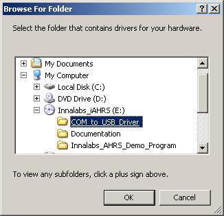
125 Fig.A.3 Fig.A.4 125
126 Fig.A.5 If the program finds the necessary files, it will automatically start the driver installation. If installation is completed successfully, the window in Fig.A.6 will appear on the screen. Press «Finish» to complete installation procedure for the COM-to-USB converter driver. Fig.A.6 126
127 If the necessary drivers are not installed, an error message (Fig.A.7) will appear. In this case, click «Back» and set the correct path to the driver files in the window in Fig.A.3. Once the converter driver is installed, you will need to know the number of the additional COM-port set by the system and configure parameters of this port for correct operation of the INS. To do this, press the «Device Manager» button in the «System Properties» window, in the «Hardware» page. In the opened «Device Manager» window (Fig.A.8) the additionally set -port will be marked as «USB serial port (COMN)». Number N in the port name will be assigned by the computer. Next, open the Properties window of this port «USB serial port (COMN) Properties» (Fig.A.9) and press the «Advanced» button. In the opened «Advanced Settings for COMN» window set the parameters: Latency Timer (msec) to 1; Minimum Read Timeout (msec) to 100; Minimum Write Timeout (msec) to 100; as it is shown in Fig.A.10, and click. Fig.A.7 127
. Twice click on this item to set its properties. The window «USB Serial Controller Properties» will be opened where go to «Advanced» tab and check «Load VCP» box (see Fig.A.12). 128")
128 Fig.A.8 In the case of problems in COM-to-USB driver operation please make one more adjustment of the driver. In the «Device Manager» window (see Fig.A.9) go to the «Universal Serial Bus controllers» section, item «USB Serial Controller» (see Fig.A.11). Twice click on this item to set its properties. The window «USB Serial Controller Properties» will be opened where go to «Advanced» tab and check «Load VCP» box (see Fig.A.12). 128

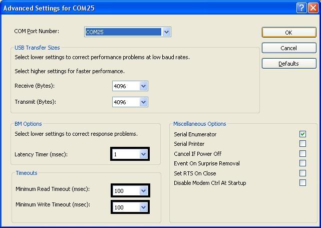
129 Fig.A.9 Fig.A

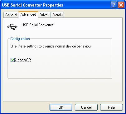
130 Fig.A.11 Fig.A
 The Inertial Labs TM INS with RS-422 interface can be connected to PC USB port using Serial-to-USB MOXA 1130")
131 APPENDIX B. Installation of the MOXA Serial-to-USB converter drivers (for INS with RS-422 interface) The Inertial Labs TM INS with RS-422 interface can be connected to PC USB port using Serial-to-USB MOXA 1130 converter, which is supplied with the INS unit by the Inertial Labs. In this case it is necessary to install appropriate driver which can be downloaded from the official MOXA site. Make sure that driver completely suits your operating system. Sequence of the MOXA 1130 converter driver installation is as follows: Click twice on icon of downloaded driver window shown on the Fig.B.1 will appear. Fig.B.1 131
132 Click «Next» button and window shown on the Fig.B.2 will appear. In the address box put the exact location where the drivers have been installed to. Fig.B.2 Click «Next» to continue installation. Then window shown on the Fig.B.3 will appear. In the address box put location and name of the program s shortcuts and click «Next» button. Window Fig.B.4. will appear where you can check the correctness of settings. If data are correct click «Install» button. In the other case click «Back» button to rewiew and change any settings. If installation completed successfully window shown on the Fig.B.5 will appear. Click «Finish» button to close installation window. 132

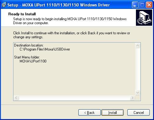
133 Fig.B.3 Fig.B.4 133
 select device «Uport 1130» in the «Multiport serial adapters» group.")
134 Fig.B.5 The next step is configuration of the installed driver. To do this, press the «Device Manager» button in the «System Properties» window, in the «Hardware» page. In the opened «Device Manager» window (see Fig.B.6) select device «Uport 1130» in the «Multiport serial adapters» group. Double click on this device to show its properties where go to the «Ports Configuration» tab (see Fig.B.7). Please check that there is set RS-422 interface as Fig.B.7 shows. If other interface is set then click on the «Port Setting» button, and in opened window Fig.B.8 select just RS-422 interface. Click «OK» button to accept configuration. 134

135 Fig.B.6 135

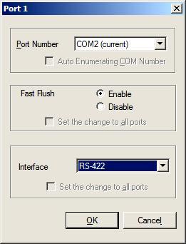
136 Fig.B.7 Fig.B.8 136
» list. There additional -port is appeared, «MOXA USB serial port (COMN)» (see Fig.B.9).")
137 Once the converter driver is installed and configured, you will need to know the number of the additional COM-port set by the system and configure parameters of this port for correct operation of the INS. To do this, go again to the «Device Manager» window Fig.B.6 and look the «Ports (COM & LPT)» list. There additional -port is appeared, «MOXA USB serial port (COMN)» (see Fig.B.9). Number N in the port name is the necessary port number assigned by the computer. Fig.B.9 137
138 APPENDIX C. Description of data files INS The Inertial Labs INS Demo software creates data files if Write button is pressed after INS start. These are two binary files with the same name and extensions.prm and.bin, where.prm file contains the INS parameters, and.bin file contains the INS outputs. Select «Report of experiment» item from the Convert menu of the INS Demo or press F8 or click button to convert these binary data to text file (see section 9 for more details). Structure of binary and text files is described below. Note that text file is more convenient for analysis. C.1. Structure of binary file If user has possibility to work with binary file directly, below is description of the binary.bin file. This file structure copies structure of the INS output data that is described in the Inertial Labs INS Interface Control Document (ICD). The first 50 bytes of the *.bin file are results of the INS initial alignment, see Table C.1. Table C.1. Structure of the first 50 bytes of *.bin file (block of initial alignment data) Byte Parameter Format Length Note 0-11 Gyros bias float 3*4 3 numbers in ADC codes Average acceleration float 3*4 3 numbers in ADC codes Average magn. field float 3*4 3 numbers in ADC codes Initial Heading float 4 degrees Initial Roll float 4 degrees Initial Pitch float 4 degrees USW word 2 0 successful initial alignment; 0 unsuccessful Notes: 1. USW is Unit Status Word (see Appendix D. The Unit Status Word definition, for details). 2. In the Table C.1 and in all next there is denoted: word = unsigned 2 byte integer; sword = signed 2 byte integer. 3. The low byte is the first. 138
139 All the next data in the *.bin file are blocks of the INS output data written at INS operation with set data rate. Each data block has structure according to the chosen output format INS OPVT, INS QPVT, INS OPVT2A, INS OPVT2AW, INS OPVT2Ahr, INS Full Output Data, INS Sensors Data and INS Minimal Data, INS NMEA, INS Sensors NMEA, TSS1. Structure of data block is described in Table C.2, Table C.5, Table C.6, Table C.7, Table C.8, Table C.9, Table C.10 and Table C.16 for each output data format. Table C.2. The INS message payload at the INS OPVT (Orientation, Position, Velocity, Time) data format Byte number Parameter Heading Pitch Length Note 2 byte word 2 byte sword Roll 2 byte sword Orientation angles, deg* GyroX, AccX, GyroY, AccY, GyroZ AccZ 3 2 byte sword Angular rates, deg/s *KG 3 2 byte sword Accelerations g*ka MagX, MagY, MagZ 3 2 byte sword Magnetic fields, nt/10 Table C.2 (continued) USW Vinp Temper 2 byte word 2 byte word Supply voltage, VDC* byte sword Temper ature, ºC*10 Byte number Parameter Length Note Byte number Parameter Latitude Longitude 4 byte integer deg *1.0e7 4 byte integer deg *1.0e7 Altitude or Heave 4 byte integer East speed 4 byte integer North speed 4 byte integer Vertical speed 4 byte integer m*100 m/s*100 m/s*100 m/s*100 Table C.2 (continued) Latitude GNSS Longitude GNSS Altitude GNSS Horizont al speed Track over ground Vertical speed 139
140 Length 4 byte integer 4 byte integer 4 byte integer 4 byte integer INS 2 byte word 4 byte integer Note deg *1.0e7 deg *1.0e7 m*100 m/s*100 deg*100 m/s*100 Byte number Table C.2 (continued) Parameter ms_gps GNSS_i nfo1 GNSS_ info2 Length 4 byte 1 byte 1 byte 1 byte 2 byte New #solnsvs Latency P_bar H_bar GPS 2 byte 4 byte word integer 1 byte Note ms s*1000 Pa/2 m*100 Notes: 1. Values of KG, KA are scale factors depending on gyro and accelerometer range: Gyro range, deg/sec 250 or or KG Accelerometer range, g KA Angular rates, linear accelerations and magnetic fields are in the carrier object axes (X is lateral axis, Y is longitudinal axis, Z is vertical axis). The INS orientation relative to the carrier object axes is set by alignment angles (see Appendix E. Variants of the Inertial Labs TM INS mounting relative to the object axes). 3. USW is unit status word (see Appendix D for details). 4. Vinp is input voltage of the INS. 5. Temper is averaged temperature in 3 gyros. 6. ms_gps are milliseconds from the beginning of the GPS reference week; 7. GNSS_info1, GNSS_info2 contain information about GNSS data (see Table C.3, Table C.4); 8. #SolnSVs is number of satellites used in navigation solution; 9. V_latency is latency in the velocity time tag in milliseconds; 10. Choice of altitude or heave and appropriate rate for output is supported in INS-D units and depends on switch Vertical position in the IMU tab of the «Devices Options» window (see section 10.3 for details). 11. P_bar, H_bar pressure and barometric height. 12. New_GPS is indicator of new update of GPS data; 13. The low byte is transmitted by first. Table C.3. GNSS_info1 information about GNSS data Bit Value and Description 0 3 Position type: 0 Single point position; 140
141 1 DGPS (pseudorange differential solution); 2 Solution calculated using corrections from SBAS; 3 PPP solution; 4 RTK (other) solution; 5 RTK (narrow-int) solution; 6 Other. 4 7 Pseudorange iono correction: 0 unknown or default Klobuchar model; 1 Klobuchar Broadcast; 2 SBAS Broadcast; 3 Multi-frequency Computed; 4 DGPS (pseudorange differential correction); 5 NovAtel Blended Iono Value. Table C.4. GNSS_info2 information about GNSS data Bit Value and Description 0 1 Solution status: 0 GNSS solution is computed; 1 insufficient observations; 2 not yet converged from cold start; 3 other reason of absent solution. 2 3 GPS reference time status: 0 time validity is unknown; 1 time is coarse set and is being steered; 2 position is lost and the range bias cannot be calculated; 3 time is fine set and is being steered. 4 1 GPS GNSS signal is used 5 1 GLONASS GNSS signal is used 6 1 Galileo GNSS signal is used 7 1 BeidDou GNSS signal is used Table C.5. The INS message payload at the INS QPVT (Quaternion of orientation, Position, Velocity, Time) data format Byte number Parameter Length Note Lk0, Lk1, Lk2, Lk3 4 2 byte sword Quaternion of orientation *10000 GyroX, GyroY, GyroZ 3 2 byte sword Angular rates, deg/s *KG AccX, AccY, AccZ 3 2 byte sword Accelerations g*ka MagX, MagY, MagZ 3 2 byte sword Magnetic fields, nt/10 USW Vinp Temper 2 byte word 2 byte word Supply voltage, VDC* byte sword Temper ature, ºC*10 141
142 Table C.5 (continued) Byte number Parameter Length Note Latitude Longitude 4 byte integer deg *1.0e7 4 byte integer deg *1.0e7 Altitude or Heave 4 byte integer East speed 4 byte integer North speed 4 byte integer Vertical speed 4 byte integer m*100 m/s*100 m/s*100 m/s*100 Table C.5 (continued) Byte number Parameter Length Latitude GNSS 4 byte integer Longitude GNSS 4 byte integer Altitude GNSS 4 byte integer Horizont al speed 4 byte integer Track over ground 2 byte word Vertical speed 4 byte integer Note deg *1.0e7 deg *1.0e7 m*100 m/s*100 deg*100 m/s*100 Byte number Table C.5 (continued) Parameter ms_gps GNSS_i nfo1 GNSS info2 #SolnSVs Length 4 byte 1 byte 1 byte 1 byte 2 byte Latency P_bar H_bar 2 byte word Note ms s*1000 Pa/2 m*100 Notes: New GPS 4 byte integer 1 byte 1. The INS QPVT data format is implemented in INS firmware since version See detailed description for correct relationship between orientation angles and quaternion in the INS ICD, rev.1.7 or higher, APPENDIX D. Forms of the Inertial Labs TM INS orientation presentation. 3. Values of KG, KA are scale factors depending on gyro and accelerometer range: Gyro range, deg/sec 250 or or KG Accelerometer range, g KA Angular rates, linear accelerations and magnetic fields are in the carrier object axes (X 142
143 is lateral axis, Y is longitudinal axis, Z is vertical axis). The INS orientation relative to the carrier object axes is set by alignment angles (see Appendix E. Variants of the Inertial Labs TM INS mounting relative to the object axes). 5. USW is unit status word (see Appendix D for details). 6. Vinp is input voltage of the INS. 7. Temper is averaged temperature in 3 gyros. 8. ms_gps are milliseconds from the beginning of the GPS reference week; 9. GNSS_info1, GNSS_info2 contain information about GNSS data (see Table C.3, Table C.4); 10. #SolnSVs is number of satellites used in navigation solution; 11. V_latency is latency in the velocity time tag in milliseconds; 12. Choice of altitude or heave and appropriate rate for output is supported in INS-D units and depends on switch Vertical position in the IMU tab of the «Devices Options» window (see section 10.3 for details). 13. P_bar, H_bar pressure and barometric height. 14. New_GPS is indicator of new update of GPS data; 15. The low byte is transmitted by first. Table C.6. The INS message payload at the INS OPVT2A (Orientation, Position, Velocity, Time, Dual-antenna receiver data) format Byte number Parameter Heading Pitch Length Note 2 byte word 2 byte sword Roll 2 byte sword Orientation angles, deg*100 GyroX, GyroY, GyroZ 3 2 byte sword Angular rates, deg/s *KG AccX, AccY, AccZ 3 2 byte sword Accelerations g*ka MagX, MagY, MagZ 3 2 byte sword Magnetic fields, nt/10 USW 2 byte word Vinp Temper 2 byte word Supply voltage, VDC* byte sword Temper ature, ºC*10 Table C.6 (continued) Byte number Parameter Length Note Latitude Longitude 4 byte integer deg *1.0e7 4 byte integer deg *1.0e7 Altitude or Heave 4 byte integer East speed 4 byte integer North speed 4 byte integer Vertical speed 4 byte integer m*100 m/s*100 m/s*100 m/s*
144 Byte number Parameter Length Table C.6 (continued) Latitude GNSS 4 byte integer Longitude GNSS 4 byte integer Altitude GNSS 4 byte integer Horizont al speed 4 byte integer Track over ground 2 byte word Vertical speed 4 byte integer Note deg *1.0e7 deg *1.0e7 m*100 m/s*100 deg*100 m/s*100 Byte number Table C.6 (continued) Parameter ms_gps GNSS_ Angles GNSS_ Heading #solnsvs V_latency position info1 info2 GNSS type Length 4 byte 1 byte 1 byte 1 byte 2 byte 1 byte 2 byte Note ms s*1000 Byte number Table C.6 (continued) Heading STD Pitch STD Parameter P_bar H_bar GNSS GNSS 2 byte 2 byte 2 byte Length word word word Note STD, deg*100 Pa/2 m*100 Notes: New GPS 4 byte integer 1 byte Pitch GNSS 2 byte word sword Orientation angles, deg* Values of KG, KA are scale factors depending on gyro and accelerometer range: Gyro range, deg/sec 250 or or KG Accelerometer range, g KA Angular rates, linear accelerations and magnetic fields are in the carrier object axes (X is lateral axis, Y is longitudinal axis, Z is vertical axis). The INS orientation relative to the 144
145 carrier object axes is set by alignment angles (see Appendix E. Variants of the Inertial Labs TM INS mounting relative to the object axes). 3. USW is unit status word (see Appendix D for details). 4. Vinp is input voltage of the INS. 5. Temper is averaged temperature in 3 gyros. 6. ms_gps are milliseconds from the beginning of the GPS reference week; 7. GNSS_info1, GNSS_info2 contain information about GNSS data (see Table C.3, Table C.4); 8. #SolnSVs is number of satellites used in navigation solution; 9. V_latency is latency in the velocity time tag in milliseconds; 10. Angles position type is GNSS position type at orientation calculation (see Table C.12); 11. Choice of altitude or heave and appropriate rate for output is supported in INS-D units and depends on switch Vertical position in the IMU tab of the «Devices Options» window (see section 10.3 for details). 12. P_bar, H_bar pressure and barometric height. 13. New_GPS is indicator of new update of GPS data; 14. The low byte is transmitted by first. Table C.7. The INS message payload at the INS OPVT2AW (Orientation, Position, Velocity, Time, Dual-antenna receiver data, GPS Week) format Byte number Parameter Heading Pitch Length Note 2 byte word 2 byte sword Roll 2 byte sword Orientation angles, deg*100 GyroX, GyroY, GyroZ 3 2 byte sword Angular rates, deg/s *KG AccX, AccY, AccZ 3 2 byte sword Accelerations g*ka MagX, MagY, MagZ 3 2 byte sword Magnetic fields, nt/10 Table C.7 (continued) USW 2 byte word Vinp Temper 2 byte word Supply voltage, VDC* byte sword Temper ature, ºC*10 Byte number Parameter Length Note Latitude Longitude 4 byte integer deg *1.0e7 4 byte integer deg *1.0e7 Altitude or Heave 4 byte integer East speed 4 byte integer North speed 4 byte integer Vertical speed 4 byte integer m*100 m/s*100 m/s*100 m/s*
146 Byte number Parameter Length Table C.7 (continued) Latitude GNSS 4 byte integer Longitude GNSS 4 byte integer Altitude GNSS 4 byte integer Horizont al speed 4 byte integer Track over ground 2 byte word Vertical speed 4 byte integer Note deg *1.0e7 deg *1.0e7 m*100 m/s*100 deg*100 m/s*100 Byte number Table C.7 (continued) Parameter ms_gps GPS week GNSS_ info1 GNSS_ info2 #solnsvs V_latency Angles position type Length 4 byte 2 byte word 1 byte 1 byte 1 byte 2 byte 1 byte Note ms s*1000 Byte number Table C.7 (continued) Parameter Heading Pitch Heading STD Pitch STD GNSS GNSS GNSS GNSS P_bar H_bar Length 2 byte 2 byte 2 byte 2 byte 2 byte 4 byte word sword word word word integer Note Orientation angles, deg*100 STD, deg*100 Pa/2 m*100 Notes: New GPS 1 byte 1. Values of KG, KA are scale factors depending on gyro and accelerometer range: Gyro range, deg/sec 250 or or KG Accelerometer range, g KA Angular rates, linear accelerations and magnetic fields are in the carrier object axes (X is lateral axis, Y is longitudinal axis, Z is vertical axis). The INS orientation relative to the carrier object axes is set by alignment angles (see Appendix E. Variants of the Inertial Labs TM INS mounting relative to the object axes). 146
147 3. USW is unit status word (see Appendix D for details). 4. Vinp is input voltage of the INS. 5. Temper is averaged temperature in 3 gyros. 6. ms_gps are milliseconds from the beginning of the GPS reference week; 7. GNSS_info1, GNSS_info2 contain information about GNSS data (see Table C.3, Table C.4); 8. #SolnSVs is number of satellites used in navigation solution; 9. V_latency is latency in the velocity time tag in milliseconds; 10. Angles position type is GNSS position type at orientation calculation (see Table C.12); 11. Choice of altitude or heave and appropriate rate for output is supported in INS-D units and depends on switch Vertical position in the IMU tab of the «Devices Options» window (see section 10.3 for details). 12. P_bar, H_bar pressure and barometric height. 13. New_GPS is indicator of new update of GPS data; 14. The low byte is transmitted by first. Table C.8. The INS message payload at the INS OPVT2Ahr (Orientation, Position, Velocity, Time, Dual-antenna receiver data, with high resolution) data format Byte number Parameter Heading Pitch Length Note 2 byte word 2 byte sword Roll 2 byte sword Orientation angles, deg*100 GyroX, GyroY, GyroZ 3 4 byte integer Angular rates, deg/s *1.0e5 AccX, AccY, AccZ 3 4 byte integer Accelerations, g*1.0e6 MagX, MagY, MagZ 3 2 byte sword Magnetic fields, nt/10 USW 2 byte word Vinp Temper 2 byte word Supply voltage, VDC* byte sword Temper ature, ºC*10 Byte number Table C.8 (continued) Altitude or East Vertical Parameter Latitude Longitude North speed Heave speed speed 8 byte 8 byte 4 byte 4 byte 4 byte 4 byte Length integer integer integer integer integer integer Note deg*1.0e9 deg*1.0e9 m*1000 m/s*100 m/s*100 m/s*
148 Byte number Parameter Length Table C.8 (continued) Latitude GNSS 8 byte integer Longitude GNSS 8 byte integer Altitude GNSS 4 byte integer Horizont al speed 4 byte integer Track over ground 2 byte word Vertical speed 4 byte integer Note deg*1.0e9 deg*1.0e9 m*1000 m/s*100 deg*100 m/s*100 Byte number Table C.8 (continued) Parameter ms_gps GNSS_ Angles GNSS_ Heading #solnsvs V_latency position info1 info2 GNSS type Length 4 byte 1 byte 1 byte 1 byte 2 byte 1 byte 2 byte Note ms s*1000 Byte number Table C.8 (continued) Heading STD Pitch STD Parameter GNSS GNSS P_bar H_bar Length 2 byte 2 byte 2 byte 4 byte word word word integer Note STD, deg*100 Pa/2 m*100 Notes: New GPS 1 byte Pitch GNSS 2 byte word sword Orientation angles, deg* Angular rates, linear accelerations and magnetic fields are in the carrier object axes (X is lateral axis, Y is longitudinal axis, Z is vertical axis). The INS orientation relative to the carrier object axes is set by alignment angles (see Appendix E. Variants of the Inertial Labs TM INS mounting relative to the object axes). 2. USW is unit status word (see Appendix D for details). 3. Vinp is input voltage of the INS. 4. Temper is averaged temperature in 3 gyros. 5. ms_gps are milliseconds from the beginning of the GPS reference week; 6. GNSS_info1, GNSS_info2 contain information about GNSS data (see Table C.3, Table C.4); 148
149 7. #SolnSVs is number of satellites used in navigation solution; 8. V_latency is latency in the velocity time tag in milliseconds; 9. Angles position type is GNSS position type at orientation calculation (see Table C.12); 10. Choice of altitude or heave and appropriate rate for is supported in INS-D units and depends on switch Vertical position in the IMU tab of the «Devices Options» window (see section 10.3 for details). 11. P_bar, H_bar pressure and barometric height. 12. New_GPS is indicator of new update of GPS data; 13. The low byte is transmitted by first. Byte number Table C.9. The message payload at the INS Full Output Data format Parameter Heading Pitch Roll Length Note Byte number 2 byte word 2 byte sword Orientation angles, deg*100 2 byte sword Ugyro, Uacc, Umag 9 2 byte sword Raw sensor data (gyros, accelerometers, magnetometers) 2 byte sword Table C.9 (continued) Mdec USW Vdd Utermo 2 byte sword deg* Parameter Latitude Longitude Length Note Byte number 4 byte integer deg *1.0e7 4 byte integer deg *1.0e7 Altitude or Heave 4 byte integer East speed 4 byte integer North speed 4 byte integer Vertical speed 4 byte integer m*100 m/s*100 m/s*100 m/s*100 Table C.9 (continued) Parameter Latitude Longitude GNSS GNSS Length 4 byte 4 byte integer integer Note deg deg *1.0e7 *1.0e7 Altitude GNSS 4 byte integer Horizontal speed 4 byte integer Track over ground 2 byte word Vertical speed 4 byte integer m*100 m/s*100 deg*100 m/s*100 2 byte word Reserved 2 byte word Combined voltage 2 byte sword Temper ature in each sensor 149
150 Byte number Table C.9 (continued) GNSS _info2 #SolnSVs V_latency UP UT New GPS Parameter ms_gps GNSS_ info1 4 byte Length integer 1 byte 1 byte 1 byte 2 byte 2 byte word Note ms s*1000 Notes 2 byte word 1 byte 1. Mdec is magnetic declination (see section 1.3 for details), since INS firmware version USW is unit status word (see Appendix D for details). 3. The following data are recorded in the field «Vdd» sequentially: - the INS input voltage, Vinp, VDC*100; - stabilized voltage supplied to the INS sensors, Vdd, VDC*1000; 4. In the «Utermo» field ADC codes are recorded sequentially from 7 temperature sensors inside gyros, accelerometers and magnetometers. 5. ms_gps are milliseconds from the beginning of the GPS reference week; 6. GNSS_info1, GNSS_info2 contain information about GNSS data (see Table C.3, Table C.4); 7. #SolnSVs is number of satellites used in navigation solution; 8. V_latency is latency in the velocity time tag in milliseconds; 9. Choice of altitude or heave and appropriate rate for output is supported in INS-D units and depends on switch Vertical position in the IMU tab of the «Devices Options» window (see section 10.3 for details). 10. UP and UT are raw data from the pressure sensor pressure and temperature. 11. New_GPS is indicator of new update of GPS data; 12. The low byte is transmitted by first. Table C.10. The message payload at the INS Sensors Data format Byte number Parameter Length Note Heading (AHRS) 2 byte word Pitch (AHRS) 2 byte sword Orientation angles, deg*100 Roll (AHRS) 2 byte sword Ugyro, Uacc, Umag 9 2 byte sword Raw sensor data (gyros, accelerometers, magnetometers) 2 byte sword 2 byte sword USW Vdd Utermo 2 byte word Reserved Reserved 2 byte word Combined voltage 2 byte sword Temper ature in each sensor 150
151 Byte number Table C.10 (continued) Parameter Latitude Longitude GNSS GNSS Length 4 byte 4 byte integer integer Note deg deg *1.0e7 *1.0e7 Byte number Altitude GNSS 4 byte integer Latitude Longitude STD STD 2 byte 2 byte word word Altitude STD 2 byte word Horizont Track over Vertical al speed ground speed 4 byte 2 byte 4 byte integer word integer m*100 m*1000 m*1000 m*1000 m/s*100 deg*100 m/s*100 Table C. 10 (continued) Parameter ms_gps TS_gps sol_stat pos_type #SVs #SolnSVs #SolnL1SVs #SolnMultiSVs Length 4 byte 1 byte 1 byte 1 byte 1 byte 1 byte 1 byte 1 byte Note ms Byte number Parameter ext_sol_ stat Table C. 10 (continued) Galileo and BeiDou Length 1 byte 1 byte 1 byte 2 byte Note s*1000 Notes GPS and GLONASS V_latency UP UT New GPS 2 byte word 2 byte word Reserv 1 byte 1 byte 1. USW is unit status word (see Appendix D for details). 2. The following data are recorded in the field «Vdd» sequentially: - the INS input voltage, Vinp, VDC*100; - stabilized voltage supplied to the INS sensors, Vdd, VDC*1000; 3. In the «Utermo» field ADC codes are recorded sequentially from 7 temperature sensors inside gyros, accelerometers and magnetometers. 4. ms_gps are milliseconds from the beginning of the GPS reference week; 5. TS_gps is time status which indicates the quality of the GPS reference time (see Table C.3); 6. sol_stat is GNSS solution status (see Table C.11); 7. pos_type is GNSS position type (see Table C.12); 8. #SVs is number of satellites tracked; 9. #SolnSVs is number of satellites used in navigation solution; 10. #SolnL1SVs is number of satellites with L1/E1/B1 signals used in solution; 11. #SolnMultiSVs is number of satellites with multi-frequency signals used in solution; 12. ext_sol_stat is GNSS extended solution status (see Table C.12); 151
152 13. GPS and GLONASS is GPS and GLONASS signal-used mask (see Table C.14); 14. Galileo and BeiDou is Galileo and BeiDou signal-used mask (see Table C.15); 15. V_latency is latency in the velocity time tag in milliseconds; 16. Choice of altitude or heave and appropriate rate for output is supported in INS-D units and depends on switch Vertical position in the IMU tab of the «Devices Options» window (see section 10.3 for details). 17. UP and UT are raw data from the pressure sensor pressure and temperature. 18. New_GPS is indicator of new update of GPS data; 19. The low byte is transmitted by first. Table C.11. sol_stat GNSS solution status Value Description 0 Solution computed 1 Insufficient observations 2 No convergence 3 Singularity at parameters matrix 4 Covariance trace exceeds maximum (trace > 1000 m) 5 Test distance exceeded (maximum of 3 rejections if distance >10 km) 6 Not yet converged from cold start 7 Height or velocity limits exceeded (in accordance with export licensing restrictions) 8 Variance exceeds limits 9 Residuals are too large 13 Large residuals make position unreliable 18 When a FIX POSITION command is entered, the receiver computes its own position and determines if the fixed position is valid a 19 The fixed position, entered using the FIX POSITION command, is not valid 20 Position type is unauthorized - HP or XP on a receiver not authorized Table C.12. pos_type GNSS position or velocity type Value Description 0 No solution 8 Velocity computed using instantaneous Doppler 16 Single point position 17 Pseudorange differential solution 18 Solution calculated using corrections from an WAAS 19 Propagated by a Kalman filter without new observations 20 OmniSTAR VBS position (1) 32 Floating L1 ambiguity solution 33 Floating ionospheric-free ambiguity solution 34 Floating narrow-lane ambiguity solution 152
153 48 Integer L1 ambiguity solution 50 Integer narrow-lane ambiguity solution 64 OmniSTAR HP position (1) 65 OmniSTAR XP or G2 position (1) 68 Converging PPP solution (2) 69 PPP solution (2) Notes (1) A subscription for OmniSTAR or use of a DGPS service is required. It is not realized in the Inertial Labs TM INS firmware yet. (2) PPP solution requires access to a suitable correction stream, delivered either through L-Band or the internet. For L-Band delivered TerraStar or Veripos service, appropriate receiver software model is required, along with a subscription to the desired service. It is not realized in the Inertial Labs TM INS firmware yet. Table C.13. ext_sol_stat GNSS extended solution status Bit Mask Description 0 0x01 If an RTK solution: NovAtel CORRECT solution has been verified If a PDP solution: solution is GLIDE Otherwise: Reserved 1-3 0x0E Pseudorange Iono Correction 0 = Unknown or default Klobuchar model 1 = Klobuchar Broadcast 2 = SBAS Broadcast 3 = Multi-frequency Computed 4 = PSRDiff Correction 5 = NovAtel Blended Iono Value 4 0x10 Reserved 5 0x20 0 = No antenna warning 1 = Antenna information is missing 6-7 0xC0 Reserved Table C.14. GPS and GLONASS signal-used mask Bit Mask Description 0 0x01 GPS L1 used in solution 1 0x02 GPS L2 used in solution 2 0x04 GPS L5 used in solution 3 0x08 Reserved 4 0x10 GLONASS L1 used in solution 5 0x20 GLONASS L2 used in solution 6-7 0x40-0x80 Reserved 153
154 Table C.15. Galileo and BeiDou signal-used mask Bit Mask Description 0 0x01 Galileo E1 used in solution 1-3 0x02-0x08 Reserved 4 0x10 BeiDou B1 used in solution 5 0x20 BeiDou B2 used in solution 6-7 0x40-0x80 Reserved INS Byte number Table C.16. The message payload at the INS Minimal Data format Parameter Heading Pitch Length Note Byte number Parameter Length Note Notes: 2 byte word 2 byte sword Orientation angles, deg*100 Roll USW Vinp Temper Latitude Longitude 2 byte 2 byte sword word 2 byte word Supply voltage, VDC* byte sword Temper ature, ºC*10 Table C.16 (continued) East speed North speed Vertical speed 4 byte 4 byte 4 byte integer integer integer m/s*100 m/s*100 m/s*100 4 byte integer deg *1.0e7 ms_gps GNSS_i #SolnSVs nfo1 4 byte 1 byte 1 byte integer 4 byte integer deg *1.0e7 1. USW is unit status word (see Appendix D for details). 2. Vinp is input voltage of the INS. 3. Temper is averaged temperature in 3 gyros. 4. ms_gps are milliseconds from the beginning of the GPS reference week; 5. GNSS_info1 contains information about GNSS data (see Table C.3); 6. #SolnSVs is number of satellites used in navigation solution. 7. The low byte is transmitted by first. Altitude or Heave 4 byte integer m*
155 At the INS NMEA output the INS data are transmitted in the form of sentences with printable ASCII characters like the NMEA 0183 format. Each sentence starts with a "$" sign and ends with <CR><LF> (carriage return 0xD and line feed 0xA symbols). All data fields are separated by commas. The general form of the NMEA Output sentence is the next $PAPR,LLmm.mmmm,n,YYYmm.mmmm,x,AAAA.aa,B,RRRR.rr,PPP.pp, HHH.hh,ttttttttt,TTT.t,VV.v,SSSS*CC<CR><LF> where PAPR is identifier and other fields are listed below: LLmm.mmmm is unsigned latitude, where LL are degrees, mm.mmmm are minutes; n is N or S (North or South); YYYmm.mmmm is unsigned longitude, where YYY are degrees, mm.mmmm are minutes; x is E or W (East or West); AAAA.aa is altitude or heave in meters; B denotes kind of height data that is defined by switch Barometric altitude in the Pressure sensor tab of the «Devices Options» window (see section 10.2): a altitude; h heave. RRRR.rr is roll in degrees; PPP.pp is pitch in degrees; HHH.hh is heading in degrees; ttttttttt is timestamp (milliseconds from the beginning of the GPS reference week); TTT.t is temperature inside INS (averaged value for 3 gyros); VV.v is input voltage of the INS; SSSS is unit status word, USW (see Appendix D for details). It is hex written with ASCII; CC is check sum that consists of a "*" and two hex digits representing XOR of all characters between, but not including "$" and "*". The INS Sensors NMEA output data have structure close to the INS NMEA, with addition of gyros and accelerometers data. So, at the INS Sensors NMEA output the INS data are transmitted in the form of sentences with printable ASCII characters like the NMEA 0183 format. Each sentence starts with a "$" sign and ends with <CR><LF> (carriage return 0xD and line feed 0xA symbols). All data fields are separated by commas. The general form of the INS Sensors NMEA output sentence is the next 155
156 $PAPS,LLmm.mmmm,n,YYYmm.mmmm,x,AAAA.aa,B,RRRR.rr,PPP.pp, HHH.hh,GGGG.xx,GGGG.yy,GGGG.zz,AA.xxxx,AA.yyyy,AA.zzzz,ttttttttt, TTT.t,VV.v,SSSS*CC<CR><LF> where PAPS is identifier and other fields are listed below: LLmm.mmmm is unsigned latitude, where LL are degrees, mm.mmmm are minutes; n is N or S (North or South); YYYmm.mmmm is unsigned longitude, where YYY are degrees, mm.mmmm are minutes; x is E or W (East or West); AAAA.aa is altitude or heave in meters; B denotes kind of height data that is defined by switch Barometric altitude in the Pressure sensor tab of the «Devices Options» window (see section 10.2): a altitude; h heave. RRRR.rr is roll in degrees; PPP.pp is pitch in degrees; HHH.hh is heading in degrees; GGGG.xx is gyro X data in degrees/s; GGGG.yy is gyro Y data in degrees/s; GGGG.zz is gyro Z data in degrees/s; AA.xxxx is accelerpmeter X data in g; AA.yyyy is accelerpmeter Y data in g; AA.zzzz is accelerpmeter Z data in g; ttttttttt is timestamp (milliseconds from the beginning of the GPS reference week); TTT.t is temperature inside INS (averaged value for 3 gyros); VV.v is input voltage of the INS; SSSS is unit status word, USW (see Appendix D for details). It is hex written with ASCII; CC is check sum that consists of a "*" and two hex digits representing XOR of all characters between, but not including "$" and "*". At the TSS1 output the INS provides accelerations, heave, pitch, and roll message in the commonly used TSS1 message format. The TSS1 data string consists of five data fields and contains 27 printable ASCII characters. The acceleration fields contain ASCII-coded hexadecimal values. Motion measurements include ASCII-coded decimal values. The general form of the TSS1 sentence is the next: :XXAAAASMHHHHQMRRRRSMPPPP<CR><LF> 156
157 Table C.17.The INS message in TSS1 format INS Message Description component : Start character XX Horizontal acceleration (hex value), in 3.83 cm/s², with a range of zero to 9.81 m/s² AAAA Vertical acceleration (hex value - 2 s complement), in cm/s², with a range of to m/s² S Space character M Space if positive; minus if negative HHHH Heave, in centimeters, with a range of to meters Q Status flag Value Description F INS Ready Mode with valid GPS input H AHRS Ready Mode without GPS input M Space if positive; minus if negative RRRR Roll, in units of 0.01 degrees (ex: 1000 = 10 ), with a range of to S Space character M Space if positive; minus if negative PPPP Pitch, in units of 0.01 degrees (ex: 1000 = 10 ), with a range of to <CR> Carriage return <LF> Line feed 157

158 C.2. Text presentation of output data formats User can choose one of the formats to view and save INS data depending on the necessary information (see Fig.4.1). Select «Report of experiment» from the Convert menu or press F8 button to convert binary data to text file for convenience. Examples of these files are shown below. In the beginning of each file, after the text «Test report», serial number of the tested INS is specified, and next are the INS firmware version, date and time of file saving. Below are examples of the saved data in each of available data formats.. 158
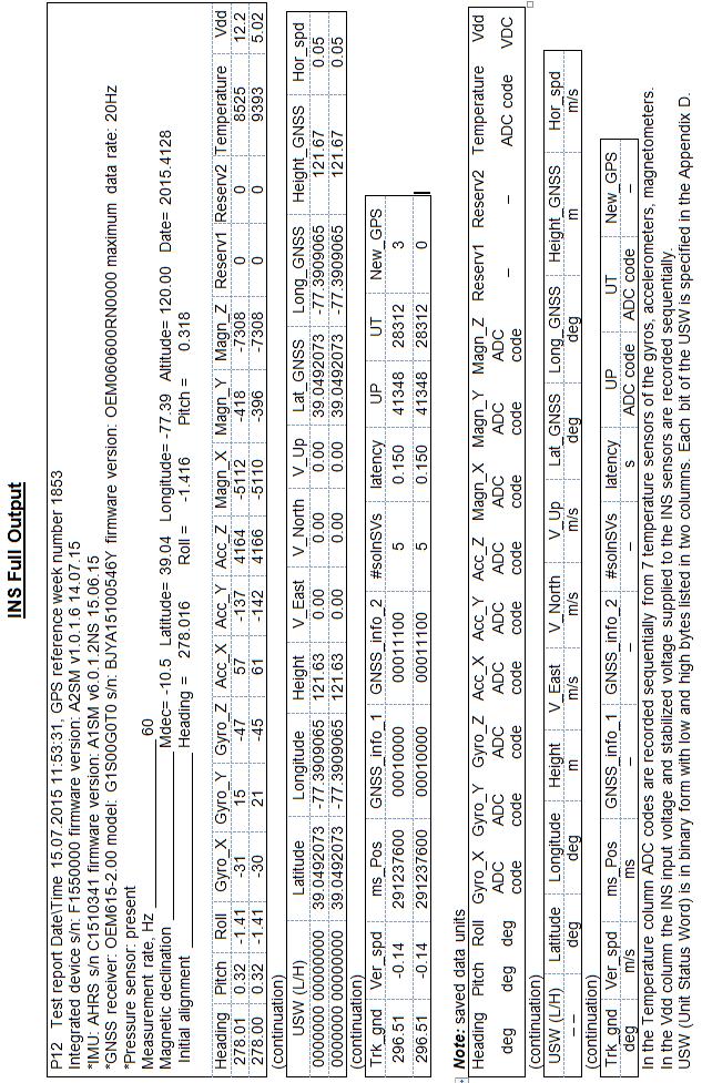
159 159
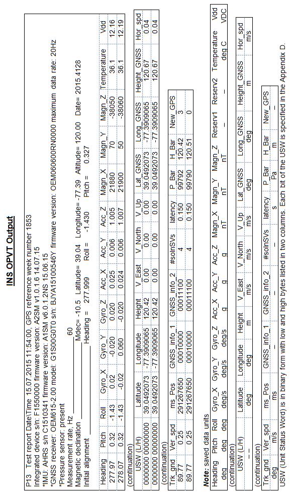
160 160
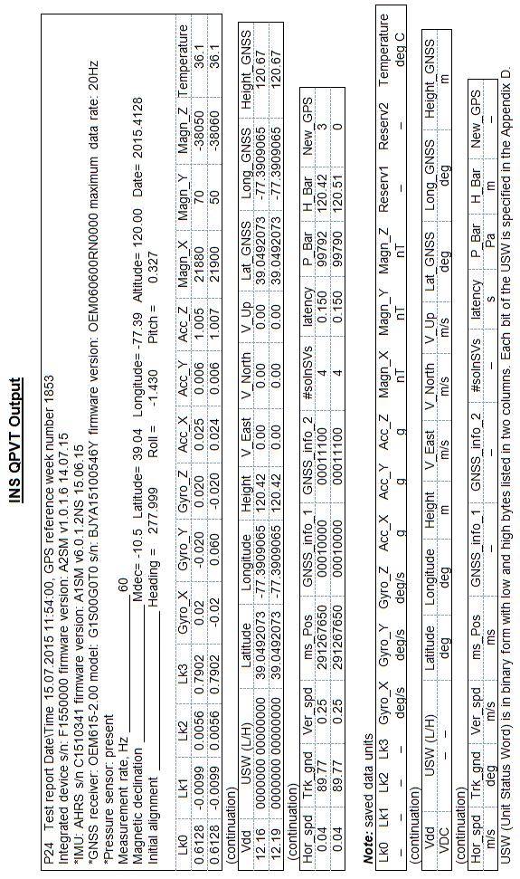
161 161
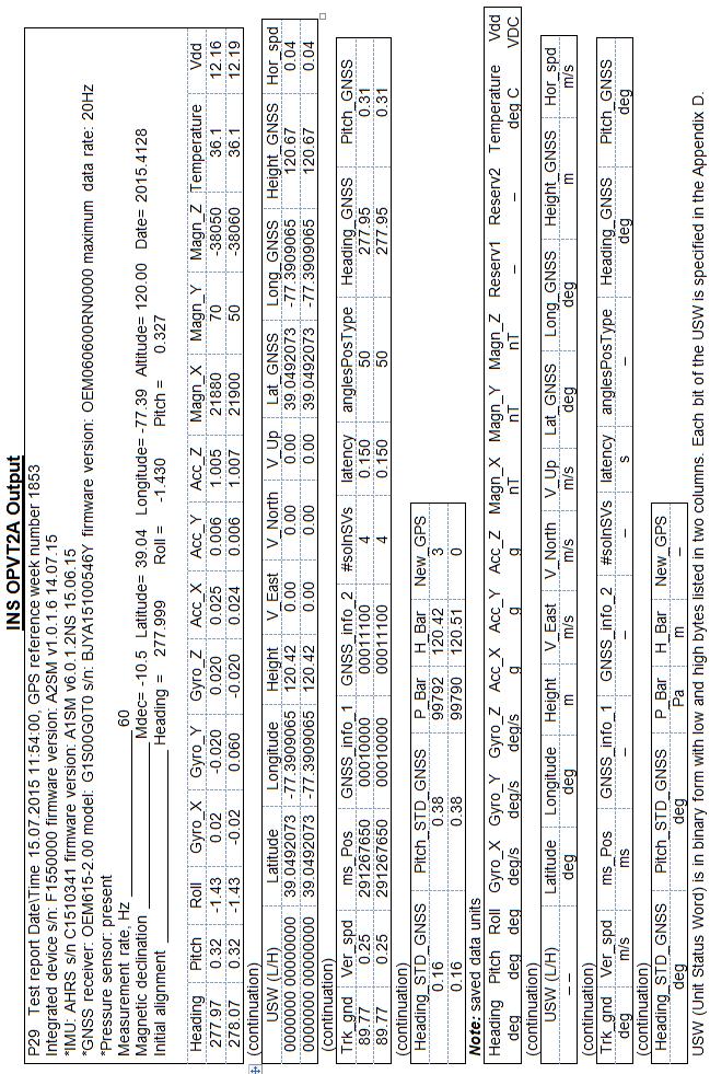
162 162
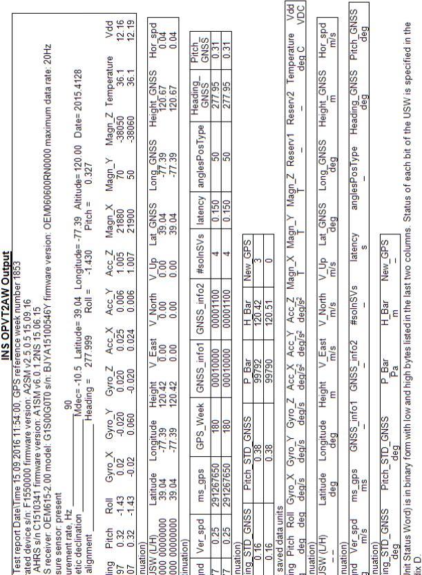
163 163
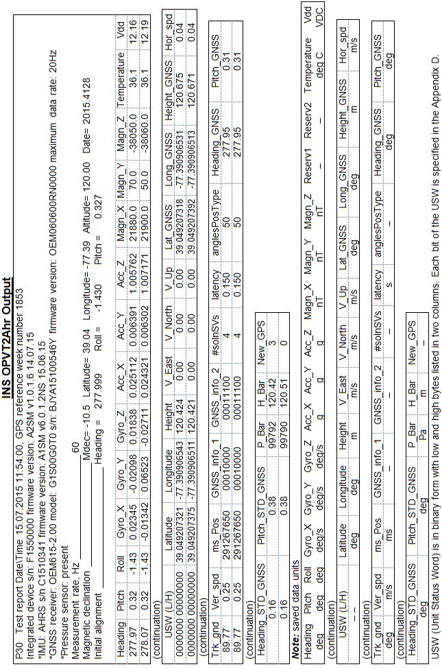
164 164
165 165
166 166
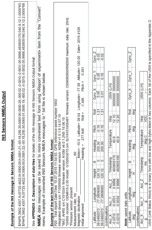
167 167
168 168
169 APPENDIX D. The Unit Status Word definition INS The Unit Status Word (USW) provides the INS state information. The low byte (bits 0-7) of USW indicates failure of the INS. If this byte is 0, the INS operates correctly, if it is not 0, see the Table D.1 for type of failure. The high byte (bits 8-15) contains a warning or is informative for the user. Status of each bit of the USW warning byte is specified in the Table D.1. Since INS Demo version from 09/02/2016 the Demo software stops the INS unit if failure of gyro, accelerometer or GNSS receiver is detected. Low (failure) byte High (warning) byte Table D.1.The INS message in TSS1 format Bit Parameter Performance 0 Successful initial alignment 0 Initial Alignment 1 Unsuccessful initial alignment due to INS moving or large change of outer magnetic field 1 INS Parameters 0 Parameters are correct 1 Parameters are incorrect 2 Gyroscope Unit 0 No failure 1 Failure is detected 0 No failure 3 Accelerometer Unit 1 Failure is detected 0 No failure 4 Magnetometer Unit 1 Failure is detected 5 Electronics 0 No failure 1 Failure is detected 6 GNSS receiver 0 No failure 1 Failure is detected 7 Reserved 0 Supply voltage is not less than minimum 8 level 1 Low supply voltage is detected 9 10 Incorrect Power Supply Angular Rate Exceeding Detect 0 Supply voltage is not higher than maximum level 1 High supply voltage is detected 0 X-angular rate is within the range 1 X-angular rate is outrange 169
170 11 0 Y-angular rate is within the range 1 Y-angular rate is outrange 12 0 Z-angular rate is within the range 1 Z-angular rate is outrange 13 Large Magnetic 0 Total magnetic field within the range Field Detect 1 Total magnetic field limit is exceeded 14 Environmental 0 Temperature is within the operating range Temperature 1 Temperature is out of the operating range 15 Reserved 170

171 APPENDIX E. Variants of the Inertial Labs TM INS mounting relative to object axes The Inertial Labs TM INS has axes orientation shown on Fig.E.1. At usual installation of the INS on carrier object the INS X, Y, Z axes should be parallel to the object lateral, longitudinal and vertical axes. X (Lateral) Z (Vertical) Heading Pitch Roll Y (Longitudinal) Fig.E.1. Coordinate system of the Inertial Labs TM INS But the Inertial Labs TM INS can be mounted on the object in any known position (up to upside-down, upright etc.) relative to the object axes. Such mounting doesn t change right calculation of the object orientation if angles of the INS mounting are correctly stored in the INS nonvolatile memory. To set these angles select item «Device option» from the «Options» menu. In opened window Fig.4.2 angles of the INS mounting are in the Alignment angles section. The INS alignment angles are set in the next order (like azimuth, pitch and roll setting): 171
172 first alignment angle sets position of the INS longitudinal axis Y relative to longitudinal axes of the object measured in the horizontal plane of the object. Clockwise rotation is positive; second alignment angle is equal to angle of inclination of the INS longitudinal axis Y relative to the horizontal plane of the object. Positive direction is up; third alignment angle is equal to inclination angle of the INS lateral axis X measured around INS s longitudinal axis. Positive rotation is X axis moving down. All angles are set in degrees. Some examples of the Inertial Labs INS mounting relative the object are shown on Fig.E.2. To check correctness of the alignment angles please run the INS using the Inertial Labs INS Demo program. 172

; b alignment angles are 0, 0,")
; d alignment angles are 180, -90, 0")
173 y a z x b y x z d z y c z x x y Fig.E.2. Examples of the Inertial Labs TM INS mounting on the carrier object a alignment angles are 0, 0, 0 (degrees); b alignment angles are 0, 0, 180 (degrees); c alignment angles are 90, 0, 0 (degrees); d alignment angles are 180, -90, 0 (degrees). 173
Motion Reference Unit MRU-P, MRU-PD
 Motion Reference Unit MRU-P, DEMO PROGRAM DEMO User s Manual Revision 1.1 Revision history Revision Date Author Description 1.0 Oct.10, 2016 AK Released version. 1.1 Nov.10,2016 AK Since MRU PD Demo Program
Interface Control Document
 Version V1.0-20170609 For INS-T Inertial Navigation System 2017 Tersus GNSS Inc. All rights reserved. Sales & Technical Support: sales@tersus-gnss.com & support@tersus-gnss.com More details, please visit
Measurement Reference Unit MRU-P, MRU-PD
 Measurement Reference Unit Revision 1.1 1 CHANGE STATUS LOG DOCUMENT: Inertial Labs TM MRU REVISION DATE AFFECTED PARAGRAPHS REMARKS 1.0 Oct. 10, 2016 All Released version. 6.2.4 Added MRU ORVTHSS output
GPS-Aided INS Datasheet Rev. 2.6
 GPS-Aided INS 1 GPS-Aided INS The Inertial Labs Single and Dual Antenna GPS-Aided Inertial Navigation System INS is new generation of fully-integrated, combined GPS, GLONASS, GALILEO and BEIDOU navigation
GPS-Aided INS Datasheet Rev. 2.3
 GPS-Aided INS 1 The Inertial Labs Single and Dual Antenna GPS-Aided Inertial Navigation System INS is new generation of fully-integrated, combined L1 & L2 GPS, GLONASS, GALILEO and BEIDOU navigation and
GPS-Aided INS Datasheet Rev. 2.7
 1 The Inertial Labs Single and Dual Antenna GPS-Aided Inertial Navigation System INS is new generation of fully-integrated, combined GPS, GLONASS, GALILEO, QZSS and BEIDOU navigation and highperformance
GPS-Aided INS Datasheet Rev. 3.0
 1 GPS-Aided INS The Inertial Labs Single and Dual Antenna GPS-Aided Inertial Navigation System INS is new generation of fully-integrated, combined GPS, GLONASS, GALILEO, QZSS, BEIDOU and L-Band navigation
Attitude and Heading Reference Systems
 Attitude and Heading Reference Systems FY-AHRS-2000B Installation Instructions V1.0 Guilin FeiYu Electronic Technology Co., Ltd Addr: Rm. B305,Innovation Building, Information Industry Park,ChaoYang Road,Qi
Inertial Sensors. Ellipse 2 Series MINIATURE HIGH PERFORMANCE. Navigation, Motion & Heave Sensing IMU AHRS MRU INS VG
 Ellipse 2 Series MINIATURE HIGH PERFORMANCE Inertial Sensors IMU AHRS MRU INS VG ITAR Free 0.1 RMS Navigation, Motion & Heave Sensing ELLIPSE SERIES sets up new standard for miniature and cost-effective
Inertial Sensors. Ellipse Series MINIATURE HIGH PERFORMANCE. Navigation, Motion & Heave Sensing IMU AHRS MRU INS VG
 Ellipse Series MINIATURE HIGH PERFORMANCE Inertial Sensors IMU AHRS MRU INS VG ITAR Free 0.1 RMS Navigation, Motion & Heave Sensing ELLIPSE SERIES sets up new standard for miniature and cost-effective
Kongsberg Seatex AS Pirsenteret N-7462 Trondheim Norway POSITION 303 VELOCITY 900 HEADING 910 ATTITUDE 413 HEAVE 888
 WinFrog Device Group: Device Name/Model: Device Manufacturer: Device Data String(s) Output to WinFrog: WinFrog Data String(s) Output to Device: WinFrog Data Item(s) and their RAW record: GPS SEAPATH Kongsberg
Inertial Sensors. Ellipse Series MINIATURE HIGH PERFORMANCE. Navigation, Motion & Heave Sensing IMU AHRS MRU INS VG
 Ellipse Series MINIATURE HIGH PERFORMANCE Inertial Sensors IMU AHRS MRU INS VG ITAR Free 0.2 RMS Navigation, Motion & Heave Sensing ELLIPSE SERIES sets up new standard for miniature and cost-effective
SERIES VECTORNAV TACTICAL SERIES VN-110 IMU/AHRS VN-210 GNSS/INS VN-310 DUAL GNSS/INS
 TACTICAL VECTORNAV SERIES TACTICAL SERIES VN110 IMU/AHRS VN210 GNSS/INS VN310 DUAL GNSS/INS VectorNav introduces the Tactical Series, a nextgeneration, MEMS inertial navigation platform that features highperformance
FLCS V2.1. AHRS, Autopilot, Gyro Stabilized Gimbals Control, Ground Control Station
 AHRS, Autopilot, Gyro Stabilized Gimbals Control, Ground Control Station The platform provides a high performance basis for electromechanical system control. Originally designed for autonomous aerial vehicle
3DM-GX4-45 LORD DATASHEET. GPS-Aided Inertial Navigation System (GPS/INS) Product Highlights. Features and Benefits. Applications
 Product Highlights. Features and Benefits. Applications") LORD DATASHEET 3DM-GX4-45 GPS-Aided Inertial Navigation System (GPS/INS) Product Highlights High performance integd GPS receiver and MEMS sensor technology provide direct and computed PVA outputs in a
LORD DATASHEET 3DM-GX4-45 GPS-Aided Inertial Navigation System (GPS/INS) Product Highlights High performance integd GPS receiver and MEMS sensor technology provide direct and computed PVA outputs in a
Quick Start. Tersus GNSS Center. Configuration Tools for Tersus GNSS RTK Systems.
 Quick Start Tersus GNSS Center Configuration Tools for Tersus GNSS RTK Systems www.tersus-gnss.com July, 2016 1. Quick Start Guide of Tersus GNSS Center This quick start guide provides the basic information
OS3D-FG MINIATURE ATTITUDE & HEADING REFERENCE SYSTEM MINIATURE 3D ORIENTATION SENSOR OS3D-P. Datasheet Rev OS3D-FG Datasheet rev. 2.
 OS3D-FG OS3D-FG MINIATURE ATTITUDE & HEADING REFERENCE SYSTEM MINIATURE 3D ORIENTATION SENSOR OS3D-P Datasheet Rev. 2.0 1 The Inertial Labs OS3D-FG is a multi-purpose miniature 3D orientation sensor Attitude
Inertial Systems. Ekinox Series TACTICAL GRADE MEMS. Motion Sensing & Navigation IMU AHRS MRU INS VG
 Ekinox Series TACTICAL GRADE MEMS Inertial Systems IMU AHRS MRU INS VG ITAR Free 0.05 RMS Motion Sensing & Navigation AEROSPACE GROUND MARINE EKINOX SERIES R&D specialists usually compromise between high
Orientus Reference Manual
 Page of 57 Version. 5// Table of Contents Revision History... Foundation Knowledge... 5. AHRS... 5. The Sensor Co-ordinate Frame... 5. Roll, Pitch and Heading... 5.. Roll... 6.. Pitch... 6.. Heading...
ENHANCEMENTS IN UAV FLIGHT CONTROL AND SENSOR ORIENTATION
 Heinz Jürgen Przybilla Manfred Bäumker, Alexander Zurhorst ENHANCEMENTS IN UAV FLIGHT CONTROL AND SENSOR ORIENTATION Content Introduction Precise Positioning GNSS sensors and software Inertial and augmentation
Motion Reference Units
 Motion Reference Units MRU Datasheet Rev. 1.3 IP-67 sealed 5% / 5 cm Heave accuracy 0.03 m/sec Velocity accuracy 0.05 deg Pitch and Roll accuracy 0.005 m/sec2 Acceleration accuracy 0.0002 deg/sec Angular
Motion Reference Units
 Motion Reference Units MRU IP-67 sealed 5% / 5 cm Heave accuracy 0.03 m/sec Velocity accuracy 0.05 deg Pitch and Roll accuracy 0.005 m/sec 2 Acceleration accuracy 0.0002 deg/sec Angular rate accuracy NMEA
Motus Reference Manual
 Page of Version. 7//6 Table of Contents 5 Revision History... Firmware Changelog... 9 Hardware Changelog... Introduction... Foundation Knowledge... 5. GNSS... 5. INS... 5. GNSS/INS... 5. AHRS... 5.5 The
GNSS Conductor GF. User s Guide. (Document No. SE )
") GNSS Conductor GF User s Guide (Document No. ) www.furuno.com IMPORTANT NOTICE No part of this manual may be reproduced or transmitted in any form or by any means, electronic or mechanical, including photocopying
GNSS Conductor GF User s Guide (Document No. ) www.furuno.com IMPORTANT NOTICE No part of this manual may be reproduced or transmitted in any form or by any means, electronic or mechanical, including photocopying
IX Feb Operation Guide. Sequence Creation and Control Software SD011-PCR-LE. Wavy for PCR-LE. Ver. 5.5x
 IX000693 Feb. 015 Operation Guide Sequence Creation and Control Software SD011-PCR-LE Wavy for PCR-LE Ver. 5.5x About This Guide This PDF version of the operation guide is provided so that you can print
TACTICAL SERIES VECTORNAV INDUSTRIAL SERIES. Key Benefits Miniaturized surface mount & Rugged packaging. < 30 grams. Embedded Navigation Solutions
 TACTICAL SERIES VECTORNAV INDUSTRIAL SERIES VN100 IMU/AH AHRS VN200 GPS/INS VN300 DUAL GNSS/INS Key Benefits Miniaturized surface mount & Rugged packaging < 30 grams Embedded Navigation Solutions THE INDUSTRIAL
Long Range Wireless OSD 5.8G FPV Transmitter
 Long Range Wireless OSD 5.8G FPV Transmitter Built-in 10 Axis AHRS + MAVLINK + 600mW Support all flight controller and GPS 1 / 14 User's Guide Catalogue Product Instruction 3 Features 3 Specifications.4
3DM -CV5-10 LORD DATASHEET. Inertial Measurement Unit (IMU) Product Highlights. Features and Benefits. Applications. Best in Class Performance
 Product Highlights. Features and Benefits. Applications. Best in Class Performance") LORD DATASHEET 3DM -CV5-10 Inertial Measurement Unit (IMU) Product Highlights Triaxial accelerometer, gyroscope, and sensors achieve the optimal combination of measurement qualities Smallest, lightest,
LORD DATASHEET 3DM -CV5-10 Inertial Measurement Unit (IMU) Product Highlights Triaxial accelerometer, gyroscope, and sensors achieve the optimal combination of measurement qualities Smallest, lightest,
INERTIAL LABS SUBMINIATURE 3D ORIENTATION SENSOR OS3DM
 Datasheet Rev..5 INERTIAL LABS SUBMINIATURE D ORIENTATION SENSOR TM Inertial Labs, Inc Address: 9959 Catoctin Ridge Street, Paeonian Springs, VA 2029 U.S.A. Tel: + (70) 880-4222, Fax: + (70) 95-877 Website:
Blue Bamboo P25 Device Manager Guide
 Blue Bamboo P25 Device Manager Guide Version of Device Manager: 1.1.28 Document version: 2.3 Document date: 2011-09-20 Products: P25 / P25-M / P25i / P25i-M BLUE BAMBOO Headquarters Blue Bamboo Transaction
Motion & Navigation Solution
 Navsight Land & Air Solution Motion & Navigation Solution FOR SURVEYING APPLICATIONS Motion, Navigation, and Geo-referencing NAVSIGHT LAND/AIR SOLUTION is a full high performance inertial navigation solution
CODEVINTEC. Miniature and accurate IMU, AHRS, INS/GNSS Attitude and Heading Reference Systems
 45 27 39.384 N 9 07 30.145 E Miniature and accurate IMU, AHRS, INS/GNSS Attitude and Heading Reference Systems Aerospace Land/Automotive Marine Subsea Miniature inertial sensors 0.1 Ellipse Series New
SPAN Data Logging for Inertial Explorer
 APN-076 ev C SPAN Data Logging for Inertial Explorer Page 1 November 16, 2017 Overview This document provides an overview of the OEM6 and OEM7 SPAN logs used for post-processing in Inertial Explorer (IE)
How to introduce LORD Sensing s newest inertial sensors into your application
 LORD TECHNICAL NOTE Migrating from the 3DM-GX4 to the 3DM-GX5 How to introduce LORD Sensing s newest inertial sensors into your application Introduction The 3DM-GX5 is the latest generation of the very
LORD User Manual 3DM -GX5-25. Attitude and Heading Reference System (AHRS)
") LORD User Manual 3DM -GX5-25 Attitude and Heading Reference System (AHRS) MicroStrain Sensing Systems 459 Hurricane Lane Suite 102 Williston, VT 05495 United States of America Phone: 802-862-6629 www.microstrain.com
LORD User Manual 3DM -GX5-25 Attitude and Heading Reference System (AHRS) MicroStrain Sensing Systems 459 Hurricane Lane Suite 102 Williston, VT 05495 United States of America Phone: 802-862-6629 www.microstrain.com
Happy Link Software INSTRUCTION MANUAL
 Happy Link Software INSTRUCTION MANUAL 101001E-3 HAPPY Contents Regarding this software Normal Operation -------------------------------------------------------------------------------------------------
The ideal K-12 science microscope solution. User Guide. for use with the Nova5000
 The ideal K-12 science microscope solution User Guide for use with the Nova5000 NovaScope User Guide Information in this document is subject to change without notice. 2009 Fourier Systems Ltd. All rights
LORD USER MANUAL. 3DM-GQ4-45 Tactical Grade GNSS-Aided Inertial Navigation System (GNSS/INS)
") LORD USER MANUAL 3DM-GQ4-45 Tactical Grade GNSS-Aided Inertial Navigation System (GNSS/INS) MicroStrain Sensing Systems 459 Hurricane Lane Suite 102 Williston, VT 05495 United States of America Phone:
LORD USER MANUAL 3DM-GQ4-45 Tactical Grade GNSS-Aided Inertial Navigation System (GNSS/INS) MicroStrain Sensing Systems 459 Hurricane Lane Suite 102 Williston, VT 05495 United States of America Phone:
DEVICE CONFIGURATION INSTRUCTIONS
 WinFrog Device Group: Device Name/Model: Device Manufacturer: Device Data String(s) Output to WinFrog: WinFrog Data String(s) Output to Device: WinFrog Data Item(s) and their RAW record: GPS POS/MV (NMEA)
BW-IMU200 Serials. Low-cost Inertial Measurement Unit. Technical Manual
 Serials Low-cost Inertial Measurement Unit Technical Manual Introduction As a low-cost inertial measurement sensor, the BW-IMU200 measures the attitude parameters of the motion carrier (roll angle, pitch
LD2342 USWM V1.6. LD2342 V1.4 Page 1 of 18
 LD2342 USWM V1.6 LD2342 V1.4 Page 1 of 18 GENERAL WARNINGS All Class A and Class B marine Automatic Identification System (AIS) units utilize a satellite based system such as the Global Positioning Satellite
SERIES VECTORNAV INDUSTRIAL SERIES VN-100 IMU/AHRS VN-200 GPS/INS VN-300 DUAL GNSS/INS
 TACTICAL VECTORNAV SERIES INDUSTRIAL SERIES VN100 IMU/AHRS VN200 GPS/INS VN300 DUAL GNSS/INS VectorNav presents the Industrial Series, a complete line of MEMSbased, industrialgrade inertial navigation
Quick Start. Precis-BX305. Precise GNSS RTK Board.
 Quick Start Precis-BX305 Precise GNSS RTK Board www.tersus-gnss.com December, 2016 Quick Start Guide of Precis-BX305 This quick start guide provides the basic information needed to set up and use Precis-BX305
ROTATING SYSTEM T-12, T-20, T-50, T- 150 USER MANUAL
 ROTATING SYSTEM T-12, T-20, T-50, T- 150 USER MANUAL v. 1.11 released 12.02.2016 Table of contents Introduction to the Rotating System device 3 Device components 4 Technical characteristics 4 Compatibility
NovAtel SPAN and Waypoint. GNSS + INS Technology
 NovAtel SPAN and Waypoint GNSS + INS Technology SPAN Technology SPAN provides continual 3D positioning, velocity and attitude determination anywhere satellite reception may be compromised. SPAN uses NovAtel
Piksi Multi Settings. 1 Introduction. Firmware Version v1.0.11
 Firmware Version v1.0.11 1 Introduction Piksi Multi has a number of settings that can be controlled by the end user via the provided Piksi Console or through the SBP binary message protocol. This Document
LORD USER MANUAL. 3DM-RQ1-45 Ruggedized Tactical Grade GPS-Aided Inertial Navigation System (GPS/INS)
") LORD USER MANUAL 3DM-RQ1-45 Ruggedized Tactical Grade GPS-Aided Inertial Navigation System (GPS/INS) MicroStrain Sensing Systems 459 Hurricane Lane Suite 102 Williston, VT 05495 United States of America
LORD USER MANUAL 3DM-RQ1-45 Ruggedized Tactical Grade GPS-Aided Inertial Navigation System (GPS/INS) MicroStrain Sensing Systems 459 Hurricane Lane Suite 102 Williston, VT 05495 United States of America
Inertial Navigation System
 Apogee Series ULTIMATE ACCURACY MEMS Inertial Navigation System INS MRU AHRS ITAR Free 0.005 RMS Motion Sensing & Georeferencing APOGEE SERIES makes high accuracy affordable for all surveying companies.
Inertial Navigation System
 Apogee Marine Series ULTIMATE ACCURACY MEMS Inertial Navigation System INS MRU AHRS ITAR Free 0.005 RMS Navigation, Motion & Heave Sensing APOGEE SERIES makes high accuracy affordable for all surveying
ExpoM - ELF User Manual
 ExpoM - ELF User Manual Version 1.4 ExpoM - ELF User Manual Contents 1 Description... 4 2 Case and Interfaces... 4 2.1 Overview... 4 2.2 Multi-color LED... 5 3 Using ExpoM - ELF... 6 3.1 Starting a Measurement...
SPAN Technology System Characteristics and Performance
 SPAN Technology System Characteristics and Performance NovAtel Inc. ABSTRACT The addition of inertial technology to a GPS system provides multiple benefits, including the availability of attitude output
1 General Information... 2
 Release Note Topic : u-blox M8 Flash Firmware 3.01 UDR 1.00 UBX-16009439 Author : ahaz, yste, amil Date : 01 June 2016 We reserve all rights in this document and in the information contained therein. Reproduction,
CMPS09 - Tilt Compensated Compass Module
 Introduction The CMPS09 module is a tilt compensated compass. Employing a 3-axis magnetometer and a 3-axis accelerometer and a powerful 16-bit processor, the CMPS09 has been designed to remove the errors
SP-6 magnetometer. User manual. Installation and in-flight calibration
 SP-6 magnetometer User manual Installation and in-flight calibration Note: This manual is applicable for SP-6 systems that contain in-flight calibration firmware released by MGL Avionics around the 15
NovAtel s. Performance Analysis October Abstract. SPAN on OEM6. SPAN on OEM6. Enhancements
 NovAtel s SPAN on OEM6 Performance Analysis October 2012 Abstract SPAN, NovAtel s GNSS/INS solution, is now available on the OEM6 receiver platform. In addition to rapid GNSS signal reacquisition performance,
Continuous High Precision Navigation Using MEMS Inertial Sensors Aided RTK GPS for Mobile Mapping Applications
 Continuous High Precision Navigation Using MEMS Inertial Sensors Aided RTK GPS for Mobile Mapping Applications Yong Li 1, Augustine Tsai 2, Peter Mumford 1, Wei-sen Lin 2, I-chou Hong 2 1 School of Surveying
BW-VG525 Serials. High Precision CAN bus Dynamic Inclination Sensor. Technical Manual
 Serials High Precision CAN bus Dynamic Inclination Sensor Technical Manual Introduction The Dynamic Inclination Sensor is a high precision inertial measurement device that measures the attitude parameters
Tiny Flight Tracker & Viewer Manual
 Tiny Flight Tracker & Viewer Manual Version 3.xx Note: Program version number that appears in the pictures of this document may not reflect the latest available release. Tiny Flight Tracker & Viewer v3.xx
LH Series Sensor Configurator Software User Manual rev. D 1/11/2012
 LH Series Sensor Configurator Software User Manual 150307 rev. D 1/11/2012 Contents Contents LH Series Sensor Overview...3 Theory of Operation...4 Outputs...4 4-20mA Analog Output...4 RS-485 Digital Output...5
PalmGauss SC PGSC-5G. Instruction Manual
 PalmGauss SC PGSC-5G Instruction Manual PalmGauss SC PGSC 5G Instruction Manual Thank you very much for purchasing our products. Please, read this instruction manual in order to use our product in safety
Table of Contents GPS
 Table of Contents GPS 6000...1 Q: Is the GPS 6000 compatible with the RTK Relay Module?...1 What is GLIDE?...2 What is StableLocâ?...3 GPS 6000/GPS 6500/GPS 6500 Relay Mounting Bracket Explainer...4 GPS
SRT Marine Technology. LD2342 V1.4 Page 1 of 22
 LD2342 V1.4 Page 1 of 22 LD2342 V1.4 Page 2 of 22 2 LD2342 V1.4 Page 3 of 22 GENERAL WARNINGS All marine Automatic Identification System (AIS) units utilise a satellite based system such as the Global
Revision 1. March 21, ADC Operation Manual N 11 th St San Jose CA
 Revision 1 March 21, 2017 ADC Operation Manual www.mountztorque.com - 1080 N 11 th St San Jose CA 95112 408.292.2214 1 Index 1. Installation 3 1.1 Required PC specification 3 1.2 Software 3 2. Operation
4.5.1 Mirroring Gain/Offset Registers GPIO CMV Snapshot Control... 14
 Thank you for choosing the MityCAM-C8000 from Critical Link. The MityCAM-C8000 MityViewer Quick Start Guide will guide you through the software installation process and the steps to acquire your first
Embedded Navigation Solutions VN-300 User Manual
 Embedded Navigation Solutions VN-300 User Manual Firmware v0.5.0.0 Document Revision 2.23 UM005 1 Document Information Title VN-300 User Manual Subtitle Inertial Navigation Modules Document Type User Manual
NovAtel SPAN and Waypoint GNSS + INS Technology
 NovAtel SPAN and Waypoint GNSS + INS Technology SPAN Technology SPAN provides real-time positioning and attitude determination where traditional GNSS receivers have difficulties; in urban canyons or heavily
----STAR S86 GPS Receiver. User Guide. SOUTH CO., Ltd.
 ----STAR S86 GPS Receiver User Guide SOUTH CO., Ltd. www.southsurveying.com Sales@SOUTHsurveying.com 2 CONTENTS Chapter 1 Introduction... 1 STAR S86 GPS - System Summary... 1 Technical Specification...
SPAN Tightly Coupled GNSS+INS Technology Performance for Exceptional 3D, Continuous Position, Velocity & Attitude
 SPAN Tightly Coupled GNSSINS Technology Performance for Exceptional 3D, Continuous Position, Velocity & Attitude SPAN Technology NOVATEL S SPAN TECHNOLOGY PROVIDES CONTINUOUS 3D POSITIONING, VELOCITY AND
LVTX-10 Series Ultrasonic Sensor Installation and Operation Guide
 LVTX-10 Series Ultrasonic Sensor Installation and Operation Guide M-5578/0516 M-5578/0516 Section TABLE OF CONTENTS 1 Introduction... 1 2 Quick Guide on Getting Started... 2 Mounting the LVTX-10 Series
Inertial Systems. Ekinox 2 Series TACTICAL GRADE MEMS. Motion Sensing & Navigation IMU AHRS MRU INS VG
 Ekinox 2 Series TACTICAL GRADE MEMS Inertial Systems IMU AHRS MRU INS VG ITAR Free 0.02 RMS Motion Sensing & Navigation AEROSPACE GROUND MARINE EKINOX 2 SERIES R&D specialists usually compromise between
3DM-GX3-45 Theory of Operation
 Theory of Operation 8500-0016 Revision 001 3DM-GX3-45 Theory of Operation www.microstrain.com Little Sensors, Big Ideas 2012 by MicroStrain, Inc. 459 Hurricane Lane Williston, VT 05495 United States of
SPEEDBOX Technical Datasheet
 SPEEDBOX Technical Datasheet Race Technology Limited, 2008 Version 1.1 1. Introduction... 3 1.1. Product Overview... 3 1.2. Applications... 3 1.3. Standard Features... 3 2. Port / Connector details...
Spatial Reference Manual
 Page of 9 Version. //7 Table of Contents 5 6 7 9 Revision History... Firmware Changelog... Hardware Changelog... 7 Introduction... Foundation Knowledge... 9 5. GNSS... 9 5. INS... 9 5. GNSS/INS... 9 5.
Inertial Systems. Ekinox 2 Series TACTICAL GRADE MEMS. Motion Sensing & Navigation IMU AHRS MRU INS VG
 Ekinox 2 Series TACTICAL GRADE MEMS Inertial Systems IMU AHRS MRU INS VG ITAR Free 0.02 RMS Motion Sensing & Navigation AEROSPACE GROUND MARINE EKINOX 2 SERIES R&D specialists usually compromise between
Digiflight II SERIES AUTOPILOTS
 Operating Handbook For Digiflight II SERIES AUTOPILOTS TRUTRAK FLIGHT SYSTEMS 1500 S. Old Missouri Road Springdale, AR 72764 Ph. 479-751-0250 Fax 479-751-3397 Toll Free: 866-TRUTRAK 866-(878-8725) www.trutrakap.com
CMPS11 - Tilt Compensated Compass Module
 CMPS11 - Tilt Compensated Compass Module Introduction The CMPS11 is our 3rd generation tilt compensated compass. Employing a 3-axis magnetometer, a 3-axis gyro and a 3-axis accelerometer. A Kalman filter
Classical Control Based Autopilot Design Using PC/104
 Classical Control Based Autopilot Design Using PC/104 Mohammed A. Elsadig, Alneelain University, Dr. Mohammed A. Hussien, Alneelain University. Abstract Many recent papers have been written in unmanned
ATLANS-C. mobile mapping position and orientation solution
 mobile mapping position and orientation solution mobile mapping position and orientation solution THE SMALLEST ATLANS-C is a high performance all-in-one position and orientation solution for both land
AHRS400 Series User s Manual
 Models AHRS400CA- AHRS400CB- AHRS400CC- (DMU-HDX-AHRS) Revision A, March 2002 Document 7430-0004-01 Crossbow Technology, Inc., 41 E. Daggett Dr., San Jose, CA 95134 Tel: 408-965-3300, Fax: 408-324-4840
CAST Application User Guide
 CAST Application User Guide for DX900+ Electromagnetic Multilog Sensor U.S. Patent No. 7,369,458. UK 2 414 077. Patents Pending 17-630-01-rev.b 05/24/17 1 Copyright 2017 Airmar Technology Corp. All rights
Date: January 16, 2003 Page 1 of 1
 Date: January 16, 2003 Page 1 of 1 1. System Accuracy 1.1 Attitude Accuracy With GPS Active Without GPS PITCH 0.2 deg 3σ 0.3 deg/hr drift 1σ ROLL 0.2 deg 3σ 0.3 deg/hr drift 1σ YAW 0.2 deg 3σ 0.3 deg/hr
ADMA. Automotive Dynamic Motion Analyzer with 1000 Hz. ADMA Applications. State of the art: ADMA GPS/Inertial System for vehicle dynamics testing
 ADMA Automotive Dynamic Motion Analyzer with 1000 Hz State of the art: ADMA GPS/Inertial System for vehicle dynamics testing ADMA Applications The strap-down technology ensures that the ADMA is stable
X3M. Multi-Axis Absolute MEMS Inclinometer Page 1 of 13. Description. Software. Mechanical Drawing. Features
 Page 1 of 13 Description The X3M is no longer available for purchase. The X3M is an absolute inclinometer utilizing MEMS (micro electro-mechanical systems) technology to sense tilt angles over a full 360
High Performance Advanced MEMS Industrial & Tactical Grade Inertial Measurement Units
 High Performance Advanced MEMS Industrial & Tactical Grade Inertial Measurement Units ITAR-free Small size, low weight, low cost 1 deg/hr Gyro Bias in-run stability Datasheet Rev.2.0 5 μg Accelerometers
Picture Style Editor Ver Instruction Manual
 ENGLISH Picture Style File Creating Software Picture Style Editor Ver. 1.18 Instruction Manual Content of this Instruction Manual PSE stands for Picture Style Editor. In this manual, the windows used in
Picture Style Editor Ver Instruction Manual
 ENGLISH Picture Style File Creating Software Picture Style Editor Ver. 1.12 Instruction Manual Content of this Instruction Manual PSE is used for Picture Style Editor. In this manual, the windows used
A3 SUPER 3 INSTRUCTION MANUAL. For Firmware Version 1.0, Data Version 1.0 Oct 25, 2017 Revision.
 A3 SUPER 3 INSTRUCTION MANUAL For Firmware Version 1.0, Data Version 1.0 Oct 25, 2017 Revision support@hobbyeagle.com 1 CONTENTS IMPORTANT NOTES.....3 1. Introduction......4 2. Setup Procedure Overview...5
Pitlab & Zbig FPV System Version 2.60a. Pitlab&Zbig OSD. New functions and changes in v2.60. New functions and changes since version 2.
 Pitlab & Zbig FPV System Version 2.60a since version 2.50a Pitlab&Zbig OSD in v2.60a Added support for new Pitlab airspeed sensor. Sensor is connected to yellow OSD socket and is configured in similar
SimCraft Control Panel CraftCon Usage Manual
 SimCraft Control Panel CraftCon Usage Manual Published Date October 2, 2007 Revision Date October 8th, 2013 Revision Date February 1st, 2014 Revision Date May 8 th, 2017 Revision Date July 9 th, 2018 Revision
Minolta Scanner Plugin
 Minolta Scanner Plugin For a list of Minolta digitizers and Geomagic software products with which this plugin is compatible, see Release Notes for Geomagic Minolta Plugin 7.6.0.3. Copyright 2005, Raindrop
Quick Start Guide for the PULSE PROFILING APPLICATION
 Quick Start Guide for the PULSE PROFILING APPLICATION MODEL LB480A Revision: Preliminary 02/05/09 1 1. Introduction This document provides information to install and quickly start using your PowerSensor+.
LC-10 Chipless TagReader v 2.0 August 2006
 LC-10 Chipless TagReader v 2.0 August 2006 The LC-10 is a portable instrument that connects to the USB port of any computer. The LC-10 operates in the frequency range of 1-50 MHz, and is designed to detect
Integration of Inertial Measurements with GNSS -NovAtel SPAN Architecture-
 Integration of Inertial Measurements with GNSS -NovAtel SPAN Architecture- Sandy Kennedy, Jason Hamilton NovAtel Inc., Canada Edgar v. Hinueber imar GmbH, Germany ABSTRACT As a GNSS system manufacturer,
Brightness and Contrast Control Reference Guide
 innovation Series Scanners Brightness and Contrast Control Reference Guide A-61506 Part No. 9E3722 CAT No. 137 0337 Using the Brightness and Contrast Control This Reference Guide provides information and
Application Note. Communication between arduino and IMU Software capturing the data
 Application Note Communication between arduino and IMU Software capturing the data ECE 480 Team 8 Chenli Yuan Presentation Prep Date: April 8, 2013 Executive Summary In summary, this application note is
LORD USER MANUAL 3DM -GX5-15. Vertical Reference Unit (VRU)
") LORD USER MANUAL 3DM -GX5-15 Vertical Reference Unit (VRU) MicroStrain Sensing Systems 459 Hurricane Lane Suite 102 Williston, VT 05495 United States of America Phone: 802-862-6629 www.microstrain.com
LORD USER MANUAL 3DM -GX5-15 Vertical Reference Unit (VRU) MicroStrain Sensing Systems 459 Hurricane Lane Suite 102 Williston, VT 05495 United States of America Phone: 802-862-6629 www.microstrain.com
Picture Style Editor Ver Instruction Manual
 ENGLISH Picture Style File Creating Software Picture Style Editor Ver. 1.15 Instruction Manual Content of this Instruction Manual PSE stands for Picture Style Editor. indicates the selection procedure
CHAPTER1: QUICK START...3 CAMERA INSTALLATION... 3 SOFTWARE AND DRIVER INSTALLATION... 3 START TCAPTURE...4 TCAPTURE PARAMETER SETTINGS... 5 CHAPTER2:
 Image acquisition, managing and processing software TCapture Instruction Manual Key to the Instruction Manual TC is shortened name used for TCapture. Help Refer to [Help] >> [About TCapture] menu for software
Scanner Utility for Microsoft Windows Version 9.6. User's Guide
 P3PC-E892-03EN Scanner Utility for Microsoft Windows Version 9.6 User's Guide For Use with Microsoft Windows 98, Windows Me, Windows 2000 and Windows XP Introduction Thank you for purchasing the "Scanner