BW-IMU200 Serials. Low-cost Inertial Measurement Unit. Technical Manual
|
|
|
- Phillip Ward
- 5 years ago
- Views:
Transcription


1 Serials Low-cost Inertial Measurement Unit Technical Manual


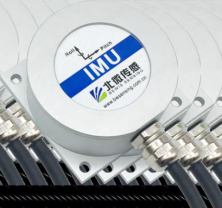
2 Introduction As a low-cost inertial measurement sensor, the BW-IMU200 measures the attitude parameters of the motion carrier (roll angle, pitch angle, angular velocity, acceleration).attitude and angular velocity deviations are estimated by a 6-state Kalman filter with appropriate gain, that is suitable for inertial attitude measurement in motion or vibration. BW-IMU200 uses highly reliable MEMS accelerometers and gyroscopes,and ensure measurement accuracy through algorithms, meanwhile, the seal design and strict process ensure that the dynamic parameters of the carrier such as the angular velocity acceleration and attitude can be accurately measured under harsh conditions. Through various compensations such as nonlinear compensation, quadrature compensation, temperature compensation and drift compensation, the error source of BW-IMU200 can be greatly eliminated, and the product accuracy level can be improved. The BW-IMU200 is equipped with digital interface that can be easily integrated into the user's system. Features Dynamic compensation and quadrature compensation Accuracy:1 Special offset tracking algorithm eliminates drift Gyro drift compensation Standard RS232/RS485/TTL output interface Operating temperature:: ,temperature compensation High-performance Kalman filter algorithm Small size: L60 W59 H29mm Applications Ship Construction machinery Platform stability Agricultural machinery Special vehicle Driverless Robot Aircraft
3 Specifications Electrical Specifications Power supply Operating current Operating temperature Store temperature 9-35V DC 40mA (DC 12V ) -40~85-55~100 Performance Specifications Accuracy 1 Pitch angle Resolution 0.01 measuring range -90 ~90 Roll angle Gyro Accelerometer Maximum output frequency Start delay Anti-vibration performance Accuracy Resolution Range Resolution Range Zero instability ARW Noise density Zero absolute error Range: X,Y,Z Resolution Bias stability 100Hz 50ms 2000g ~ /sec ±500 /sec 50 /h 1.6 / h /s/ Hz ±0.2 /sec ±2 g 1 mg ±4 mg
4 Resolution: The measured minimum change value that the sensor can detect and resolve within the measurement range. Accuracy: The error between the actual angle and the Root mean square(rms) of the measured angle of the sensor ( 16 times). Mechanical Characteristic Connector Protection level Shell material Installation Metal connector(standard cable is 1.5m)) IP67 Magnesium alloy sanding oxidation Four M4 screws Package size Product Size:L60*W59*H29(mm) Bare plate product size Product size:l44*w35*h11(mm) Note: ±1mm error for length and width dimensions, please refer to actual size 39 hole Φ 2mm


5 Installation direction The correct installation method can avoid measurement error. The following points should be made when installing the sensor: First of all, to ensure that the sensor mounting surface and the measured surface completely close, the measured surface should be as horizontal as possible, can not have the angle shown in Figure A and Figure C, the correct installation is shown in Figure B and Figure D. A B uneven surface generates the angle the measured surface the measured surface C D uneven surface generates the angle the measured surface the measured surface Secondly, the bottom cable of the sensor and the axis of the measured object shouldn't generate the angle shown in E. When installing, the bottom cable of the sensor should be kept parallel or orthogonal to the rotation axis of the measured object. This product can be installed horizontally or vertically (vertical installation requires customization). The correct installation method is shown in Figure F. Finally, the installation surface of the sensor must be fixed with the measured surface tightly and smoothly, to avoid measurement error that may be caused by the acceleration and vibration.
6 Electrical connections Electrical interfaces Cable color & function RED 1 VCC DC 9-35V BLUE 2 NC BLACK 3 GND GREEN 4 RXD (B D-) YELLOW 5 TXD (A D+) Inertial 1 measureme 7 3 nt unit Sensor DC 10-35V YELLOW: TXD RED VCC DC 9-35V YELLOW A GREEN B BLACK GND GND 6 acquisition Signal terminal 8 9 RS 485 wiring diagram Inertial measureme nt unit RED VCC YELLOW TXD GREEN RXD BLACK GND DC 9-35V GND RS 232 wiring diagram Note: The RS232 interface needs to share the product ground wire with the communication ground wire.

7 Debugging software Users can directly download serial assistant on official website (Supports-Download). You can also use more convenient and intuitive PC software. BW-IMU200 supporting serial debugging software can be connected to the inclinometer on the computer for angle display. The software debugging interface is as shown in the figure below. Using the debug software, it can conveniently display the current X-direction tilt angle, and you can also modify and set other parameters by yourself. Software usage steps Connect the serial port hardware of the inclinometer correctly and connect the power supply. Select the computer serial port and baud rate and click to connect to the serial port. Click Start and the tilt angle of the inclinometer in the X and Y directions will be displayed on the screen.
8 Protocol 1 Frame Format: (8 data bits,1 stop bit,no parity check,default baud rate 9600) (Xbyte) H Format: Hexadecimal : Fixed to 77 : Length from to (included) : Address of acquiring module, default 0x00 : Content and length variable according to : Sum of,, and. (Please pay attention that when the command or data changes, the checksum will change. ) 2 Format: 2.1 Read PITCH angle : x01 response: (3byte) 0x07 0x81 SXXX.YY Note: represents 3 byte angle value in format of compressed BCD code. S is the sign bit (0 means positive, 1 means negative), XXX is the three digit integer part, YY is the fractional part. For example, if the return value is F, the pitch angle data is , which means degrees. 2.2 Read ROLL angle : x02 0x06 response: (3byte) 0x07 0x82 SXXX.YY Note: represents 3 byte angle value in format of compressed BCD code. S is the sign bit (0 means positive, 1 means negative), XXX is the three digit integer part, YY is the fractional part.for example, if the return value is , the roll angle data is " ", which means " degrees"
9 2.3 Read PITCH, ROLL axis angle : response: (9byte) 0x0D 0x84 SXXX.YY PITCH axis: +2.01,ROLL axis: -0.51,YAW axis: D F5 ; fixed as 77 The length of the data, fixed to 0D means that in addition to 77, there are 13 bytes behind Address code, default is 00 word, fixed at 84 ROLL axis angle: The format is the same as the PITCH axis PITCH axis angle: The first digit of the first byte is the sign bit, 0 is the positive angle, and 1 is the negative angle. The second and second bytes of the first byte are integer bits of the angle, which are compressed BCD codes. The third byte is the decimal place of the angle, which is the compressed BCD code. YAW axis or reserved bit angle: the format is the same as the PITCH axis The last byte is the sum of all the previous data except the first number (). If there is a carry, the lower data is taken.
10 2.4 Set baud rate : B x0B XX response: 0x8B 0x00: success 0xFF: failure Note: 0x00 means x01 means x02 means x03 means 19200, means , default value is 0x02:9600 Each time the communication baud rate is changed successfully, the response command is sent back at the original baud rate, and then the device communication baud rate is changed immediately. Note: If high frequency output is required, set the baud rate to Modify the baud rate without sending a save command, and it will take effect immediately. 2.5 Set module address : F correct address 0x0F new address response: new address 0x8F 0x00: success 0xFF: failure Note: For example, the following command " F 0A 1E" means that the address of the product is changed from hexadecimal address 00 to 0A. 2.6 Query current address : F 23 0x00 0x1F 0x23 response: new address 0x1F new address Note: The query address command is to fix the command.
11 2.7 Set the output frequency : C x0C XX response: 0x8C 0x00: success 0xFF: failure The transmitted data field XX is the automatic output frequency option: 00 indicates the answer mode, 01 indicates 5Hz automatic output corresponding data type parameter 02 indicates 10Hz automatic output corresponding data type parameter 03 indicates 20Hz automatic output corresponding data type parameter 04 indicates 25Hz automatic output corresponding data type parameter 05 indicates 50Hz automatic output corresponding data type parameter 06 indicates 100HZ automatic output Corresponding data type parameter Note: 1. When the automatic output frequency setting is high, the baud rate needs to be set to a high baud rate. Under some data types, 100HZ cannot be output due to the baud rate limit. 2. The automatic output data type parameter is determined according to the following data type selection command. The default is the automatic output angle. 2.8 Query gravitational acceleration g : x54 response: (9byte) 0x0D 0x54 SXYYYY Note: The data field part is the value of g value of pitch, roll, Z axis (vertical horizontal plane), which consists of 1 bit sign bit + 1 bit integer bit + 4 decimal places. If the return value is "77 0D ", they are g, g, g respectively.
12 2.9 Query angular velocity : x50 response: (9byte) 0x0D 0x50 SXXXYY Note: The data field is the pitch, roll, and Z-axis (vertical horizontal) angular velocity. It consists of 1 sign bit + 3 integer bits + 2 decimal places. For example, the return value is 77 0D C0. The data field parts are: pitch axis angular velocity: /s, roll axis angular velocity: /s Z-axis angular velocity : /s 2.10 Save settings : A 0E 0x0A response: 0x8A 00:success FF: failure Note: It is not necessary to save the settings to set the baud rate. Other settings need to send the save settings Quaternion : B 0x57 response: (16byte) 0x14 0x57 SXYYYYYY Note: The data field contains 16 bytes, 4 bytes are a group, respectively quaternary q0, q1, q2, q3, which is a compressed BCD code, the format is SX YY YY YY, S is a sign bit (0 positive, 1 negative), X is a 1-bit integer bit, and YYYYYY is a 6-digit decimal place. For example, the return command F Then the quaternion data are: Where q0 is , representing q1 is , which means q2 is , which means q3 is , indicating
13 2.12 Simultaneous reading angle, accelerometer, gyroscope, quaternion : D 0x59 - response: (43byte) 0x2F 0x59 field Note: The data field contains 43 bytes, which are angle, gravitational acceleration g value, angular velocity, quaternion, compressed BCD code, four elements are the last 16 bytes, 4 bytes are a group, a total of 4 groups The rest is a group of 3 bytes, indicating the method to see the corresponding parameter return value. For example, the return value is: 77 2F C Then: the three axis angles are -0.6 degrees, degrees, 0 degrees; The g values of the three axes were g, g, and g, respectively; The three angular angular velocities are / s, / s, 0.09 / s; The four quaternions are , , , Automatic output data type selection : B 0x56 XX response: 0x56 00 Note: field XX is the corresponding output data type, which needs to be performed in automatic output mode: 0x00: When outputting automatically, the output parameter is triaxial angle data, and the output format refers to command 2.3; 0x01: When the output is automatic, the output parameter is the triaxial acceleration value, and the output format refers to the command 2.8; 0x02: When outputting automatically, the output parameter is the value of the three-axis gyroscope, and the output format refers to the command 2.9; 0x03: When outputting automatically, the output parameter is triaxial angle data (reserving other data types); : When outputting automatically, the output parameter is a quaternion value, and the output format refers to the command : When outputting automatically, the output parameters are composed of angle, acceleration, angular velocity and four elements. The output format refers to command 2.12.
14 Ordering Information Product number BW-IMU BW-IMU BW-IMU200-TTL Way of communication RS 485 RS232 TTL Package condition IP67 Package/Metal Connector IP67 Package/Metal Connector IP67 Package/Metal Connector Executive standard Enterprise Quality System Standard: ISO9001:2008 Standard (Certificate No.:10114Q16846ROS) CE certification (certificate number: ) ROHS (certificate number: SO ) GB/T 191 SJ General specifications for tiltmeters and spirit levels GBT sensor main static performance index calculation method JF Evaluation and Expression of Measurement Uncertainty GBT mechanical vibration and shock mechanical installation of accelerometer General requirements for GJB 450A-2004 equipment reliability Quality control of key parts and important parts of GJB 909A GJB 899 Reliability Qualification and Acceptance Test GJB 150-3A high temperature test GJB 150-4A low temperature test GJB 150-8A rain test GJB A dust test GJB A vibration test GJB A impact test GJB A Tilt and Swing Test GB/T A RF electromagnetic radiation immunity test GB/T A surge (hit) impulse immunity test GB/T A power frequency magnetic field immunity test GB/T A voltage dips, short interruptions and voltage changes immunity
15 Serials Low-cost inertial measurement unit Wuxi Bewis Sensing Technology LLC Address: Building 30, No. 58 Xiuxi Road, Binhu District, Wuxi City Hotline: Tel: Website:
BW-VG525 Serials. High Precision CAN bus Dynamic Inclination Sensor. Technical Manual
 Serials High Precision CAN bus Dynamic Inclination Sensor Technical Manual Introduction The Dynamic Inclination Sensor is a high precision inertial measurement device that measures the attitude parameters
IMU60 Inertial Measurement Unit
 Precision 6 DoF MEMS Inertial Measurement Unit Range: acc ±2g, gyro ±300 /s, (ODM supported) Acc Bias Instability: ±70mg, Gyro Bias Instability: 24 /h Data Update Rate: 100Hz Wide Input Power Range: 5~18VDC
SPECIFICATIONS. ACA2000 -High Accuracy Digital Type Dual-Axis Inclinometer with Full Temperature Compensation. Item No.:ACA2000
 SPECIFICATIONS Item No.:ACA2000 Description: High Accuracy Digital Type Dual-Axis Inclinometer Version:Ver.08 Production implementation standard reference Enterprise quality system standards: ISO9001:
MGA103 Single Axis MEMS Gyro with Triaxial Accelerometer
 Cost Effective Z Axis MEMS Gyro with 3 Accelerometers Heading: diverging 0.1 /hour Range: acc ±2g, gyro ±300 /s, (ODM supported) Wide Input Power Range: 6~14VDC Compact and Lightweight - 50 x 45 x 21 (mm),
MG100 Single Axis MEMS Gyro
 Cost Effective Z Axis MEMS Gyro Heading: diverging 0.1 /hour Range: gyro ±300 /s, (ODM supported) Wide Input Power Range: 6~14VDC Compact and Lightweight - 50 x 45 x 21 (mm), 70g Wide Working Temperature:
OS3D-FG MINIATURE ATTITUDE & HEADING REFERENCE SYSTEM MINIATURE 3D ORIENTATION SENSOR OS3D-P. Datasheet Rev OS3D-FG Datasheet rev. 2.
 OS3D-FG OS3D-FG MINIATURE ATTITUDE & HEADING REFERENCE SYSTEM MINIATURE 3D ORIENTATION SENSOR OS3D-P Datasheet Rev. 2.0 1 The Inertial Labs OS3D-FG is a multi-purpose miniature 3D orientation sensor Attitude
3DM-GX4-45 LORD DATASHEET. GPS-Aided Inertial Navigation System (GPS/INS) Product Highlights. Features and Benefits. Applications
 Product Highlights. Features and Benefits. Applications") LORD DATASHEET 3DM-GX4-45 GPS-Aided Inertial Navigation System (GPS/INS) Product Highlights High performance integd GPS receiver and MEMS sensor technology provide direct and computed PVA outputs in a
LORD DATASHEET 3DM-GX4-45 GPS-Aided Inertial Navigation System (GPS/INS) Product Highlights High performance integd GPS receiver and MEMS sensor technology provide direct and computed PVA outputs in a
3DM -CV5-10 LORD DATASHEET. Inertial Measurement Unit (IMU) Product Highlights. Features and Benefits. Applications. Best in Class Performance
 Product Highlights. Features and Benefits. Applications. Best in Class Performance") LORD DATASHEET 3DM -CV5-10 Inertial Measurement Unit (IMU) Product Highlights Triaxial accelerometer, gyroscope, and sensors achieve the optimal combination of measurement qualities Smallest, lightest,
LORD DATASHEET 3DM -CV5-10 Inertial Measurement Unit (IMU) Product Highlights Triaxial accelerometer, gyroscope, and sensors achieve the optimal combination of measurement qualities Smallest, lightest,
TL632D- MEMS Digital Type Gyroscope SPECIFICATIONS. Item No.:TL632D. Description:MEMS Digital Type Gyroscope. Version:Ver.05
 SPECIFICATIONS Item No.:TL632D Description:MEMS Digital Type Gyroscope Version:Ver.05 General Description TL632D is a gyroscope (angle rate sensor) based on the micro mechanical principle, a miniature
SPECIFICATIONS. DCM302B-High Accuracy 3D Electronic Compass(2D Calibration) Item No.:DCM302B
 Item No.:DCM302B") SPECIFICATIONS Item No.:DCM302B Description:High Accuracy 3D Electronic Compass(2D Calibration) Version:Ver.07 Production implementation standard reference Enterprise quality system standards: ISO9001:
SPECIFICATIONS Item No.:DCM302B Description:High Accuracy 3D Electronic Compass(2D Calibration) Version:Ver.07 Production implementation standard reference Enterprise quality system standards: ISO9001:
INERTIAL LABS SUBMINIATURE 3D ORIENTATION SENSOR OS3DM
 Datasheet Rev..5 INERTIAL LABS SUBMINIATURE D ORIENTATION SENSOR TM Inertial Labs, Inc Address: 9959 Catoctin Ridge Street, Paeonian Springs, VA 2029 U.S.A. Tel: + (70) 880-4222, Fax: + (70) 95-877 Website:
An internal gyroscope minimizes the influence of dynamic linear acceleration on slope sensor readings.
 TECHNICAL DATASHEET #TDAX06070X Triaxial Inclinometer with Gyro ±180⁰ Pitch/Roll Angle Pitch Angle Rate Acceleration SAE J1939, Analog Output or RS-232 Options 2 M12 Connectors, IP67 with Electronic Assistant
CMPS11 - Tilt Compensated Compass Module
 CMPS11 - Tilt Compensated Compass Module Introduction The CMPS11 is our 3rd generation tilt compensated compass. Employing a 3-axis magnetometer, a 3-axis gyro and a 3-axis accelerometer. A Kalman filter
Features. Description. General Specifications. VS Series Inclinometer : Dual Axis, RS232 and Analogue Output
 Features Dual axis measurement from ±5 to ±60 High resolution and accuracy Low temperature drift, with optional temperature compensation to further improve temperature performance. RS232 output interface
High Performance Advanced MEMS Industrial & Tactical Grade Inertial Measurement Units
 High Performance Advanced MEMS Industrial & Tactical Grade Inertial Measurement Units ITAR-free Small size, low weight, low cost 1 deg/hr Gyro Bias in-run stability Datasheet Rev.2.0 5 μg Accelerometers
Parameter Value Unit Notes
 Features Single axis measurement from ±5 to ±60 High resolution and accuracy. Low temperature drift, with optional temperature compensation to further improve temperature performance. RS232 and RS485 output
SOLAR-360 : 360 Inclinometer, RS232 or RS485 Output
 Features Single axis measurement, range ±180 High resolution and accuracy Low temperature drift, with optional temperature compensation to further improve temperature performance. RS232 or multi-drop RS485
CMPS09 - Tilt Compensated Compass Module
 Introduction The CMPS09 module is a tilt compensated compass. Employing a 3-axis magnetometer and a 3-axis accelerometer and a powerful 16-bit processor, the CMPS09 has been designed to remove the errors
Picture 1 PC & USB Connection
 USB Ethernet HART Profi-bus DeviceNet EtherCAT CANopen CAN RS Zigbee Analog Switch Vibration-wire PWM SSI CDMA GPRS Wi-Fi USB Inclinometer Features - Reference with USB2.0 protocol - P2P and compatible
P/N: AX06080X. TECHNICAL DATASHEET #TDAX06080X Triaxial Inclinometer SAE J1939 or CANopen 2 M12 Connector(s), IP67 with Electronic Assistant
, IP67 with Electronic Assistant") TECHNICAL DATASHEET #TDAX06080X Triaxial Inclinometer SAE J1939 or CANopen 2 M12 Connector(s), IP67 with Electronic Assistant P/N: AX06080X Features: Reliable, real-time, accurate and stable slope angle
TECHNICAL DATASHEET #TDAX06080X Triaxial Inclinometer SAE J1939 or CANopen 2 M12 Connector(s), IP67 with Electronic Assistant P/N: AX06080X Features: Reliable, real-time, accurate and stable slope angle
SOLAR-2 : Dual Axis Inclinometer, RS232 or RS485 Output
 Features Dual axis measurement, range from ±5 to ±45 High resolution and accuracy Low temperature drift, with optional temperature compensation to further improve temperature performance. RS232 or multi-drop
Attitude and Heading Reference Systems
 Attitude and Heading Reference Systems FY-AHRS-2000B Installation Instructions V1.0 Guilin FeiYu Electronic Technology Co., Ltd Addr: Rm. B305,Innovation Building, Information Industry Park,ChaoYang Road,Qi
FLCS V2.1. AHRS, Autopilot, Gyro Stabilized Gimbals Control, Ground Control Station
 AHRS, Autopilot, Gyro Stabilized Gimbals Control, Ground Control Station The platform provides a high performance basis for electromechanical system control. Originally designed for autonomous aerial vehicle
Date: January 16, 2003 Page 1 of 1
 Date: January 16, 2003 Page 1 of 1 1. System Accuracy 1.1 Attitude Accuracy With GPS Active Without GPS PITCH 0.2 deg 3σ 0.3 deg/hr drift 1σ ROLL 0.2 deg 3σ 0.3 deg/hr drift 1σ YAW 0.2 deg 3σ 0.3 deg/hr
IMU Platform for Workshops
 IMU Platform for Workshops Lukáš Palkovič *, Jozef Rodina *, Peter Hubinský *3 * Institute of Control and Industrial Informatics Faculty of Electrical Engineering, Slovak University of Technology Ilkovičova
AHRS400 Series User s Manual
 Models AHRS400CA- AHRS400CB- AHRS400CC- (DMU-HDX-AHRS) Revision A, March 2002 Document 7430-0004-01 Crossbow Technology, Inc., 41 E. Daggett Dr., San Jose, CA 95134 Tel: 408-965-3300, Fax: 408-324-4840
ASC IMU 7.X.Y. Inertial Measurement Unit (IMU) Description.
 Description.") Inertial Measurement Unit (IMU) 6-axis MEMS mini-imu Acceleration & Angular Rotation analog output 12-pin connector with detachable cable Aluminium housing Made in Germany Features Acceleration rate: ±2g
Inertial Measurement Unit (IMU) 6-axis MEMS mini-imu Acceleration & Angular Rotation analog output 12-pin connector with detachable cable Aluminium housing Made in Germany Features Acceleration rate: ±2g
INCLINOMETER RS232 SWITCH
 Main Features - Two axis digital inclinometer - Angle measurement range of +/-5, +/-15 and +/-30, Resolution up to 0.001 - Interface: RS232, Code: ASCII, Switch Open Collector - Housing: 70 mm Programmable
ability design, selected proven components directory, finite element analysis (thermal reliability analysis,
 SST400 SST300 SST200 SST100 SST30 SST20 SSG200 SSG100 SST830 SST820 SST810 SST800 SST500 Inclinometer Features - Up to ±0.001 bias stability within 12 months - Bias drift achieve ±0.0005 / - Optimization
Installation Instructions for the Transportation Attitude Reference System (TARS Series) Ruggedized Inertial Measurement Unit (IMU)
 Ruggedized Inertial Measurement Unit (IMU)") Installation Instructions for the Transportation Attitude Reference System Ruggedized Inertial Measurement Unit (IMU) Issue B 32332897 1.0 GENERAL INFORMATION Honeywell s Transportation Attitude Reference
Installation Instructions for the Transportation Attitude Reference System Ruggedized Inertial Measurement Unit (IMU) Issue B 32332897 1.0 GENERAL INFORMATION Honeywell s Transportation Attitude Reference
H3-IMU High Performance Inertial Measurement Unit
 FUNCTIONAL DESCRIPTION The H3 IMU provides serial digital outputs of triaxial acceleration, rate of turn (gyro) and magnetic field data. Custom algorithms provide high performance, temperature compensated
Model D875 Mini Tuff Tilt Digital Tiltmeter
 The model 875 Mini Tuff Tilt Tiltmeter combines high precision and durability in a miniaturized and economical instrument package. Using MEMS technology, the 875 delivers superior measurement accuracy
GPS-Aided INS Datasheet Rev. 2.6
 GPS-Aided INS 1 GPS-Aided INS The Inertial Labs Single and Dual Antenna GPS-Aided Inertial Navigation System INS is new generation of fully-integrated, combined GPS, GLONASS, GALILEO and BEIDOU navigation
P2-AHU Manual v1.0. P2-AHU Manual. (T-Module) - 1 -
 - 1 -") P2-AHU-00-01 Manual (T-Module) - 1 - 1. Overview - MEMS sensor based AHRS(Attitude & Heading Reference) micromodule - Acceleration 3 axis(x, Y, Z), magnetometer 3 axis(x, Y, Z) data provided - Angle 3
P2-AHU-00-01 Manual (T-Module) - 1 - 1. Overview - MEMS sensor based AHRS(Attitude & Heading Reference) micromodule - Acceleration 3 axis(x, Y, Z), magnetometer 3 axis(x, Y, Z) data provided - Angle 3
Inertial Sensors. Ellipse Series MINIATURE HIGH PERFORMANCE. Navigation, Motion & Heave Sensing IMU AHRS MRU INS VG
 Ellipse Series MINIATURE HIGH PERFORMANCE Inertial Sensors IMU AHRS MRU INS VG ITAR Free 0.2 RMS Navigation, Motion & Heave Sensing ELLIPSE SERIES sets up new standard for miniature and cost-effective
Data Sheet THE SCA121T DUAL AXIS INCLINOMETER MODULES. Features. Applications
 Data Sheet THE SCA121T DUAL AXIS INCLINOMETER MODULES The SCA121T Series contain 3D-MEMS-based dual axis inclinometer modules that provide instrumentation grade performance for leveling applications in
Inertial Sensors. Ellipse 2 Series MINIATURE HIGH PERFORMANCE. Navigation, Motion & Heave Sensing IMU AHRS MRU INS VG
 Ellipse 2 Series MINIATURE HIGH PERFORMANCE Inertial Sensors IMU AHRS MRU INS VG ITAR Free 0.1 RMS Navigation, Motion & Heave Sensing ELLIPSE SERIES sets up new standard for miniature and cost-effective
GPS-Aided INS Datasheet Rev. 2.7
 1 The Inertial Labs Single and Dual Antenna GPS-Aided Inertial Navigation System INS is new generation of fully-integrated, combined GPS, GLONASS, GALILEO, QZSS and BEIDOU navigation and highperformance
Technical Manual. CruizCore R1350N Rev Copyright Microinfinity Co., Ltd.
 Technical Manual CruizCore R1350N Rev1.0 2011. 12. 01 Copyright Microinfinity Co., Ltd. http://www.minfinity.com http://www.cruizcore.com Contact Info. EMAIL: supports@cruizcore.com, TEL: +82 31 546 7408
Inertial Sensors. Ellipse Series MINIATURE HIGH PERFORMANCE. Navigation, Motion & Heave Sensing IMU AHRS MRU INS VG
 Ellipse Series MINIATURE HIGH PERFORMANCE Inertial Sensors IMU AHRS MRU INS VG ITAR Free 0.1 RMS Navigation, Motion & Heave Sensing ELLIPSE SERIES sets up new standard for miniature and cost-effective
SSI Inclinometer. Zigbee. CDMA Vibration-wire. SSI PWM Switch Analog. Features. Descriptions
 SSI Inclinometer Features - Isolated SSI synchronous serial output - Compatible RS422 - Max transfer distance 400 m - IP67 protection - EMI/ESD protection - Patent tilt measuring technical, real high accuracy
Motion Reference Units
 Motion Reference Units MRU Datasheet Rev. 1.3 IP-67 sealed 5% / 5 cm Heave accuracy 0.03 m/sec Velocity accuracy 0.05 deg Pitch and Roll accuracy 0.005 m/sec2 Acceleration accuracy 0.0002 deg/sec Angular
X3M. Multi-Axis Absolute MEMS Inclinometer Page 1 of 13. Description. Software. Mechanical Drawing. Features
 Page 1 of 13 Description The X3M is no longer available for purchase. The X3M is an absolute inclinometer utilizing MEMS (micro electro-mechanical systems) technology to sense tilt angles over a full 360
GPS-Aided INS Datasheet Rev. 2.3
 GPS-Aided INS 1 The Inertial Labs Single and Dual Antenna GPS-Aided Inertial Navigation System INS is new generation of fully-integrated, combined L1 & L2 GPS, GLONASS, GALILEO and BEIDOU navigation and
GPS-Aided INS Datasheet Rev. 3.0
 1 GPS-Aided INS The Inertial Labs Single and Dual Antenna GPS-Aided Inertial Navigation System INS is new generation of fully-integrated, combined GPS, GLONASS, GALILEO, QZSS, BEIDOU and L-Band navigation
UNSTAR 传感与控制 TEL: FAX: szss AHRS300 Series User s Manual AHRS300CA- (DMU-AHRS) Revision 1.5
 Revision 1.5") AHRS300CA- (DMU-AHRS) Revision 1.5, October 2001 Document 6001-0003 2000 Crossbow Technology, Inc. All rights reserved. Information in this document is subject to change without notice. Crossbow and SoftSensor
AHRS300CA- (DMU-AHRS) Revision 1.5, October 2001 Document 6001-0003 2000 Crossbow Technology, Inc. All rights reserved. Information in this document is subject to change without notice. Crossbow and SoftSensor
GPRS Inclinometer. Zigbee. CDMA Vibration-wire. SSI PWM Switch Analog. Features. Descriptions
 GPRS Inclinometer Features - Industry GPRS interface - Quad-Band 850/ 900/ 1800/ 1900 MHz Transmission - worldwide - Support PBCCH, CSD up to 14.4 kbps - Support single/multi-center modes - Support domain
TFmini Infrared Module Specification
 Version: A00 Document No.: SJ-GU-TFmini-01 Page 1 of 10 TFmini Infrared Module Specification www.benewake.com Version: A00 Document No.: SJ-GU-TFmini-01 Page 2 of 10 Dear users: Preface Hello! Thank you
Installation Instructions for the Transportation Attitude Reference Sensor TARS Series
 Installation Instructions for the Transportation Attitude Reference Sensor TARS Series Issue A 32332897 1.0 GENERAL INFORMATION Honeywell s Transportation Attitude Reference Sensor (TARS) Interial Measurement
TL618D- MEMS Current Type Gyroscope SPECIFICATIONS. Item No.:TL618D. Description:MEMS Current Type Gyroscope. Version:Ver.05
 SPECIFICATIONS Item No.:TL618D Description:MEMS Current Type Gyroscope Version:Ver.05 General Description TL618D is a gyroscope (angle rate sensor) based on the micro mechanical principle, a miniature
Dynamic Angle Estimation
 Dynamic Angle Estimation with Inertial MEMS Analog Devices Bob Scannell Mark Looney Agenda Sensor to angle basics Accelerometer basics Accelerometer behaviors Gyroscope basics Gyroscope behaviors Key factors
ADMA. Automotive Dynamic Motion Analyzer with 1000 Hz. ADMA Applications. State of the art: ADMA GPS/Inertial System for vehicle dynamics testing
 ADMA Automotive Dynamic Motion Analyzer with 1000 Hz State of the art: ADMA GPS/Inertial System for vehicle dynamics testing ADMA Applications The strap-down technology ensures that the ADMA is stable
Motion Reference Units
 Motion Reference Units MRU IP-67 sealed 5% / 5 cm Heave accuracy 0.03 m/sec Velocity accuracy 0.05 deg Pitch and Roll accuracy 0.005 m/sec 2 Acceleration accuracy 0.0002 deg/sec Angular rate accuracy NMEA
HG1120 INERTIAL MEASUREMENT UNIT (IMU) Installation and Interface Manual
 Installation and Interface Manual") HG1120 INERTIAL MEASUREMENT UNIT (IMU) Installation and Interface Manual HG1120 Installation and Interface Manual aerospace.honeywell.com/hg1120 2 Table of Contents 4 5 6 15 17 17 Honeywell Industrial
HG1120 INERTIAL MEASUREMENT UNIT (IMU) Installation and Interface Manual HG1120 Installation and Interface Manual aerospace.honeywell.com/hg1120 2 Table of Contents 4 5 6 15 17 17 Honeywell Industrial
SKD-600D Laser Distance Sensor
 SKD-600D Laser Distance Sensor USER MANUAL version 1.0 Getting more info & supports from http://www.top1sensor.com Thank you for your choice for SKD laser distance sensor by SANKOE.LTD Please read this
USART Digital Compass Manual
 USART Digital Compass Manual General Description HMC1022-USART is a low cost plane digital compass module. The working principle is utilizing magnetoresistive sensor sensing the Earth's magnetic field
TF02 Single-point Ranging LiDAR Product Specification
 Document No: SJ-GU-TF02-01 Version: A01 TF02 Single-point Ranging LiDAR Product Specification Benewake (Beijing) Co. Ltd. Page 1 Document No: SJ-GU-TF02-01 Version: A01 Dear users, Preface We would like
Specifications Attitude and Heading Specifications. GP9 GPS-Aided AHRS Datasheet, Revision 1.3
 Introduction The GP9 GPS-Aided AHRS combines MEMS inertial sensors and embedded GPS with an Extended Kalman Filter to produce attitude estimates that are immune to long-term angular drift and sustained
OughtToPilot. Project Report of Submission PC128 to 2008 Propeller Design Contest. Jason Edelberg
 OughtToPilot Project Report of Submission PC128 to 2008 Propeller Design Contest Jason Edelberg Table of Contents Project Number.. 3 Project Description.. 4 Schematic 5 Source Code. Attached Separately
NRA24 millimeter wave radar User manual
 NRA24 millimeter wave radar User manual (With check sum) Hunan Nanoradar Science and Technology Co., Ltd. Disclaimers Thanks to purchase this product. There is web pages about NRA24 altimeter in our official
SERIES VECTORNAV TACTICAL SERIES VN-110 IMU/AHRS VN-210 GNSS/INS VN-310 DUAL GNSS/INS
 TACTICAL VECTORNAV SERIES TACTICAL SERIES VN110 IMU/AHRS VN210 GNSS/INS VN310 DUAL GNSS/INS VectorNav introduces the Tactical Series, a nextgeneration, MEMS inertial navigation platform that features highperformance
Mercury technical manual
 v.1 Mercury technical manual September 2017 1 Mercury technical manual v.1 Mercury technical manual 1. Introduction 2. Connection details 2.1 Pin assignments 2.2 Connecting multiple units 2.3 Mercury Link
SPECIFICATIONS. AKE390B-MEMS Voltage Type Accelerometer. Item No.:AKE390B. Description:MEMS Voltage Type Accelerometer. Version:Ver.
 SPECIFICATIONS Item No.:AKE390B Description:MEMS Voltage Type Accelerometer Version:Ver.06 Production implementation standard reference Enterprise quality system standards: ISO9001: 2008 standard (certification
Communications message formats
 Communications message formats The SP-1 or SP-2 unit communicates via the airtalk compatible communications port. This port consists of a shared, single wire asynchronous link. The link operates with one
MTi 100-series The most accurate and complete MEMS AHRS and GPS/INS
 Orientation. Position. Xsens. MTi 100-series The most accurate and complete MEMS AHRS and GPS/INS The 4th generation MTi sets the new industry standard for reliable MEMS based INS s, AHRS s, VRU s and
Accelerometer user manual
 Accelerometer user manual V1.5 COPY RIGHTS ECOTRONS LLC ALL RIGHTS RESERVED Note: If you are not sure about any specific details, please contact us at info@ecotrons.com. Index Page Revision Date Note 1
If you want to use an inertial measurement system...
 If you want to use an inertial measurement system...... which technical data you should analyse and compare before making your decision by Dr.-Ing. E. v. Hinueber, imar Navigation GmbH Keywords: inertial
SPECIFICATIONS. Item No.:AKE398B. Description:MEMS Current Type Accelerometer. Version:Ver.06. AKE398B-MEMS Current Type Accelerometer
 SPECIFICATIONS Item No.:AKE398B Description:MEMS Current Type Accelerometer Version:Ver.06 Production implementation standard reference Enterprise quality system standards: ISO9001: 2008 standard (certification
Cost efficient design Operates in full sunlight Low power consumption Wide field of view Small footprint Simple serial connectivity Long Range
 Cost efficient design Operates in full sunlight Low power consumption Wide field of view Small footprint Simple serial connectivity Long Range sweep v1.0 CAUTION This device contains a component which
302 VIBROENGINEERING. JOURNAL OF VIBROENGINEERING. MARCH VOLUME 15, ISSUE 1. ISSN
 949. A distributed and low-order GPS/SINS algorithm of flight parameters estimation for unmanned vehicle Jiandong Guo, Pinqi Xia, Yanguo Song Jiandong Guo 1, Pinqi Xia 2, Yanguo Song 3 College of Aerospace
HPC Compass NMEA Version. Installation and Operation Manual
 HPC Compass NMEA Version Installation and Operation Manual NMEA HPC COMPASS 13-1 NMEA HPC COMPASS This manual is written for the NMEA HPC Compass transducer 1.1 Edition: 1.4 May 2010 13-2 NMEA HPC COMPASS
Cost efficient design Operates in full sunlight Low power consumption Wide field of view Small footprint Simple serial connectivity Long Range
 Cost efficient design Operates in full sunlight Low power consumption Wide field of view Small footprint Simple serial connectivity Long Range sweep v1.0 CAUTION This device contains a component which
3DM-GX3-45 Theory of Operation
 Theory of Operation 8500-0016 Revision 001 3DM-GX3-45 Theory of Operation www.microstrain.com Little Sensors, Big Ideas 2012 by MicroStrain, Inc. 459 Hurricane Lane Williston, VT 05495 United States of
Application Note. Communication between arduino and IMU Software capturing the data
 Application Note Communication between arduino and IMU Software capturing the data ECE 480 Team 8 Chenli Yuan Presentation Prep Date: April 8, 2013 Executive Summary In summary, this application note is
CENG 5931 HW 5 Mobile Robotics Due March 5. Sensors for Mobile Robots
 CENG 5931 HW 5 Mobile Robotics Due March 5 Sensors for Mobile Robots Dr. T. L. Harman: 281 283-3774 Office D104 For reports: Read HomeworkEssayRequirements on the web site and follow instructions which
Extended Kalman Filtering
 Extended Kalman Filtering Andre Cornman, Darren Mei Stanford EE 267, Virtual Reality, Course Report, Instructors: Gordon Wetzstein and Robert Konrad Abstract When working with virtual reality, one of the
SENLUTION Miniature Angular & Heading Reference System The World s Smallest Mini-AHRS
 SENLUTION Miniature Angular & Heading Reference System The World s Smallest Mini-AHRS MotionCore, the smallest size AHRS in the world, is an ultra-small form factor, highly accurate inertia system based
MTi 100-series The most accurate and complete MEMS AHRS and GPS/INS
 Orientation. Position. Xsens. MTi 100-series The most accurate and complete MEMS AHRS and GPS/INS The 4th generation MTi sets the new industry standard for reliable MEMS based INSs AHRSs, VRUs and IMUs.
User manual. Inclinometer with Analog-RS232-Interface IK360
 User manual Inclinometer with Analog-RS232-Interface IK360 Table of content 1 GENERAL SAFETY ADVICE... 3 2 INTRODUCTION... 4 2.1 IK360... 4 2.2 ANALOG INTERFACE... 4 2.3 IK360 ANALOG... 4 3 INSTALLATION...
USER GUIDE OCTANS III & POSITIONING NAVIGATION II. PART 2 : OCTANS III SURFACE USER GUIDE
 USER GUIDE OCTANS III NAVIGATION & POSITIONING II. PART 2 : OCTANS III SURFACE USER GUIDE TABLE OF CONTENTS II.1 OCTANS Technical description... II-5 II.1.1 Performances... II-6 II.1.1.1 Gyrocompass Technical
Migrating from the 3DM-GX3 to the 3DM-GX4
 LORD TECHNICAL NOTE Migrating from the 3DM-GX3 to the 3DM-GX4 How to introduce LORD MicroStrain s newest inertial sensors into your application Introduction The 3DM-GX4 is the latest generation of the
OBSOLETE. Digital Output, High Precision Angular Rate Sensor ADIS Data Sheet FEATURES GENERAL DESCRIPTION APPLICATIONS FUNCTIONAL BLOCK DIAGRAM
 Data Sheet Digital Output, High Precision Angular Rate Sensor FEATURES Low noise density: 0.0125 o /sec/ Hz Industry-standard serial peripheral interface (SPI) 24-bit digital resolution Dynamic range:
SPEEDBOX Technical Datasheet
 SPEEDBOX Technical Datasheet Race Technology Limited, 2008 Version 1.1 1. Introduction... 3 1.1. Product Overview... 3 1.2. Applications... 3 1.3. Standard Features... 3 2. Port / Connector details...
Orientus Reference Manual
 Page of 57 Version. 5// Table of Contents Revision History... Foundation Knowledge... 5. AHRS... 5. The Sensor Co-ordinate Frame... 5. Roll, Pitch and Heading... 5.. Roll... 6.. Pitch... 6.. Heading...
HG G B. Gyroscope. Gyro for AGV. Device Description HG G B. Innovation through Guidance. Autonomous Vehicles
 Device Description HG G-84300-B Autonomous Vehicles Gyroscope HG G-84300-B Gyro for AGV English, Revision 06 Date: 24.05.2017 Dev. by: MG/WM/Bo Author(s): RAD Innovation through Guidance www.goetting-agv.com
HG4930 INERTIAL MEASUREMENT UNIT (IMU) Performance and Environmental Information
 Performance and Environmental Information") HG493 INERTIAL MEASUREMENT UNIT () Performance and Environmental Information HG493 Performance and Environmental Information aerospace.honeywell.com/hg493 2 Table of Contents 4 4 5 5 6 7 8 9 9 9 Honeywell
HG493 INERTIAL MEASUREMENT UNIT () Performance and Environmental Information HG493 Performance and Environmental Information aerospace.honeywell.com/hg493 2 Table of Contents 4 4 5 5 6 7 8 9 9 9 Honeywell
GPS Time and Frequency Reference Receiver
 $ GPS Time and Frequency Reference Receiver Symmetricom s 58540A GPS time and frequency reference receiver features: Eight-channel, parallel tracking GPS engine C/A Code, L1 Carrier GPS T-RAIM satellite
Module 2: Lecture 4 Flight Control System
 26 Guidance of Missiles/NPTEL/2012/D.Ghose Module 2: Lecture 4 Flight Control System eywords. Roll, Pitch, Yaw, Lateral Autopilot, Roll Autopilot, Gain Scheduling 3.2 Flight Control System The flight control
Reference Diagram IDG-300. Coriolis Sense. Low-Pass Sensor. Coriolis Sense. Demodulator Y-RATE OUT YAGC R LPY C LPy ±10% EEPROM TRIM.
 FEATURES Integrated X- and Y-axis gyro on a single chip Factory trimmed full scale range of ±500 /sec Integrated low-pass filters High vibration rejection over a wide frequency range High cross-axis isolation
Instruction Manual Single and Dual Axis Inclinometer P-Series
 Instruction Manual Single and Dual Axis Inclinometer P-Series Version 1.2 Hauert 13, D-44227 Dortmund, Germany 1 of 16 fax: +49-(0)231-9740-200 Table of Contents 1 Introduction... 3 2 Notice... 3 3 History...
How to introduce LORD Sensing s newest inertial sensors into your application
 LORD TECHNICAL NOTE Migrating from the 3DM-GX4 to the 3DM-GX5 How to introduce LORD Sensing s newest inertial sensors into your application Introduction The 3DM-GX5 is the latest generation of the very
K-Band Doppler Sensor Module
 Released K-Band Doppler Sensor Module RF Frequency: 24.5 to 24.25 GHz Model No. NJR4266 series Frequency Line-up: J: 24.5 to 24.25 GHz / JAPAN F2: 24.15 to 24.25 GHz / EU F3: 24.75 to 24.175 GHz / US Antenna
±300 /sec Yaw Rate Gyro ADXRS620
 ±3 /sec Yaw Rate Gyro ADXRS62 FEATURES Complete rate gyroscope on a single chip Z-axis (yaw rate) response High vibration rejection over wide frequency 2 g powered shock survivability Ratiometric to referenced
Device manual Inclination sensor 2 axes JN /00 04/2015
 Device manual Inclination sensor 2 axes JN2300 80228165/00 04/2015 Contents 1 Preliminary note................................................. 4 1.1 Symbols used...............................................
E31-TTL-500 Datasheet V Feature E31-TTL-500
 E31-TTL-500 Datasheet V1.0.1.Introduction E31-TTL-500 1.1 Feature E31-TTL-500 E31-TTL-500 is a 500mW wireless transceiver module with narrow-band transmission, operates at 425-450.5MHz (default: 433MHz),
Inertial Systems. Ekinox Series TACTICAL GRADE MEMS. Motion Sensing & Navigation IMU AHRS MRU INS VG
 Ekinox Series TACTICAL GRADE MEMS Inertial Systems IMU AHRS MRU INS VG ITAR Free 0.05 RMS Motion Sensing & Navigation AEROSPACE GROUND MARINE EKINOX SERIES R&D specialists usually compromise between high
Integrated Dual-Axis Gyro IDG-1004
 Integrated Dual-Axis Gyro NOT RECOMMENDED FOR NEW DESIGNS. PLEASE REFER TO THE IDG-25 FOR A FUTIONALLY- UPGRADED PRODUCT APPLICATIONS GPS Navigation Devices Robotics Electronic Toys Platform Stabilization
xoem500 Hardware Integration Manual Inertial and GNSS measurement system Confidently. Accurately.
 xoem500 xf Inertial and GNSS measurement system Hardware Integration Manual Confidently. Accurately. Table of contents Introduction 5 Related documents 6 Precautions 7 Compliance testing 7 Hardware description
Revisions Revision Date By Changes A 11 Feb 2013 MHA Initial release , Xsens Technologies B.V. All rights reserved. Information in this docum
 MTi 10-series and MTi 100-series Document MT0503P, Revision 0 (DRAFT), 11 Feb 2013 Xsens Technologies B.V. Pantheon 6a P.O. Box 559 7500 AN Enschede The Netherlands phone +31 (0)88 973 67 00 fax +31 (0)88