MAXI Remote Location Kit MRLK 900 Installation and Configuration Manual
|
|
|
- Mae Hoover
- 5 years ago
- Views:
Transcription

1 MAXI Remote Location Kit MRLK 900 Installation and Configuration Manual 01/
2 Table of Contents Introduction... 3 Materials Included... 3 Setup Overview... 4 Radio Configuration Overview:... 4 FreeWaveTool Suite Installation: ) For Configuring Using Tool Suite Configuration: ) For Configuring Using Setup Terminal in FreeWave Tool Suite: ) For Configuring Using HyperTerminal: Yagi Antenna Installation: PolyPhaser Installation: Signal Loss Additional Resources: Appendix: ) Identifying COM Port ) Checking Signal Strength
3 Introduction The MAXI Remote Location Kit 900 utilizes 900 MHz Spread Spectrum radios to position a Field Interface such as a MIM 2-Wire, MIM LINK, LDI, SDI, or ICI at a remote location from the central control computer. The MRLK 900 includes two PolyPhaser surge arrestors to provide inline protection against surge events at the locations of both radios. These installation instructions assume that the user is already familiar with the installation instructions and physical layout of the MIM 2-Wire, MIM LINK, LDI, SDI, or ICI products. If further information is needed regarding these types of products, please refer to their respective manuals. Materials Included The MRLK 900 kit contains the following materials: Number Find 1 2 Description FGR2-CE, 902 to 928MHz, Frequency Hopping Spread Spectrum wireless data transceiver in a ruggedized enclosure with TNC female RF connector, DB9 female connector, accepts +6 to +30 VDC. Transformer Input: 120VAC 12W Output: 12VDC 500mA EMD 1280UX Quantity 2 2 3A RS232 Interface Cable DB9 Male to DB9 Female 2 3B RS232 Interface Cable Null Modem DB9 Female to DB9 Female 1 Not Pictured 4 (At Radio) DB9 Male to Male Gender Changer (Used with Null Modem Cable) 2 RFT-1234 N Female to TNC Male Straight Adaptor Foot Coaxial Cable with male N type connectors (0.24 diameter, 1.7dB loss) MHz 6dB 4 element Yagi directional antenna 2 6 Not Pictured Not Pictured PolyPhaser - Throughput Energy 220µJ (typical) Frequency Range: 125MHz to 1000MHz Max. Power: VHF 375W, UHFLow 125W 800MHz to 1GHz 50W 2 FGR2-CE-U Diagnostic and Programming Cable ASC0409DC REV C CCX User Manual 1 1 3


4 Setup Overview The following diagram in Figure 1 depicts a typical before and after configuration for the installation of the MRLK 900. Radio Configuration Overview: Prior to the installation of the MRLK 900, the FreeWave 900 MHz Spread Spectrum radios require configuring. All adjustments are done through the FreeWave Tool Suite. The program can be downloaded from the FreeWave website at: The configuration can also be performed using Microsoft s HyperTerminal program provided with most versions of Microsoft Windows. The FreeWave radios operate in a Master/Slave configuration for point to point use. Therefore, the radio used at the computer location must be setup as a master using the steps below, and 4


5 the other will be setup as a slave to be used at the remote interface location. As appropriate, the actions pertaining to the steps below will be highlighted accordingly to differentiate between the directions associated with a master radio configuration and those of a slave radio configuration. The FreeWave radios are not fully pre-configured from the factory. While many of the required parameters are pre-configured, the corresponding radio s serial number must be added and other settings should be verified to ensure that the radios will communicate properly. After programming the Master radio and prior to establishing a communication link with a slave or repeater, all three of the master s LEDs will be solid red (Note: Always connect an antenna before powering a radio). Even though the TX LED may appear dimmer than the other LEDs, it should be displayed at a level which is detectable from being completely off. The MRLK Radios should be configured using the following software and steps: FreeWaveTool Suite Installation: 1. Insert disc if provided and use the autorun.exe program. If software is downloaded from FreeWave Website run the FreeWave Tool Suite Web Install executable. 2. Select Install Software, and then select Tool Suite vx.x.x on the next window. If the software on your Disk is older than the below version it can be updated in the Tool Suite. 3. Continue through the Setup Wizard, this may prompt you to restart the computer. Restart prior to completing the next steps. Once restarted, complete the following installation. 5

 from the left navigation bar, and then click check updates (2b) in the top left to complete any necessary updates to the Tool Suite")
6 1) For Configuring Using Tool Suite Configuration: 1. Connect one of the radios to one of the computers COM ports using the supplied Diagnostics and Programming Cable. Use a Serial to USB adaptor if no Serial port is available. Provide power to the FreeWave radio using the supplied transformer; before powering the radio, an antenna must be connected or immediate damage to the radio may occur. 2. Open the Free Wave Tool Suite, select the Updates icon (2a) from the left navigation bar, and then click check updates (2b) in the top left to complete any necessary updates to the Tool Suite software. 2b 2a 3. After updating the software select the configuration button (3a) from the left navigation bar. 4. In the drop down menu under Com Port (4a), select the port in which the radio is connected. To determine the correct com port please review the Appendix section of this manual. 4a 3a 6
7 5. Enter Programming mode by pressing the black button on the back of the radio (5a). When the setup program is invoked, all three LEDs on the front panel of the FreeWave radio will turn green and will remain green for the entire time the radio is in setup mode. 5a 6. Select Read Radio (6a). This will download and communicate with the connected radio. 6a Verify that the serial number on the setup program screen matches the serial number on the bottom of the FreeWave radio. In addition to providing the radio s unique serial number, the setup program provides a set of choices for editing the operational parameters and viewing the performance data. Also, you should change the name of the radio to signify if it is the master radio or the slave radio, and any other unique identifiers. 7


8 7. Select the Operation Mode tab, the first line under modem mode should be set to (0) Point to Point Master when configuring the master radio and (1) Point to Point Slave when configuring the slave radio. Select the Baud Rate tab, then select the appropriate Baud rate for the application. For the MIM and MIM LINK determine the baud rate setting by looking at the baud rate jumper on the inside of the Interface door. Use the table below to determine the selected baud rate for the MIM. For most other applications including the ICI, SDI, and LDI the Baud rate should be set to Jumper Baud Rate E5 E4 9,600 E4 E3 1,200 All other settings should reflect those of the below image: 8
 should match the serial number located on the bottom side of the master radio. 9.")
 LED on each radio will turn solid")
9 8. Next select the Call Book Tab : For the master radio, the number for Entry (0) should match the serial number located on the bottom side of the slave radio. For the slave radio, the number for Entry (0) should match the serial number located on the bottom side of the master radio. 9. IMPORTANT! Select Program All (10a) to write the configuration changes to the radio when complete. 10. After configuration of both the Master and Slave radios has been successfully completed, the Carrier Detect (CD) LED on each radio will turn solid green when the radios detect each other s signal. 10a 9

, the COM port assigned to the adapter must be selected. 3.")
10 2) For Configuring Using Setup Terminal in FreeWave Tool Suite: 1. Click on Setup Terminal icon on the left navigation bar. 2. Select the Com port the Diagnostics and Programming Cable is connected to and click connect. To determine the correct com port please review the Appendix section of this manual. Note: When using a USB-to-serial adapter (not included), the COM port assigned to the adapter must be selected. 3. Select 0 to set Operation Mode. 4. Select 0 to configure radio as Master. 10


11 5. Press the ESC key to return to the main menu 6. Select 1 to set the Baud Rate 7. Select the appropriate baud rate according to the type of interface: Interface Baud Rate Selection Choice MIM, MIM LINK,TWI, TWI LINK MIM, MIM LINK,TWI, TWI LINK, SDI, LDI, ICI Press the ESC key to return to the main menu 11


12 9. Select 2 to enter the serial number to the Slave radio into the Call Book 10. Type the serial number of the Slave radio. Also enter and Repeater 1 or Repeater 2 addresses if you are using repeaters in your system. 11. Now repeat the above steps for the slave radio, enter 1 at step 4 to configure the radio as the Slave, enter the Master radio s serial number into the Slave radio s Call book in step

. Provide power to the FreeWave radio using the supplied transformer. 2.")
. 5.")
13 3) For Configuring Using HyperTerminal: Note: Not all Windows PC s have HyperTerminal pre-installed. HyperTerminal can be found online through a quick web search. 1. Connect one of the radios to the COM1 port of a computer using a standard RS232 cable (not the provided Null Cable ). Provide power to the FreeWave radio using the supplied transformer. 2. Start Microsoft s HyperTerminal program in Windows from Start Programs Accessories Communications. 3. Double-click on the HYPERTRM icon. 4. Enter a Name for the New Connection (temporary name). 5. Select Direct to Com1 from Connect Using pull-down. 13
: When the radio enters programming mode, all three LEDs on the front panel of the FreeWave radio will turn")

14 6. Select the following settings for the COM1 Properties window: Bits per second: Data bits: 8 Parity:None Stop bits: 1 Flow control: None 7. Enter programming mode by pressing the black Setup button on the back of the radio(7a): When the radio enters programming mode, all three LEDs on the front panel of the FreeWave radio will turn green and will remain green for the entire time the radio is in programming mode. 7a 8. Verify that the serial number on the setup program screen matches the serial number on the bottom of the FreeWave radio. In addition to providing the radio s unique serial number, the setup program provides a set of choices for editing the operational parameters and viewing the performance data. Set operational mode by entering 0. Serial Number Operational Mode 14

15 9. Verify that the radio displaying three solid LEDs after connecting power is configured as the master, and the other radio is configured as the slave. This can be verified by checking the second line of text in the SET MODEM MODE menu as shown below. The second line of text should show the following: For Master radio: Modem Mode is 0 For Slave radio: Modem Mode is 1 If the radios have not been pre-configured correctly for the Modem Mode, then configure each radio using the following: For Master radio: Enter 0 to select Point to Point Master. For Slave radio: Enter 1 to select Point to Point Slave. If the Modem Mode has been configured properly, then press ESC to return to the Main Menu. 15
 should match the serial number located on the bottom of the Slave radio.")
16 10. Verify that each radio has been pre-configured to communicate with the other by checking the entries in the Call Book for each radio. Enter 2 to Edit Call Book from the Main Menu. For Master radio: The Number for Entry (0) should match the serial number located on the bottom of the Slave radio. For Slave radio: The Number for Entry (0) should match the serial number located on the bottom of the Master radio. To change the Number of an entry, enter the entry number followed by the seven-digit serial number. Do not enter a - after the third digit, the formatting of the number is automatic. For example, to enter the serial number into Entry (0), enter a 0 followed by from the MODEM CALL BOOK menu. Verify that the Call Entry selection of each radio has been pre-configured to communicate with the other radio. This can be verified by checking the second line of text in the MODEM CALL BOOK menu as shown above. The second line of text should show the following: Entry to Call is 00 If the second line of text does not show the same text as above, then select C followed by a 0 to change the selection to the (0) Call Entry. Press ESC to return to the Main Menu. 16


17 11. For use with a MAXI Interface Module determine the baud rate setting for the MIM by looking at the baud rate select jumper on the inside of the door as shown below. Use the table below to determine the selected baud rate of the MIM. The baud rate setting for an SDI, LDI, or ICI will be 9,600. Jumper Baud Rate E5 E4 9,600 E4 E3 1, Enter 1 to Set Baud Rate from the Main Menu. From the Set Baud Rate Menu, enter a 6-9,600 or a 9-1,200 to match the baud rate setting determined from the previous step. This baud rate setting will be used to configure each radio. Press ESC to return to the Main Menu. Press ESC to Exit Setup. 13. After completing the setup program for one of the radios, perform steps 7-13 for the other radio, making sure that the Operation Mode selection is set to the opposite mode of the other radio. After configuring both radios, exit from the HyperTerminal program by closing the window or using the Exit selection in the File dropdown menu. 17

18 Select Yes to disconnect from the current session of HyperTerminal. Yagi Antenna Installation: Prior to the installation of the radios and the antennas, disconnect the power to the interface to prevent communication until the installation is complete. It is highly desirable to obtain a line of sight when mounting the Yagi directional antennas to increase the strength and reliability of the communication signal. Note: All connections need to be sealed to protect from the elements, this requires a vulcanizing rubberized tape. PolyPhaser Installation: A PolyPhaser surge protector must be installed at each radio location to provide in-line protection against lightning. Each of the PolyPhaser surge protectors must be grounded using a dedicated external grounding rod with a resistance of 50 Ohms or less to earth ground (not included). Note: All connections need to be sealed to protect from the elements, this requires a vulcanizing rubberized tape. Signal Loss Signal loss can become a significant problem under several circumstances. For example, increasing the cable length without increasing antenna gain will negatively affect Radio Frequency (RF) range. The same is true is multiple connectors are used to extend the cable, this will negatively affect RF range as well. Additional Resources: For any additional resources please check the Rain Brid Golf website at the following link: You can also contact your local Rain Bird Distributor, Sales Representative, or the Rain Bird GSP Group for assistance with setup, configuration, or any other questions. 18
. Locate the Ports section and expand it.")
19 Appendix: 1) Identifying COM Port COM Port Assigned to a USB-to-Serial Adapter When a USB-to-serial adapter is initally connected, Windows will assign a COM port to it. To find out what COM port has been assigned, go to Device Manager (type device in the start menu search field, then click on Device Manager). Locate the Ports section and expand it. Find the USB-to-Serial adapter. 19


20 If needed, the COM port number may be changed using the following steps: 1. Right click on the USB-to-Serial adapter device in Device manager and select properties. 2. Choose the Port Settings tab 3. Click on Advanced 4. Click the COM Port Number drop down menu and choose the desired COM port number (e.g. COM1) Click OK to confirm your choice 5. Click OK to close the Device Properties window. 6. Close Device manager 20

 For Configuring Using Setup Terminal in FreeWave Tool Suite. 3.")
21 2) Checking Signal Strength Checking radio signal strength is accomplished through use of the Setup Terminal in the FreeWave Tool Suite. To do this simple test follow the below steps: Note: Radio s should be communicating for a minimum of 20 minutes prior to measuring statistics. 1. Open FreeWave Tool Suite. 2. Connect to the radio and open the Setup Terminal using steps from Section 2) For Configuring Using Setup Terminal in FreeWave Tool Suite. 3. Select (4) to enter the Radio Statistics screen. 4. The radio statistics will be presented. Compare these to the levels provided on the next page. 21
22 Modem Statistics The below statistics are recommended by Rain Bird. If any major deviation occurs please contact Rain Bird GSP for assistance. Number of Disconnects: o 0-1 Antenna Reflected Power: o 5 o 5-30 o 30+ = Good = Acceptable = Problems with Cables/Connectors in Antenna System Average Noise Level: o <70 J units, and difference between Average Noise and Average Signal levels should be >26 J units Average Signal Level: o >26 J units difference between Average Noise and Average Signal Overall RCV Rate (%): o >75 o <15 = Robust link = Marginal to Weak Next press Enter key to display Frequency Information. See image on next page for example. 22
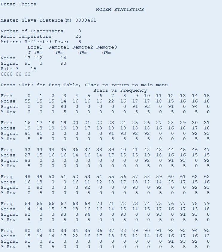
23 23
Using the FGR-115MB in Mirrored Bit Applications
 Using the FGR-115MB in Mirrored Bit Applications The FreeWave Technologies FGR-115MB Spread Spectrum transceiver is a special version of the FGR-Series product family. It provides additional features that
Using the FGR-115MB Radio with Schweitzer Engineering Labs Mirrored Bits Communications
 The FreeWave Technologies FGR-115MB Spread Spectrum transceivers is a special version of the FGR series product family which have been optimized for use with Schweitzer. In certain applications this provides
Guardian and DL3282 Modem Interface Technical Service Application Note
 Guardian and DL3282 Modem Interface Technical Service Application Note OVERVIEW The following document is designed to provide information for the implementation of the Guardian Wireless Modem/Analog Radio
CONTROL MICROSYSTEMS SCADAWave Radio Transceiver. Hardware Manual
 5908 SCADAWave Radio Transceiver Hardware Manual CONTROL MICROSYSTEMS SCADA products... for the distance 48 Steacie Drive Telephone: 613-591-1943 Kanata, Ontario Facsimile: 613-591-1022 K2K 2A9 Technical
Operations Manual for RFExtender Setup
 Operations Manual for RFExtender Setup Revised December 03, 2004 TABLE OF CONTENTS INTRODUCTION...3 SYSTEM COMPONENTS...3 TRANSCEIVER MODULE SETUP...3 SINGLE LOGGER SYSTEM SETUP...5 MULTIPLE LOGGER SYSTEM
IC System TM Design Guide v 2.3
 IC System TM Design Guide v 2.3 Updated August 2016 IC System TM Product Definitions... 3 Integrated Control Interface (ICI)... 4 Integrated Control Module (ICM)... 5 Integrated Control Surge Device (ICSD)...
The CO2 Sensor Calibration Kit
 The CO2 Sensor Kit For use with all BAPI CO 2 Sensors Instruction Manual CO 2 Kit Product Identification and Overview BAPI s CO 2 Sensor Kit is designed to calibrate and verify the operation of all BAPI
Dragon. manual version 1.7
 Dragon manual version 1.7 Contents DRAGON TOP PANEL... 2 DRAGON STARTUP... 2 DRAGON STARTUP SCREEN... 2 DRAGON INFO SCREEN... 3 DRAGON MAIN SCREEN... 3 TURNING ON A TRANSMITTER... 4 CHANGING MAIN SCREEN
FreeWave Technologies DGR-115 / 115H User Manual V3.71 Quick Start Note:
 Quick Start Your pair of FreeWave Wireless Data Transceivers are shipped from the factory preconfigured to operate in point-to-point applications. The Transceivers are preset for high speed data communications
Revision WI.232FHSS-25-FCC-R and RK-WI.232FHSS-25-FCC-R USER S MANUAL
 Revision 1.0.3 WI.232FHSS-25-FCC-R and RK-WI.232FHSS-25-FCC-R USER S MANUAL RADIOTRONIX, INC. WI.232FHSS-25-FCC-R/ RK-WI.232FHSS-25-FCC-R USER S MANUAL Radiotronix 905 Messenger Lane Moore, Oklahoma 73160
RM24100D. Introduction. 1 Features. 2.4GHz 100mW RS232 / RS485 / RS422 DSSS Radio Modem (IEEE compliant) Operating Manual English 1.
 Operating Manual English 1.") RM24100D 2.4GHz 100mW RS232 / RS485 / RS422 DSSS Radio Modem (IEEE 802.15.4 compliant) Operating Manual English 1.03 Introduction The RM24100D radio modem acts as a wireless serial cable replacement and
RM24100D 2.4GHz 100mW RS232 / RS485 / RS422 DSSS Radio Modem (IEEE 802.15.4 compliant) Operating Manual English 1.03 Introduction The RM24100D radio modem acts as a wireless serial cable replacement and
AES 7705i MultiNet Receiver System Initial Installation and Setup Guide
 AES 7705i MultiNet Receiver System Initial Installation and Setup Guide AES Corporation 285 Newbury Street. Peabody, Massachusetts 01960-1315 USA Tel: USA (978) 535-7310. Fax: USA (978) 535-7313 Copyright
Antenna and Propagation
 Antenna and Propagation This courseware product contains scholarly and technical information and is protected by copyright laws and international treaties. No part of this publication may be reproduced
ADI-100 Interrupter. Operator s Manual. 526 S. Seminole Bartlesville, OK /
 ADI-100 Interrupter Operator s Manual 526 S. Seminole Bartlesville, OK 74003 918/336-1221 www.sescocp.com ADI - 100 Interrupter FEATURES Clock Accuracy 100% during GPS lock Clock Drift 30 µsec per degree
IQ TM Spread Spectrum (SS) Radio
 Radio") IQ TM Spread Spectrum (SS) Radio Installation Guide for the IQ TM Central Control System 638174-02 Rev A (IQ SS-Radio install guide (EN)) source.indd 1 12/17/2010 11:39:14 AM Symbols NOTE: Symbol alerts
IQ TM Spread Spectrum (SS) Radio Installation Guide for the IQ TM Central Control System 638174-02 Rev A (IQ SS-Radio install guide (EN)) source.indd 1 12/17/2010 11:39:14 AM Symbols NOTE: Symbol alerts
BANTAM INSTRUMENTS SOFTWARE USER S MANUAL MIL-STD-461E PRE-COMPLIANCE MEASUREMENT SYSTEM MODEL EMC-461. Model EMC-461 Software User s Manual
 BANTAM INSTRUMENTS MIL-STD-461E PRE-COMPLIANCE MEASUREMENT SYSTEM MODEL EMC-461 SOFTWARE USER S MANUAL MIL-STD-461E PRE-COMPLIANCE MEASUREMENT SYSTEM MODEL EMC-461 Software User s Manual BANTAM INSTRUMENTS
FreeWave Spread Spectrum Wireless Data Transceiver. User Manual
 FreeWave Spread Spectrum Wireless Data Transceiver User Manual FreeWave Technologies, Inc. 1880 South Flatiron Court Boulder, CO 80301 USA (303) 444-3862 (303) 786-9948 Fax www.freewave.com FreeWave Spread
Preliminary. DN-900 Series. 900 MHz Wireless Serial Modems
 Preliminary - 900 MHz RS-232C, RS-485/RS-232C and USB Serial Modems - Optional 128-Bit AES Encryption - Point-to-point, Point-to-multipoint, Peer-to-peer and Tree-routing Network Capabilities - Frequency
Getting Started with TrangoLink
 Getting Started with TrangoLink Overview: TrangoLink allows you to configure and monitor your EAGLE PLUS, FALCON, or PTZ-900 transmitters and receivers. On the EAGLE PLUS and FALCON transmitters, you can
Wireless Howto. Rev 9
 Wireless Howto Rev 9 The Overdrive System can use radio modems to communicate between the Control Computer ( CC ) and the Embedded Computer ( EC ). The modem manufacturer is Cirronet (GA, USA). The model
APX Mobile and Portable Automated Test and Alignment
 APX Mobile and Portable Automated Test and Alignment Software Updates First things first! Be sure to check that you are running the latest software versions for the 8800SX and its applications. Visit the
PC Tune PC Tune Test Procedures for 5100 Series Portable Radios
 PC Tune PC Tune Test Procedures for 5100 Series Portable Radios Part Number 002-9998-6513014 August 2008 Copyright 2006, 2007, 2008 by EFJohnson Technologies The EFJohnson Technologies logo, PC Configure,
Preliminary. RF Data Transmission Rates 38.4, 115.2, 200 and 500 kbps
 Preliminary - 2.4 GHz RS-232C, RS-485/RS-232C and USB Serial Modems - Optional 128-Bit AES Encryption - Point-to-point, Point-to-multipoint, Peer-to-peer and Tree-routing Network Capabilities - Frequency
CL4490 HARDWARE INTEGRATION GUIDE VERSION 1.0. FCC Notice.
 CL4490 HARDWARE INTEGRATION GUIDE VERSION 1.0 wireless.support@lairdtech.com FCC Notice WARNING: This device complies with Part 15 of the FCC Rules. Operation is subject to the following two conditions:
WBT900. User s Manual. 900 MHz Wireless BACnet MSTP Radio. Page 1
 WBT900 User s Manual 900 MHz Wireless BACnet MSTP Radio www.aic-wireless.com Page 1 Thank you for your purchase of the WBT900, Wireless BACnet MSTP Transceiver. With appropriate placement and antenna selection,
SMR5000F. User Manual. Smart Radio Data Repeater. Web Site: P.N.: Book 092
 SMR5000F Smart Radio Data Repeater User Manual ISRAEL Office: Email: info@kpsystems.com PO Box 42, Tefen Industrial Park, Tefen 24959 Tel: 972-4-987-3066 / Fax: 972-4-987-3692 USA Office: KP ELECTRONICS,
RM24100A. Introduction. 1 Features. 2.4GHz 100mW RS232 / RS485 / RS422 DSSS Radio Modem (IEEE compliant) Operating Manual English 1.
 Operating Manual English 1.") RM24100A 2.4GHz 100mW RS232 / RS485 / RS422 DSSS Radio Modem (IEEE 802.15.4 compliant) Operating Manual English 1.03 Introduction The RM24100A radio modem acts as a wireless serial cable replacement and
RM24100A 2.4GHz 100mW RS232 / RS485 / RS422 DSSS Radio Modem (IEEE 802.15.4 compliant) Operating Manual English 1.03 Introduction The RM24100A radio modem acts as a wireless serial cable replacement and
Product catalog. May Where any application finds its wireless solution L E X Y C O M T E C H N O L O G I E S, I N C
 Product catalog May 2010 T E L I O N 1 3 0 0 T R A N S C E I V E R M I L I T A R Y U S E Fully Digital Software Defined Radio Transceiver Capable of supporting virtually any type of waveform Provides ARDS-compliant
Multilin DGT. Distributed Generation Trip Control Fast & Wireless Trip of Distributed Generators. Control. Advanced Communications
 Multilin DGT Distributed Generation Trip Control Fast & Wireless Trip of Distributed Generators The desire for green power and rapid developments in renewable energy sources are driving the growth of distributed
SPECIAL SPECIFICATION 6574 Low Power Wireless Modem
 2004 Specifications CSJ 1068-04-126, etc. SPECIAL SPECIFICATION 6574 Low Power Wireless Modem 1. Description. This work shall consist of furnishing and supplying a Low Power Wireless Modem at the locations
Antennas and Wireless Accessories
 Antennas and Wireless Accessories Description Page No. Antennas and Wireless Accessories see pages 1430 1434 www.crouse-hinds.com US: 1-866-764-5454 CAN: 1-800-265-0502 Copyright 2010 Cooper Crouse-Hinds
TESS I. Wireless Control System. Installation and User Manual. RPM Control Company Toll Free 1
 TESS I Wireless Control System Installation and User Manual RPM Control Company 1-866-519-9817 Toll Free www.rpmcontrol.com 1 Table of Contents: 1. Introduction 1.1 Service and support 1.2 Product returns
RF Wireless Serial Device Server
 RF-SDS RF Wireless Serial Device Server The RF-SDS subassembly is a radio transceiver acting as a Serial Device Server, which externally connects a remote serial RF transceiver to an Ethernet network (TCP/IP).
Frequency Hopping Spread Spectrum Ethernet Radio Modem
 User Guide Industrial Data Communications SRM7210E Frequency Hopping Spread Spectrum Ethernet Radio Modem It is essential that all instructions contained in the User Guide are followed precisely to ensure
AcuMesh Wireless RS485 Network. User's Manual SOLUTION
 AcuMesh Wireless RS485 Network User's Manual AN SOLUTION ACUMESH - WIRELESS METERING SYSTEM COPYRIGHT 2015 V1.2 This manual may not be altered or reproduced in whole or in part by any means without the
Faculty of Electrical & Electronics Engineering BEE4233 Antenna and Propagation. LAB 1: Introduction to Antenna Measurement
 Faculty of Electrical & Electronics Engineering BEE4233 Antenna and Propagation LAB 1: Introduction to Antenna Measurement Mapping CO, PO, Domain, KI : CO2,PO3,P5,CTPS5 CO1: Characterize the fundamentals
PlantLinc 5000 USER GUIDE PLR5000. Industrial Frequency Hopping Spread Spectrum Radio Modem INDUSTRIAL DATA COMMUNICATIONS
 USER GUIDE INDUSTRIAL DATA COMMUNICATIONS PlantLinc 5000 PLR5000 Industrial Frequency Hopping Spread Spectrum Radio Modem It is essential that all instructions contained in the User Guide are followed
EVDP610 IXDP610 Digital PWM Controller IC Evaluation Board
 IXDP610 Digital PWM Controller IC Evaluation Board General Description The IXDP610 Digital Pulse Width Modulator (DPWM) is a programmable CMOS LSI device, which accepts digital pulse width data from a
Technical Note #15. Radio Frequency Modems. GE ED&C Home Search ED&C GE ED&C Power Management Home GE ED&C PMCS Home
 1 of 5 GE ED&C Home Search ED&C GE ED&C Power Management Home GE ED&C PMCS Home GE Power Management Control System Description Software Hardware Operation Product Support Operator Interfaces F A Q s App
EMWIN User Training. For Colorado Front Range. September, 2007
 EMWIN User Training For Colorado Front Range September, 2007 Agenda 1 p.m. Getting Started SOME ASSEMBLY REQUIRED Antenna Radio equipment RealEMWIN Software installation 2:30 p.m. Basic features of RealEMWIN
Installation & Quick Start Guide AIT2000 Class B AIS Transponder
 Installation & Quick Start Guide AIT2000 Class B AIS Transponder QUICK START AIT2000 - VR1.01 1. Introduction Congratulations on the purchase of your AIT2000 Class B AIS Transponder. It is recommended
MIDLAND PROGRAMING G14
 MIDLAND PROGRAMING G14 1. PROGRAMMING CAPABILITY Welcome to the MIDLAND Programming software! It s a programming software specifically designed for G14 and must be used in conjunction with the dedicated
WLM. Serial (RS-485) MHz. Wireless Link Module. Serial (RS-485) MHz. December A. Wireless Link ModuleWLM
 MHz. Wireless Link Module. Serial (RS-485) MHz. December A. Wireless Link ModuleWLM") December 2003 288-787-02 A Wireless Link ModuleWLM Serial (RS-485) 902-928MHz WLM Wireless Link Module Serial (RS-485) 902-928MHz 2 The Interface Solution Experts Table of Contents Page Introduction...4
December 2003 288-787-02 A Wireless Link ModuleWLM Serial (RS-485) 902-928MHz WLM Wireless Link Module Serial (RS-485) 902-928MHz 2 The Interface Solution Experts Table of Contents Page Introduction...4
Troubleshooting Rig Connection Issues
 Rig Control Page 1 Troubleshooting Rig Connection Issues There are many reasons HRD can not or will not connect to your radio during initial setup of the software. This document will walk you through some
SPECIAL SPECIFICATION 6744 Spread Spectrum Radio
 2004 Specifications CSJ 0924-06-244 SPECIAL SPECIFICATION 6744 Spread Spectrum Radio 1. Description. Furnish and install spread spectrum radio system. 2. Materials. Supply complete manufacturer specifications
EULAMBIA ADVANCED TECHNOLOGIES LTD. User Manual EAT-EOM-CTL-2. Alexandros Fragkos
 EULAMBIA ADVANCED TECHNOLOGIES LTD User Manual Alexandros Fragkos (alexandros.fragkos@eulambia.com) 11/28/2016 28/11/2016 User Manual User Manual 28/11/2016 Electro-Optic Modulator Bias Control Unit v2.0
0.0 FREEWAVE Radios:
 0.0 FREEWAVE Radios: Sections Include: 0.1, Frequency Spectrum:,............................. Pg 1 0.2, Reprogramming the Frequency Hopping Table:,......... Pg 1 0.3, Frequency Key Usage / Minimizing Conflict
PGT313 Digital Communication Technology. Lab 6. Spectrum Analysis of CDMA Signal
 PGT313 Digital Communication Technology Lab 6 Spectrum Analysis of CDMA Signal Objectives i) To measure the channel power of a CDMA modulated RF signal using an oscilloscope and the VSA software ii) To
900 MHz. Frequency Hopping RS-485 Master/Slave auto-sensing radio interface.
 MDR210A-485 900 MHz. Frequency Hopping RS-485 Master/Slave auto-sensing radio interface. Black Box Corporation Lawrence, PA - http://www.blackbox.com - Ph 877-877-BBOX - Fax 724-746-0746 Table of Contents
AIT2000 CLASS B AIS TRANSPONDER
 IMPORTANT NOTE The USB cable of the AIT2000 is designed to be used for configuring/programming the unit during installation and not for permanent connection to the boat s Navigation PC. If you intend to
Installation & Quick Start Guide CLB2000 Class B AIS Transponder
 Installation & Quick Start Guide CLB2000 Class B AIS Transponder QUICK START CLB2000 - VR1.01 1. Introduction Congratulations on the purchase of your CLB2000 Class B AIS Transponder. It is recommended
MODEL WAVE BRIDGE (ST-97) WIRELESS BRIDGE
 WIRELESS BRIDGE") MODEL WAVE BRIDGE (ST-97) WIRELESS BRIDGE Warning: Read & understand contents of this manual prior to operation. Failure to do so could result in serious injury or death. PH. 409-986-9800 FAX 409-986-9880
MODEL WAVE BRIDGE (ST-97) WIRELESS BRIDGE Warning: Read & understand contents of this manual prior to operation. Failure to do so could result in serious injury or death. PH. 409-986-9800 FAX 409-986-9880
COMMPAK I/O8. Wireless On/Off Control USER MANUAL
 Wireless On/Off control Manual (IO8) V5.0.0 for use with firmware V4.0.0 or higher Email: July 28, 2015 support@encomwireless.com Toll Free: 1-800-617-3487 Worldwide: (403) 230-1122 Fax: (403) 276-9575
SEL Radio Accessories Guide
 SEL Radio Accessories Guide Features and Benefits SEL-3031 Serial Radio Transceiver Figure 1 SEL-3031 Wall-Mount Figure 2 SEL-3031 Rack-Mount Uses low-latency data communication for high-speed teleprotection.
BVS RHINO PC INTERFACE SOFTWARE
 BVS RHINO PC INTERFACE SOFTWARE INSTALLATION Copy the file "rhino.exe" from the supplied disk to a directory on the hard drive of the computer. PC SETTINGS PC COM Port 1 must be set as follows using the
INSTRUCTION MANUAL. RF450 Spread Spectrum Radio Revision: 4/15. Copyright Campbell Scientific, Inc.
 INSTRUCTION MANUAL RF450 Spread Spectrum Radio Revision: 4/15 Copyright 2001-2015 Campbell Scientific, Inc. Limited Warranty Products manufactured by CSI are warranted by CSI to be free from defects in
QK-A021 AIS Receiver Dongle (Auto-hopping V1.0)
") QK-A021 AIS Receiver Dongle (Auto-hopping ) Features Receiving on dual channels (161.975 MHz and 162.025 MHz) alternately Auto-hop channel algorithm improves 4% of captured message rate Sensitivity down
QK-A021 AIS Receiver Dongle (Auto-hopping ) Features Receiving on dual channels (161.975 MHz and 162.025 MHz) alternately Auto-hop channel algorithm improves 4% of captured message rate Sensitivity down
LincView OPC USER GUIDE. Enhanced Diagnostics Utility INDUSTRIAL DATA COMMUNICATIONS
 USER GUIDE INDUSTRIAL DATA COMMUNICATIONS LincView OPC Enhanced Diagnostics Utility It is essential that all instructions contained in the User Guide are followed precisely to ensure proper operation of
WDMX-512. user manual
 WDMX-512 user manual Measurements are in millimeters. WDMX512 Standard model 195 50 125 223 436 44 482 182 WDMX512 ProDiversity model 2003 Martin Professional A/S, Denmark. All rights reserved. No part
RTK Base Station Configuration and Utilities. Table of Contents
 RTK Base Station Configuration and Utilities Table of Contents Introduction:... 2 LED Functionality:... 2 Initial Survey:... 2 Additional Surveys:... 3 Power Up At a Previously Surveyed Location:... 3
Catalogue
 - 1 - Catalogue 1. Description... - 3-2. Features... - 3-3. Applications...- 3-4. Block Diagram... - 3-5. Electrical Characteristics...- 4-6. Operation...- 5 - Power on Reset... - 5 - Working mode... -
Wireless Antenna Installation Guide
 Wireless Antenna Installation Guide 10 Tips for Making Your Wireless Installation a Success Making Wireless Easy Table of Contents 1 How to Choose the Right Antenna.................2 Yagi Antennas........................
SDR 4++ Dual Diversity SDR Receiver. Operating Guide. version 1.0
 Cross Country Wireless, 7 Thirlmere Grove, BOLTON, BL4 0QB, UK Email chrism@crosscountrywireless.net Web page http://www.crosscountrywireless.net Telephone +44 (0) 1204 410626 Mobile / Workshop +44 (0)
Catalog
 - 1 - Catalog 1. Description...- 3-2. Features...- 3-3. Applications... - 3-4. Block Diagram...- 3-5. Electrical Characteristics... - 5-6. Operation... - 5 - Power on Reset... - 5 - Working mode... - 6
RADITEK INC. code -g11
 code -g11 RM&C Software Remote Monitoring & Control for Desktop Installation and Operation Manual Rev. 17 Sep 2011 TABLE OF CONTENTS CHAPTER 1... 1 GENERAL INFORMATION... 1 1.1 INTRODUCTION... 1 1.2 SYSTEM
SEL Radio Accessories Guide
 SEL Radio Accessories Guide Features and Benefits SEL-3031 Serial Radio Transceiver Figure 1 SEL-3031 Wall-Mount Figure 2 SEL-3031 Rack-Mount Uses low-latency data communication for high-speed teleprotection.
Wireless Communications Module Stand-Alone HE200WCM910 and SmartStack HE800WCM900 / HE-WCM900* * HE- denotes plastic case.
 MAN0783-01 15 JUN 2005 PAGE 1 This datasheet also covers products starting with IC300 instead of HE800 or HE-. Additional technical information is found in the following supplements: HE200WCM910 (MAN0782)
Contents. Overview Introduction...3 Capabilities...3 Operating Instructions Installation...4 Settings... 5
 User s Manual Contents Overview................................................................. 3 Introduction..............................................................3 Capabilities...............................................................3
SV-MESH Mesh network series Catalogue
 Catalogue 1. Description... 3 2. Features... 3 3. Applications... 3 4. Block Diagram... 4 5. Electrical Characteristics... 5 6. Operation... 5 Power on Reset... 5 Working mode... 6 Router mode... 8 Setting
Mobile Activation Case
 Mobile Activation Case Models MAC-01 and MAC-02 Description, Specifications, and Operations Manual 25500128 Rev. A1 0817 Printed in U.S.A. Copyright 2017 Federal Signal Corporation Limited Warranty This
Wireless Antenna Installation Guide
 Wireless Antenna Installation Guide 10 Tips for Making Your Wireless Installation a Success Making Wireless Easy Connecting Your Industrial Devices - Simply and Reliably International Headquarters 707
Intuicom. Navigator II TM Multifunctional Wireless Data Transceiver. User Guide
 Intuicom Navigator II TM Multifunctional Wireless Data Transceiver User Guide Intuicom, Inc. 1880 S Flatiron Court Boulder, CO 80301 (303) 449-4330 www.intuicom.com Navigator II User Guide This manual
Wireless sensor system
 Wireless sensor system Internet / Ounet PC in internal network GW Internet connection FIGURE 1 structure of wireless sensor network = Base station = Routing wireless sensor = Wireless sensor General description
Ansoft Designer Tutorial ECE 584 October, 2004
 Ansoft Designer Tutorial ECE 584 October, 2004 This tutorial will serve as an introduction to the Ansoft Designer Microwave CAD package by stepping through a simple design problem. Please note that there
Catalogue
 Catalogue 1. Overview... - 3-2. Features... - 3-3. Applications...- 3-4. Electrical Characteristics...- 4-5. Schematic... - 4-6. Speed rate correlation table...- 6-7. Pin definition...- 6-8. Accessories...-
Wireless Base Radio. Wireless Transmitters
 XYR 5000 Wireless Base Radio 34-XY-03-55 9/2006 WBR/WBH Europe PRODUCT SPECIFICATION AND MODEL SELECTION GUIDE Function The Wireless Base Radio (WBR) is part of the XYR 5000 family of wireless products.
Hub and Cluster. ogramming Manual. Pro MAN3090
 Hub and Cluster Pro ogramming Manual MAN3090 Contents Introduction 3 Radio Channels 28 System Overview 3 Currently Used 30 RCC RCC Ch 30 System Design 4 Device RCC Ch 30 Manual Select 30 Compatibility
Table of Contents. Chapter 1: Software Installation...1. Chapter 2: Running the Software II. Daily Practical Operation...10
 Product Manual Table of Contents Chapter 1: Software Installation.................................1 Chapter 2: Running the Software............................... 2 I. The Initial Defining in Lock Management
ST600 TRANSMITTER OPERATING INSTRUCTIONS
 ST600 TRANSMITTER OPERATING INSTRUCTIONS 1892 1273 These operating instructions are intended to provide the user with sufficient information to install and operate the unit correctly. The Wood and Douglas
Radio Link Starter Kit
 Radio Link Starter Kit Installation Manual BARTLETT Instrument Co. 1032 Avenue H Fort Madison, IA 52627 319-372-8366 www.bartinst.com Table of Contents Radio Link Starter Kit Manual... 3 System Requirements...
Wireless Gas Detection System
 Wireless Gas Detection System Sensidyne SensCast Brochure Rev.A Wireless Gas Detection System The Sensidyne SensCast Wireless Monitoring System consists of 1-32 battery-powered SensCast Transmitters and
Frequency Agile Converter (FAC)
") Frequency Agile Converter (FAC) User Manual Document #: 050-015-0032R01 June 2005 TASC Systems Inc. Langley, BC Canada PREFACE This document describes the installation, commissioning and operation of TASC
Frequency Agile Converter (FAC) User Manual Document #: 050-015-0032R01 June 2005 TASC Systems Inc. Langley, BC Canada PREFACE This document describes the installation, commissioning and operation of TASC
HD 48V01T... HD 4977T...
 RH-26 HD 4807T HD 4907T HD 48V07T HD 4901T... HD 4801T... HD 4917T... HD 48V01T... HD 4977T... HD 4817T... HD 48V17T... HD 4877T... HD 48V77T... HD 4807T, HD 48V07T, HD 48S07T, HD 4801T..., HD 48V01T...,
Lifetime Power Energy Harvesting Development Kit for Wireless Sensors User s Manual - featuring PIC MCU with extreme Low Power (XLP) Technology
 Technology") P2110-EVAL-01 Lifetime Power User s Manual - featuring PIC MCU with extreme Low Power (XLP) Technology Overview The Lifetime Power is a complete demonstration and development platform for creating battery-free
P2110-EVAL-01 Lifetime Power User s Manual - featuring PIC MCU with extreme Low Power (XLP) Technology Overview The Lifetime Power is a complete demonstration and development platform for creating battery-free
S O P H I S T I C A T E D A U T O M A T I O N
 S O P H I S T I C A T E D A U T O M A T I O N Introduction Cost-effective Radio modems to any serial communication application Low power models, different frequency ranges RS232 / / RS422 / 5V TTL interface
FREEWAVE Radios:
 0.0 0.0 FREEWAVE Radios: Sections Include: 0.1, Frequency Spectrum:,............................. Pg 1 0.2, Reprogramming the Frequency Hopping Table:,......... Pg 1 0.3, Frequency Key Usage / Avoiding
QK-A028 NMEA 2000 AIS Receiver With GPS
 QK-A028 NMEA 2000 AIS Receiver With GPS Features Two independent receivers monitor both AIS channels (161.975MHz &162.025MHz) and decode both channels simultaneously Sensitivity up to -106 dbm@30% PER
CL4424. Industrial 2.4GHz ConnexLink. User s Manual Version 1.1
 CL4424 Industrial 2.4GHz ConnexLink User s Manual Version 1.1 11160 THOMPSON AVENUE LENEXA, KS 66215 (800) 492-2320 www.aerocomm.com sales@aerocomm.com Document Information Copyright Information Copyright
INSTRUCTION MANUAL. RF451 Spread Spectrum Radio Revision: 3/18. Copyright Campbell Scientific, Inc.
 INSTRUCTION MANUAL RF451 Spread Spectrum Radio Revision: 3/18 Copyright 2001-2018 Campbell Scientific, Inc. Assistance Products may not be returned without prior authorization. The following contact
Wireless Transceiver - Bell & Tone Scheduling Troubleshooting Guide
 Primex XR 72MHz Synchronized Time Solution Wireless Transceiver - Bell & Tone Scheduling Troubleshooting Guide 2018 Primex. All Rights Reserved. The Primex logo is a registered trademark of Primex. All
MDS SD4 Software-Controlled Digital Communications Firmware Release 1.x.x
 MDS SD4 Software-Controlled Digital Communications Start-Up Guide Firmware Release 1.x.x MDS 05-4669A01, Rev. A December 2007 OPERATIONAL & SAFETY NOTICES RF Exposure Concentrated energy from a directional
LORA1278F30 Catalogue
 Catalogue 1. Overview... 3 2. Feature... 3 3. Application... 3 4. Block Diagram... 4 5. Electrical Characteristics... 4 6. Schematic... 5 7. Speed rate correlation table... 6 8. Pin definition... 6 9.
Multi-Channel RS-232 Serial RF Transceiver
 RF-232 Multi-Channel RS-232 Serial RF Transceiver The RF-232 subassembly is a multi-channel serial radio transceiver. This device accepts and outputs standard serial data at one of three selectable data
LORA1276F30 Catalogue
 Catalogue 1. Overview... 3 2. Feature... 3 3. Application... 3 4. Block Diagram... 4 5. Electrical Characteristics... 4 6. Schematic... 5 7. Speed rate correlation table... 6 8. Pin definition... 6 9.
Coaxial Cable Protection
 Coaxial Cable Protection 1485-005 Technical Note Coaxial Cable Protection Coaxial Cable Protection Why is coaxial cable protection needed? Skin effect is a physical phenomenon that relates to the limited
Signal and Tracking Generator
 Signal and Tracking Generator USG Series USER MANUAL REVISION 1.1 January 2014 99 Washington Street Melrose, MA 02176 Phone 781-665-1400 Toll Free 1-800-517-8431 Visit us at www.testequipmentdepot.com
BandMaster V Manual. Installation
 BandMaster V Manual Installation Installing and configuring the BM-5 BandMaster V is a simple process. All the configuration process is done from the front panel. Installation and configuration steps are
9 TROUBLE- SHOOTING - WHAT TO DO WHEN THINGS DONE WORK
 9 TROUBLE- SHOOTING - WHAT TO DO WHEN THINGS DONE WORK From time to time things do not go as expected when setting up or running Airmail. The two most common problems result from the modem and the computer
LoRa1276 Catalogue
 Catalogue 1. Overview... 3 2. Features... 3 3. Applications... 3 4. Electrical Characteristics... 4 5. Schematic... 5 6. Speed rate correlation table... 6 7. Pin definition... 6 8. Accessories... 8 9.
RAD-ISM-900 Data Radio Series User Manual
 DM900 User Manual INSPIRING INNOVATIONS RAD-ISM-900 Data Radio Series User Manual 1845A022 i DM900 User Manual ii INSPIRING INNOVATIONS RAD-ISM-900 Data Radio Series User Manual RAD-ISM-900-RS232-BD RAD-ISM-900-DATA-BD