WDMX-512. user manual
|
|
|
- Adam Lane
- 5 years ago
- Views:
Transcription

1 WDMX-512 user manual
2 Measurements are in millimeters. WDMX512 Standard model WDMX512 ProDiversity model 2003 Martin Professional A/S, Denmark. All rights reserved. No part of this manual may be reproduced, in any form or by any means, without permission in writing from Martin Professional A/S, Denmark. The information contained in this document is subject to change without notice. Martin Professional AS makes no warranty of any kind with regard to this material, including, but not limited to, the implied warranties of fitness for a particular purpose. Martin Profession AS shall not be liable for errors contained herein or for incidental or consequential damages in connection with the furnishing, performance or use of this material. Part number , Revision A
3 Table of Contents Introduction...5 Key features...5 Included items...6 Safety information...6 Protection from electric shock...6 Protection from safety and fire...6 Legal DMX Universes/Channels...7 AC power...9 Fuses...9 Power connection...9 Data...11 DMX in...11 DMX out...11 Tips for reliable data transmission...11 Configurations...13 Direct connection...13 Connection via an access point...13 Configuring a WDMX Pre-requisites...15 Connect the WDMX-512 to the PC...15 Prepare HyperTerminal...15 Setup HyperTerminal manually...16 Setup HyperTerminal using sample files...16 Configure the WDMX-512 using HyperTerminal...17 Quick Setup...18 Advanced Setup...19 Setup Access point...22 Operation...23 Guidelines...23 Resetting the unit...23 Standard model operation...23 PCMCIA WLAN card...23 Operational indicators...23 Power LED...23 DMX LED...24 Transmitter LED...24 Signal strength LED s...24 ProDiversity model operation...24 Antennas...24 Display...25 Display description...25 Buttons...25 Button description...25 Standard model interfaces...27 Top Panel
4 Power LED DMX LED Transmitter LED Signal strength LED s Rear panel Mains connector Fuses RS DMX in DMX out PGM Buttons SET RST PCMCIA WLAN CARD (WDMX-512 Standard ONLY) ProDiversity model interfaces Front Panel Display Display description Buttons Button description Antennas Rear panel Mains connector Fuses RS DMX in DMX out PGM Buttons SET RST Specifications WDMX Standard model ProDiversity model
5 INTRODUCTION Thank you for selecting the WDMX-512. The WDMX-512 comes in two models which will function together in any combination: WDMX-512 ProDiversity, a 19 rack 1 unit model with 2 external antennas, display and 8 control buttons. WDMX-512 Standard, with internal antennas, mounting base for easy installation on vertical and horizontal surfaces and LED indication. All parameters, for both versions, such as transmitter/receiver option, WLAN channel and more are easy to setup using a standard PC with serial port. On ProDiversity models, these options can also be changed using the control buttons and display. The WDMX-512 is expandable. Up to 13 WDMX sets (DMX-512 universes) or 6656 DMX channels can operate within the same area. The wireless DMX link operates on standard WLAN b protocol, ensuring flexibility, low cost, instant compatibility and maximum performance. The WDMX-512 operates with or without a standard WLAN access point. The receiver is tolerant of any DMX input refresh rate and automatically truncates the output to approx. 44 Hz and converts the output to standard DMX-512 (512 channels). For the latest updates of product documentation and software, please visit the Martin web site at Key features All WDMX-512 models have the following features: A DMX refresh rate of approx. 44 Hz on all 512 DMX channels. Expandable up to 6656 DMX channels. Transmits via radio signal -line of sight not required. Multiple WDMX sets (DMX512 universes) can operate within the same area. Works on 2.4 GHz license free band. Operates on standard b WiFi technology. Converts any DMX signal from the receiver to standard DMX-512. Diversity receiver, ensuring maximum performance and sensitivity. ProDiversity models offer the following additional features: Intuitive display indicating signal strength, DMX refresh rate, transmitter or receiver status and usage of Access point. Easy selection of channel, receiver/ transmitter mode and usage of Access point without using a PC. Introduction 5
6 External antennas ensuring longer range and enables optional use of remotely placed antennas. Included items Unpack the package and inspect closely to make sure the following components are present: WDMX-512 Standard or WMDX-512 ProDiversity. SUBD 9 pole serial cable. 2 5-to-3 pole XLR converters. PCMCIA WLAN card (only supplied with the Standard model) Power cable HyperTerminal Configuration diskette and CD Safety information Warning! This product is for indoor and professional use only. It is not for household use. This product presents risks of lethal or severe injury due to fire, heat, electric shock, and falls. Read this manual before powering or installing the unit, follow the safety precautions listed below and observe all warnings in this manual and printed on the unit. If you have questions about how to operate the unit safely, please contact your dealer. Protection from electric shock Disconnect the unit from AC power when replacing the fuses, or opening the device. Always ground (earth) the unit electrically. Use only a source of AC power that complies with local building and electrical codes and has both overload and ground-fault protection. Do not expose the unit to rain or moisture. Refer any service operation to a qualified technician. Never operate the unit with missing or damaged covers. Replace the unit if it becomes defective or worn out, or before usage exceeds the maximum service life. Protection from safety and fire. Never attempt to bypass the fuses. Always replace defective fuses with ones of the specified type and rating. Keep flammable materials well away from the unit. Do not modify the unit. Do not operate the unit if the ambient temperature (Ta) exceeds 40 C (104 F) 6 Introduction
7 Legal DMX Universes/Channels To comply with the local rules and regulations regarding the frequency channels (also referred as DMX-Universes) that are legal to use, please refer to the table below when configuring the WDMX-512. If your country is not on the list, please consult the local authority for information about the local rules and regulations. DMX-universe/ Channel number Canada (IC) X X X X X X X X X X X - - North America (FCC) X X X X X X X X X X X - - Europe (ETSI) X X X X X X X X X X X X X France X X X X Spain X X - - WARNING: Violation of these restrictions can lead to prosecution or/and fines from the local authority. Introduction 7
8
9 AC POWER WARNING! For protection from electric shock, the fixture must be grounded (earthed). The AC mains supply shall be fitted with a fuse or circuit breaker and ground-fault protection. Important! Fuses WDMX-512: Verify the power supply setting before applying power. Standard models come with two fuses, located next to the power connector, that protect both neutral and phase. ProDiversity models have a single fuse, accessible from the rear panel, that protects the phase. Each model comes in a 230 volt or 115 volt version. The version you have is identified on the serial number label on the fixture: 230 volt models use one or two 63mA (T) / 250V fuses. 115 volt models use one or two 125mA (T) / 250V (for 115V models). Never attempt to bypass the fuses. Always replace defective fuses with ones of the specified type and rating. Power connection Important! Connect the WDMX-512 directly to AC power. You need to install a cord cap that fits your supply on the power cable. A 3-prong grounding-type plug must be installed following the manufacturer s instructions. The following table shows some possible pin identification schemes; if the pins are not clearly identified, or if you have any doubts about proper installation, consult a qualified electrician. Wire Color Pin Symbol Screw (US) brown live L yellow or brass blue neutral N silver yellow/green ground green AC power 9
10
11 DATA The WDMX-512 has 5-pin XLR sockets for DMX input and for DMX output. Connect a DMX control device to a WDMX-512 acting as a transmitter, and a DMX network with DMX fixtures to a WDMX512 acting as a receiver. DMX in When configured as a transmitter, apply a 5 pins female XLR plug from a DMX master to this input. Use the included 5 to 3 pole adaptor, if a 3 pins XLR cable is used. If configured as a receiver, apply a termination of 120 ohm between pin 2 and pin 3 to this input. Pin Pin 1 Description GND (shield) Pin 2 Cold (-) Pin 3 Hot (+) Pin 4 Pin 5 DMX out No Connection No Connection When configured as receiver, apply a 5 pins female XLR plug from this output to one or more DMX devices. Use the included 5 to 3 pole adaptor, if a 3 pins XLR cable is used. Remember to terminate the DMX link with a 120 ohm termination at the end of the link. If configured as a transmitter, apply a termination of 120 ohm between pin 2 and pin 3 to this output. Pin Pin 1 Description GND (shield) Pin 2 Cold (-) Pin 3 Hot (+) Pin 4 Pin 5 No Connection No Connection Tips for reliable data transmission Use shielded twisted-pair cable designed for RS-485 devices: standard microphone cable cannot transmit control data reliably over long runs. 24 AWG cable is suitable for runs up to 300 meters (1000 ft). Heavier gauge cable and/or an amplifier is recommended for longer runs. Do not overload the link. Up to 32 devices may be connected on a serial link. Data 11
12 Terminate the link by installing a termination plug in the output socket of the last fixture. The termination plug, which is a male XLR plug with a 120 ohm, 0.25 watt resistor soldered between pins 2 and 3, soaks up the control signal so it does not reflect and cause interference. If a splitter is used, terminate each branch of the link. 12 Data
13 CONFIGURATIONS The WDMX-512 can be configured in two different ways: 1. Direct connection (also called ad-hoc network) where the transmitter communicates directly to the receiver(s), or 2. Using an Access Point (also called an infrastructure network) where the transmitter communicates to an AP that repeats the signal to the receiver(s). Direct connection This is the simplest way to transfer wireless DMX. The WDMX-512 transmits directly to the receiver(s). This does not require an Access Point and is recommended for stable use. NOTE: The WDMX-512 will work in any combination of the Standard and ProDiversity models. WDMX-512 Standard/ ProDiversity Receiver 1 WDMX-512 Standard/ ProDiversity Receiver n DMX Universe 1-13 WDMX-512 Standard/ ProDiversity Transmitter Connection via an access point A way to increase the range is to use an Access Point between the transmitter and the receiver(s). The Access Point repeats the wireless signal from the transmitter to the receiver, which means that the range can be extended of up to twice the length. Access Points are of different quality, be careful when selecting a type. NOTE: The use of Access points is NOT recommended and is only included for user flexibility. Access Points are 3rd party products and are NOT supported by Martin Professional A/S. WDMX-512 Standard/ ProDiversity Receiver 1 WDMX-512 Standard/ ProDiversity Receiver n DMX Universe 1-13 Access Point DMX Universe 1-13 WDMX-512 Standard/ ProDiversity Transmitter Configurations 13
14
15 CONFIGURING A WDMX-512 This chapter contains the following sections: Pre-requisites Connect the WDMX-512 to the PC Prepare HyperTerminal Configure the WDMX-512 using HyperTerminal on page 17 Setup Access point on page 22 Pre-requisites You need a PC running HyperTerminal or another terminal program to configure a Standard model, or to configure a ProDiversity model in advanced mode. The ProDiversity model can be configured without HyperTerminal in normal mode using the buttons on the front panel: Toggles between normal and Access point mode. Increments the current channel number by one. Decrements the current channel number by one. Toggles between receiver (Rx) and transmitter (Tx) mode. Connect the WDMX-512 to the PC Connect the 9-pole serial cable from the RS-232 port, on the WDMX-512, to a 9 pole serial port on the PC. If there is only a 25 pole serial port available on your PC then a SUBD25 to SUBD9 converter can be used (not included). WDMX-512 Serial Cable PC Prepare HyperTerminal HyperTerminal is a standard terminal program included in Windows. HyperTerminal is used to configure the WDMX-512. Before the WDMX-512 can be configured the HyperTerminal has to be setup correctly. Other standard terminal programs can be used as well. There are two ways to do it; the: 1. First is to set up HyperTerminal manually (not recommended) Configuring a WDMX
16 2. Second, and easiest way is to copy the contents of the WDMX-512 setup diskette or CD- ROM to your local drive and double click on the appropriate sample setup file. Setup HyperTerminal manually 1. Open HyperTerminal. 2. Create a "New connection" this can be done by clicking the Hypertrm.exe icon or via the menu within HyperTerminal "File New Connection". 3. Type in a name for the connection (for example, WDMX-512). 4. Under "Connect using" select "Direct to Com 2" if your available Com port is Com 2 otherwise select the appropriate Com port. 5. Set "Bits per second" to Set "Data Bits" to Set "Stop Bits" to Set "Flow control" to None. 9. Click OK - the HyperTerminal screen should appear. 10. Select properties from the menu bar. 11. Under "File" menu select "Save As" and save the configuration file to a convenient folder. You can create a shortcut to the configuration file and put it on the desktop. The configuration files have a naming convention of *.ht where star is the name you chose when setting up the new connection. For example, "WDMX-512.ht". Setup HyperTerminal using sample files 1. Copy the files from the CD-ROM or diskette into a local folder on the PC. Do not execute the file directly from the CD-ROM or floppy disk; it will result in an error message in windows. There are four HyperTerminal setup files on the disk: a. WDMX512-COM1.ht use if WDMX-512 is connected to serial port number 1 b. WDMX512-COM2.ht use if WDMX-512 is connected to serial port number 2 c. WDMX512-COM3.ht use if WDMX-512 is connected to serial port number 3 d. WDMX512-COM4.ht use if WDMX-512 is connected to serial port number 4 2. Execute the file that corresponds to the COM port connected to the WDMX-512. The *.ht files on this media is a shortcut to HyperTerminal. 16 Configuring a WDMX-512


17 Configure the WDMX-512 using HyperTerminal 1. Connect the WDMX-512 to the PC with the serial cable, and start the HyperTerminal using the appropriate shortcut file. 2. Using a pointed object, press the SET button on the rear panel of the WDMX-512, for approximately 3 seconds or until the signal LED s are flashing. The WDMX-512 is now in configuration mode. The following window appears. 3. To start the configuration, press enter. 4. There are two methods of configuration: a. Quick Setup is for regular users and is recommended. This is described in the following section. Configuring a WDMX

 and pressing Enter, the following will appear: 2.")
 and press Enter.")
18 Quick Setup b. Advanced Setup is for experienced users only and is NOT intended for normal users. This is described in Advanced Setup on page After selecting Quick Setup (Q) and pressing Enter, the following will appear: 2. Chose if you want the WDMX-512 to be a transmitter or a receiver (T or R). and press Enter. 3. Specify which DMX universe is being used(1-13) and press Enter. Note that only one transmitter is allowed to send on each DMX-Universe, and multiple receivers are allowed to receive on each DMX-Universe. 18 Configuring a WDMX-512


19 4. Specify if you are using a standard Access Point (not included in this package) (Y/N) 5. The WDMX-512 is now configured and ready for use. You can exit HyperTerminal and disconnect the WDMX-512 from your PC. Advanced Setup Advanced setup is ONLY for people with experience in wireless networking. This setup is made for flexibility only and is not necessary to setup for the system to work. When the ProDiversity model is configured with Advanced Setup, Advanced Mode will be displayed on the first line of the unit s display. To return to normal operating mode, configure the device with quick setup using HyperTerminal. It is not possible to exit Advanced mode using the buttons on the unit. 1. Select advanced setup Configuring a WDMX

20 2. Specify if you want the WDMX-512 to be a transmitter or a receiver (T or R). and press Enter. 3. Specifies the IP address for the remote WDMX-512 device. Press Enter, and the IP address for the current device.. Both Unicast and Multicast IP addresses are valid. 4. Specifies what kind of network that is being used. Normally this will be an ad-hoc network, but if an Access Point is used, choose infrastructure network. 5. Specify the channel (frequency) to transmit or receive on and press Enter. Please note that only one transmitter is allowed to send on each channel (frequency), and multiple receivers 20 Configuring a WDMX-512
. 6.")


21 are allowed to receive on channel (frequency). 6. Type in the SSID network name that WDMX-512 is using and press Enter 7. The WDMX-512 is now configured and ready for use. You can exit HyperTerminal and disconnect the WDMX-512 from your PC. Configuring a WDMX
22 Setup Access point When using a standard Access Point, as repeater, refer to the product user s guide and configure it with the following settings: SSID in the AP has to be set to WDMX<DMX-Universe> e.g. WDMX7 for the WDMX- Universe 7 or WDMX2 for the WDMX-Universe 2. Channel has to be set to the same number as the WDMX-Universe number on the WDMX- 512 (1-13). No web-encryption or security settings should be used or enabled. 22 Configuring a WDMX-512
23 OPERATION This chapter contains the following sections: Guidelines Resetting the unit Standard model operation ProDiversity model operation on page 24 Guidelines To get the best performance out of the system, the following guidelines should be taken into consideration. Keep the transmitter and receiver as close as possible. Obstacles like: walls, metal etc. reduces performance and range of the system. Any objects less than 1 meter (3 feet) from the antennas will reduce performance and range, so keep as clear as possible. To achieve maximum range, keep the transmitter and receiver in the same level and in line of sight. Make sure to keep at least 2 bars in the signal strength indicator, to maintain a stable DMX signal. Resetting the unit In the event of a disturbance or error it is possible to quickly reset the unit by pressing the: Reset button on the front panel of the ProDiversity model RST button on the back of the Standard model (with a pointed object) Standard model operation PCMCIA WLAN card For operation insert the PCMCIA card into this socket. Do not use other WLAN cards than the original type included in the WDMX-512 Standard package. Remove the card form the unit when it is not in use or when the unit is being transported. Operational indicators Power LED This LED indicates that power is applied to the WDMX-512. Operation 23
24 DMX LED When power is applied to the unit the DMX LED blinks as many times as the selected channel number. If the unit is set to channel four, the LED will blink four times. The DMX LED has the following functionality. Configured as Transmitter Receiver Functionality When configured as a transmitter the DMX LED indicates that it s transmitting the wireless DMX signal. When configured as receiver the DMX LED indicates that it is receiving the wireless DMX signal. Transmitter LED Configured as Transmitter Receiver Functionality When the LED is lit the WDMX-512 is configured as a transmitter. When the LED is not lit the WDMX-512 is configured as a receiver. Signal strength LED s Configured as: Functionality Transmitter - Receiver This indicates the receiving signal level. NOTE: 1) If all the signal strength LEDs are flashing the WDMX-512 Standard is in configuration mode. 2) If the signal strength LEDs are chasing, the WDMX-512 Standard has detected a WLAN Card error. ProDiversity model operation Antennas The WDMX-512 ProDiversity uses two external antennas. The two antennas should be connected to the reversed TNC connectors on the front panel named: A (primary) and B (secondary). The antennas operate in diversity mode, ensuring optimal sensitivity. If operating by a single external antenna, antenna A should be used, which is the primary antenna. 24 Operation
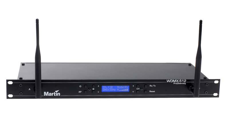
25 Display The display indicates the actual channel number, transmitter/ receiver status, access point mode and the DMX refresh rate. It also shows the signal strength of the radio communication when in receiver mode. C h. : 1 0 M o d e : R x D M X : 4 4 H z Display description N/A Ch.: Mode: DMX: Antenna Signal strength Signal strength not available (e.g. in transmitter mode). Access point mode Current channel number/ universe. Rx: Receiver mode/ Tx: Transmitter mode DMX refresh rate. - - No DMX input/ output.?? Non standard DMX input/ DMX refresh rate truncated. Buttons The keyboard offers you easy access to set all parameters of the WDMX-512 ProDiversity, such as channel number, transmitter/ receiver mode, access point mode, reset, display contrast and backlight. Button description Turns the backlight on and off. Toggles between normal and Access point mode. Increases the contrast. Decreases the contrast. Increments the current channel number by one. Decrements the current channel number by one. Toggles between receiver (Rx) and transmitter (Tx) mode. Resets the transceiver. Operation 25
26
27 STANDARD MODEL INTERFACES This section describes the user interface for the WMDX-512 Standard model. Top Panel Power LED This LED indicates that power is applied to the WDMX-512. DMX LED When power is applied to the unit the DMX LED blinks as many times as the selected channel number. If the unit is set to channel four, the LED will blink four times. The DMX LED has the following functionality. Configured as Transmitter Receiver Functionality When configured as a transmitter the DMX LED indicates that it s transmitting the wireless DMX signal. When configured as receiver the DMX LED indicates that it is receiving the wireless DMX signal. Transmitter LED Configured as Transmitter Receiver Functionality When the LED is lit the WDMX-512 is configured as a transmitter. When the LED is not lit the WDMX-512 is configured as a receiver. Standard model interfaces 27
28 Signal strength LED s Configured as Functionality Transmitter - Receiver This indicates the receiving signal level. NOTE: 1) If all the signal strength LEDs are flashing the WDMX-512 Standard is in configuration mode. 2) If the signal strength LEDs are chasing, the WDMX-512 Standard has detected a WLAN Card error. Rear panel Mains connector This is the main power connection. For protection from electric shock, the unit must be grounded. The color code for the power cord is: Color Yellow/Green Brown Blue Fuses Description Earth/Ground Live Neutral The WDMX-512 Standard comes with two fuses F1 and F2 that protects both neutral and phase. The WDMX-512 ProDiversity has a single fuse F1 protecting the phase. F1, (F2): 63mA (T) / 250V (for 230V models). F1, (F2): 125mA (T) / 250V (for 115V models). Never attempt to bypass the fuses. Always replace defective fuses with ones of the specified type and rating. RS-232 This is a serial interface and is only used to configure the WDMX-512 Standard, and the WDMX- 512 ProDiversity in Advanced mode. For further details about the configuration see Configure the WDMX-512 using HyperTerminal on page 17. DMX in When configured as a transmitter, apply a 5 pins female XLR plug from a DMX master to this input. Use the included 5 to 3 pole adaptor, if a 3 pins XLR cable is used. If configured as a receiver, apply a termination of 120 ohm between pin 2 and pin 3 to this input. Pin Description 28 Standard model interfaces
29 Pin 1 GND (shield) Pin 2 Cold (-) Pin 3 Hot (+) Pin 4 Pin 5 DMX out No Connection No Connection When configured as receiver, apply a 5 pins female XLR plug from this output to one or more DMX devices. Use the included 5 to 3 pole adaptor, if a 3 pins XLR cable is used. Remember to terminate the DMX link with a 120 ohm termination at the end of the link. If configured as a transmitter, apply a termination of 120 ohm between pin 2 and pin 3 to this output. Pin Pin 1 Description GND (shield) Pin 2 Cold (-) Pin 3 Hot (+) Pin 4 Pin 5 PGM No Connection No Connection This is for service purpose only, and should NOT be connected. Buttons These Pin buttons are located next to the connectors. Due to security reasons these buttons can only be activated by a paper clip or similar object. SET If this button is pressed for more than 3 seconds the WDMX-512 is in configuration mode and the signal LED s will be flashing/ display showing Setup using serial port. To cancel configuration mode press RST or turn the power off and on. RST If this button is pressed the WDMX-512 will reset. PCMCIA WLAN CARD (WDMX-512 Standard ONLY) Insert the PCMCIA card into this socket. Do not use other WLAN cards than the original type included in the WDMX-512 Standard package. Remove the card form the unit when it is not in use. Standard model interfaces 29
30
31 PRODIVERSITY MODEL INTERFACES The following chapter describes the user interface for the DMX-512 ProDiversity model. Front Panel Display The display indicates the actual channel number, transmitter/ receiver status, access point mode and the DMX refresh rate. It also shows the signal strength of the radio communication when in receiver mode. C h. : 1 0 M o d e : R x D M X : 4 4 H z Display description N/A Ch.: Mode: DMX: Antenna Signal strength Signal strength not available (e.g. in transmitter mode). Access point mode Current channel number/ universe. Rx: Receiver mode/ Tx: Transmitter mode DMX refresh rate. - - No DMX input/ output.?? Non standard DMX input/ DMX refresh rate truncated. Buttons The keyboard offers you easy access to set all parameters of the WDMX-512 ProDiversity, such as channel number, transmitter/ receiver mode, access point mode, reset, display contrast and backlight. Button description Turns the backlight on and off. Toggles between normal and Access point mode. Increases the contrast. Decreases the contrast. ProDiversity model interfaces 31
32 Antennas Increments the current channel number by one. Decrements the current channel number by one. Toggles between receiver (Rx) and transmitter (Tx) mode. Resets the transceiver. The WDMX-512 ProDiversity uses two external antennas. The two antennas should be connected to the reversed TNC connectors on the front panel named: A (primary) and B (secondary). The antennas operate in diversity mode, ensuring optimal sensitivity. If operating by a single external antenna, antenna A should be used, witch is the primary antenna. Rear panel Mains connector This is the main power connection. For protection from electric shock, the unit must be grounded. The color code for the power cord is: Color Yellow/Green Brown Blue Fuses Description Earth/Ground Live Neutral The WDMX-512 Standard comes with two fuses F1 and F2 that protects both neutral and phase. The WDMX-512 ProDiversity has a single fuse F1 protecting the phase. F1, (F2): 63mA (T) / 250V (for 230V models). F1, (F2): 125mA (T) / 250V (for 115V models). Never attempt to bypass the fuses. Always replace defective fuses with ones of the specified type and rating. RS-232 This is a serial interface and is only used to configure the WDMX-512 Standard, and the WDMX- 512 ProDiversity in Advanced mode. For further details about the configuration see Configure the WDMX-512 using HyperTerminal on page 17. DMX in When configured as a transmitter, apply a 5 pins female XLR plug from a DMX master to this input. Use the included 5 to 3 pole adaptor, if a 3 pins XLR cable is used. If configured as a receiver, apply a termination of 120 ohm between pin 2 and pin 3 to this input. Pin Pin 1 Description GND (shield) 32 ProDiversity model interfaces
33 Pin 2 Cold (-) Pin 3 Hot (+) Pin 4 Pin 5 DMX out No Connection No Connection When configured as receiver, apply a 5 pins female XLR plug from this output to one or more DMX devices. Use the included 5 to 3 pole adaptor, if a 3 pins XLR cable is used. Remember to terminate the DMX link with a 120 ohm termination at the end of the link. If configured as a transmitter, apply a termination of 120 ohm between pin 2 and pin 3 to this output. Pin Pin 1 Description GND (shield) Pin 2 Cold (-) Pin 3 Hot (+) Pin 4 Pin 5 PGM No Connection No Connection This is for service purpose only, and should NOT be connected. Buttons These Pin buttons are located next to the connectors. Due to security reasons these buttons can only be activated by a paper clip or similar object. SET If this button is pressed for more than 3 sec. the WDMX-512 is in configuration mode and the signal LED s will be flashing/ display showing Setup using serial port. To cancel configuration mode press RST or turn the power off and on. RST If this button is pressed the WDMX-512 will reset. ProDiversity model interfaces 33
34
35 SPECIFICATIONS WDMX-512 Standard model Mains inlet V AC/115 V AC (IEC Connector) ±7%, Power consumption W Protocol... DMX512 Communication distance...up to 200 m (666 ft), outdoor, without repeater DMX Refresh rate...approx 44 Hz DMX I/O... 5 pin XLR Expandability...up to 13 DMX-512 universes WLAN Card B, PCMCIA, Prism-II Chipset or compatible Size (h, w, d) x 195 x 125 mm (1.96 x 7.68 x 4.9 inch) Weight kg (53 oz.) Temperature operating range C ( F) ProDiversity model Mains inlet: V AC/115 V AC (IEC Connector) ±7% Power consumption W Protocol... DMX512 Communication distance...up to 300 m (1.000 ft), outdoor, without repeater DMX Refresh rate...approx 44 Hz DMX I/O...5 pin XLR Expandability...up to 13 DMX-512 universes WLAN Card B, PCMCIA, Prism-II Chipset or compatible Size (h, w, d) x 482 x 182 mm (1.73 x x 7.17 inch) Weight kg (124 oz.) Temperature operating range C ( F) Specifications 35
USER MANUAL Table of Contents
 USER MANUAL Table of Contents Safety Information 3 Specifications 4 Main Power Connection 5 DMX-512 Connection 5 Fixture Level 6 Set Up 6 Operation Options 7 Connection 8 Rigging the Fixture 9 Cleaning
Rubix RGB 3D Panel. User Manual. Order code: LEDJ476
 Rubix RGB 3D Panel User Manual Order code: LEDJ476 Safety advice WARNING FOR YOUR OWN SAFETY, PLEASE READ THIS USER MANUAL CAREFULLY BEFORE YOUR INITIAL START-UP! Before your initial start-up, please make
EA3012 TRANSCONDUCTANCE AMPLIFIER OPERATION MANUAL
 EA3012 TRANSCONDUCTANCE AMPLIFIER Ü EA3012 Transconductance Amplifier Operation Manual Version 2.00 Dec 2011 All product names are trademarks of their respective companies Guarantee and service Transmille
T L Audio CRIMSON SERIES. User Manual EQ-3011 EQUALISER. Tony Larking Professional Sales Limited, Letchworth, England.
 T L Audio CRIMSON SERIES User Manual EQ-3011 EQUALISER Tony Larking Professional Sales Limited, Letchworth, England. Tel: 01462 490600. International +44 1462 490600. Fax: 01462 490700. International +44
RMV25 / RMV50 RMU25 / RMU45
 RMV25 / RMV50 RMU25 / RMU45 Owner's Manual TABLE OF CONTENTS INTRODUCTION... 3 FCC Requirements... 3 SAFETY WARNING INFORMATION... 3 CONTROLS and INDICATORS... 5 FRONT PANEL... 5 LCD Icons and Indicators...
LED PowerBlinder 4 ORDERCODE 41320
 LED PowerBlinder 4 ORDERCODE 41320 Congratulations! You have bought a great, innovative product from Showtec. The Showtec LED PowerBlinder brings excitement to any venue. Whether you want simple plug-&-play
INSTALLATION MANUAL ECA-70VMINI-60W ECA-70VMINI-60W L VOLUME SPEAKER OUTPUTS 12VDC IN + L+ L- GND R+ R- S GND GND Tx Rx
 INSTALLATION MANUAL ECA-70VMINI-60W ECA-70VMINI-60W L VOLUME R 12VDC IN BALANCED IN STEREO IN UNBALANCED IN SERVICE STATUS IR RS-232 + L+ L- GND R+ R- S GND GND Tx Rx SPEAKER OUTPUTS + page 2 CAUTION Risk
SI-125 Power Amplifier Manual 6205 Kestrel Road; Mississauga, Ontario; Canada; L5T 2A1 November 2016, Rev 0.5
 SI-125 Power Amplifier Manual 6205 Kestrel Road; Mississauga, Ontario; Canada; L5T 2A1 November 2016, Rev 0.5 Phone: (905) 564-0801 Fax: (905) 564-0806 www.telecor.com E:\T2-108\T2-M108-ABC\T2-M108-B.doc/AD
T L Audio. User Manual EQ1 VALVE EQUALISER. Tony Larking Professional Sales Limited, Letchworth, England.
 T L Audio User Manual EQ1 VALVE EQUALISER Tony Larking Professional Sales Limited, Letchworth, England. Tel: 01462 490600, International +44 1462 490600. Fax: 01462 490700, International +44 1462 490700.
T L Audio CRIMSON SERIES. User Manual EQ-3012 PARAMETRIC EQUALISER. Tony Larking Professional Sales Limited, Letchworth, England.
 T L Audio CRIMSON SERIES User Manual EQ-3012 PARAMETRIC EQUALISER Tony Larking Professional Sales Limited, Letchworth, England. Tel: 01462 490600. International +44 1462 490600. Fax: 01462 490700. International
User Instructions. Model PS-2001L. Power Supply. Model SPS Power Supply. Audiocom Intercom Systems Rev. A, 4/2001.
 User Instructions PS-00L Model PS-00L Power Supply SPS-00 Volume Model SPS-00 Power Supply Audiocom Intercom Systems 950-7699-000 Rev. A, /00 FCC Statement This equipment uses, and can radiate radio frequency
Contents. Warranty and Disclaimer 2 Introduction 3
 Contents Warranty and Disclaimer 2 Introduction 3 Physical Dimensions Board Layout 4 Usage Using the Relay board 5 Setting the start address 5 Configuration Jumper 6 Using the Relays 7 Using the DMX connectors
1. FEATURES ON THE CONTROL PANEL FEATURES ON THE BACK PANEL General Options SAFETY INFORMATION...
 LOGIBIT 1200 MANUAL Table of Contents TABLE OF CONTENTS 1. FEATURES ON THE CONTROL PANEL... 1 2. MENU STRUCTURE... 2 2.1 Function keys... 2 2.2 Menu points... 2 2.3 Illustration of menu structure... 5
Instruction Manual Model M Switch, DPDT, Manual Select
 Instruction Manual Model 1582-70M Switch, DPDT, Manual Select November 2018 Rev 0 STATUS MODEL 1582 CROSS TECHNOLOGIES INC. MANUAL SELECT POWER Data, drawings, and other material contained herein are proprietary
Q-Tech. Q-Tech Commercial Series QTA 1360P/1480P Power Amplifiers. User Manual
 Q-Tech Power Amplifiers WARNING THIS APPLIANCE MUST BE EARTHED General Installation DO NOT run unbalanced high impedance microphone cables near mains, data, telephone or 70/100V line cables. DO NOT run
Contents. Warranty and Disclaimer 2 Introduction 3
 Contents Warranty and Disclaimer 2 Introduction 3 Physical Dimensions Board Layout 4 Servo connections 5 Using the Serv8 Usage 6 Setting the start address 7 Setting the pulse width 8 Using the configuration
DA216S DISTRIBUTION AMPLIFIER
 DISTRIBUTION AMPLIFIER IMPORTANT SAFETY INSTRUCTIONS 1. Read these instructions. 2. Keep these instructions. 3. Heed all warnings. 4. Follow all instructions. 5. Do not use this apparatus near water. 6.
MC450/MC650 (MC750) OPERATING INSTRUCTIONS
 OPERATING INSTRUCTIONS") MC450/MC650 (MC750) OPERATING INSTRUCTIONS MC 2 AUDIO Ltd., Units 6 & 7 Kingsgate, Heathpark Industrial Estate, HONITON, Devon EX14 1YG England Tel: ++(0)1404.44633 Fax: ++(0)1404.44660 www.mc2-audio.co.uk
MC450/MC650 (MC750) OPERATING INSTRUCTIONS MC 2 AUDIO Ltd., Units 6 & 7 Kingsgate, Heathpark Industrial Estate, HONITON, Devon EX14 1YG England Tel: ++(0)1404.44633 Fax: ++(0)1404.44660 www.mc2-audio.co.uk
FORTUS 360mc/400mc and FDM 360mc/400mc 3D Production System. Site Preparation Guide Rev E
 FORTUS 360mc/400mc and FDM 360mc/400mc 3D Production System Site Preparation Guide 107167-0005 Rev E Liability Statement The information in this document is subject to change without notice. Stratasys,
Professional UHF Rechargeable Wireless Microphone System POWER ON/OFF BATTERY CHARGE. Green Light (Full) Better Music Builder DOWN VOLUME
 Better Music Builder DOWN VOLUME") Green Light (Full) KARAOKE Professional UHF Rechargeable Wireless Microphone System VM-93C Operating Instructions UHF Frequency 64 Selectable POWER ON/OFF CHARGE Better Music Builder VM-93C CHARGER UHF
Green Light (Full) KARAOKE Professional UHF Rechargeable Wireless Microphone System VM-93C Operating Instructions UHF Frequency 64 Selectable POWER ON/OFF CHARGE Better Music Builder VM-93C CHARGER UHF
W-DMX G4. BlackBox and WhiteBox F-1 BlackBox and WhiteBox R-512 BlackBox and WhiteBox F-2 Micro F-1 Lite Micro R-512 Lite ProBox F-2500.
 W-DMX G4 BlackBox and WhiteBox F-1 BlackBox and WhiteBox R-512 BlackBox and WhiteBox F-2 Micro F-1 Lite Micro R-512 Lite ProBox F-2500 User Manual W-DMX G4 User Manual Issue date: 2012-02 Edition: 1 Subject
EPA152/252/502. User Manual.
 EPA152/252/502 User Manual www.audac.eu ADDITIONAL INFORMATION This manual is put together with much care, and is as complete as could be on the publication date. However, updates on the specifications,
(Wireless Solution)
") Wireless Solution 21.9687.1860 (Wireless Solution) 21.9687.1861 (Lumen Radio) 21.9687.1862 (City Theatrical) Wireless DMX Receivers Installation & User s Manual For use with VL440 Spot, VL770 Spot, VL880
Wireless Solution 21.9687.1860 (Wireless Solution) 21.9687.1861 (Lumen Radio) 21.9687.1862 (City Theatrical) Wireless DMX Receivers Installation & User s Manual For use with VL440 Spot, VL770 Spot, VL880
Power Genius XL User Manual rev 10.
 Power Genius X User Manual rev 10. 1/23 Table of Contents 0. Important notice...3 1. Unpacking...5 1.1. Front Panel...5 1.2. Back Panel...6 1.3. BCD/PTP connector pinout...8 2. Using with Radios...9 2.1.
Installation and Operation Manual MSI. Multi-Sensor Interface Hub. Interface Module for all Sensors Network and Wireless CAUTION
 Installation and Operation Manual MSI Multi-Sensor Interface Hub Interface Module for all Sensors Network and Wireless CAUTION This equipment complies with the limits for a Class B digital device, pursuant
FO-TX 2-EC FO-TX 2-OPT FO-RX 2-EC
 Revision date: 07/2013 Instruction manual FO-TX 2-EC FO-TX 2-OPT FO-RX 2-EC FO-TX 2-EC FO-TX 2-OPT FO-RX 2-EC Short description These devices are designed to extend radio microphone remote receiving aerials
I n s ta l l at i o n M a n u a l f o r T E D P r o H o m e T E D P r o L i t e A B C Rev 4.0
 I n s t a l l a t i o n M a n u a l f o r T E D P r o H o m e T E D P r o L i t e A B C Rev 4.0 IMPORTANT: The installation of your TED Pro Home system is a several-step process. The 1st step is the installation
32 CHANNEL SELECTABLE CH MHZ DOWN VOLUME
 KARAOKE Professional UHF Wireless Microphone System VM-92U Operating Instructions UHF Frequency 64 Selectable Better Music Builder UHF MIC WIRELESS SYSTEM VM-92U 32 CHANNEL SELECTABLE 248 13.10 CH MHZ
EXECUTE Shiloh Road Alpharetta, Georgia (770) FAX (770) Toll Free
 FAX (770) Toll Free") Instruction Manual Model 1586-06 RF Attenuator May 2009 Rev A 1 2 3 12.5 53.5 16.3 MODEL 1586 RF ATTENUATOR CROSS TECHNOLOGIES INC. EXECUTE PS1 PS2 Data, drawings, and other material contained herein are
Instruction Manual Model 1586-06 RF Attenuator May 2009 Rev A 1 2 3 12.5 53.5 16.3 MODEL 1586 RF ATTENUATOR CROSS TECHNOLOGIES INC. EXECUTE PS1 PS2 Data, drawings, and other material contained herein are
Aria Wireless DMX. User guide
 Aria Wireless DMX User guide CONTENTS INTRODUCTION...2 Welcome 2 Safety 2 INSTALLATION...3 Mounting 3 Connections 4 Power and control wiring 5 OPERATION...6 The control panel 7 Transferring multiple universes
Disclaimers. Important Notice
 Disclaimers Disclaimers Important Notice Copyright SolarEdge Inc. All rights reserved. No part of this document may be reproduced, stored in a retrieval system, or transmitted, in any form or by any means,
USER MANUAL. MODEL 2017A RS-232 to 20ma Current Loop Converter. SALES OFFICE (301) TECHNICAL SUPPORT (301)
 TECHNICAL SUPPORT (301)") USER MANUAL MODEL 2017A RS-232 to 20ma Current Loop Converter Part# 07M2017A-A Doc# 073021UA Revised 10/15/93 SALES OFFICE (301) 975-1000 TECHNICAL SUPPORT (301) 975-1007 http://www.patton.com 1.0 WARRANTY
USER MANUAL MODEL 2017A RS-232 to 20ma Current Loop Converter Part# 07M2017A-A Doc# 073021UA Revised 10/15/93 SALES OFFICE (301) 975-1000 TECHNICAL SUPPORT (301) 975-1007 http://www.patton.com 1.0 WARRANTY
Contents. Warranty and Disclaimer 2
 Contents Warranty and Disclaimer 2 Physical Dimensions Board Layout 3 Usage Using the PWM board 4 Setting the start address 4 Dimming LED s 5,6 Typical hookup 7 Terminator 8 Troubleshooting Ground, termination,
W-DMX G4 MK I and MK II USER MANUAL
 W-DMX G4 MK I and MK II USER MANUAL BlackBox and WhiteBox F-1 BlackBox and WhiteBox R-512 BlackBox and WhiteBox F-2 Micro F-1 Lite Micro R-512 Lite ProBox F-2500 W-DMX G4(S) User Manual Issue date: 2013-10
WIRELESS DMX TRANSMITTER OR RECEIVER BOX (AIRDMX) USER GUIDE December 2012 Version 1.0
 USER GUIDE December 2012 Version 1.0") WIRELESS DMX TRANSMITTER OR RECEIVER BOX (AIRDMX) USER GUIDE 9966 - December 2012 Version 1.0 English AirBOX-ER1- Wireless DMX transmitter or receiver box (AirDMX) 1 - Safety information Important safety
WIRELESS DMX TRANSMITTER OR RECEIVER BOX (AIRDMX) USER GUIDE 9966 - December 2012 Version 1.0 English AirBOX-ER1- Wireless DMX transmitter or receiver box (AirDMX) 1 - Safety information Important safety
SIR-WRR1. User's Guide SIRIUS Echo Antenna. Signal Repeater System Accessory
 SIR-WRR1 User's Guide SIRIUS Echo Antenna Signal Repeater System Accessory Desktop SIRIUS Docking Echo Station Antenna FCC NOTICE: This device complies with part 15 of the FCC Rules and with RSS-210 of
M-300 Mono power amplifier User s guide
 M-300 Mono power amplifier User s guide M-300 Mono power amplifier User s guide Specifications: Contents: Power output: 8Ω: 290W, 0.01% THD SPECIFICATIONS Page 2 Input impedance: Gain: 4Ω: 580W, 0.01%
Radio Link Starter Kit
 Radio Link Starter Kit Installation Manual BARTLETT Instrument Co. 1032 Avenue H Fort Madison, IA 52627 319-372-8366 www.bartinst.com Table of Contents Radio Link Starter Kit Manual... 3 System Requirements...
ECI 6D. Balanced Integrated Amplifier. Owner's Manual. (with a built-in DAC) ENGLISH
 ENGLISH") ECI 6D Balanced Integrated Amplifier (with a built-in DAC) Owner's Manual EN ENGLISH Unpacking the ECI 6D Immediately upon receipt of the ECI 6D, inspect the carton for possible damage during shipment.
ECI 6D Balanced Integrated Amplifier (with a built-in DAC) Owner's Manual EN ENGLISH Unpacking the ECI 6D Immediately upon receipt of the ECI 6D, inspect the carton for possible damage during shipment.
W-DMX G4 MK I and MK II USER MANUAL
 W-DMX G4 MK I and MK II USER MANUAL BlackBox and WhiteBox F-1 BlackBox and WhiteBox R-512 BlackBox and WhiteBox F-2 Micro F-1 Lite Micro R-512 Lite ProBox F-2500 Contents Contents W-DMX G4(S) User Manual
USER'S MANUAL. Model : K
 USER'S MANUAL Model : 2000-64K TM GINA MODEL 2000-64K Overview GINA Model 2000-64K is a stand-alone, high frequency data transceiver using spread spectrum technology. GINA 2000-64K capabilities include
T L Audio INDIGO SERIES. User Manual VP-2051 VALVE VOICE PROCESSOR. Tony Larking Professional Sales Limited, Letchworth, England.
 T L Audio INDIGO SERIES User Manual VP-2051 VALVE VOICE PROCESSOR Tony Larking Professional Sales Limited, Letchworth, England. Tel: 01462 490600. International +44 1462 490600. Fax: 01462 490700. International
DM 800H Twin Handheld UHF System (863.0Mhz-865.0Mhz)
") DM 800H Twin Handheld UHF System (863.0Mhz-865.0Mhz) User Manual Order code: MIC78 Safety advice WARNING FOR YOUR OWN SAFETY, PLEASE READ THIS USER MANUAL CAREFULLY BEFORE YOUR INITIAL START-UP! Before
DM 800H Twin Handheld UHF System (863.0Mhz-865.0Mhz) User Manual Order code: MIC78 Safety advice WARNING FOR YOUR OWN SAFETY, PLEASE READ THIS USER MANUAL CAREFULLY BEFORE YOUR INITIAL START-UP! Before
Installation & Quick Start Guide AIT2000 Class B AIS Transponder
 Installation & Quick Start Guide AIT2000 Class B AIS Transponder QUICK START AIT2000 - VR1.01 1. Introduction Congratulations on the purchase of your AIT2000 Class B AIS Transponder. It is recommended
Wireless Z-Wave Control ZRP-100US Z-Wave Repeater USER MANUAL. Introduction
 Wireless Z-Wave Control ZRP-100US Z-Wave Repeater USER MANUAL Introduction Thank you for choosing ZRP-100 Z-Wave Repeater product! ZRP-100 is a Z-Wave repeater with best RF performance to repeat Z-Wave
HT1100 Satellite Modem User Guide
 HT1100 Satellite Modem User Guide 1039650-0001 Revision C October 11, 2013 11717 Exploration Lane, Germantown, MD 20876 Phone (301) 428-5500 Fax (301) 428-1868/2830 Copyright 2013 Hughes Network Systems,
I n s t a l l a t i o n M a n u a l. T E D P r o L i t e A B C. f o r. Shop for The Energy Detective products online at: Rev 3.
 Rev 3.5 I n s t a l l a t i o n M a n u a l f o r T E D P r o H o m e T E D P r o L i t e A B C Shop for The Energy Detective products online at: 1.877.766.5412 IMPORTANT: The installation of your TED
NSPL-500. AIS/VHF antenna splitter. User Manual ENGLISH.
 NSPL-500 AIS/VHF antenna splitter User Manual ENGLISH www.bandg.com www.simrad-yachting.com www.lowrance.com Preface As Navico is continuously improving this product, we retain the right to make changes
TRANSFORMER HD-HAMPTON HAMPTONBAY.COM
 Item #1001 510 115 Model DIY-600PS USE AND CARE GUIDE TRANSFORMER Questions, problems, missing parts? Before returning to the store, call HamptonBay Customer Service 8 a.m. - 7 p.m., EST, Monday Friday,
TMP40. User Manual.
 TMP40 User Manual www.audac.eu ADDITIONAL INFORMATION This manual is put together with much care, and is as complete as could be on the publication date. However, updates on the specifications, functionality
KanAtoN 1 / 3 AIS Transponder. Installation Manual
 Orolia S.A.S. Z.I. des Cinq Chemins 56520 GUIDEL - FRANCE Telephone: +33 (0)2 97 02 49 49 Fax: +33 (0)2 97 65 00 20 Web : http://www.mcmurdomarinesystems.com An Orolia Group Business DATE : 20/072012 KanAtoN
Lifetime Power Energy Harvesting Development Kit for Wireless Sensors User s Manual - featuring PIC MCU with extreme Low Power (XLP) Technology
 Technology") P2110-EVAL-01 Lifetime Power User s Manual - featuring PIC MCU with extreme Low Power (XLP) Technology Overview The Lifetime Power is a complete demonstration and development platform for creating battery-free
P2110-EVAL-01 Lifetime Power User s Manual - featuring PIC MCU with extreme Low Power (XLP) Technology Overview The Lifetime Power is a complete demonstration and development platform for creating battery-free
Warning: Electrical Hazard... 3 Safety Instruction Sheet for STG Product Overview What s in the box?... 4
 STG-2412 User Guide Warning: Electrical Hazard... 3 Safety Instruction Sheet for STG-2412... 3 Product Overview... 4 What s in the box?... 4 Using STG-2412 for Mixing, Processing, and Recording... 5 Software
AIT2000 CLASS B AIS TRANSPONDER
 IMPORTANT NOTE The USB cable of the AIT2000 is designed to be used for configuring/programming the unit during installation and not for permanent connection to the boat s Navigation PC. If you intend to
Active Transmitter Combiner 8:1 AC 3200-II. Instruction manual
 Active Transmitter Combiner 8:1 AC 3200-II Instruction manual Contents Contents Important safety instructions... 2 The AC 3200-II active transmitter combiner 8:1... 4 Delivery includes... 4 Connection
WRM-10 TM TRANSFORMER WINDING RESISTANCE METER
 WRM-10 TM TRANSFORMER WINDING RESISTANCE METER USER S MANUAL Vanguard Instruments Company, Inc. 1520 S. Hellman Ave. Ontario, California 91761, USA TEL: (909) 923-9390 FAX: (909) 923-9391 June 2009 Revision
TOA 900 SERIES POWER AMPLIFIER P-924A
 Operation Instruction Manual TOA 900 SERIES POWER AMPLIFIER P-924A Features General Descriptions 1 Wide frequency response; 20 20,000 Hz, ±1dB 2 Low distortion and noise level 3 Excellent output regulation
mat-30 HF-SSB Automatic Antenna Tuner Instruction Manual Version V1.0
 INTRODUCTION mat-30 HF-SSB Automatic Antenna Tuner Instruction Manual Version V1.0 The mat-30 is an automatic tuner intended for use with modern Yaesu transceivers. It works with some Yaesu transceiver
EPA104/254. User Manual.
 EPA104/254 User Manual www.audac.eu ADDITIONAL INFORMATION This manual is put together with much care, and is as complete as could be on the publication date. However, updates on the specifications, functionality
WEL-200 O P E R A T I N G I N S T R U C T I O N S W I R E L E S S E D G E L I N K
 O P E R A T I N G I N S T R U C T I O N S WEL-200 TM W I R E L E S S E D G E L I N K 4564 Johnston Parkway, Cleveland, Ohio 44128 P. 800 426 9912 F. 216 518 9884 Sales Inquiries: salessupport@emxinc.com
User Guide. Keysight N6850A Broadband Omnidirectional Antenna
 User Guide Keysight N6850A Broadband Omnidirectional Antenna Notices Keysight Technologies, Inc. 2012-2015 No part of this manual may be reproduced in any form or by any means (including electronic storage
PC Tune PC Tune Test Procedures for 5100 Series Portable Radios
 PC Tune PC Tune Test Procedures for 5100 Series Portable Radios Part Number 002-9998-6513014 August 2008 Copyright 2006, 2007, 2008 by EFJohnson Technologies The EFJohnson Technologies logo, PC Configure,
Quick Start Guide. ELPRO 905U-L-T Wireless I/O Transmitter Unit. man_905u-l-t_quickstart_v1.9.doc
 Quick Start Guide ELPRO 905U-L-T Wireless I/O Transmitter Unit man_905u-l-t_quickstart_v1.9.doc About this document This document is the and contains the following sections: Section Basic steps for using
Radio Link Starter Kit
 Radio Link Starter Kit Installation Manual BARTLETT Instrument Co. 1032 Avenue H Fort Madison, IA 52627 319-372-8366 www.bartinst.com Table of Contents Radio Link Starter Kit Manual... 3 System Requirements...
Disclaimers. Important Notice
 Disclaimers Disclaimers Important Notice Copyright SolarEdge Inc. All rights reserved. No part of this document may be reproduced, stored in a retrieval system, or transmitted, in any form or by any means,
TOA PROFESSIONAL POWER AMP
 Operating Instruction Manual TOA PROFESSIONAL POWER AMP Model P-150M, P-300M TOA ELECTRIC CO, LTD. KOBE, JAPAN Contents Precautions... 2 General Description... 2 Features... 3 Specifications... 4~5 Performance
AcuMesh Wireless RS485 Network. User's Manual SOLUTION
 AcuMesh Wireless RS485 Network User's Manual AN SOLUTION ACUMESH - WIRELESS METERING SYSTEM COPYRIGHT 2015 V1.2 This manual may not be altered or reproduced in whole or in part by any means without the
AW2400iTR USER S MANUAL 2.4 GHz Indoor Wireless Ethernet Radio
 USER S MANUAL 2.4 GHz Indoor Wireless Ethernet Radio Industrial-grade, long-range wireless Ethernet systems AvaLAN W I R E L E S S Thank you for your purchase of the AW2400iTR Indoor Wireless Ethernet
INSTALLATION AND OPERATING MANUAL
 INSTALLATION AND OPERATING MANUAL FOR RBDA-PCS-1/25W-90-A INDOOR REPEATER TABLE OF CONTENTS PARAGRAPH PAGE NO BDA OVERVIEW 3 BDA BLOCK DIAGRAM DESCRIPTION 3 FCC INFORMATION FOR USER 3 BDA BLOCK DIAGRAM
INSTRUCTION MANUAL. IBRit - rf1 - usb PC - Station for wireless Data transmission. M e s s t e c h n i k. Messtechnik GmbH & Co.
 M e s s t e c h n i k INSTRUCTION MANUAL PC - Station for wireless Data transmission Document No. : D1F604 001 Version : April 2006 Copyright : IBR Messtechnik GmbH & Co. KG Contents 1. Introduction 1.1
DPA74/154 AUDAC PROFESSIONAL AUDIO EQUIPMENT. DPA74/154 Quad Channel Class-D Amplifier. User Manual & Installation Guide
 DPA74/154 PROFESSIONAL AUDIO EQUIPMENT DPA74/154 Quad Channel Class-D Amplifier AUDAC User Manual & Installation Guide AUDAC PROFESSIONAL AUDIO EQUIPMENT User Manual & Installation Guide AUDAC http://www.audac.eu
VFSC9 ELECTRONIC SPEED CONTROLLER. Mounting and operating instructions
 ELECTRONIC SPEED CONTROLLER Mounting and operating instructions Table of contents SAFETY AND PRECAUTIONS 3 PRODUCT DESCRIPTION 4 ARTICLE CODES 4 INTENDED AREA OF USE 4 TECHNICAL DATA 4 STANDARDS 5 WIRING
RM24100D. Introduction. Features. 2.4GHz 100mW RS232 / RS485 / RS422 DSSS Radio Modem (IEEE compliant) Operating Manual English 1.
 Operating Manual English 1.") RM24100D 2.4GHz 100mW RS232 / RS485 / RS422 DSSS Radio Modem (IEEE 802.15.4 compliant) Operating Manual English 1.09 Introduction The RM24100D radio modem acts as a wireless serial cable replacement and
RM24100D 2.4GHz 100mW RS232 / RS485 / RS422 DSSS Radio Modem (IEEE 802.15.4 compliant) Operating Manual English 1.09 Introduction The RM24100D radio modem acts as a wireless serial cable replacement and
DMP40. User Manual.
 DMP40 User Manual www.audac.eu ADDITIONAL INFORMATION This manual is put together with much care, and is as complete as could be on the publication date. However, updates on the specifications, functionality
SL Slave Amplifiers. User Manual. Order codes: CRAM37 - SL V 4 x 60W CRAM22 - SL V 4 x 120W CRAM23 - SL V 4 x 240W
 SL Slave Amplifiers User Manual Order codes: CRAM SL V x W CRAM SL V x W CRAM SL V x W Safety advice WARNING FOR YOUR OWN SAFETY, PLEASE READ THIS USER MANUAL CAREFULLY BEFORE YOUR INITIAL STARTUP! Before
XD-V30 Digital Wireless System
 XD-V30 Digital Wireless System Pilot s Handbook Manuel de pilotage Pilotenhandbuch Pilotenhandboek Manual del Piloto 取扱説明書 See www.line6.com/manuals for Advance Guide 40-00-0286 Advanced Users Guide available
RTK Base Station Configuration and Utilities. Table of Contents
 RTK Base Station Configuration and Utilities Table of Contents Introduction:... 2 LED Functionality:... 2 Initial Survey:... 2 Additional Surveys:... 3 Power Up At a Previously Surveyed Location:... 3
Page 1 T O O L S A N D M AT E R I A L S R E Q U I R E D. 1. Screwdriver 2. Carpenter's level 3. Electrical Tape PA R T S L I S T. A.
 T O O L S A N D M AT E R I A L S R E Q U I R E D 1. Screwdriver 2. Carpenter's level 3. Electrical Tape PA R T S L I S T A. Cabinet B. Wood Screw X4 C. Plastic wire connector x3 Page 1 I M P O R TA N T
14 CHANNEL FAMILY RADIO SYSTEM MODEL # FR142
 14 CHANNEL FAMILY RADIO SYSTEM MODEL # FR142 2001 Audiovox Electronics Corp., Hauppauge, NY 11788 Printed in China 128-6020 052FR142104 BEFORE OPERATING THIS PRODUCT PLEASE READ THESE INSTRUCTIONS COMPLETELY
XD-V70 Wireless Receiver
 XD-V70 Wireless Receiver Pilot s Handbook Manuel de pilotage Pilotenhandbuch Pilotenhandboek Manual del Piloto 取扱説明書 See www.line6.com/manuals for Advance Guide Advanced Users Guide available @ www.line6.com/manuals
DPAfour125, DPAfour250 AMPLIFIERS. Operating Manual
 DPAfour125, DPAfour250 AMPLIFIERS Operating Manual Operating manual, DPA Series DPA-10UMS01-V01R04 version revision date 01 02 24-02-2012 www.ateis-europe.com ATEÏS Europe BV - Sydneystraat 42-3047BP ROTTERDAM
DSP40. User Manual.
 DSP40 User Manual www.audac.eu ADDITIONAL INFORMATION This manual is put together with much care, and is as complete as could be on the publication date. However, updates on the specifications, functionality
Digivance External Notch Filter Installation Instructions
 Digivance External Notch Filter Installation Instructions ADCP-75-244 Issue 1 12/2007 22419-A External Notch Filter Content Page INTRODUCTION............................................................
LIGHTCASTER W-DMX. 2.4Ghz W-DMX Wireless System
 LIGHTCASTER W-DMX 2.4Ghz W-DMX Wireless System Blizzard Lighting, LLC www.blizzardlighting.com Waukesha, WI USA Copyright (c) 2014 1. GETTING STARTED What s In The Box? 1 x Transceiver or Receiver Unit
USB Multifunction Arbitrary Waveform Generator AWG2300. User Guide
 USB Multifunction Arbitrary Waveform Generator AWG2300 User Guide Contents Safety information... 3 About this guide... 4 AWG2300 specifications... 5 Chapter 1. Product introduction 1 1. Package contents......
Back to Operator Manual Index MX50 OPERATORS MANUAL. DRAWMER MX50 Dual De-Esser SAFETY CONSIDERATIONS
 1 of 6 1/31/2005 2:44 PM Back to Operator Manual Index MX50 OPERATORS MANUAL : SAFETY CONSIDERATIONS INTRODUCTION INSTALLATION CONTROL DESCRIPTION OPERATION TECHNICAL SPECIFICATIONS DRAWMER MX50 Dual De-Esser
Important Safety Information
 OWNER'S MANUAL Important Safety Information 1. Read these instructions. 2. Keep these instructions. 3. Heed all warnings. 4. Follow all instructions. 5. Do not use this apparatus near water. 6. Clean only
Thank you for buying this AIS antenna splitter.
 Thank you for buying this AIS antenna splitter. This product has been engineered to offer you the highest level of performance and durability and we hope that it will provide many years of reliable service.
Telex. User Instructions. Model SPS2000A Power Supply Audiocom Intercom Systems SPS2000A. Volume RESET
 R Telex User Instructions SPS000A RESET Volume Model SPS000A Power Supply Audiocom Intercom Systems FCC Statement This equipment uses, and can radiate radio frequency energy that may cause interference
Revision WI.232FHSS-25-FCC-R and RK-WI.232FHSS-25-FCC-R USER S MANUAL
 Revision 1.0.3 WI.232FHSS-25-FCC-R and RK-WI.232FHSS-25-FCC-R USER S MANUAL RADIOTRONIX, INC. WI.232FHSS-25-FCC-R/ RK-WI.232FHSS-25-FCC-R USER S MANUAL Radiotronix 905 Messenger Lane Moore, Oklahoma 73160
2.4GHZ WIRELESS SYSTEM FOR POLICE VIDEO RECORDING
 PW24-2 2.4GHZ WIRELESS SYSTEM FOR POLICE VIDEO RECORDING USER GUIDE Revision B Page 1 of 8 10/11/06 TABLE OF CONTENTS 1. Quick Set Up and Operation... 3 2. Installation... 4 3. Guidelines For Best Performance...
241 Winch 10 Users Manual
 241 Winch 10 Users Manual WWW.WAHLBERG.DK TELEPHONE +45 86 18 14 20 EMAIL: sales@wahlberg.dk Index: TECHNICAL SPECIFICATIONS: 3 GENERAL: 4 PRODUCT CONTENT: 4 DESCRIPTION: 4 AREA OF USE:... 5 OVERVIEW:
On-Line Cardio Theater Wireless Digital Transmitter Installation and Instruction Manual
 On-Line Cardio Theater Wireless Digital Transmitter Installation and Instruction Manual Full installation instructions accompany your Cardio Theater equipment order. This On-Line version of our Installation/Instruction
Transmitter. User Manual. Firmware version 1.0 and greater
 ProRF SPC Transmitter User Manual Firmware version 1.0 and greater FCC NOTICE This equipment has been tested and found to comply with the limits for a class B digital device, pursuant to part 15 of the
ECA COMMERCIAL AMPLIFIER OWNER S MANUAL ECA-70MIXAMP V / 70V / 4Ω Amplifier ECA-70MIXAMP-1-60 OUTPUT LEVEL POWER MASTER MIC 1
 OWNER S MANUAL ECA COMMERCIAL AMPLIFIER ECA-MIXAMP--6 V / V / Ω Amplifier TEMP PROT OUTPUT LEVEL ECA-MIXAMP--6 6 POWER MIC MIC MIC MIC AUX AUX BASS TREBLE 5 5 5 5 5 6 6 6 6 6 MASTER 5 6 ON OFF + - + -
Installation Instructions
 SYSTXBBSAM01 EVOLUTION SYSTEM ACCESS MODULE Installation Instructions NOTE: Read the entire instruction manual before starting the installation. pointsett U.S. Pat No. 7,415,102 Fig. 1 - Evolution System
Quick Start Guide. ELPRO 905U-L-T Wireless I/O Transmitter Unit. man_905u-l-t_quickstart_v1-7.doc
 Quick Start Guide ELPRO 905U-L-T Wireless I/O Transmitter Unit man_905u-l-t_quickstart_v1-7.doc ELPRO 905U-L-T Wireless I/O Transmitter Unit Quick Start Guide About this document This document is the ELPRO
8 Channel, DMX to 0 10 volt, Decoder board
 8 Channel, DMX to 0 10 volt, Decoder board Allows DMX512 digital protocol to control analog devices that require a 0-10VDC control voltage. Upgrade 0-10 volt analog dimmers, use with motor controllers
Effective: June, 2000 EX-1821 Satellite Display Unit Receiver Installation Manual Models: 4643-*-* 4644-*-9 Since 1937
 Effective: June, 2000 LevelPRO Satellite Display Unit Receiver Installation Manual Models: 4643-*-* 4644-*-9 Since 1937 The information contained in this manual was accurate at the time of release. Specifications
User Manual VOLUME PTT 1 MIC/LINE 2 MIC/LINE 3 MIC/LINE 4 MIC/LINE 5 MIC/LINE 6 MIC/LINE 7 MIC/LINE 8 MIC/LINE 9 MIC/LINE 10 LEVEL LEVEL TREBLE 6 MIC
 + 7 54 ZM 0 Audio Mixer User Manual www.cleveracoustics.co.uk CAUTION RISK OF ELECTRIC SHOCK DO NOT OPEN. NO USER SERVICABLE PARTS INSIDE WARNING: TO REDUCE THE RISK OF FIRE OR ELECTRIC SHOCK. DO NOT EXPOSE