SV-MESH Mesh network series Catalogue
|
|
|
- Imogen Francis
- 6 years ago
- Views:
Transcription

1
2 Catalogue 1. Description Features Applications Block Diagram Electrical Characteristics Operation... 5 Power on Reset... 5 Working mode... 6 Router mode... 8 Setting Mode... 9 Communication Protocol: Parameters Description: Sleep mode RSSI index Typical connections: Pin Definition: Accessories: Mechanical Dimensions: Order information: FAQ: Note: Revision History Revision Date Comment V First release TEL: FAX: sales@nicerf.com 第 2 页共 29 页
3 1. Description SV-MESH series are ultra long distance MESH network data transceiver modules, which adopts the high performance Silicon Labs Chips. They have NODE and ROUTER working modes, can be as repeaters automatically. It is easy to build network without blind area or distance limitation. To avoid the interference, SV-MESH provides 40 frequency channels and configurable Net ID. SV-MESH is flexible but easy to use, it comes with many parameters, such as: frequency, data rate, output power, Net ID, Node ID. Users can configure the parameters through PC or customer s own device. 2. Features Repeat automatically RSSI GFSK modulation TTL/RS232/RS485/USB for option 40 channels Max output power: 100mw~5W for option 4 bytes Net ID Frequency band: 433/470/868/915Mhz for option Default 2 bytes Node ID Sensitivity up to -121 dbm Serial parameters configurable Working temperature: -40 ~ +85 C 3. Applications Robot control Access control system Remote control telemetry Remote meter reading Industrial data acquisition Security system Wireless data communication Home automation TEL: FAX: sales@nicerf.com 第 3 页共 29 页


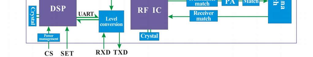
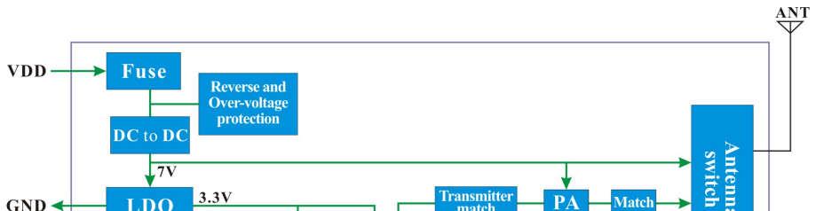
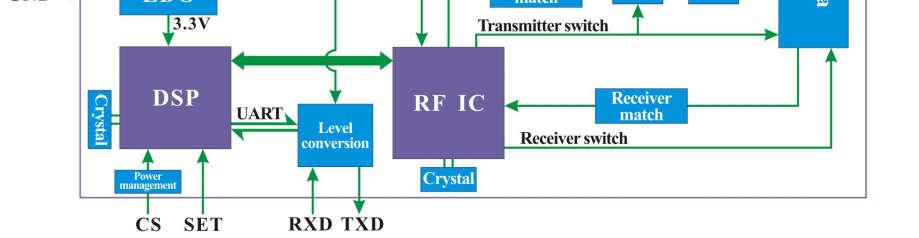
4 4. Block Diagram 100mW 500mW 2W Series 3W 5W Series TEL: FAX: 第 4 页共 29 页
5 5. Electrical Characteristics Note:High quality 3.3V LDO is integrated, and Pin CS / SET is 3.3V interface. TXD/RXD is also 3.3V for TTL Parameters Min. Typ. Max. Unit Condition Working condition Voltage range port Current consumption Sleep current < 5 500mW 2W < 5 5W 25 Level Rx current 34 Level 33 Level 26 Level < 95 mw < 350 mw Tx current < 900 < 600 < 1.8 RF parameters MHz Frequency range MHz MHz MHz dbm 100 mw dbm 500 mw Output power dbm 2 W dbm 3 W dbm 5 W Data rate Kbps GFSK Rx Sensitivity Operation Power on Reset TEL: FAX: sales@nicerf.com 第 5 页共 29 页

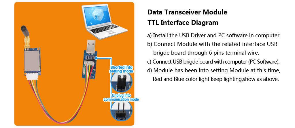
6 After powered on reset, the TX LED (Red) and RX LED (Blue) will blink 3 times, The total reset time is arround 2s, as below: Note:Contact us to customize if you want to shorten the POR time. Working mode The CS and SET Pin is internally pulled up. Pull CS pin high or leave it open will make modules enter into working mode, the serial and RF are both in receiving mode then. In NODE working mode, SV-MESH module stay in receiving mode and wait for the series signal and RF signal. SV-MESH module can connect with any device which is standard 232/485/TTL interface. When series signal comes, SV-MESH module will check the input series signal if there is any error, and then transmit the received data out via RF automatically if no errors found. When RF signal comes, SV-MESH module will check the input RF signals if there is any error, and then transmit the received data out via series port automatically if no errors found. When one packet is transmitted successfully, the Red LED will blink once. When one packet is received and verified with no problem, the Blue LED will blink once. The easiest way to test the module is using computer. The corresponding PC software is Series Debugging assistant can be downloaded at : the password for download is nicerf. User can use our USB bridge board (SU108 TTL / SU /SU ) to connect SV-MESH module with computer. The GUI of the software is as below: SV-MESH module transmit the data transparently. In one side, signal input to the transmitter, in other side ( receiver ), the signal will be output same as the input. The signal is encrypted to guarantee the safety during the transmission. Serial port or computer with USB bridge board can be used to input signal to the module. Below is the GUI for data transmission and reception. TEL: FAX: sales@nicerf.com 第 6 页共 29 页


7 To ensure the stability of communication, please notice the following tips: 1) Parameter matching The series parameter between the device and MESH module should be same, frequencies, channels, NET ID and RF parameters should be same in Tx and Rx. Note: Default setting is: Baud rate=9600bps,data bit=8,stop bit: 1,parity bit: none 2) Delay Time Data delay is exist between series input of the transmitter and series output of the receiver. This Delay Time is different from the series data rate, RF data rate and payload length. Detailed value is as below: Speed rate byte transceiver time(ms) TEL: FAX: 第 7 页共 29 页

8 56bytes transceiver time(ms) 3) Package transmission One packet can not exceed 56 bytes. SV-mesh can t work when the payload length exceed 56bytes. Router mode When set as ROUTER, in working mode, SV-MESH module can repeat the RF signal in the same network automatically to extend the distance. Normally, Router module is connected with external power supply to keep long time in receiving mode and repeat the signal to extend the range. To ensure the stability and correctness of communication, please notice the following tips: 1) To ensure the normal working of ROUTER, the node should send the data with minimal time interval between adjacent packets. The time interval is different from the data length, RF data rate and TEL: FAX: sales@nicerf.com 第 8 页共 29 页


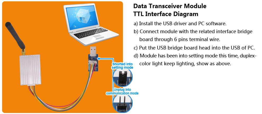
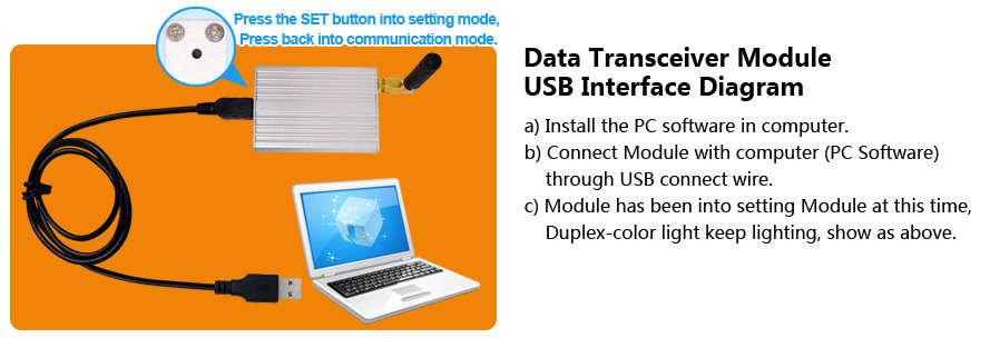
9 baud rate. When RF data rate is the same as baud rate, and the data length is 56bytes, the minimal time interval as below: Rate Time(ms) Setting Mode In working mode, pull low the SET pin to force SV-MESH module into setting mode. When using USB bridge board, simply put on the short cap to enter into setting mode. In setting mode, both blue and red LED will light on, shown as below: TEL: FAX: 第 9 页共 29 页
10 TEL: FAX: 第 10 页共 29 页


11 In setting mode, users can set the parameters by PC software or customer s own device. The parameters will be stored and keep unchanged even powered off. Step to set the module with PC: Download the PC software at: ******, the password is nicerf. Download the USB driver at: the password is nicerf. Install the PC software and USB driver into computer. Connect RF module with USB Bridge, put on the short cap, and insert into the PC. Open the PC software, the GUI is as below: Select the right COM port and click OPEN button, all the parameters stored in the module will be read out and display, the status bar will appear the message Device Found. If SV-MESH module hasn t connected with PC correctly or wrong COM port is chosen, the status bar will show Device Not Found. TEL: FAX: sales@nicerf.com 第 11 页共 29 页

12 Note: About the Net ID and Node ID After connected with PC correctly, all the parameters can be set freely including Net ID and Node ID. The Net ID is the group name for transmitter and receiver, all the transmitter and receiver with the same Net ID can communicate with each other. The only exception is When the Net ID is set as 0000, it can receive the signal of all the transmitter even the Net ID is not The Node ID can be thought as the name of the module. Each module can be set with one Node ID. The Node can set and read out freely. The Node ID can be used in the application which the receiver should identify who is the transmitter. User can read out the Node ID of the module, and add the Node ID into the payload, then in Rx side, it can identify who is the transmitter. Communication Protocol: TEL: FAX: 第 12 页共 29 页
13 Besides PC, user can set all the parameters by their own device. The communication protocol is as below: Baud rate=9600 bps; Data bit=8 bits Stop bit:1 Parity bit: none Command format:aa FA + command + [parameter] Command is 1bit,parameter is 0 or 14bytes in HEX format. Return value ended with \r\n. a) Command[AA]: Read module name and version Instruction: AA FA AA Return: SVxxx_Verx.x \r\n. b) Command [01]: Read out all the parameters Instruction format: AA FA 01 The return value in turn is: RF channel / RF band / RF data rate / RF power / Serial data rate / Series Data bit / Series Stop bit / Series Parity bit / NET ID / NODE ID /\r\n For example, when module is default setting, the return are as below: c) Command[02]: Reset to default setting Instruction format: AA FA 02 The return value in turn is: "OK \ r \ n" or "ERROR \ r \ n" After this command, the module will reset to default setting,which is Frequency : Tx = Rx = CH20 = MHz (Band = 433MHz) RF data rate: Tx = Rx=9600 bps RF power= 7 (Max output) Serial: baud rate = 9600 bps Data bit= 8 Bits Stop bit = 1 Bits Parity bit=none NET ID = NODE ID = d) Command[03]: Set the group parameters The Parameters Length of the command is 17 bytes, and format as follows: TEL: FAX: sales@nicerf.com 第 13 页共 29 页
 RF Channel = RF Frequency Each frequency band is divided into 40 channels; user can select one of the 40 channels to use.")
14 Instruction format: AA FA 03 RF Channel / RF Band / RF Rate / RF Power / Serial transmission date / data bits / stop bits / parity / NET ID / NODE ID The return is: "OK \ r \ n" or "ERROR \ r \ n Parameters Description: 1) RF Channel = RF Frequency Each frequency band is divided into 40 channels; user can select one of the 40 channels to use. The interval is 1MHz between two adjacent frequencies,corresponding frequency is as below: 2) Working Band: The working band is as below: TEL: FAX: sales@nicerf.com 第 14 页共 29 页
15 Parameter Frequency 433 MHz 470 MHz 868 MHz 915 MHz ~ ~ ~ ~ Note:Changing working band is not suggested. 3) RF data rate: The RF data rate is as below Parameter TX/RX rate(bps) ) RF output power: Range: 0-7 levels, The maximum output power is different from different type of module. The output power is as below: Set level TX/RX power dbm dbm dbm dbm dbm dbm dbm dbm 5) Serial baud rate Series data rate is as below: Parameter Serial rate(bps) ) Serial data bit Series data bit is as below: Parameter Data Bits 7 bits 8 bits 9 bits 7) Serial stop bit Series stop bit is as below: Parameter 1 2 TEL: FAX: sales@nicerf.com 第 15 页共 29 页
16 Stop bit 1 bits 2 bits 8) Serial parity Series Parity bit is as below: Parameter Parity bit No Odd Even 9) NET ID:The Net ID is 4 bytes, and range from to FF FF FF FF Note: if the modules NET ID setting are different, then they can't communicate with each other except when the Net ID = 0000, it will receive all the message despite the Net ID is difference. 10) NODE ID:Read only value The Node ID is 2 bytes, range from to FF FF. 11)Mode: Set as Node when it connected with device to get data,others set as Router. Parameter 0 1 Mode NODE Router Sleep mode After Power on Reset, the module enters into sleep mode when CS pin is pulled low. In this mode, the current consumption is very small. In Sleep mode, the module can t do any communication and cant be set even Set Pin is pulled low. All the parameters will be kept unchanged in Sleep mode. User can wake up the module by pulling high the CS Pin. RSSI index The RSSI index value can only be read out in setting mode. The real time RSSI index is updated by incoming signal. Instructions format: AA FA 04 Return:RSSI index\00\r\n (hexadecimal,range:0x00~0xff) RSSI index range: 00 ~ FFh For example: Instruction format: AA FA 04 TEL: FAX: sales@nicerf.com 第 16 页共 29 页
When worked with TTL or RS232 interface, the serial port of modules should cross match with the serial port of customer s")
17 Return:32 00 \r\n.(signal stength is 0x32) Relationship between RSSI and input power is as below 7. Typical connections: The typical schematic circuit is as below: Note: 1)When worked with TTL or RS232 interface, the serial port of modules should cross match with the serial port of customer s device(txd(a+) to RXD, RXD(B-) to TXD). 2)For RS485 interface, the serial port of module match the serial port of customer s device(a to A, B to B) 3)The ground pin of the module and device should be connected together TEL: FAX: sales@nicerf.com 第 17 页共 29 页
 2 GND Connected to ground 3 TXD TXD of the module and connect to external RXD 4 RXD RXD of the module and connect to")
18 Typical connection as below: 8. Pin Definition: 610 Pin No. Definition Description 1 VCC Connected to the positive power supply (typical 5V) 2 GND Connected to ground 3 TXD TXD of the module and connect to external RXD 4 RXD RXD of the module and connect to external TXD 5 SET 6 CS 7 GND Connected to ground Configuration mode enable (low to enter into the setting mode, leave open or connect high level to exit setting mode) Valid when CS Pin is high or leave open. Module working Enable(Pull Low to make the module enter into sleep mode, Leave open or connect high level make the module enter into normal working mode) 8 ANT Connected with antenna(50ohm copper coaxial antenna) TEL: FAX: sales@nicerf.com 第 18 页共 29 页
19 650: Pin No. Definition Description Configuration mode enable (low to enter into the setting mode, leave 1 SET 2 CS open or connect high level to exit setting mode) Valid when CS Pin is high or leave open. Module working Enable(Pull Low to make the module enter into sleep mode, Leave open or connect high level make the module enter into normal working mode) 3 TXLED LED Indicator for transmission(active when low level) 4 RXLED LED Indicator for reception(active when low level) NC null GND Connected to ground 9 ANT Connected with antenna(50ohm copper coaxial antenna) 14 VCC Connected to the positive power supply (typical 5V) 15 RXD/B 16 TXD/A RXD of the module and connect to external TXD (@485 level, connect with B to output ) TXD of the module and connect to external RXD (@485 level, connect with A to output) series: TEL: FAX: sales@nicerf.com 第 19 页共 29 页
20 Pin No. Definition Description SV-MESH Mesh network series 1 VCC Connected to the positive power supply (typical 5V) 2 GND Connected to ground 3 TXD/A 4 RXD/B TXD of the module and connect to external RXD (@485 level, connect with A to output) RXD of the module and connect to external TXD (@485 level, connect with B to output ) Configuration mode enable (low to enter into the setting mode, 5 SET leave open or connect high level to exit setting mode) Valid when CS Pin is high or leave open. 6 CS Module working Enable(Pull Low to make the module enter into sleep mode, Leave open or connect high level make the module enter into normal working mode) series: Pin No. Definition Description 1 VCC Connected to the positive power supply (typical 5V) 2 GND Connected to ground 3 TXD/A 4 RXD/B 5 SET 6 CS TXD of the module and connect to external RXD (@485 level, connect with A to output) RXD of the module and connect to external TXD (@485 level, connect with B to output ) Configuration mode enable (low to enter into the setting mode, leave open or connect high level to exit setting mode) Valid when CS Pin is high or leave open. Module working Enable(Pull Low to make the module enter into sleep mode, Leave open or connect high level make the module enter into normal working mode) series: TEL: FAX: sales@nicerf.com 第 20 页共 29 页

21 series: series: TEL: FAX: 第 21 页共 29 页
 5")
22 Pin No. Definition Description 1 TXD TXD of the module and connect to external RXD 2 RXD RXD of the module and connect to external TXD 3 GND Connected to ground 4 A + Serial communication TXD (RS485 Level) 5 B - Serial communication RXD ( RS485 Level) Configuration mode enable (low to enter into the setting mode, leave open or 6 SET 7 CS connect high level to exit setting mode) Valid when CS Pin is high or leave open. Module working Enable(Pull Low to make the module enter into sleep mode, Leave open or connect high level make the module enter into normal working mode) 9. Accessories: 1. Antenna antenna is very important for RF communication, its performance will affect the communication directly. Module needs antenna in 50ohm. Common antenna has rubber straight/ elbow/ foldable rod and sucker antenna and etc. Users can order accordingly. To ensure module in the best performance, we suggest to use the our antenna TEL: FAX: sales@nicerf.com 第 22 页共 29 页


23 To ensure modules get the best performance, user must obey the following principles when using the antennas: Put the antenna away from the ground and obstacles as possible as you could; If you choose the sucker antenna, pull straight the lead wire as possible as it can be, the sucker under arches should be attached on the metal object. 2. USB bridge board There are 3 type of USB bridge, which is SU108-TTL/ SU / SU SU108 -TTL is for TTL Interface, SU is for 232 Interface, SU is for 485 Interface. User should select the right USB bridge corresponding to the RF module. Note: If the output power of module is 2W or higher, it require external power supply when the modules working. TEL: FAX: sales@nicerf.com 第 23 页共 29 页
24 10. Mechanical Dimensions: 610 Dimensions: 611 Dimensions: TEL: FAX: 第 24 页共 29 页
25 650 Dimensions: 651 Dimensions: TEL: FAX: 第 25 页共 29 页
26 Dimensions: Dimensions: TEL: FAX: 第 26 页共 29 页
27 11. Order information: For example: If the customer needs 5W 433MHz band with TTL port, then the part number of released order shall be: SV6500-MESH-TTL-433 SV-MESH series: Note: SV-MESH series are same as our SV series modules in hardware. It has different output power and different interface for option. Product Name Power Interface Picture SV610-MESH 100mW TTL SV611-MESH 100mW TTL/RS232/RS485 SV612-MESH 100mW TTL/RS232/RS485 TEL: FAX: 第 27 页共 29 页
28 SV613-MESH 100mW USB SV-MESH Mesh network series SV614-MESH 100mW RS232 SV650-MESH 500mW TTL /RS485 SV651-MESH 500mW TTL/RS232/RS485 SV652-MESH 500mW TTL/RS232/RS485 SV653-MESH 500mW USB SV654-MESH 500mW RS232 SV6202-MESH 2W TTL/RS232/RS485 SV6300-MESH 3W TTL/RS232/RS485 SV6500-MESH 5W TTL/RS232/RS FAQ: A. Why module can not communicate properly? 1) Check if there is power connection error; 2) Check if the module is enabled (CS / SET both high); 3) Check if the band, channel, rate, NET ID has set to the same; 4) Check if the module is damaged(light is on?) TEL: FAX: sales@nicerf.com 第 28 页共 29 页
29 B. Why transmission distance is not far as it should be? SV-MESH Mesh network series 1) Power supply ripple is too large; 2) The antenna types do not match, or not properly installed; 3) The surrounding environment is harsh, strong interference sources; 4) Surrounding co-channel interference; C. Why receiving data incorrect? 1) Check if the interface compatible with the device; 2) Improper parameter settings. 3) Module data interface is bad. TEL: FAX: 第 29 页共 29 页
Catalogue
 - 1 - Catalogue 1. Description... - 3-2. Features... - 3-3. Applications...- 3-4. Block Diagram... - 3-5. Electrical Characteristics...- 4-6. Operation...- 5 - Power on Reset... - 5 - Working mode... -
Catalog
 - 1 - Catalog 1. Description...- 3-2. Features...- 3-3. Applications... - 3-4. Block Diagram...- 3-5. Electrical Characteristics... - 5-6. Operation... - 5 - Power on Reset... - 5 - Working mode... - 6
Catalog
 - 1 - Catalog 1. Overview... - 3-2. Feature...- 3-3. Application... - 3-4. Block Diagram... - 3-5. Electrical Characteristics...- 4-6. Operation...- 4-1) Power on Reset... - 4-2) Sleep mode...- 4-3) Working
Catalog
 - 1 - Catalog 1. Overview...- 3-2. Feature... - 3-3. Application...- 3-4. Block Diagram...- 3-5. Electrical Characteristics... - 4-6. Operation... - 4-1) Power on Reset... - 4-2) Sleep mode... - 4-3) Working
Embedded Radio Data Transceiver SV611
 Embedded Radio Data Transceiver SV611 Description SV611 is highly integrated, multi-ports radio data transceiver module. It adopts high performance Silicon Lab Si4432 RF chip. Si4432 has low reception
USB Port Medium Power Wireless Module SV653
 USB Port Medium Power Wireless Module SV653 Description SV653 is a high-power USB interface integrated wireless data transmission module, using high-performance Silicon Lab Si4432 RF chip. Low receiver
SV613 USB Interface Wireless Module SV613
 USB Interface Wireless Module SV613 1. Description SV613 is highly-integrated RF module, which adopts high performance Si4432 from Silicon Labs. It comes with USB Interface. SV613 has high sensitivity
LoRa1276 Catalogue
 Catalogue 1. Overview... 3 2. Features... 3 3. Applications... 3 4. Electrical Characteristics... 4 5. Schematic... 5 6. Speed rate correlation table... 6 7. Pin definition... 6 8. Accessories... 8 9.
RF4432F27 Catalog
 Catalog 1. Description... 3 2. Features... 3 3. Application... 3 4. Electrical Specifications... 4 5. Typical application circuit... 4 6. Pin definition... 5 7. Accessories... 6 8. Mechanical dimension...
RF1212 Catalog
 Catalog 1. Description... 3 2. Features... 3 3. Application... 3 4. Typical application circuit... 4 5. Electrical Specifications... 4 6. Pin definition... 5 7. Accessories... 5 8. Mechanical dimension...
Catalogue
 Catalogue 1. Overview... - 3-2. Features... - 3-3. Applications...- 3-4. Electrical Characteristics...- 4-5. Schematic... - 4-6. Speed rate correlation table...- 6-7. Pin definition...- 6-8. Accessories...-
Catalogue
 Catalogue 1. Overview... - 3-2. Features... - 3-3. Applications...- 3-4. Electrical Characteristics...- 4-5. Schematic... - 5-6. Speed rate correlation table...- 5-7. Pin definition...- 6-8. Accessories...-
RF NiceRF Wireless Technology Co., Ltd. Rev
 - 1 - Catalog 1. Description...- 3-2. Features...- 3-3. Application...- 3-4. Electrical Specifications...- 4-5. Schematic...- 4-6. Pin Configuration...- 5-7. Antenna... - 6-8. Mechanical dimensions(unit:
LORA1276F30 Catalogue
 Catalogue 1. Overview... 3 2. Feature... 3 3. Application... 3 4. Block Diagram... 4 5. Electrical Characteristics... 4 6. Schematic... 5 7. Speed rate correlation table... 6 8. Pin definition... 6 9.
Catalog
 Catalog 1. Description... - 3-2. Features... - 3-3. Application... - 3-4. Electrical specifications...- 4-5. Schematic... - 4-6. Pin Configuration... - 5-7. Antenna... - 6-8. Mechanical Dimension(Unit:
LORA1278F30 Catalogue
 Catalogue 1. Overview... 3 2. Feature... 3 3. Application... 3 4. Block Diagram... 4 5. Electrical Characteristics... 4 6. Schematic... 5 7. Speed rate correlation table... 6 8. Pin definition... 6 9.
RF4463F30 High Power wireless transceiver module
 RF4463F30 High Power wireless transceiver module 1. Description RF4463F30 adopts Silicon Lab Si4463 RF chip, which is a highly integrated wireless ISM band transceiver chip. Extremely high receive sensitivity
Catalog
 - 1 - Catalog 1. Description...- 3-2. Features...- 3-3. Application...- 3-4. Block Diagram...- 3-5. Electrical Characteristics... - 4-6. Operation... - 4-1) Power on Reset...- 4-2) Setting Mode... - 5-3)
RF4432PRO wireless transceiver module
 wireless transceiver module RF4432PRO 1. Description RF4432PRO adopts Silicon Lab Si4432 RF chip, which is a highly integrated wireless ISM band transceiver chip. Extremely high receive sensitivity (-121
Four channel wireless switch controller SK108
 Four channel wireless switch controller SK108 Description SK108 is a industrial four channel wireless switch controller, it provides maximum four channel signal input and maximum four channel control output.
RF ISM Transparent Transceiver Module V4.0
 RF7020-27 ISM Transparent Transceiver Module V4.0 Overview: RF7020-27 is highly integrated semi-duplex medium power transceiver module with high speed MCU and high performance RF IC. Utilizing high efficiency
RF4432 wireless transceiver module
 1. Description www.nicerf.com RF4432 RF4432 wireless transceiver module RF4432 adopts Silicon Lab Si4432 RF chip, which is a highly integrated wireless ISM band transceiver. The features of high sensitivity
RF7129 Ultra-low power Tranceiver module V2.0
 1. General RF7129 series is a low cost, ultra-low power, high performance transparent two way semi-duplex GFSK transceiver with operation at 433/470/868/915 Mhz. It integrates with high speed MCU from
Catalog
 - 1 - Catalog 1. Description... - 3-2. Features... - 3-3. Application... - 3-4. Schematic... - 3-5. Electrical Specifications...- 4-6. Pin Definition... - 4-7. Antenna... - 5-8. Mechanical Dimension...-
RF1212 RF1212 Ultra-low Power ISM Transceiver Module V2.0
 RF1212 Ultra-low Power ISM Transceiver Module V2.0 Application: Features: Home automation Security alarm Telemetry Automatic meter reading Contactless access Wireless data logger Remote motor control Wireless
RF1276 Long Distance Transceiver module V2.0
 1. General RF1276 series is a low cost, ultra-low power, high performance transparent two way semi-duplex LoRa modulation transceiver with operation at 169/433/868/915 Mhz. It integrates with high speed
HC-12 Wireless Serial Port Communication Module
 HC-12 Wireless Serial Port Communication Module User Manual version 2.3C (updated from v1.1 English and v2.3 Chinese) Product Applications Wireless sensor Community building security Robot wireless control
JZ878 RF Data Radio. User s Manual
 JZ878 RF Data Radio User s Manual SHEN JIZHUO TECHNOLOGY CO., LTD TEL: +86-755-83304518 / 83308451/81353151 FAX: +86-755-83302824 Address: NO.813,212BLD,Tairan Tech Park, Futian District Shenzhen China
E31-TTL-500 Datasheet V Feature E31-TTL-500
 E31-TTL-500 Datasheet V1.0.1.Introduction E31-TTL-500 1.1 Feature E31-TTL-500 E31-TTL-500 is a 500mW wireless transceiver module with narrow-band transmission, operates at 425-450.5MHz (default: 433MHz),
SA818 Catalogue
 Catalogue 1. Descriptions... 3 2. Features... 3 3. Application... 3 4. Internal block diagram... 3 5. Specification... 4 6. Typical Application Schematic... 4 7. Pinout definition... 5 8. Mechanism Dimension...
Low Power with Long Range RF Module DATASHEET Description
 Wireless-Tag WT-900M Low Power with Long Range RF Module DATASHEET Description WT-900M is a highly integrated low-power half-'duplex RF transceiver module embedding high-speed low-power MCU and high-performance
G3P-R232. User Manual. Release. 2.06
 G3P-R232 User Manual Release. 2.06 1 INDEX 1. RELEASE HISTORY... 3 1.1. Release 1.01... 3 1.2. Release 2.01... 3 1.3. Release 2.02... 3 1.4. Release 2.03... 3 1.5. Release 2.04... 3 1.6. Release 2.05...
SMARTALPHA RF TRANSCEIVER
 SMARTALPHA RF TRANSCEIVER Intelligent RF Modem Module RF Data Rates to 19200bps Up to 300 metres Range Programmable to 433, 868, or 915MHz Selectable Narrowband RF Channels Crystal Controlled RF Design
LoRa1278 Wireless Transceiver Module
 LoRa1278 Wireless Transceiver Module 1. Description LoRa1278 adopts Semtech RF transceiver chip SX1278, which adopts LoRa TM Spread Spectrum modulation frequency hopping technique. The features of long
DRF4432D20 20dBm ISM RF Transceiver Module V1.21
 DRF4432D dbm ISM RF Transceiver Module V1.21 Features GFSK transceiver Module ISM frequency bands 19.2K bps data rate Multiple channels dbm Max. output power Baud rate configurable 256 bytes data buffer
Purchase the sample: E51-TTL-500 Datasheet V Feature E51-TTL-500
 E51-TTL-500 Datasheet V1.0.1.Introduction E51-TTL-500 1.1 Feature E51-TTL-500 E51-TTL-500 is a 500mW wireless transceiver module(uart), with transparent transmission, operates at 225-237.6MHz z(default
AT-XTR-7020A-4. Multi-Channel Micro Embedded Transceiver Module. Features. Typical Applications
 AT-XTR-7020A-4 Multi-Channel Micro Embedded Transceiver Module The AT-XTR-7020A-4 radio data transceiver represents a simple and economical solution to wireless data communications. The employment of an
DRF4463D20 Medium Power ISM RF Transceiver Module V1.21
 DRF4463D20 Medium Power ISM RF Transceiver Module V1.21 Features GFSK transceiver Module 433Mhz ISM frequency band 40Kbps RF data rate Multiple channels 20dBm Max. output power -121dBm sensitivity @1k
DMR818 Catalogue
 Catalogue 1. Descriptions... 3 2. Features... 3 3. Application... 4 4. Block Diagram... 4 5. Electrical Characteristics... 4 6. Typical Schematic Circuit:... 5 7. Functions descriptions:... 5 1) Voice
KAPPA M. Radio Modem Module. Features. Applications
 KAPPA M Radio Modem Module Features Intelligent RF modem module Serial data interface with handshake Host data rates up to 57,600 baud RF Data Rates to 115Kbps Range up to 500m Minimal external components
SRX882
 Catalog 1. Overview... 2 2. Features... 2 3. Application... 2 4. Electronic Specifications... 3 5. Pin difinition... 3 6. Mechnical dimension... 4 7. Appendix... 4 7.1. Features... 4 7.2. Structure explanation...
TRANSCEIVER FSK. Version: 434 MHz Band / 868 MHZ Band / Code: / A
 TRANSCEIVER FSK Version: 434 MHz Band / 868 MHZ Band / Code: 3-2000519 / 3-2000519A DESCRIPTION: The 3-2000519 and 3-2000519A modules are fully programmable multichannel PLL based FSK transceivers, with
DRF7020D13 13dBm ISM RF Transceiver Module
 3dBm ISM RF Transceiver Module V2.2 Features Application GFSK transceiver Module 433Mhz ISM frequency band 9.6K bps FSK data rate Multiple channels 3dBm Max. output power Baud rate configurable 256 bytes
Applications. Operating Modes. Description. Part Number Description Package. Many to one. One to one Broadcast One to many
 RXQ2 - XXX GFSK MULTICHANNEL RADIO TRANSCEIVER Intelligent modem Transceiver Data Rates to 100 kbps Selectable Narrowband Channels Crystal controlled design Supply Voltage 3.3V Serial Data Interface with
E70-433MS14 Datasheet v1.1
 E70-433MS14 Datasheet v1.1 Contents 1. Introduction... 2 2. Features... 3 3. E70 Series... 3 4. Electrical Parameter... 4 5. UART Functional description (default)... 5 5.1 Fixed transmission... 5 5.2 Broadcast
RF-TTL-100 Datasheet. 1. Introduce. 2. Parametric Description. 4. Application. 3. Module Features
 1. Introduce RF-TTL-100 is our latest 100mW wireless transmission module. It working in 148-173.5MHz band and using serial port to send or receive data. Its advantage is that centralized power density,
DRF7020D20 20dBm ISM RF Transceiver Module V1.31
 DRF7020D20 20dBm ISM RF Transceiver Module V1.31 Features GFSK transceiver Module 433Mhz ISM frequency band 19.2K bps data rate Multiple channels 20dBm Max. output power Baud rate configurable 256 bytes
DUAL BAND FM WIRELESS TRANSCEIVER RXQ1. Applications
 FM Radio Transmitter & Receiver Low Profile Ceramic DIL Package Data Rates To 20 Kbits/S 433.92 or 433.33MHz Operation 2 Selectable Channels Narrowband Crystal Controlled Optimal Range 200m Supply Voltage
DRF5150S Wireless Sensor Transmitter Module V1.30
 DRF5150S Wireless Sensor Transmitter Module V1.30 Features GFSK Transmitter module ISM frequency bands 81K bps data rate 10dBm output power Baud rate configurable 256 bytes data buffer Standby current
HC SI4463 Wireless Serial Module
 HC-12 433 SI4463 Wireless Serial Module Description: HC-12 wireless serial port communication module is a new-generation multichannel embedded wireless data transmission module. Its wireless working frequency
AcuMesh Wireless RS485 Network. User's Manual SOLUTION
 AcuMesh Wireless RS485 Network User's Manual AN SOLUTION ACUMESH - WIRELESS METERING SYSTEM COPYRIGHT 2015 V1.2 This manual may not be altered or reproduced in whole or in part by any means without the
VT-DTMSA5-433M RF Transceiver Module User s guide
 RF Transceiver Module User s guide V-Chip Microsystems, Inc Add:6 floor, Longtang Building, Nan Shan Cloud Valley Innovation Industrial Park, No.1183, Liuxian Road, Nanshan District, Shenzhen city Tel:86-755-88844812
E45-TTL-100 Datasheet v1.2
 E45-TTL-100 Datasheet v1.2 Contents 1. Introduction... 2 1.1 Feature... 2 1.2 Electrical parameter...3 1.3 E45 Series...3 2. UART functional description (default)...4 2.1 Fixed transmission...4 2.2 Broadcast
Catalogue
 - 1 - Catalogue 1. Description...- 3-2. Features...- 3-3. Application...- 3-4. Block Diagram...- 4-5. Typical Schematic Circuit...- 4-6. Electrical Characteristics... - 5-7. Interface specification...-
Catalogue 1. Brief Description Product feature Typ. Circuit Block Diagram...
 - 1 - Catalogue 1. Brief Description... - 3-2. Product feature...- 3-3. Typ. Circuit... - 4-4. Block Diagram...- 4-5. Electronical Characters...- 5-6. Typical Application...- 6-7. Pin Description... -
C Mono Camera Module with UART Interface. User Manual
 C328-7221 Mono Camera Module with UART Interface User Manual Release Note: 1. 16 Mar, 2009 official released v1.0 C328-7221 Mono Camera Module 1 V1.0 General Description The C328-7221 is VGA camera module
FC-201/SA Micropower Audio/Data RF Module(433MHz)
") FC-201/SA Micropower Audio/Data RF Module(433MHz) USER MANUAL SHENZHEN FRIENDCOM TECHNOLOGY DEVELOPMENT CO.,LTD Address: 2/F, Multifunction Building, Dongpeng Industrial Park, Wuhao Road, North Section
FC-201/SA Micropower Audio/Data RF Module(433MHz) USER MANUAL SHENZHEN FRIENDCOM TECHNOLOGY DEVELOPMENT CO.,LTD Address: 2/F, Multifunction Building, Dongpeng Industrial Park, Wuhao Road, North Section
Purchase the sample:http://www.aliexpress.com/store/ E32-TTL-100 Datasheet V Feature E32-TTL-100
 E32-TTL-100 Datasheet V1.0.1.Introduction E32-TTL-100 1.1 Feature E32-TTL-100 E32-TTL-100 is a wireless transceiver module with LoRa spread-spectrum technology, operates at 434MHz, based on original imported
USB-UART RADIO MODULE(WM11TR_ L_02_USB)
") Documents Version: 2.05 Document No. 2012-0046-E Copyright is reserved by Rping Group Limited (2008-2015) USB-UART RADIO MODULE(WM11TR_ L_02_USB) USER GUIDE 82469790 Index Documents Version: 2.05... 1
Documents Version: 2.05 Document No. 2012-0046-E Copyright is reserved by Rping Group Limited (2008-2015) USB-UART RADIO MODULE(WM11TR_ L_02_USB) USER GUIDE 82469790 Index Documents Version: 2.05... 1
WIRELESS NETWORK USER MANUAL MHz RFT-868-REL Remotely Controlled Relay Switch
 WIRELESS NETWORK USER MANUAL 868.3 MHz Remotely Controlled Relay Switch Device Specifications Max Switching Voltage: 250 VAC Max Switching Current: 10 A Max Switching Power: 2500 VA Power Draw in standby
SRWF-1022 Series Low Power Wireless Transceiver Module User Manual
 SRWF-1022 Series Low Power Wireless Transceiver Module User Manual Page 1 of 6 I. SRWF-1022 SRWF-1022 User Manual (V1.1) SRWF-1022, the low-power wireless transceiver module is used as the wireless command
SmartRadio Transmitter / Receiver
 Easy to use Radio Transmitter & Receivers AM Radio Hybrid Technology Supports Data or Telemetry communications Simple CMOS/TTL Data Interface Automatic data encryption / decryption Host Interface up to
VT-CC M Wireless Module. User Guide
 Wireless Module User Guide V-CHIP MICROSYSTEMS Co. Ltd Address: Room 612-613, Science and Technology Service Center Building, NO.1, Qilin Road, Nanshan District, Shenzhen, Guangdong TEL:0755-88844812 FAX:0755-22643680
RM24100D. Introduction. 1 Features. 2.4GHz 100mW RS232 / RS485 / RS422 DSSS Radio Modem (IEEE compliant) Operating Manual English 1.
 Operating Manual English 1.") RM24100D 2.4GHz 100mW RS232 / RS485 / RS422 DSSS Radio Modem (IEEE 802.15.4 compliant) Operating Manual English 1.03 Introduction The RM24100D radio modem acts as a wireless serial cable replacement and
RM24100D 2.4GHz 100mW RS232 / RS485 / RS422 DSSS Radio Modem (IEEE 802.15.4 compliant) Operating Manual English 1.03 Introduction The RM24100D radio modem acts as a wireless serial cable replacement and
FC-703C Wireless M-bus Module DATA SHEET
 FC-703C Wireless M-bus Module DATA SHEET FRIENDCOM TECHNOLOGY DEVELOPMENT CO.,LTD Address: Comprehensive building, Wanyelong science and technology Park, Liyuan Industrial Zone, Shiyan Street, Bao'an District,
TRXQ1 RXQ1 FM NARROW BAND TRANSCEIVERS. RXQ1 Version. Applications. TRXQ1 Version
 RF Transceiver or Intelligent Modem Versions Host Data Rate upto 19,200 Baud Data Rates to 20 K baud. 2 Selectable RF Channels Narrowband Crystal Controlled Optimal Range 200m Supply Voltage 3-5V Very
RM24100A. Introduction. 1 Features. 2.4GHz 100mW RS232 / RS485 / RS422 DSSS Radio Modem (IEEE compliant) Operating Manual English 1.
 Operating Manual English 1.") RM24100A 2.4GHz 100mW RS232 / RS485 / RS422 DSSS Radio Modem (IEEE 802.15.4 compliant) Operating Manual English 1.03 Introduction The RM24100A radio modem acts as a wireless serial cable replacement and
RM24100A 2.4GHz 100mW RS232 / RS485 / RS422 DSSS Radio Modem (IEEE 802.15.4 compliant) Operating Manual English 1.03 Introduction The RM24100A radio modem acts as a wireless serial cable replacement and
Product Specifications. Wireless Communication Module
 Product Specifications LoRa Wireless Communication Module LM-110H1 VER 1.0 GlobalSat WorldCom Corporation 16F., No. 186, Jian 1 st Rd, Zhonghe Dist., New Taipei City 23553, Taiwan Tel: 886.2.8226.3799/
SA828. SA828 All-in-One walkie-talkie module Description. SA828-U: U band, MHz SA828-V: V band, MHz
 www.nicerf.com 1. Description All-in-One walkie-talkie module is an all-in-one professional walkie-talkie module in small size. It is very easy to use with powerful function. This module has full function
Catalogue
 - 1 - Catalogue 1. Descriptions...- 3-2. Features... - 3-3. Application...- 4-4. Block Diagram... - 4-5. Electrical Characteristics...- 4-6. Typical Schematic Circuit:...- 5-7. Functions descriptions:...-
Multi-Channel RS-232 Serial RF Transceiver
 RF-232 Multi-Channel RS-232 Serial RF Transceiver The RF-232 subassembly is a multi-channel serial radio transceiver. This device accepts and outputs standard serial data at one of three selectable data
DRF4431F27 27dBm ISM RF Transceiver Module V1.10
 27dBm ISM RF Transceiver Module V1.10 Features: Frequency Range: 433/868MHz Modulation: FSK/GFSK/OOK SPI Data Interface Sensitivity: -122dBm Output Power: +27dBm Data Rate: -0.123~256 kbps Digital RSSI
Arduino Arduino RF Shield. Zulu 2km Radio Link.
 Arduino Arduino RF Shield RF Zulu 2km Radio Link Features RF serial Data upto 2KM Range Serial Data Interface with Handshake Host Data Rates up to 38,400 Baud RF Data Rates to 56Kbps 5 User Selectable
HAC-UT V6.3 Wireless Single Meter/Double pipe Metering type Wireless Transmitter. HAC-LMR Wireless Data Receiver/ Repeater Module
 HAC-UT V6.3 Wireless Single Meter/Double pipe Metering type Wireless Transmitter HAC-LMR Wireless Data Receiver/ Repeater Module SHENZHEN HAC TELECOM TECHNOLOGY CO., LTD Address: 3rd Area, 19 th Fl, Tower
DRF1278F 20dBm LoRa Long Range RF Front-end Module V1.11
 20dBm LoRa Long Range RF Front-end Module V1.11 Features: Frequency Range: 433MHz Modulation: FSK/GFSK/MSK/LoRa SPI Data Interface Sensitivity: -139dBm Output Power: +20dBm Data Rate:
VT-CC1110PA-433M. Wireless Module. User Guide
 Wireless Module User Guide V-Chip Microsystems, Inc Add:6 floor, Longtang Building, Nan Shan Cloud Valley Innovation Industrial Park, No.1183, Liuxian Road, Nanshan District, Shenzhen city Tel:86-755-88844812
Radio Module for MHz. Band RMCx4-1 ; RMCx9-1
 General Information The Radio Modules RMCx 4-1 and RMCx 9-1 are transceivers designed for very low power and very low voltage wireless applications. The circuit is mainly intended for the ISM (Industrial,
SRWF-1021 Series Low Power Wireless Transceiver Data Module User Manual
 SRWF-1021 Series Low Power Wireless Transceiver Data Module User Manual Page 1 of 11 SRWF-1021 User Manual (V1.3) I. SRWF-1021 Main Application Range SRWF-1021, the low-power wireless transceiver data
Revision WI.232FHSS-25-FCC-R and RK-WI.232FHSS-25-FCC-R USER S MANUAL
 Revision 1.0.3 WI.232FHSS-25-FCC-R and RK-WI.232FHSS-25-FCC-R USER S MANUAL RADIOTRONIX, INC. WI.232FHSS-25-FCC-R/ RK-WI.232FHSS-25-FCC-R USER S MANUAL Radiotronix 905 Messenger Lane Moore, Oklahoma 73160
HM-TRP Series 100mW Transceiver modules V1.0
 1. General HM-TRP series is a low cost, high performance transparent FSK transceiver with operating at 434/47O/869/915 MHz. It features small size, high output power, high sensitivity, long transmission
HM-TRP Series. 100mW Transceiver Modules V General. 2. Features. 3. Application HM-TRP
 100mW Transceiver Modules V1.0 1. General HM-TRP series is a low cost, high performance transparent FSK transceiver with operating at 433/470/868/915 MHz. It features small size, high output power, high
1 What s in the shipping package?
 SST 900B 900 MHz RS 232/RS 485 Wireless Modem Quick Start Guide 1 What s in the shipping package? SST-900B Wireless Modem CA-0910 Quick Start CD 3dBi 900M Hz Antenna Guide 2 External switch introduction
DRF5150S Wireless Sensor Transmitter Module V1.20
 Wireless Sensor Transmitter Module V1.20 Features GFSK Transmitter module ISM frequency bands 81K bps data rate 10dBm output power Baud rate configurable 256 bytes data buffer Standby current < 2.5uA Supply
RFD900x Radio Modem Data Sheet MHz frequency band
 RFD900x Radio Modem Data Sheet 902-928MHz frequency band Product Specifications and Performance Flash Programmer User Manual Features Out of the box RF communications. Air data rate speeds of up to 750kbps
RF Wireless Serial Device Server
 RF-SDS RF Wireless Serial Device Server The RF-SDS subassembly is a radio transceiver acting as a Serial Device Server, which externally connects a remote serial RF transceiver to an Ethernet network (TCP/IP).
SNIOT702 Specification. Version number:v 1.0.1
 Version number:v 1.0.1 Catelog 1 Product introduction... 1 1.1 Product introduction... 1 1.2 Product application... 1 1.3 Main characteristics... 2 1.4 Product advantage... 3 2 Technical specifications...
BRAVO. SmartRadio Telemetry Module
 BRAVO SmartRadio Telemetry Module Features 8 Channel transceiver module Range up to 1,000 metres 8 Digital input/outputs Receiver outputs mirror transmitter inputs Minimal external components Secure data
S O P H I S T I C A T E D A U T O M A T I O N
 S O P H I S T I C A T E D A U T O M A T I O N Introduction Cost-effective Radio modems to any serial communication application Low power models, different frequency ranges RS232 / / RS422 / 5V TTL interface
MY-ZB010C UART to ZigBee Module
 MY-ZB010C UART to ZigBee Module Product Overview The MY-ZB010C is an industrial UART to ZigBee module designed by MYIR for applications which require low cost, low power, high reliability and far distance
Datasheet LT1110 Wireless Module. Version 3.1
 A Version 3.1 REVISION HISTORY Version Date Notes Approver 3.0 13 Jan 2014 Separated into two separate docs: Hardware Integration Guide and User Guide. Marked as Rev 3.0 to match User Guide. Sue White
3V TRANSCEIVER 2.4GHz BAND
 3V TRANSCEIVER 2.4GHz BAND Rev. 2 Code: 32001271 QUICK DESCRIPTION: IEEE 802.15.4 compliant transceiver operating in the 2.4 GHz ISM band with extremely compact dimensions. The module operates as an independent
HM-LW-M200 Specification HW-LW -M200. Product Specification V HOPERF All Rights Reserved 1
 HW-LW -M200 Product Specification V2.02 2018 HOPERF All Rights Reserved 1 Preface Thank you for using our HM-LW-M200 terminal module series. The module based on LoRa spread spectrum modulation technology
HAC-UEM Ultra Low Power Data Radio Module
 HAC-UEM Ultra Low Power Data Radio Module Version 1.0 SHENZHEN HAC TELECOM TECHNOLOGY CO., LTD Address : 3rd Area, 19 th Fl, Tower A, HaiSong Building, Tai Ran 9 th Rd, Futian, ShenZhen, China. Tel : +86-755-23981078
RFBee User Manual v1.0
 RFBee User Manual v1.0 Index RFBee... 1 Overview... 2 Specifications... 3 Electrical Characterstics... 3 System Block Diagram... 4 Microprocessor-Atmega168... 4 RF Transceiver-CC1101... 4 Hardware Installation...
HM-TR Series UHF Wireless Transparent Data Transceiver
 HM-TR Series UHF Wireless Transparent Data Transceiver General The HM-TR series UHF wireless transparent data transceiver, developed by Hope Microelectronics Co. Ltd, is designed for applications that
VT-CC1120PL-433M Wireless Module. User Guide
 Wireless Module User Guide V-Chip Microsystems, Inc Add:6 floor, Longtang Building, Nan Shan Cloud Valley Innovation Industrial Park, No.1183, Liuxian Road, Nanshan District, Shenzhen city Tel:86-755-88844812
Embedded low power radio modem SLR-434M Smart RF modem
 Embedded low power radio modem SLR-434M Smart RF modem Operation Guide Version 1.1 (Sep. 2018) 7557-1 Hotaka, Azumino, Nagano, Japan Tel: 0263-82-1024 Fax: 0263-82-1016 e-mail: info@circuitdesign.jp http://www.circuitdesign.jp
HAC-HM Series Data Radios
 HAC-HM Series Data Radios - 1 - Catalogue I. Features of HAC-HM Series...3 II. Application of HAC-HM Series...4 III. How to use HAC-HM Series...4 IV. Networking Application of HAC-HM Series... 11 Technical
Single Chip High Performance low Power RF Transceiver (Narrow band solution)
") Single Chip High Performance low Power RF Transceiver (Narrow band solution) Model : Sub. 1GHz RF Module Part No : TC1200TCXO-PTIx-N Version : V1.2 Date : 2013.11.11 Function Description The TC1200TCXO-PTIx-N
Single Chip High Performance low Power RF Transceiver (Narrow band solution) Model : Sub. 1GHz RF Module Part No : TC1200TCXO-PTIx-N Version : V1.2 Date : 2013.11.11 Function Description The TC1200TCXO-PTIx-N
Tel: Fax: OMESH Networks Inc. 2011
 Section 1: Purpose OPM15 is a large-scale cognitive wireless networking module, providing great flexibility for a wide range of applications. Powered by the OPM optimized radio design and networking stack,