Wireless sensor system
|
|
|
- Barry Turner
- 5 years ago
- Views:
Transcription


1 Wireless sensor system Internet / Ounet PC in internal network GW Internet connection FIGURE 1 structure of wireless sensor network = Base station = Routing wireless sensor = Wireless sensor General description The wireless Ouman sensor system enables a quick and easy reading of precise room temperature data in a building without the laborious laying of cables and drilling of walls. The sensor system comprises a base station, sensors that act as routers and are connected to the mains, and battery-operated wireless sensors. A predefined register list makes it easy to connect the wireless sensors to a SCADA system. In the event of failure, a damaged sensor can be replaced without changing the register list. This makes the installation of the replacement sensor quicker and easier. The mesh structure of the wireless network improves network reliability. The signal has multiple routes, from which the system automatically selects the strongest. The larger the number of routers in the coverage area, the more routing options the signal has. One wireless base station can monitor data from up to 100 sensors. Base station connections: Direct connection to base station with browser. (over the Internet/locally) Ounet connection directly from the base station. (over the Internet) local Modbus RTU connection. (Connections can be utilised simultaneously) Initial engineering in network construction: Building structures are crucial in network engineering. Metal structures weaken the signal, which is also the case for lift wells, electrical power centres, fire doors, etc. Old concrete buildings are easier in regard to networks than buildings constructed in the 2010s, where the amount of steel in the structures is higher. From the base station, the network should be built by first finding a suitable backbone for the network and applying the operating voltage to the sensors, so that they will act as routing elements in the network. See FIGURE 1. Once the network is operational in this regard, battery-operated sensors are placed as part of the network. The positioning of room sensors must take into account that the sensor should never be exposed to direct sunlight. It must also be ensured that no other external sources of heat affect the sensor, such as refrigerators, television sets, ventilation windows, water radiators, etc. It is often the easiest way to place the base station to the same space with the automation substation (heat distribution room, AHU room), but due to the weak 3G signal the optimal location can also be in the other parts of the building. Centrally selected location for the base station can improve the functionality of the sensor network, because more sensors can be directly connected to the base station without routers. It is able to select external antenna to the base station which improves reception of the sensor network when needed to achieve better signal levels. The base station requires a separate housing, e.g. K118 which also includes the needed power supply. (must be applied when certain IP protection class is needed)
.")

2 Installation Base station The base station is mounted to a wall or to the centre with a DIN bar. In the centre installation, the base station requires an external antenna. The base station must be installed indoors (0 C C). The base station can be connected to Ounet, or independently to the Internet, in which case, measurement data can be inspected from outside the property through a remote connection. If the property already has an Internet connection, you can use it. If there is no Internet connection ready, we recommend you use the 3G connection provided by Ouman. The base station can also be directly connected to the computer in the local internal network, and as part of the rest of the automation system through the modbus RTU route. Temperature sensor / routing temperature sensor: Rooms sensors can be mounted to the wall with screws or adhesive tape. Please note that the sensor is installed so that the black terminal strips are in the bottom left corner 1. Place the room sensor at a height of about 150 cm in a location where it measures the average temperature of the room. Do not install the room sensor in a location where direct sunlight or another source of heat may distort the measurement result. The room sensor must be installed indoors (0 C C). External temperature measuring, digital input or transmitter measurement (see page 5) can be connected to the sensor by using the room sensor s AUX connection 1 PLEASE NOTE: When connected to an external power source (5 VDC), the room sensor is a routing room sensor, but when equipped with AA batteries, it acts as a room sensor. The room sensor will automatically recognise the power source. Commissioning the wireless network through the Internet connection Base station 1. First install the base station. 2. Connect the antenna (or the extra antenna with an extension cord) to the antenna connection of the base station. Do not detach or attach the antenna when the base station is live! 2 3. Connect the Ethernet cable between the base station's RJ45 connector and the Internet connection (router/3g modem) Switch on the operating voltage. The voltage is connected to the terminal strip and ground to the adjacent connector Wait for the LINK light to remain green. This may take a couple of minutes. 6. When the LINK light remains green, the base station has successfully been connected to the Ouman ACCESS network If you have a QR reader, read the QR code of the base station label. In other case, enter the label s website address in your Web browser. A B 8. Perform base station login. The default password is indicated in the label on the side of the base station. Username = service 9. Upon your first login, the system proposes that the password be changed. We recommend that you do that. If you do not change the password, the default password will remain (each base station has a unique password). 7 In addition, you can specify a user password in the base station; the user password only entitles you to view measurement data. Username = user, password = Wireless 10. Switch on installation mode in the user interface. The RF status of the base station is green (see p. 6 Web UI Figure 2, Section 4.) 11. It takes about one minute for the installation mode to be activated. After that, the mode will remain active for 90 minutes, unless you interrupt it in the user interface (you can adjust the default time in the base station settings). 12. Go to sensor commissioning (p. 4).

3 Commissioning the wireless base station without the Web browser interface Connect the antenna (or the extra antenna with an extension cord) to the antenna connection of the base station. Do not detach or attach the antenna when the base station is live! 2. Switch on the operating voltage. The voltage is connected to the terminal strip and ground to the adjacent connector. 3. Press the base station's installation mode button. 4. Check that the RF-Status light of the base station is on. When the light is green, the commissioning mode is active. 5. Go to sensor commissioning (p. 4). A B Base station signal light legend INIT / ERR LINK Red light is on Blinking green light Yellow light on The light is almost continuously on, but is off at times. The light is off most of the time, but blinks at times. No light RF STATUS Green light on Blinking green light Upon start-up, the light will be red for about 30 seconds. The light is green and blinking when the base station is active. The light is on when the connections are in order (both the Internet connection and the ACCESS connection are operational) Internet connection is operational, but there is no ACCESS connection LAN connection is operational, but there is no Internet and AC- CESS connection. No LAN connection. If the LINK LED is not blinking or is not on at all, check that the LAN cable is properly connected to the base station and router. The signal lights of the base station's Ethernet connector are on if the network cable is physically in order and connected. The base station is in installation mode The base station is in normal mode

4 Commissioning the sensors Commission the base station before commissioning the sensors (see pp. 2 3). 2. Open the room sensor's cover and install the batteries or switch on the operating voltage if you intend to make the sensor a routing sensor. Do not put batteries in the sensor if you apply the operating voltage to the sensor! 3. The LEDs indicate the network status when the batteries are connected or when the operating voltage is applied: In commissioning mode: Rapidly blinking green light = Connected to network Red light blinking 2 times = Connection failure When the button is pressed in normal mode: Green light on (3 s.) = Connected to network Red light blinking 2 times = Not connected to network 4. If neither LED is blinking rapidly, briefly press the sensor installation button. 5. If the network is not found, move closer to the base station or the already installed routing sensor. 6. You can remove the sensor from the network by keeping the installation button pressed down for five seconds. (You also need to separately remove the sensor from the user interface). (see p. 6) Pay extra attention to the reception of the routing sensors, because they are the backbone of the network (see FIGURE 1, p. 1). The RSSI figure indicates signal strength Good -85dBm Medium: dBm Poor: -95dBm... Room sensor battery replacement Sensor configuration Instructions: You can define joint maximum and minimum limits for all base station sensors. (Default 21 C and 24 C) Example: if the calculation interval is 10 h and temperature is 2h of the timeline over the maximum limit or under the minimum limit The permanence value is 80% for the calculated time. The Web UI shows the remaining battery life of each wireless sensor. If life is less than 10%, the figure is red, and there is a red exclamation mark in the right upper corner of the user interface. Battery replacement does not require any special measures. You only need to replace batteries with fresh ones. The sensor is automatically connected to the network, and continues to operate as usual. 1. When the sensor has found the network, it will automatically appear last in the user interface list (or in place of a sensor removed from the list). 2. You can edit the default name (SensorX) of the added sensor to match the location. Example: Room 101 (see p. 6 Web UI, Figure 2) 3. In the sensor route table, you can see how the added sensor is connected to the network (see p. 7 Web UI, Figure 3). Please note: The sensor will automatically find its route by the best reception. You cannot change the route manually. 4. Set the failed response alert limit and updating interval for the base station on a sensor-specific basis. (see p. 5 Web UI, Figure 1) 5. Likewise, the calculation interval of the permanence value. (see p. 5 Web UI, Figure 1)


5 AUX connection of wireless room sensor In the wireless sensor or routing sensor, it is possible to connect an external temperature measurement, digital input, status data or 0 10 VDC transmitter measurement by using the AUX connection AUX connection in temperature measurement 1. Connect temperature measurement in terminal strips 3 and 4 1 AUX connection as digital input 1. Connect the digital input in terminal strips 3 and 4 1 AUX connection as transmitter measurement 1. First remove the jumper on the battery side from the sensor's circuit board 2 2. Connect the transmitter measurement to terminal strips 2 and 3 (power source's ground ) 1 AUX connection settings from WEB UI: Web UI, Figure 1 Reception alert will be indicated with a red exclamation mark in the right upper corner of the Web UI. 1. Select the type of AUX input in the dropdown menu. Setting the stability interval for the sensor's permanence value (see p. 5). 2. You can name the input as you like. The name will appear in the AUX connection tooltip in the Web UI. Usually, you do not need to adjust other settings.


6 Web UI, Figure 2 4. You can also enter the installation mode through the Web UI by clicking this icon. To exit the installation mode, click the icon. Or, if you do not do that, an automatic exit will take place after 90 minutes. 1. Click the icon with three dots, and the function menu will open. 2. Select Edit location to rename the sensor location. 3. Enter a new, unique name for the sensor location.


7 Web UI, Figure 3 Base station configuration OK button In the installation mode, the sensor sampling interval is 10 seconds by default. When there are 15 or more sensors in join mode, the sampling interval will slow down the device. When you press OK, the sensor s sampling interval will change to two minutes, which will accelerate the device. If you do not change the sampling interval in the install mode, it will automatically change to 15 minutes when you exit the install mode. The minimum sampling interval is one minute.


8 Base station sensor settings 1 2


9 Selections of average calculation Go to the Sensor selection tab or the sensor-specific settings to select the measurements to be included in the calculation. Avg calculation time span: The calculation can be performed as sliding for a specific period. If the value is 0, the value is an online value. Normal: Will calculate the average of all sensors included in the calculation Min max limited: In the calculation, this function removes measurements not in the minimum and maximum range Pick out mode: This function removes the selected number of measurements from the calculation. Example: The two lowest temperatures and the highest temperature. Min - max and pick out combination A combined selection of the above. The program will first perform the selection and then the limiting process.
10 Base station configuration

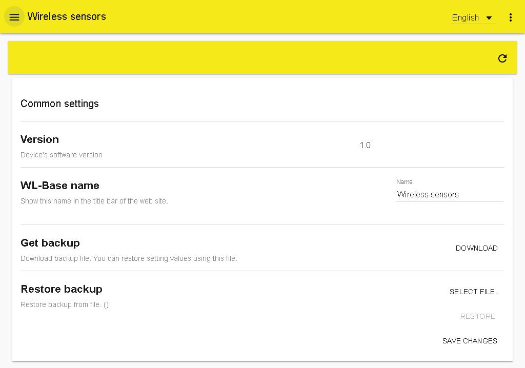
11 The base station will automatically retrieve the network settings once the device is connected to the network and the power is switched on. xx.xx.xx.xx xx.xx.xx.xx xx.xx.xx.xx xx.xx.xx.xx xx.xx.xx.xx You can open the function menu by clicking the three dot icon in the upper right corner of the Web UI. You can download a modbus CSV file, Ounet template and a Modbus RTU template onto your computer. The menu also includes the Web UI version information, password change, and logout.
. 80 x 85 x 30 mm Mounted to DIN bar 24 VAC / 5.5 VA or 10.")

12 Technical details Base station Case Operating temperature Protection class Measurement interval in installation mode Measurement interval in normal mode Dimensions Installation Operating voltage Power consumption in use Network size ABS plastic 0 C C IP20 10 seconds can be adjusted (1 240 min). 80 x 85 x 30 mm Mounted to DIN bar 24 VAC / 5.5 VA or VDC / 3W 12 VDC 160mA 24VDC 85mA 24 VAC 210mA up to 100 sensors Base station Access feature Built-in Web server to facilitate installation Short measurement interval in installation mode Ethernet, Modbus TCP/IP RS-485, Modbus RTU slave NOTE! Base station should not be connected to the public internet without firewall! That is, for example, a fixed IP address that is visible from outside network. Typically 3G-modem, adsl/wdsl/cable modem operates firewall functionality, wherein the separate accessory is not required. Temperature sensor: Built-in antenna Sensor coverage is not impaired when the battery is low. 868 MHz ZigBee technology Connector for outdoor temperature sensor (with a fixed cable connection to outside) Option to connect second temperature measurement, 0 10 V transmitter measurement or contact terminal information. OUMAN OY Temperature sensor / routing temperature sensor Case Operating temperature Protection class Measurement accuracy ABS plastic 0 C C IP C NTC-10 thermistor 10kΩ / 25 C AUX temperature measurement Operating temperature Measurement accuracy AUX 0-10VDC measurement accuracy Power source when used as temperature sensor Battery life (not included in delivery): Energizer L91 Ultimate Lithium 3100 mah: 15 min measurement interval 60 min measurement interval Energizer EN mah 15 min measurement interval 60 min measurement interval Key factors affecting battery life: Sampling interval Ambient temperature Sensor placed in a weak field (Occasionally dropped out from the network) External power source (operated as routing temperature sensor) Dimensions Installation -30 C C +/- 0.3 C 0.5% / 50mV 2 x AA batteries 9.5 years 11 years 6 years 7.5 years 5 VDC 80 x 85 x 30 mm Surface installation
Wireless Room Temperature and Humidity Transmitter (Units without Temperature Setpoint or Override) Installation and Operating Instructions
 Installation and Operating Instructions") Wireless Temperature and Humidity Overview and Indentification The Wireless Temperature and Humidity measures the room temperature and Relative Humidity and transmits the data at 418MHz or 433MHz RF to
Wireless Temperature and Humidity Overview and Indentification The Wireless Temperature and Humidity measures the room temperature and Relative Humidity and transmits the data at 418MHz or 433MHz RF to
TT-208. User s Manual. 300Mps 5.8 GHz. IP Camera Wireless Transmission Kit
 TT-208 300Mps 5.8 GHz IP Camera Wireless Transmission Kit User s Manual V1.0 02 / 2014 Welcome Thank you for purchasing the TT-208 Wireless Transmission Kit for IP Cameras. This user s manual is designed
Wireless 900 MHz Receiver
 Overview and Identification The 900 MHz unit receives a repeated or re-transmitted RF signal from one or more wireless temperature or humidity transmitters. The signal from the transmitter (418 MHz) is
Wireless LAN network. Wireless USB network
 Wireless data loggers for humidity and temperature Wireless systems Wireless Data Logger for Humidity and Temperature Probes. HygroClip2 probes for humidity and temperature measurement Wireless frequency:
AW900-SPEC USER S MANUAL
 USER S MANUAL 900 MHz Site Survey Spectrum Analyzer Industrial-grade, long-range wireless Ethernet systems AvaLAN W I R E L E S S User s Manual Thank you for your purchase of the AW900-SPEC Site Survey
Multi-Channel In-Out Thermometer with Cable Free Sensor and RF Clock
 Multi-Channel In-Out Thermometer with Cable Free Sensor and RF Clock MAIN FEATURES: MAIN UNIT GB MODEL: RMR182 USER'S MANUAL INTRODUCTION Congratulations on your purchase of the RMR182 Multi- Channel In-Out
3 GHz Carrier Backhaul Radio. Model: AF-3X. Tel: +44 (0) Fax: +44 (0) LINK GPS MGMT DATA DATA
 Fax: +44 (0) LINK GPS MGMT DATA DATA") LINK GPS MGMT DATA DATA MGMT GPS LINK 3 GHz Carrier Backhaul Radio Model: AF-3X LINK GPS MGMT DATA 3 GHz Carrier Backhaul Radio Model: AF-3X LINK GPS MGMT DATA DATA MGMT GPS LINK Introduction Thank you
LINK GPS MGMT DATA DATA MGMT GPS LINK 3 GHz Carrier Backhaul Radio Model: AF-3X LINK GPS MGMT DATA 3 GHz Carrier Backhaul Radio Model: AF-3X LINK GPS MGMT DATA DATA MGMT GPS LINK Introduction Thank you
Mx-RPW Room Control Module (Built-In Occupancy Sensor)
") Wireless Room Controller Application Solar-powered, self-learning room sensor with LCD and smart communication management for measuring room temperature, independent generation of utilization time profiles
Wireless Room Controller Application Solar-powered, self-learning room sensor with LCD and smart communication management for measuring room temperature, independent generation of utilization time profiles
AW5800-SPEC USER S MANUAL
 USER S MANUAL 5.8 GHz Site Survey Spectrum Analyzer Industrial-grade, long-range wireless Ethernet systems AvaLAN W I R E L E S S User s Manual Thank you for your purchase of the AW5800-SPEC Site Survey
AcuMesh Wireless RS485 Network. User's Manual SOLUTION
 AcuMesh Wireless RS485 Network User's Manual AN SOLUTION ACUMESH - WIRELESS METERING SYSTEM COPYRIGHT 2015 V1.2 This manual may not be altered or reproduced in whole or in part by any means without the
JUMO Wtrans E01. Measuring probe for humidity, temperature, and CO 2 with wireless data transmission. Brief description. Universal Wtrans receiver
 Page 1/13 JUMO Wtrans E01 Measuring probe for humidity, temperature, and CO 2 with wireless data transmission Humidity from 0 to 100 % RH (incl. -40 to +80 C) or CO 2 from 0 to 2000/5000/10000 ppm or Temperature
Operating Instructions
 LR650 Operating Instructions This product is an accessory or part of a system. Always read and follow the manufacturer s instructions for the equipment you are connecting this product to. Comply with all
Wireless LAN network. Wireless USB network
 Wireless data loggers for humidity and temperature Wireless systems Wireless Data Logger for Humidity and Temperature Probes. HygroClip 2 Probes for humidity and temperature measurement Wireless frequency:
Wireless systems.
 Wireless data loggers for humidity and temperature Wireless systems Wireless Data Logger for Humidity and Temperature Probes. HygroClip 2 Probes for humidity and temperature measurement Wireless frequency:
Connecting two Phoenix Studio Audiocodecs through a point-to-point IP radio link operating in the 5 GHz band
 APPLICATION NOTE Connecting two Phoenix Studio Audiocodecs through a point-to-point IP radio link operating in the 5 GHz band AEQ PHOENIX AUDIOCODECS. APPLICATION NOTE 4 Connecting two Phoenix Studio Audiocodecs
GR FAQS. La Crosse Technology, Ltd. Page 1
 308-1410GR FAQS The links below will work in most PDF viewers and link to the topic area by clicking the link. We recommend Adobe Reader version 10 or greater available at: http://get.adobe.com/reader
CONTENTS. La Crosse Technology, Ltd. Page 1
 WT-5220U-IT FAQS The links below will work in most PDF viewers and link to the topic area by clicking the link. We recommend Adobe Reader version 10 or greater available at: http://get.adobe.com/reader
WIRELESS BASE STATION WIRELESS CONFIGURATION TOOL WIRELESS REPEATER
 WIRELESS BASE STATION FLTA is a base station for wireless network transmitters and I/O modules. From FLTA, the controls and measurements can be read via Modbus RTU and through the analogue outputs. Respectively
Connecting two Phoenix Studio Audiocodecs through a point-to-point IP radio link operating in the 5 GHz band
 APPLICATION NOTE Connecting two Phoenix Studio Audiocodecs through a point-to-point IP radio link operating in the 5 GHz band AEQ PHOENIX AUDIOCODECS. APPLICATION NOTE 4-B Connecting two Phoenix Studio
Battery Powered People Counter with Integral LCD Display & 418Mhz Data Transmitter
 Battery Powered People with Integral LCD Display & 418Mhz Data Transmitter The SenSource PCW-TB06 is a battery powered people counter with 418Mhz RF wireless data transmitter. Truly wireless installation
Interface Manual Tank Level Float Stick System
 1 Interface Manual Tank Level Float Stick System SignalFire Model: Sentinel-FS-3BIS The SignalFire Sentinel Float Stick Node is an Intrinsically Safe device with the following features: - Standard SignalFire
Ethernet Gateway User Manual
 Ethernet Gateway User Manual Table of Contents Introduction At a Glance Getting Started Ethernet Gateway Setup via DHCP Ethernet Gateway Setup via Static IP Jacks, Buttons, and Ports Troubleshooting the
ZZxD-Nx-xR Series. Wireless Modbus I/O B&B ELECTRONICS PRODUCT INFORMATION
 Modular, Customizable Wire Replacement Modbus ASCII /RTU Compatible Wide Operating Temperature Active Repeater Functionality 10 to 48 VDC & 24 VAC Input Power Zlinx Wireless Modbus I/O - flexible enough
Installation Manual. 3 Phase Wireless Meter QC0142. Version: NOV16 1.0
 Installation Manual 3 Phase Wireless Meter QC0142 Manual Ref: QC0142 Version: NOV16 1.0 System Concept RF Transmitters connect to sensors or meters and send data to the infrastructure internet connected
LINK GPS MGMT DATA. 4 GHz Licensed Backhaul Radio DATA MGMT GPS. Model: AF-4X LINK
 LINK GPS MGMT DATA DATA MGMT GPS LINK 4 GHz Licensed Backhaul Radio Model: AF-4X 4 GHz Licensed Backhaul Radio Model: AF-4X LINK GPS MGMT DATA DATA MGMT GPS LINK Introduction Thank you for purchasing the
Zlinx Wireless I/O. Peer-to-Peer and Modbus I/O PRODUCT INFORMATION B&B ELECTRONICS
 Zlinx Wireless Modbus I/O-0712ds page 1/5 Modular, Customizable Wire Replacement 128 / 256 Bit AES Encryption Software Selectable RF Transmit Power Software Selectable Over-the-air Data Rate Modbus ASCII
AW2400iTR USER S MANUAL 2.4 GHz Indoor Wireless Ethernet Radio
 USER S MANUAL 2.4 GHz Indoor Wireless Ethernet Radio Industrial-grade, long-range wireless Ethernet systems AvaLAN W I R E L E S S Thank you for your purchase of the AW2400iTR Indoor Wireless Ethernet
RTS Reactive Target System
 RTS Reactive Target System RTS Electronic Target System Operating and User s Manual Introduction RTS (Reactive Target System) introduces a significant technological leap in erecting and managing wireless
WPR400 Wireless Portable Reader
 P516-098 WPR400 Wireless Portable Reader User guide Para el idioma español, navegue hacia www.schlage.com/support. Pour la portion française, veuillez consulter le site www.schlage.com/support. Contents
Door/Window Sensor User Manual HKWL DWS02W
 Door/Window Sensor User Manual HKWL DWS02W 1. PRODUCT OVERVIEW HKWL DWS02W is a Wi Fi wireless Door/Window sensor, you can monitor the status of your door/window in real time through your smart phone.
Eltek TU User Instructions for RP250GD and RP250GDS repeater
 Eltek TU 1007 - User Instructions for RP250GD and RP250GDS repeater Introduction The RP250GD repeater is a self contained mains operated data packet (GenII protocol only) repeater. The RP250GDS repeater
CONTENTS. Note: If using Alkaline Rechargeable battery place solar panel under light source for 6 hours with rechargeable battery in place to charge.
 WS-6020U-IT FAQS The links below will work in most PDF viewers and link to the topic area by clicking the link. We recommend Adobe Reader version 10 or greater available at: http://get.adobe.com/reader
Installation Manual Multi Input Temperature Logger QC0163. Manual Ref: QC0163. Version: FEB17 1.0
 Installation Manual 3999-913-2252 Multi Input Temperature Logger QC0163 Manual Ref: QC0163 Version: FEB17 1.0 System Concept RF Transmitters connect to sensors or meters and send data to the infrastructure
433 MHZ TEMPERATURE STATION Instruction Manual
 433 MHZ TEMPERATURE STATION Instruction Manual INTRODUCTION: Congratulations on purchasing this innovative 433MHz Temperature Station which displays the time with up to the minute indoor and up to three
Installation Instructions
 SYSTXBBSAM01 EVOLUTION SYSTEM ACCESS MODULE Installation Instructions NOTE: Read the entire instruction manual before starting the installation. pointsett U.S. Pat No. 7,415,102 Fig. 1 - Evolution System
Disclaimers. Important Notice
 Disclaimers Disclaimers Important Notice Copyright SolarEdge Inc. All rights reserved. No part of this document may be reproduced, stored in a retrieval system, or transmitted, in any form or by any means,
Connecting Mains Electrical Power
 Tide Level Monitoring Instrumentation The following documentation details the electrical installation for the tide level monitoring instrumentation and also a summary of the logger configurations required
Wireless Sensor for Humidity / Temperature / CO 2
 Series State of the art sensor technology, highest reliability of data transmission and the ease of system installation are the outstanding features of the wireless sensor series. With a modular structure
WIRELESS MODBUS GATEWAY WGW410
 WIRELESS MODBUS GATEWAY WGW410 The Tekon Wireless Modbus Gateway WGW410 is specifically designed to meet the most rigorous requirements of operation in the industrial process environments. Due to their
USB Meter Reader. Data sheet. For reading Kamstrup consumption meters
 Data sheet USB Meter Reader For reading Kamstrup consumption meters Reading system for reading Kamstrup MULTICAL meters via M-Bus and wireless M-Bus Mode C1, 434 MHz radio as well as flowiq water meters
LincView OPC USER GUIDE. Enhanced Diagnostics Utility INDUSTRIAL DATA COMMUNICATIONS
 USER GUIDE INDUSTRIAL DATA COMMUNICATIONS LincView OPC Enhanced Diagnostics Utility It is essential that all instructions contained in the User Guide are followed precisely to ensure proper operation of
Wireless Rain and Wireless Rain/Freeze Sensor
 Wireless Rain and Wireless Rain/Freeze Sensor Installation and Operating Instructions for: WRC: Wireless Rain Sensor Combo WRT: Wireless Rain Sensor Transmitter WSR: Wireless Rain Sensor Receiver WRFC:
RF Wireless Serial Device Server
 RF-SDS RF Wireless Serial Device Server The RF-SDS subassembly is a radio transceiver acting as a Serial Device Server, which externally connects a remote serial RF transceiver to an Ethernet network (TCP/IP).
Remote Site Monitoring
 Remote Site Monitoring FEATURES AT A GLANCE Codan Radio Communications now offers Remote Site Monitoring options that provide live site information, giving you the power to respond intelligently to communications
MPR kHz Reader
 MPR-5005 Page 1 Doc# 041326 MPR-5005 125kHz Reader Installation & Operation Manual - 041326 MPR-5005 Page 2 Doc# 041326 COPYRIGHT ACKNOWLEDGEMENTS The contents of this document are the property of Applied
TS-WS-07 Wireless Indoor/Outdoor 8-Channel Thermo-Hygrometer with Jumbo Display User Manual
 TS-WS-07 Wireless Indoor/Outdoor 8-Channel Thermo-Hygrometer with Jumbo Display User Manual Table of Contents 1. Introduction......2 2.Getting Started.....2 2.1 Parts List.......2 2.2 Recommend Tools.........2
Wireless CO 2. + TRH Sensor. Installation Guide. Version 1
 Wireless CO 2 + TRH Sensor Installation Guide Version 1 2 CO2 + TRH Sensor Installation Guide Introduction The wireless CO 2 + TRH (Carbon Dioxide + Temperature and Relative Humidity) sensor is a wall
Wireless Analog Output Modules
 Overview and Product Identification Wireless Analog s Analog s receive data from a BAPI 418 MHz receiver or 900 MHz receiver through a four-wire RS 485 bus. Up to 127 different Analog s can be connected
Installation Manual. Temp Tx-Sensor with Micro switch QC0164. Version: FEB17 1.0
 Installation Manual Temp Tx-Sensor with Micro switch QC0164 Manual Ref: QC0164 Version: FEB17 1.0 System Concept RF Transmitters connect to sensors or meters and send data to the infrastructure internet
WLS (Wireless Locating System)
") WLS () Introduction can be used in indoor and outdoor environments. It can monitor the exact location of certain objects or persons and integrate the location information into the back-end servers. In
WLS () Introduction can be used in indoor and outdoor environments. It can monitor the exact location of certain objects or persons and integrate the location information into the back-end servers. In
9/2/2013 Excellent ID. Operational Manual eskan SADL handheld scanner
 9/2/2013 Excellent ID Operational Manual eskan SADL handheld scanner Thank You! We are grateful you chose Excellent ID for your SADL scanner needs. We believe this easy-to-use scanner will provide dependable
MAXI Remote Location Kit MRLK 900 Installation and Configuration Manual
 MAXI Remote Location Kit MRLK 900 Installation and Configuration Manual 01/18 635079 Table of Contents Introduction... 3 Materials Included... 3 Setup Overview... 4 Radio Configuration Overview:... 4 FreeWaveTool
Remote Sensor Manual. User Guide. Revision A.0
 Remote Sensor Manual User Guide Revision A.0 Contents Remote Sensor User Manual... 3 Connecting Power... 3 Basic Sensor Operation... 4 Basic Sensor Operation with Data Logging... 5 Sensor Calibration Button...
INSTALLATION MANUAL. Model: Smart Analyzer Manufacturer: Smart Impulse. Power meter with consumption breakdown by use 03/12/13
 INSTALLATION MANUAL Model: Smart Analyzer Manufacturer: Smart Impulse Power meter with consumption breakdown by use 03/12/13 Table of contents Table of contents... 2 1. Introduction... 3 2. Installation
Firmware version 1.05 supports all CMOS sensor based digital backs IQ150, IQ250 and A- series IQ250.
 RELEASE NOTE January, 2015 Firmware version 1.05 for IQ150, IQ250 and A-series IQ250 Firmware version 1.05 supports all CMOS sensor based digital backs IQ150, IQ250 and A- series IQ250. New functionality
WIRELESS 868 MHz WEATHER STATION
 WIRELESS 868 MHz WEATHER STATION Instructions Manual INTRODUCTION: Congratulations on purchasing this Weather Station with wireless 868 MHz transmission of outdoor temperature and display of indoor temperature,
Installation Manual. Ultra RF Analogue Transmitter QC0168. Manual Ref: QC0168. Version: March
 Installation Manual Ultra RF Analogue Transmitter QC0168 Manual Ref: QC0168 Version: March 17 1.0 System Concept RF Transmitters connect to sensors or meters and send data to the infrastructure internet
Wireless Time Distribution WTD
 Proud Partners with MOBATime Wireless Time Distribution WTD The innovative radio clock system is based on a transmitter which sends the time signal (868 MHz) to the end devices (i.e. clocks). The end devices
Catalog
 - 1 - Catalog 1. Description...- 3-2. Features...- 3-3. Applications... - 3-4. Block Diagram...- 3-5. Electrical Characteristics... - 5-6. Operation... - 5 - Power on Reset... - 5 - Working mode... - 6
RSMFX-2R MULTIFUNCTIONAL
 Mounting and operating instructions Table of contents SAFETY AND PRECAUTIONS 3 PRODUCT DESCRIPTION 4 ARTICLE CODES 4 INTENDED AREA OF USE 4 TECHNICAL DATA 4 STANDARDS 4 OPERATIONAL DIAGRAMS 5 WIRING AND
GPSR400 Quick Start Guide
 GPSR400 Quick Start Guide Rev. 6 Introduction Microlab s digital GPS repeater system can be used for cellular communications UTC synchronization for locations where the GPS signals are not readily available.
P2P 2 YEAR PL-VDIO-05. Smartphone Connect IP VIDEO DOOR PHONE QUICK START GUIDE 7 VIDEO DOOR PHONE SYSTEM WITH SMARTPHONE CONNECT
 PL-VDIO-05 IP VIDEO DOOR PHONE QUICK START GUIDE Smartphone Connect 2 YEAR RR T SERVICES WA P2P Y Receive calls, remote monitor and remote unlock with your smart phone AN 7 VIDEO DOOR PHONE SYSTEM WITH
Install Guide. EMPower03 Power Monitor 1.1
 created JL Install Guide Rev. Nr. 1.1 EMPower03 Power Monitor checked -- valid from 28.11.2013 This guide describes how to install the Energy Matters EMPower03 power monitor. The power monitor measures
COD GB / 1.0 RBAND/UMS - RBAND/CSM
 INTRODUCTION DESCRIPTION The RadioBand system is designed of Industrial, Commercial and Domestic door and gate applications where a safety edge is used. The system provides a wireless system replacing
GPSR116 Quick Start Guide
 GPSR116 Quick Start Guide .21 [ 5,3] [482,6] 18.12 [460,3] GPSR116 Quick Start Guide Rev 2.35 [8,9] Introduction Microlab s digital GPS repeater system can be used for cellular communications UTC synchronization
Wireless Network Manager (NM) and Wireless Transceiver (TRV)
 and Wireless Transceiver (TRV)") R Installation and Operation Instructions Wireless Network Manager (NM) and Wireless Transceiver (TRV) for PLATINUM CONTROLS With COMMUNICATION The New Heat-Timer Wireless Network Sensor System is designed
R Installation and Operation Instructions Wireless Network Manager (NM) and Wireless Transceiver (TRV) for PLATINUM CONTROLS With COMMUNICATION The New Heat-Timer Wireless Network Sensor System is designed
Wireless Temp/Setpoint & Override Room Transmitter
 Overview The BAPI Wireless Combination Transmitter measures the room temperature and relative humidity and transmits the data at 418MHz or 433MHz RF to a receiver. Temperature setpoint and override button
Planning Guidelines. Lightcloud. Best Practices for Installing Lightcloud
 Best Practices for Installing Lightcloud Planning Guidelines Lightcloud Network Wireless Networking Considerations Wireless Mesh Network Placement of Devices Powering Devices Placing the Gateway Installation
MLR-1105 (DC battery type door chime receiver) LMLT-711 (push unit door chime transmitter)
 LMLT-711 (push unit door chime transmitter)") MODEL: MLR-1105 (DC battery type door chime receiver) LMLT-711 (push unit door chime transmitter) FEATURE: * 67 million self-learning coding RF wireless operation system. No interference with neighbors.
MODEL: MLR-1105 (DC battery type door chime receiver) LMLT-711 (push unit door chime transmitter) FEATURE: * 67 million self-learning coding RF wireless operation system. No interference with neighbors.
MICROWAVE MOISTURE SENSOR WITH WIRELESS DATA TRANSMISSION FL-WAPP
 - 1 MICROWAVE MOISTURE SENSOR WITH WIRELESS DATA TRANSMISSION FL-WAPP INDEX General Function Description P. 2 Technical Data P. 2 1. Software Installation P. 3 2. System Integration P. 3 2.1 Sensor as
HT1000 Satellite Modem Installation Guide
 HT1000 Satellite Modem Installation Guide 1039110-0001 Revision A October 17, 2012 11717 Exploration Lane, Germantown, MD 20876 Phone (301) 428-5500 Fax (301) 428-1868/2830 Copyright 2012 Hughes Network
Ambient Weather WS-0270 Wireless Indoor / Outdoor Thermometer with Indoor Humidity User Manual
 Ambient Weather WS-0270 Wireless Indoor / Outdoor Thermometer with Indoor Humidity User Manual Table of Contents 1 Introduction... 1 2 Getting Started... 1 2.1 Parts List... 2 2.2 Recommend Tools... 2
Electrical devices may only be mounted and connected by electrically skilled persons.
 enet Server Order No. : 5301 00 Power adapter enet Server 12 V DC Operating instructions 1 Safety instructions Electrical devices may only be mounted and connected by electrically skilled persons. Serious
PM8005/6 PM8005/6. Panel Meter Panel Meter. AC and DC supply options. 5 digit LED display. Direct access menu
 PM8005/6 AC and DC supply options 5 digit LED display Direct access menu Functions for calibration, alarm setting and more Wide range of optional functions Description The PM8000 Series digital panel meters
Installation guide. Activate. Install your TV. Uninstall. 1 min 10 mins. 30 mins
 Installation guide 1 Activate 2 Uninstall 3 Install your TV 1 min 10 mins 30 mins INT This guide contains step-by-step instructions on how to: 1 Activate Before we do anything else, reply GO to the text
AUTOMATIC WEATHER AND HYDROLOGICAL STATIONS
 AUTOMATIC WEATHER AND HYDROLOGICAL STATIONS METEODATA/HYDRODATA-3000C SERIES Brochure nº 9722.0044 GEONICA, S.A. - Alejandro Rodríguez, nº 22-28039 Madrid - Spain Tel. +34 91 450 51 18 Fax +34 91 459 46
Yara Water Solution. Installation Guide. Product summary: - Included components - Tools for setup - Installation overview
 Yara Water Solution Installation Guide Product summary: - Included components - Tools for setup - Installation overview Step by step installation guide: - Mounting the Base Station - Preparing the field
ROAM XL. Commercial Remote Control. ROAM XL Commercial Remote Control Owner s Manual and Programming Instructions
 ROAM XL Commercial Remote Control ROAM XL Commercial Remote Control Owner s Manual and Programming Instructions A TABLE OF CONTENTS INTRODUCTION... 2 ROAM XL COMPONENTS... 3 TRANSMITTER RECEIVER SmartPort
Astra-R Kit Wireless Alarm System Operation Manual
 Astra-R Kit Wireless Alarm System Operation Manual This operation manual describes principles of functioning, proper use, maintenance and service for the wireless alarm system Astra- R Kit (Figure 1).
Catalogue
 - 1 - Catalogue 1. Description... - 3-2. Features... - 3-3. Applications...- 3-4. Block Diagram... - 3-5. Electrical Characteristics...- 4-6. Operation...- 5 - Power on Reset... - 5 - Working mode... -
433 MHZ REMOTE THERMO
 433 MHZ REMOTE THERMO INTRODUCTION: Congratulations on purchasing this innovative 433MHz Remote Thermo which displays the time with up to the minute indoor and up to five outdoor temperature readings.
SV-MESH Mesh network series Catalogue
 Catalogue 1. Description... 3 2. Features... 3 3. Applications... 3 4. Block Diagram... 4 5. Electrical Characteristics... 5 6. Operation... 5 Power on Reset... 5 Working mode... 6 Router mode... 8 Setting
CONTENTS. Batteries. Half of all warranty issues can be resolved with fresh batteries of the appropriate voltage. La Crosse Technology, Ltd.
 308-1409BT-308-1409WT FAQS The links below will work in most PDF viewers and link to the topic area by clicking the link. We recommend Adobe Reader version 10 or greater available at: http://get.adobe.com/reader
English RACON SERIES II RADIO CONTROL SERVICE MANUAL
 English 22.2.2007 RACON SERIES II RADIO CONTROL SERVICE MANUAL Read the instructions supplied with the product before installation and commissioning. Keep the instructions in a safe place for future reference.
XLR PRO Radio Frequency (RF) Modem. Getting Started Guide
 Modem. Getting Started Guide") XLR PRO Radio Frequency (RF) Modem Getting Started Guide XLR PRO Radio Frequency (RF) Modem Getting Started Guide 90002203 Revision Date Description A September 2014 Initial release. B March 2014 Updated
XLR PRO Radio Frequency (RF) Modem Getting Started Guide XLR PRO Radio Frequency (RF) Modem Getting Started Guide 90002203 Revision Date Description A September 2014 Initial release. B March 2014 Updated
Wireless Sensor for Humidity / Temperature / CO 2
 State of the art sensor technology, highest reliability of data transmission and the ease of system installation are the outstanding features of the wireless sensor series EE240. Wireless Sensor for Humidity
DPA602 1/7. Multi-Channel Network Amplifier. General Description. Features. Applications. AtlasIED.com. DPA602 Front. DPA602 Back
 1/7 DPA602 Multi-Channel Network Amplifier Features Configurations 2 x 300 Watt 70V / 100V (Factory Default) 4 x 150 Watt @ 4Ω 1 x 300 Watt 70V / 100V & 2 x 150 Watt @ 4Ω No Computer Required to Operate
WPR400 Wireless Portable Reader User guide
 *P516-098* P516-098 WPR400 Wireless Portable Reader User guide Para el idioma español, navegue hacia www.allegion.com/us Pour la portion française, veuillez consulter le site www.allegion.com/us Contents
11 GHz FDD Licensed Backhaul Radio. Model: AF 11FX
 11 GHz FDD Licensed Backhaul Radio Model: AF 11FX 11 GHz FDD Licensed Backhaul Radio Model: AF 11FX Introduction Thank you for purchasing the Ubiquiti Networks airfiber AF 11FX. This Quick Start Guide
CUSTOMER MANUAL. ERDCHS1 Series. Indoor/Outdoor Channelized Digital Repeaters JANUARY 18,
 CUSTOMER MANUAL ERDCHS1 Series Indoor/Outdoor Channelized Digital Repeaters JANUARY 18, 2018 WWW.EXCELWAVETECHNOLOGIES.COM 1-888-329-2878(Tel) 1-888-318-5528(Fax) Contents Disclaimer... 2 QUICK START...
Table of Contents. Chapter 1: Software Installation...1. Chapter 2: Running the Software II. Daily Practical Operation...10
 Product Manual Table of Contents Chapter 1: Software Installation.................................1 Chapter 2: Running the Software............................... 2 I. The Initial Defining in Lock Management
INSTRUCTION MANUAL FOR ULTRASONIC/MICROWAVE SENSORS
 INSTRUCTION MANUAL FOR ULTRASONIC/MICROWAVE SENSORS 1)Install PROBE_GatewayPC Software on PC.Remove previous installation. In Windows Control Panel go to the Programs and Features, select Probe_GatewayPC_Net
Series EE240. Manual. Hardware and Software CO 2. BA_EE240_04_e // technical data are subject to change //
 Series EE240 Wireless SENSOR FOR HUMIDITY TEMPERATURE CO 2 Manual Hardware and Software BA_EE240_04_e // technical data are subject to change // 350118 USA FCC information: This equipment is tested and
M2M i-link POINT-TO-MULTIPOINT INSTALLATION INSTRUCTIONS
 M2M i-link POINT-TO-MULTIPOINT INSTALLATION INSTRUCTIONS 1 TABLE OF CONTENTS 1 TABLE OF CONTENTS... 2 2 GENERAL... 3 3 INSTALLATION... 4 3.1 SUB-STATIONS... 4 3.2 MAIN STATION (PC)... 4 4 CONNECTING THE
P700-WLS ioprox Receiver
 Installation Manual DN1628-1611 Pre-Installation Notes Copyright 2016 Tyco International Ltd. and its Respective Companies. All Rights Reserved. All specifications were current as of publication date and
Home Automation, Inc. Model 12A00. Wireless Receiver. Installation Manual
 Home Automation, Inc. Model 12A00 Wireless Receiver Installation Manual Document Number 12I00 Rev D August, 2002 CONTENTS DESCRIPTION...1 COMPATIBLE TRANSMITTERS...1 INSTALLATION...2 OPERATION...3 SETUP
Yara Water Solution. Installation Guide. Product summary: - Included components - Tools for setup - Installation overview
 Yara Water Solution Installation Guide Product summary: - Included components - Tools for setup - Installation overview Step by step installation guide: - Mounting the Base Station - Preparing the field
User's Manual F10G-5S-LCD 1 / 20 BOOST CELL PHONE SIGNAL BOOSTERS MADE BY HUAPTEC
 User's Manual F10G-5S-LCD 1 / 20 BOOST CELL PHONE SIGNAL BOOSTERS MADE BY HUAPTEC Table of contents WHAT IS INCLUDED... 3 1 HOW IT WORKS... 3 2 TOOL REQUIRED... 3 3 HOW TO INSTALL YOUR NEW CELLULAR BOOSTER...
Dear Valued Customer,
 Dear Valued Customer, Thank you for choosing Listen! All of us at Listen are dedicated to provide you with the highest quality products available. We take great pride in their outstanding performance because
HN9200 Satellite Modem Installation Guide
 HN9200 Satellite Modem Installation Guide 1038622-0001 Revision B March 2, 2011 Copyright 2010-2011 Hughes Network Systems, LLC All rights reserved. This publication and its contents are proprietary to