Switching and control professionals electronic switching relays, control relays and coupling relays
|
|
|
- Vernon Eaton
- 5 years ago
- Views:
Transcription


1 12 Switching and control professionals electronic switching relays, control relays and coupling relays 12


2 Electronic switching relays, control relays and coupling relays Selection table switching relays, control relays and coupling relays 12-2 Switching relay ER12DX 12-3 Switching relay ER Impulse switch with integrated relay function ESR12NP 12-5 Digital settable multifunction impulse switch with integrated relay function ESR12DDX 12-6 Switching and control relays ER Coupling relays KR Switching relay ER61 and impulse switch with integrated relay function ESR61NP 12-9 Multifunction impulse switch with integr. relay function ESR61M Isolating relay ETR61NP Isolating relay ETR61NP with window contact FK Technical data electronic switching relays, control relays and coupling relays
3 Selection Table Switching Relays, Control Relays and Coupling Relays Switching and control professionals Professional hybrid relays combine the advantages of nonwearing electronic control with high switching capacity of special relays. We also use mainly bistable relays. Thus preventing coil power loss even in the on mode. This increases energy effi ciency and reduces heating in the switch cabinet. Page pictograms ER12DX-UC ER UC ER UC ESR12NP-230 V+UC ESR12DDX-UC ER UC ER UC KR09-12 V UC, 24V UC, 230 V ER61-UC ESR61NP-230V+UC ESR61M-UC ETR61NP-230V (+FK) Modular device for mounting on DIN rail EN TH35, number of modules 18mm each Built-in device for installation (e.g. fl ush-mounting box) Number NO contacts or changeover contact (W) potential free (not potential free) ½ (1) 1+1 2) 2 2) 1W 2W 1 1W (1) Number NC contacts potential free ) 1-2 2) Zero passage switching 7) 7) 1+1 2) 2 2) (1) 12-2 Switching capacity 16A/250V AC Switching capacity 10A/250V AC 6A Incandescent lamp load W Bistable relay(s) as relay contact(s) 5) 5) 5) 6) 5) 5) 5) 6) 5) Switchable between the functions for impulse switches and switching relays Universal control voltage (additional) control voltage 230V ( ) ( ) Supply voltage same as control voltage Supply voltage 230V 3) No standby loss 7) Low standby loss 7) Glow lamp current (ma) at the control input 230V 150 1) 1) 4) ) Glow lamp current independent from the ignition voltage. 2) Depends on the set function. 3) If the control voltage is 230V, but the phase conductor is different from the 230V supply voltage, the universal voltage control input must be used. 4) At the control input. 5) The relay contact can be open or closed when putting into operation. It will be synchronised at first operation. 6) The switched consumer may not be connected to the mains before the short automatic synchronisation after installation has terminated. 7) Patented duplex technology: When switching 230V/50Hz the contact switching takes place in the zero passage when L is connected to (L) and N to (N). The standby loss is then 0.1 Watt.
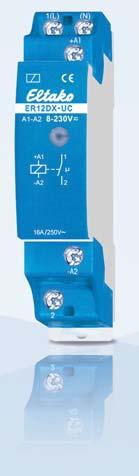
4 Switching Relay ER12DX ER12DX-UC If N is connected, the zero passage switching is active. 1 NO contact potential free 16A/250V AC, incandescent lamp load up to 2000W. No standby loss. Modular device for DIN-EN TH35 rail mounting. 1 module = 18mm wide, 58mm deep. With the patented Eltako Duplex technology (DX) the normally potential-free contacts can still switch in zero passage when switching 230V AC 50Hz and therefore drastically reduce wear. Simply connect the neutral conductor to the terminal (N) and L to 1(L) for this. This gives an standby consumption of only 0.1 Watt. If the contact is used for controlling switching devices which do not perform zero passage switching themselves, (N) should not be connected because the additional closing delay otherwise causes the opposite effect. Universal control voltage 8 to 230V UC. Very low switching noise. Contact position indicator with LED. Same terminal connection as electromechanical switching relay R By using a bistable relay coil power loss and heating is avoided even in the on mode. The relay contact can be open or closed when putting into operation. It will be synchronised at first operation. This relay is not suitable to feed back the switching voltage signal of a dimmer switch. Use only relays ESR12DDX-UC, ESR12NP-230V+UC or ESR61NP-230V+UC for this purpose. The electronics does not have an internal power supply and therefore no standby loss. The microcontroller is activated when the control contact closes. This switches the bistable relay to the correct direction. The bistable relay switches back either when the control contact opens or when the control voltage falls Housing for operating instructions GBA12, see accessoirs, chapter Z. ER12DX-UC 1 NO 16A EAN ,40 / pc.

5 Switching Relay ER12 ER UC 1 3 +A1 4 -A NO contacts potential free 16A/250V AC, incandescent lamp load up to 2000W. No standby loss. Modular device for DIN-EN TH35 rail mounting. 1 module = 18mm wide, 58mm deep. Universal control voltage 8 to 230V UC. Very low switching noise. Contact position indicator with LED. Maximum current across both contacts 16A for 230V. Same terminal connection as electromechanical switching relay R By using a bistable relay coil power loss and heating is avoided even in the on mode. The relay contact can be open or closed when putting into operation. It will be synchronised at first operation. This relay is not suitable to feed back the switching voltage signal of a dimmer switch. Use only relays ESR12DDX-UC, ESR12NP-230V+UC or ESR61NP-230V+UC for this purpose Housing for operating instructions GBA12, see accessoirs, chapter Z. The electronics does not have an internal power supply and therefore no standby loss. The microcontroller is activated when the control contact closes. This switches the bistable relay to the correct direction. The bistable relay switches back either when the control contact opens or when the control voltage falls. ER UC 2 N0 16A EAN ,80 /pc. ER UC 1 NO + 1 NC contact potential free 16A/250V AC, incandescent lamp load up to 2000W. No standby loss. Modular device for DIN-EN TH35 rail mounting. 1 module = 18mm wide, 58mm deep. Universal control voltage 8 to 230V UC. Very low switching noise. Contact position indicator with LED. Same terminal connection as electromechanical switching relay R By using a bistable relay coil power loss and heating is avoided even in the on mode. The relay contact can be open or closed when putting into operation. It will be synchronised at first operation. This relay is not suitable to feed back the switching voltage signal of a dimmer switch. Use only relays ESR12DDX-UC, ESR12NP-230V+UC or ESR61NP-230V+UC for this purpose. Housing for operating instructions GBA12, see accessoirs, chapter Z. The electronics does not have an internal power supply and therefore no standby loss. The microcontroller is activated when the control contact closes. This switches the bistable relay to the correct direction. The bistable relay switches back either when the control contact opens or when the control voltage falls. ER UC 1 NO + 1 NC 16 A EAN ,80 / pc.

6 Impulse Switch with integrated relay function ESR12NP ESR12NP-230V+UC Function rotary switches Standard setting ex works. = switch-off early warning = pushbutton permanent light = switch-off early warning and pushbutton permanent light 1 NO contact not potential free 16A/250V AC, incandescent lamp load up to 2300W. Off delay impulse switch with switch-off early warning and pushbutton permanent light switchable. Standby loss 0.5 watt only. Modular device for DIN-EN TH35 rail mounting. 1 module = 18mm wide, 58mm deep. Zero passage switching to protect contacts and lamps. This prolongs in particular the lifetime of energy saving lamps. Control voltage 230V. In addition electrically isolated universal voltage from 8 to 230V UC. Supply voltage and switching voltage 230V. Very low switching noise. If the function ESV is set, defi nitely variable off-delay time RV from 2 to 120 minutes, settable by minute scale. Contact position indication with two LEDs. This starts blinking in case of a blocked pushbutton (not if the function ER is set). Glow lamp current up to 150mA only at the control input 230V independent from ignition voltage (not if the function ER is set). Relays with suitable functions to feed back the switching voltage signal of a dimmer switch. In case of a power failure the system is disconnected in a preset sequence. The functions ES, ESV or ER are selectable by means of a rotary switch. ES = Impulse switch ER = Switching relay ESV = Impulse switch with off delay. The impulse switch automatically disconnects after the set delay is timed out if a manual OFF command has not been given. Infi nitely variable time range up to 120 minutes. ESV = If switch-off early warning is set the stairwell lighting starts fl ickering approximately + 30 seconds before timeout at repeated shorter time intervals. During this process reset is possible. ESV = If push-button permanent light is set permanent light can be switched on by + pressing longer than 1 sec. This switches off automatically after 2 hours or by an operation longer than 2 seconds. ESV If both switch-off early warning function and permanent light by push-button are + set, the switch-off early warning function is activated before switching off the permanent light. This electronic impulse switch does not need a base load for switching lights in rooms which are monitored by a FR12-230V mains disconnection relay V UC μ + N L +C1 -C2 N L L N ESR12NP-230V+UC 1 N0 16A EAN ,40 / pc. Housing for operating instructions GBA12, see accessoirs, chapter Z.

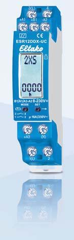
7 Digital settable Multifunction Impulse Switch with integrated relay function ESR12DDX ESR12DDX-UC 12-6 If N is connected, the zero passage switching is active V UC checkback signal Housing for operating instructions GBA12, see accessoirs, chapter Z. 1+1 NO contacts potential free 16A/250V AC. Incandescent lamp load up to 2000W. Standby loss watt only. Modular device for DIN-EN TH35 rail mounting. 1 module = 18mm wide, 58mm deep. With the patented Eltako Duplex technology (DX) the normally potential-free contacts can still switch in zero passage when switching 230V AC 50Hz and therefore drastically reduce wear. Simply connect the neutral conductor to the terminal (N) and L to 1(L) and/or 3(L) for this. This results in an additional standby consumption of only 0.1 Watt. Universal control voltage 8 to 230V UC. Supply voltage is same as the control voltage. The functions are set with the keys MODE and SET as described in the operating instructions. They are indicated on the display and can be blocked if required. The accrued switch-on time is continuously displayed. First in hours (h), then in months (m) with 1 digit after the decimal point. By using bistable relays coil power loss and heating is avoided even in the on mode. The switched consumer may not be connected to the mains before the short automatic synchronisation after installation has terminated. Only impulse switch functions: After a power failure the system is disconnected in a definite sequence or the switch position is kept depending on the setting (then + on the display next to function abbreviations). Settings under RSM in the menu guidance. Furthermore, when using these functions, with the keys MODE and SET, the control inputs A1 and A3 can be defined as central control inputs. ZA1 = 'central off' with A1, local with A3; ZE1 = 'central on' with A1, local with A3; Z00 = no central control. 'Central on' with A1, 'central off' with A3. No local control refer to function RS. Relays with suitable functions to feed back the switching voltage signal of a dimmer switch. From 110V control voltage and in the settings 2S, WS, SS and GS glow lamp current up to 5mA, dependent on the ignition voltage. With the keys MODE and SET you can select amongst 18 functions: OFF = Permanent OFF 2xS = 2-fold impulse switch with 1 NO contact each, control inputs A1 and A3 2S = Impulse switch with 2 NO contacts WS = Impulse switch with 1 NO contact and 1 NC contact SS1 = Impulse multi circuit switch 1+1 NO contacts for switching sequence 0 - contact 1(1-2) - contact 2 (3-4) - contacts SS2 = Impulse multi circuit switch 1+1 NO contacts for switching sequence 0 - contact 1 - contacts contact 2 SS3 = Impulse multi circuit switch 1+1 NO contacts for switching sequence 0 - contact 1 - contacts GS = Impulse group switch 1+1 NO contacts for switching sequence 0 - contact contact 2 RS = Switch with 2 NO contacts, with A1 = set control input and A3 = reset control input 2xR = 2-fold switching relay with 1 NO contact each, control inputs A1 and A3 2R = Switching relay with 2 NO contacts WR = Switching relay with 1 NO contact and 1 NC contact RR = Switching relay (closed-circuit current relay) with 2 NC contacts EAW = Impulse relay for fleeting NO contact and fleeting NC contact with 1+1 NO contacts, wiping time 1 sec each EW = Impulse relay for fleeting NO contact with 1 NO contact and 1 NC contact, wiping time 1 sec AW = Impulse relay fleeting NC contact with 1 NO contact and 1 NC contact, wiping time 1 sec GR = Group relay 1+1 NO contacts (relay with alternating closing contacts) ON = Permanent ON The control inputs A1 and A3 have the same functions except for 2xS, 2xR and RS, if not used as central control inputs. After setting the required function, the function can be blocked. An arrow on the right of the abbreviation indicates the blocking status. ESR12DDX-UC 1+1 NO 16A EAN ,60 /pc.
8 Switching and Control Relays ER12 ER UC 1 CO contact potential free 16A/250V AC, incandescent lamp load up to 2000W. No standby loss. Modular device for DIN-EN TH35 rail mounting. 1 module = 18mm wide, 58mm deep. Universal control voltage 8 to 230V UC. Low control power demand, therefore substantially less heat is generated. Integrated free-wheeling anti-surge diode (A1 = +, A2 = -). Safe disconnection to VDE 0106, Part 101; therefore, these devices can also be used as coupling relays. By using a bistable relay coil power loss and heating is avoided even in the on mode. The relay contact can be open or closed when putting into operation. It will be synchronised at first operation. This relay is not suitable to feed back the switching voltage signal of a dimmer switch. Use only relays ESR12DDX-UC, ESR12NP-230V+UC or ESR61NP-230V+UC for this purpose. Housing for operating instructions GBA12, see accessoirs, chapter Z. The electronics does not have an internal power supply and therefore no standby loss. The microcontroller is activated when the control contact closes. This switches the bistable relay to the correct direction. The bistable relay switches back either when the control contact opens or when the control voltage falls. ER UC 1 CO 16 A EAN ,30 / pc ER UC 2 CO contacts potential free 16A/250V AC, incandescent lamp load up to 2000W. No standby loss. Modular device for DIN-EN TH35 rail mounting. 1 module = 18mm wide, 58mm deep. Low switching noise. Contact position indicator with LED. Integrated free-wheeling anti-surge diode (A1 = +, A2 = -). By using a bistable relay coil power loss and heating is avoided even in the on mode. The relay contact can be open or closed when putting into operation. It will be synchronised at first operation. This relay is not suitable to feed back the switching voltage signal of a dimmer switch. Use only relays ESR12DDX-UC, ESR12NP-230V+UC or ESR61NP-230V+UC for this purpose. The electronics does not have an internal power supply and therefore no standby loss. The microcontroller is activated when the control contact closes. This switches the bistable relay to the correct direction. The bistable relay switches back either when the control contact opens or when the control voltage falls. ER UC 2 CO 16 A EAN ,60 /pc. Housing for operating instructions GBA12, see accessoirs, chapter Z.
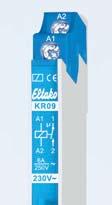
9 Coupling Relays KR09 KR09-12V UC 1 NO contact potential free 6A/250V AC, incandescent lamp load up to 500W. No standby loss. Modular device for DIN-EN TH35 rail mounting. 1/2 module = 9mm wide, 55mm deep. Control voltages 12V UC. Contact position indicator with LED. Control power demand 0.2W only. Safe disconnection to VDE 0106, Part 101; therefore, these devices can also be used as coupling relays. Housing for operating instructions GBA12, see accessoirs, chapter Z. KR09-12V UC 1 N0 6A EAN ,20 /pc. KR09-24V UC NO contact potential free 6A/250V AC, incandescent lamp load up to 500W. No standby loss. Modular device for DIN-EN TH35 rail mounting. 1/2 module = 9mm wide, 55mm deep. Control voltages 24V UC. Contact position indicator with LED. Control power demand 0.2W only. Safe disconnection to VDE 0106, Part 101; therefore, these devices can also be used as coupling relays. Housing for operating instructions GBA12, see accessoirs, chapter Z. KR09-24V UC 1 N0 6A EAN ,30 /pc. KR09-230V 1 NO contact potential free 6A/250V AC, incandescent lamp load up to 500W. No standby loss. Modular device for DIN-EN TH35 rail mounting. 1/2 module = 9mm wide, 55mm deep. Control voltages 230V. Contact position indicator with LED. Control power demand 0.2W only. Safe disconnection to VDE 0106, Part 101; therefore, these devices can also be used as coupling relays. Housing for operating instructions GBA12, see accessoirs, chapter Z. KR09-230V 1 N0 6A EAN ,30 /pc.


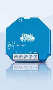
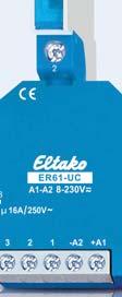
10 Switching Relay ER61-UC, Impulse Switch with integrated relay function ESR61NP ER61-UC 1 CO contact potential free 10A/250V AC, incandescent lamp load up to 2000W. No standby loss. For installation. 45mm long, 45mm wide, 18mm deep. Universal control voltage 8 to 230V UC. Low switching noise. By using a bistable relay coil power loss and heating is avoided even in the on mode. The relay contact can be open or closed when putting into operation. It will be synchronised at first operation. This relay is not suitable to feed back the switching voltage signal of a dimmer switch. Use only relays ESR12DDX-UC, ESR12NP-230V+UC or ESR61NP-230V+UC for this purpose. The electronics does not have an internal power supply and therefore no standby loss. The microcontroller is activated when the control contact closes. This switches the bistable relay to the correct direction. The bistable relay switches back either when the control contact opens or when the control voltage falls. ER61-UC 1 CO 16A EAN ,60 /pc. ESR61NP-230V+UC Function rotary switches Standard setting ex works. Side view 1 NO contact not potential free 10A/250V AC, incandescent lamp load up to 2000W. Off delay impulse switch with switch-off early warning and pushbutton permanent light switchable. Standby loss 0.7 watt only. For installation. 45mm long, 45mm wide, 18mm deep. Zero passage switching to protect contacts and lamps. This prolongs in particular the lifetime of energy saving lamps. By using a bistable relay coil power loss and heating is avoided even in the on mode. The switched consumer may not be connected to the mains before the short automatic synchronisation after installation has terminated. Control voltage 230V. In addition electrically isolated universal control voltage from 8 to 230V UC. Supply voltage and switching voltage 230V. Very low switching noise. Variable time range up to 120 minutes in the function ESV. At the control input pushbuttons with a glow lamp current up to 50mA can be connected. In case of a power failure the system is disconnected in a preset sequence. If the timing period is set to minimum in the function ESV, the release delay is switched off. The standard impulse switch function ES is then set. The function ER is selectable. If the function ER is selected a glow lamp current is not permitted. Only the control input A1- A2 should be used. When set to the function ER this device is suitable to feed back the switching voltage signal of a dimmer switch. If switch-off early warning function is switched on, the light starts flickering approx. 30 seconds before time-out. This is repeated three times at decreasing time intervals. If the permanent light function is switched on, the function can be activated by pressing the push-button for longer than 1 second. This function switches off automatically after 2 hours or by pressing the push-button for longer than 2 seconds. If both switch-off early warning function and permanent light by pushbutton are set, the switch-off early warning function is activated before switching off the permanent light ESR61NP-230V+UC 1 N0 10A EAN ,60 / pc.

11 Multifunction Impulse Switch with integr. relay function ESR61M ESR61M - UC Function rotary switches Standard setting ex works. Side view 1+1 NO contacts potential free 10A/250V AC. Incandescent lamp load up to 2000W. No standby loss. For installation. 45mm long, 45mm wide, 32mm deep. Universal control voltage 8 to 230V UC. No permanent power supply necessary, therefore no standby loss. By using bistable relays coil power loss and heating is avoided even in the on mode. The switched consumer may not be connected to the mains before the short automatic synchronisation after installation has terminated. The functions of the second rotary switch are preselected using the rotary switch ES/ER. The setting ER selects the function in brackets. 10 different functions are selectable. 2S = Impulse switch with 2 NO contacts (2R) = Switching relay with 2 NO contacts WS = Impulse switch with 1 NO contact and 1 NC contact (WR) = Switching relay with 1 NO contact and 1 NC contact SS1 = Impulse multi circuit switch 1+1 NO contacts for switching sequence 0 - contact 1(1-2) - contact 2 (3-4) - contacts (RR) = Switching relay (closed-circuit current relay) with 2 NC contacts SS2 = Impulse multi circuit switch 1+1 NO contacts for switching sequence 0 - contact 1 - contacts contact 2 (EW) = Impulse relay for fleeting NO contact with 1 NO contact and 1 NC contact, wiping time 1 sec GS = Impulse group switch 1+1 NO contacts for switching sequence 0 - contact contact 2 (GR) = Group relay 1+1 NO contacts (relay with alternating closing contacts) This relay is not suitable to feed back the switching voltage signal of a dimmer switch. Use only relays ESR12DDX-UC, ESR12NP-230V+UC or ESR61NP-230V+UC for this purpose. The electronics does not have an internal power supply and therefore no power is consumed in any contact position. A control current flows only during a short control impulse of 0.2 seconds. This activates the microcontroller, reads the last switching state from the non-voltage memory, switches the bistable relay to its opposite state accordingly and rewrites the new switching state to memory. ESR61M-UC N0 10 A EAN ,80 /pc.
12 Isolating Relay ETR61NP ETR61NP-230V 1 NO contact not potential free 10A/250V AC. With window contact. Standby loss 0.5 watt only. For installation. 45mm long, 45mm wide, 18mm deep. Control input with internally produced low voltage 24V DC. With an isolating transformer electrically isolated from power supply and make contact (PELV). Therefore no external low voltage power supply necessary. With 2 L terminals and 2 N terminals for an easy and quick installation. Power supply 230V ETR61NP-230V 1 N0 10 A EAN ,60 /pc.
 so it can be switched on only if the window is open. For installation. 45mm long, 45mm wide, 18mm deep.")
13 Isolating Relay ETR61NP with Window Contact FK ETR61NP-230V+FK 1 NO contact not potential free 10A/250V AC. With window contact. Standby loss 0.5 watt only. The power supply of an extractor hood is connected by a window contact (NO if window open) so it can be switched on only if the window is open. For installation. 45mm long, 45mm wide, 18mm deep. Control input with internally produced low voltage 24V DC. With an isolating transformer electrically isolated from power supply and make contact (PELV). Therefore no external low voltage power supply necessary. With 2 L terminals and 2 N terminals for an easy and quick installation. Power supply 230V. The enclosed window contact consists of a Reed relay with terminals and a solenoid. The NC contact opens when the solenoid approaches closer than 25mm. The disconnection relay ETR61NP is connected to terminals T1 and T2. Power supply to the extractor only cuts in when the window is open. ETR61NP can be wired in the flush mounted socket behind the socket for the extractor. Mounting the window contact FK: Lever out the inserts at the narrow end of the housing. Wire up the Reed relay and cut out the cable entry on the housing. Affix the two housings in parallel maximum 15mm apart and also screw if necessary. In the longitudinal direction the solenoid may be twisted in any direction compared to the Reed relay Window contact FK Reed relay and solenoid each 54x12x10mm ETR61NP-230V 1 N0 10 A EAN ,10 / pc. FK Window contact FK Window contact The window contact as described above is also supplied as individual (accessory) item. Reed relay with 1 NO contact, switching capacity 5W or VA. Switching voltage max. 175V UC. Reed relay and solenoid each 54x12x10mm FK window contact EAN ,80 /pc.
14 Technical Data Electronic Switching Relays, Control Relays and Coupling Relays Contacts ESR12NP- ESR12DDX-UC b), ER12DX-UC a), 230V+UC a) ER UC a), ER UC a), ER UC a), ER UC a) ESR61NP-230V+UC b) ESR61M-UC a) ETR61NP-230 V, ER61-UC a) KR09-12 V UC, -24 V UC, -230 V Contact material/contact gap AgSnO 2 /0.5mm Spacing of control connections/contact 3mm 6 mm 6 mm, ER61: 3mm 6mm Spacing of control connections C1-C2 or A1-A2/contact 6mm 6mm ESR61NP+M: 6mm -- Test voltage contact/contact ESR12DDX: 4000V ER12-200/110: 2000V ESR61M: 2000V Test voltage control connections/contact Test voltage C1-C2 or A1-A2/contact 2000 V 4000 V 4000V V ESR61NP+M+ETR61NP: 4000V 4000 V Rated switching capacity 16 A/250 V AC 16 A/250 V AC 4) 10 A/250 V AC 6A/250V AC Incandescent lamp and halogen lamp load 1) 230 V, I on 70A /10 ms 2300 W 2000 W 2000 W 500 W Fluorescent lamp load with KVG* in leadlag circuit or non compensated 1000 VA 1000 VA 1000 VA 600 VA Fluorescent lamp load with KVG* shunt-compensated or with EVG* 500 VA 500 VA 500 VA 300 VA 15x 7 W Ion <_ 70A/ 10ms 2) Ion <_ 70A/ 10ms Compact fl uorescent lamps with EVG* 52W 10x 20 W and energy saving lamps ESL When using DX types: ESR61NP: 15x7W, 3) 5) 15x7W, 10x20W 10x20W 5) 230 V LED lamps up to 200 W 5) up to 200 W 5) up to 200 W 5) up to 50 W 5) Max. switching current DC1: 12 V/24 V DC 8 A not ESR: 8A 6 A Life at rated load, cos = 1 or for incandescent lamps 1000 W at 100/h >10 5 >10 5 >10 5 >10 5 Life at rated load, cos = 0.6 at 100/h > 4 x10 4 > 4 x10 4 > 4 x Max. operating cycles 10 3 /h 10 3 /h 10 3 /h 10 4 /h Contact position indication LED (not series 61) Maximum conductor cross-section series 12: 6 mm 2 (3-fold terminal 4mm 2 ), series 61: 4mm 2 Two conductors of same cross-section series 12: 2.5mm 2 (3-fold terminal 1.5mm 2 ), series 61: 1.5mm 2 Screw head series 12: slotted/crosshead, pozidriv, series 61: slotted/crosshead Type of enclosure/terminals series 12: IP50 / IP20, series 61: IP30 / IP20 Electronics Time on 100% 100% 100% 100% Max./min. temperature at mounting location +50 C/-20 C +50 C/-20 C +50 C/-20 C +50 C/-20 C Stand by loss (active power) 0.5 W ; ESR12DDX: 0.4W Control current 230 V control input local ±20% Control current universal control voltage all control voltages ma ± 20% Control current at 8/12/24/230V (<10s) ma ± 20% Max. parallel capacitance (approx. length) of control lead at 230 V AC Compliance with: EN , EN and EN ; ESR61NP: 0.7W, ETR61NP: 0.5W 10 ma 10 ma, ER61 and ESR61M: 4 (not ESR12DDX) ER61: 2, ESR61M:4 2/4/9/5(100) ES: 0,3μF (1000 m) ER: 3nF (10 m) C1-C2: 15nF (50 m) only ESR12DDX: 2/3/7/3(50)mA 0,06 μf (200 m) ESR12DDX: 0,3μF (1000 m) only ESR61NP: 2/4/9/5(100) /15/10/11 only ETR61NP: 10mA/24V DC 0,06μF (200m) 0.06 μf (200m) * EVG = electronic ballast units; KVG = conventional ballast units a) Bistable relay as relay contact. The relay contact can be open or closed when putting into operation. It will be synchronised at fi rst operation. b) Bistable relay as relay contact. The switched consumer may not be connected to the mains before the short automatic synchronisation after installation has terminated. 1) For lamps with 150W max. 2) A 40-fold inrush current must be expected for electronic ballast devices. For steady loads of 1200W or 600W use the current limiting relay SBR12 or SBR61. See chapter 14, page ) When using DX types close attention must be paid that zero passage switching is activated! 4) For ER maximum current across both contacts 16A for 230V. 5) Usually applies for dimmable energy saving lamps and dimmable 230V LED lamps. Due to differences in the lamps electronics, there may be a restriction on the maximum number of lamps; especially if the connected load is very low (for 5W-LEDs).
Electronic impulse switches the silent revolution
 12 Electronic impulse switches the silent revolution 12 Electronic impulse switches Selection table electronic impulse switches 12-2 Impulse switch ES12DX 12-3 Impulse switch ES12-200 12-4 Impulse switch
Selection tables Command devices E 250 latching relays
 E 50 latching relays E 50 E 50 Latching relays Allow switching of the contacts in response to each pulse sent to the coil via the normally open pushbuttons. Their high performance in the single or multi-point
13 SERIES. Electronic step relays A
 13 Electronic step relays 10-16 A 13 13.81 - Electronic step relay - Rail mount - 1 Pole 13.91 - Electronic step relay and timing step relay Switch box mount - 1 Pole Fixed time (10 minutes) timing function
Electronic step, call/reset and monostable relays
 Electronic step, call/reset and monostable relays W/C Call and reset switches for bathrooms Bathrooms lighting control Bedroom light control Living room light control Office lighting control SЕRIES FINDER
650 PHOENIX CONTACT Courtesy of Power/mation Energy Lane, Saint Paul, MN
 650 PHOENIX CONTACT Monitoring relays, timer relays, function blocks The requirements pertaining to safety and system availability are constantly increasing regardless of the industry. Processes are becoming
ABB. Other modular devices Command devices. Command. MDRCs. Contents
 ABB Other modular devices MDRCs Command Contents E 59 installation relays... /9 E 00i switches... /9 E 6/, E 80/ switches... /96 E 50 latching relays... /97 E 60 latching relays... /0 E 0 switches... /05
Modular step relays 16 A
 Automation for blinds, grilles and shutters Lighting control in corridors (for hotels, offices and hospitals) Bedroom light control Living room light control SЕRIES FINDER reserves the right to alter characteristics
Smart-house Dimmer Power dimmer up to 500W Type SH2D500W230
 Smart-house Dimmer Power dimmer up to 500W Type SH2D500W230 Universal dimmer switch for R, L, C up to 500W and LED loads Automatic load detection for L, R, C loads Integrated heat sink for temperature
IMPULSE SWITCH, REMOTE SWITCH
 W REMOTE SWITCH STELLA W SCHRACK INFO Low switching noise Energy saving function 0.5 30 minutes High switching capacity, 80 A start-up peak LED display LQ540000 W APPLICATIONS 220 The ideal solution for
13 Series - Electronic step relays A. Features SERIES
 Series - Electronic step relays 10-16 A SERIES Features.81.91.81 - Electronic step relay - Rail mount - 1 Pole.91 - Electronic step relay and timing step relay Switch box mount - 1 Pole Fixed time (10
Instruction manual. art Installation manual
 Instruction manual art. 01521 Installation manual Contents GENERAL FEATURES AND FUNCTIONALITY from page 4 ETS PARAMETERS AND COMMUNICATION OBJECTS from page 6 COMMUNICATION OBJECTS GENERAL FEATURES AND
Catalog 200 Contactors up to 115 A Motor Starters up to 55 kw 03/2009
 Catalog 00 Contactors up to 5 A Motor Starters up to 55 kw 03/009 Kraus & Naimer The development of the Blue Line rotary switch, contactor and motor starter product ranges is based on more than hundred
13 Series - Electronic step relays A. Features Residential applications
 13 13 Series - Electronic step relays 10-16 A Features 13.81 13.91 13.81 - Electronic step relay - Rail mount - 1 Pole 13.91 - Electronic step relay and timing step relay Switch box mount - 1 Pole Fixed
Step relays 10 A SЕRIES. Lighting control in corridors (for hotels, offices and hospitals) Bedroom light control. Living room light control
 Bedroom light control. Living room light control") Lighting control in corridors (for hotels, offices and hospitals) Bedroom light control Living room light control SЕRIES FINDER reserves the right to alter characteristics at any time without notice. FINDER
Lighting control in corridors (for hotels, offices and hospitals) Bedroom light control Living room light control SЕRIES FINDER reserves the right to alter characteristics at any time without notice. FINDER
PIR6WT-1Z interface - time relays
 1 9-functions electronic time relays compliance with standard PN-EN 612-1 Time relay PIR6WT-1Z consists of: - universal socket with electronic PI6WT-1Z with screw terminals, - changeover relay RM699V,
Radio bus system Radio-universal dimming actuator, 1-gang. 1 Safety instructions. 2 Device components. Order-No. : Operating instructions
 Order-No. : 1135 00 Operating instructions 1 Safety instructions Electrical equipment may only be installed and fitted by electrically skilled persons. Failure to observe the instructions may cause damage
13 Series - Electronic step/monostable & call/reset relays 8-16 A. Features
 13 Series - Electronic step/monostable & call/reset relays 8-16 A Features 13.01 13.12 13.01 - Quiet operating electronic step/ monostable relay 1 Pole output contact 13.12 - Call & Reset Relay 2 Pole
Technical data: Instabus EIB supply Voltage: YY 6 x 0.6 mm; red: bus (+) / black: bus (-)
 / black: bus (-)") Product designation: switching actuator 2fold 6A FM Design: FM (flush-mounted type) Article no.: 1057 00 ETS search path: Gira Giersiepen / Output / Binary output, 2fold / switching actuator 2fold 6A FM
Product designation: switching actuator 2fold 6A FM Design: FM (flush-mounted type) Article no.: 1057 00 ETS search path: Gira Giersiepen / Output / Binary output, 2fold / switching actuator 2fold 6A FM
CAMTO. Arc detecting relay. system. January Revised August D D1200
 NEW ARC DETECTING SYSTEM FROM Based on our experience with arc protection since 1962, has developed a new. The units are built into boxes that all fit on a 35 mm DIN-rail. All front plates are dimensioned
Switching Devices Contactors and Contactor Assemblies for Switching Motors
 Switching Devices Contactors and Contactor Assemblies for Switching Motors groups 41B, 41H / Introduction Power contactors for switching motors /5 General data /11 SIRIUS RT10 contactors, -pole,... 50
EasyclickPro. Wireless Control Systems Making light work
 EasyclickPro Wireless Control Systems Making light work EasyclickPro EasyclickPro RF system The new Easyclick generation Honeywell Easyclick wireless and battery-less solutions for lighting, shutter and
ECM3 EARTH CONTINUITY RELAY
 TECHNICAL DATASHEET ECM3 EARTH CONTINUITY RELAY Electrical Protection for Hard Rock Mines Application The ECM3 has been designed to provide earth continuity protection for cables containing pilot cores.
CableTroll 2410 PN: /03. User Manual
 CableTroll 2410 PN: 01-2410- 02/03 User Manual UG CT 2410-RMU February 2010 This document describes the installation and configuration of the RMU Fault Indicator Product no: 01-2410- 02/03 Rev. 0.1 (21.01.09)
Installation- / Monitoring Technique
 Installation- / Monitoring Technique VARIMETER Insulation fault locator RR 5887 0269248 Product Description 4-channel design The locating current generator RR 5886 in connection with the insulation fault
itl impulse relays IEC/EN itls: IEC/EN itls b Allows remote indication of its operating state (open/closed)
") DB123399 DB116619 Country approval pictograms itl, itli, itls, itlc, itlm IEC/EN 60669-2-2 itls: IEC/EN 60947-5-1 Impulse relays B106126-34 B106128-34 itl b The impulse relays are used to control, by means
DB123399 DB116619 Country approval pictograms itl, itli, itls, itlc, itlm IEC/EN 60669-2-2 itls: IEC/EN 60947-5-1 Impulse relays B106126-34 B106128-34 itl b The impulse relays are used to control, by means
luxcontrol lighting control system DALI sensors basicdim RCL DBC Control module for combination with ambient light sensor, switch and presence sensor
 basicdim RCL DBC Control module for combination with ambient light sensor, switch and presence sensor Digital control module with ambient light sensor, motion detector and switch input DALI Broadcast control
Rev ABB i-bus KNX 6151/11 U-500. Power and productivity for a better world TM
 1 73-1-7831 Rev. 01 3.2012 6151/11 U-500 Power and productivity for a better world TM Page: 1 of 31 Switching actuator 1gang with binary Inputs, FM Actuator Article-no.: 6151/11 U-500 ETS search path:
RELOG. All-or-nothing Relay
 RELOG All-or-nothing Relay Table of Content Page RELOG a system with contact components used in control engineering 3 Survey of the 'All-or-nothing relays' device program included in the RELOG system 3
*Current connection required for smooth zerocrossing switch operation
 2 2 310 317 02 LUNA LUNA 109 109 0 100, 109 0 200 110 0 100, 110 0 200 GB Assembly and operating instructions Twilight Switch Test 2 2000 LUNA 109 I:2-35 II : 35-200 III : 200-1000 min max IV:1-5klx V:
XR1 Rotor Earth Fault Relay. (May 2007) Manual XR1 (Revision New)
 Manual XR1 (Revision New)") XR1 Rotor Earth Fault Relay (May 2007) Manual XR1 (Revision New) Woodward Manual XR1 GB Woodward Governor Company reserves the right to update any portion of this publication at any time. Information provided
XR1 Rotor Earth Fault Relay (May 2007) Manual XR1 (Revision New) Woodward Manual XR1 GB Woodward Governor Company reserves the right to update any portion of this publication at any time. Information provided
Miniature circuit-breakers S 280 UC series. System pro M. Technical data
 Technical data 11 Robbie Rd. / Avon, MA 02322 T:(508)513-1000 F:(508)513-1100 70 Ernest St. / Providence, RI 02905 T:(401)781-7100 www.controllerservice.com System pro M Prior to connection of aluminum
luxcontrol lighting control system DSI sensors smartdim SM lp Control module for combination with ambient light sensor, switch or presence sensor
 Control module for combination with ambient light sensor, switch or presence sensor Product description Digital DSI control module (luminaire installation unit) for daylight control, motion detector and
Reliably switch high powers and specific loads Our TERMSERIES and D-SERIES products are proven in practice Let s connect.
 Reliably switch high powers and specific loads Our TERMSERIES and D-SERIES products are proven in practice Let s connect. Relay modules and solid-state relays You are looking for suitable relays and solid-state
PSR-SCP- 24DC/ESD/5X1/1X2/300
 Extract from the online catalog PSR-SCP- 24DC/ESD/5X1/1X2/300 Order No.: 2981428 Safety relay with adjustable delay time 0-300 s, screw version Commercial data EAN 4017918975227 Pack 1 pcs. Customs tariff
Sentry Digital Timers
 Sentry Digital Timers 0733s S4 Contents 1. Safety precautions 2. General rmation 3. DIN rail Installation 4. Display Layout. Programming 6. Technical Data 7. Guarantee 2 Safety precautions The connection
No-wear isolation of potentials in terminal block design
 TERMOPTO Overview No-wear isolation of potentials in terminal block design Space saving solid-state relay with PUSH IN connection technology The TERMOPTO opto modules are characterised by a particularly
This product is for use in a dry, indoor environment only. This product is not to be installed near water, liquid, or flammable materials.
 The equipment described in this manual contains high voltage. Always disconnect power to the equipment before installing, disconnecting, or servicing the product. This product is for use in a dry, indoor
KNX manual High-performance switch actuators RM 4 H FIX1 RM 8 H FIX2
 KNX manual High-performance switch actuators RM 4 H FIX1 RM 8 H FIX2 4940212 4940217 2018-10-17 Contents 1 Function description 3 2 Operation 4 3 Technical data 5 4 The FIX2 RM 8 H application programme
Modular Devices - Indicators and Push Buttons
 Modular Devices - Indicators and Push Buttons The new range of indicator lights and push buttons replaces and expands upon the whole SV range and is composed of the following three families Indicator Lights
Overview of types. Technical data
 echnical data sheet SHA-.. Multifunctional linear actuators for adjusting air dampers and slide valves in ventilation and air-conditioning systems for building services installations For air control dampers
Fibaro System Modules
 Chapter 3 Fibaro System Modules 3.1 Fibaro Dimmer FGD211 Figure 3.1: Dimmer module, FGD-211 Radio controlled light dimming module, designed to work with light sources of any type. May be connected to two-wire
Smart Dupline Wireless dimmer with energy reading Type SHJWD200WExxx
 Smart Dupline Wireless dimmer with energy reading Type SHJWD200WExxx Universal wireless dimmer up to 200 W for R, L, C load and LED lamps Wireless transmission based on IEE802.15.4 @ 2.4 GHz Automatic
Count - counters 5. Selection guide 5 XBK T81030U33E RC XBK RC XBK T60000U00M XBK T60000U11M XBK T80000U00M XBK T70000U00M 5/2
 Selection guide Count - counters Function Totalising counters Display type Mechanical LCD Font panel dimensions (h x w) in mm 0 x 0 x. 0 x 60 x Number of display digits 6 digits or 6 digits (depending
1. Contents Page. 2. Assembly, putting into operation, connection Control elements Display Factory setting Changing settings 6
 1. Contents 2 1. Contents Page 2. Assembly, putting into operation, connection 3 3. Control elements 4 4. Display 4 5. Factory setting 5 6. Changing settings 6 6.1 Time and day of the week 6 6.2 Calendar
XI1-I Time overcurrent relay. (Januar 2007) Manual XI1-I (Revision New)
 Manual XI1-I (Revision New)") XI1-I Time overcurrent relay (Januar 2007) Manual XI1-I (Revision New) Woodward Manual XI1-I GB Woodward Governor Company reserves the right to update any portion of this publication at any time. Information
XI1-I Time overcurrent relay (Januar 2007) Manual XI1-I (Revision New) Woodward Manual XI1-I GB Woodward Governor Company reserves the right to update any portion of this publication at any time. Information
SELEKTA SELEKTA 170 top2 D GB F I E P NL PL. Installation and Operating Manual Digital astronomic time switch. SELEKTA 170 top2
 2 309 081 03 SELEKTA SELEKTA 170 top2 170 0 100 0,5mm - L N 230-240V~ Installation and Operating Manual Digital astronomic time switch MENU SELEKTA 170 top2 D F I E P NL PL 1 2 3 SELEKTA 170 top2 Correct
FLEXRISE2 VERSION. 2 LEG / 2 MOTOR ELECTRIC TABLE BASE (36 to 72 ) **PATENT PENDING**
 **PATENT PENDING**") FLEXRISE2 2 LEG / 2 MOTOR ELECTRIC TABLE BASE (36 to 72 ) VERSION A INSTRUCTION MANUAL CONTENTS: FLEX-MU-2L3S-C3672-K4# FEET-ADJ-UNV-2430# **PATENT PENDING** MAX Load 265 lbs (120 KG) Equally Divided MAX
FLEXRISE2 2 LEG / 2 MOTOR ELECTRIC TABLE BASE (36 to 72 ) VERSION A INSTRUCTION MANUAL CONTENTS: FLEX-MU-2L3S-C3672-K4# FEET-ADJ-UNV-2430# **PATENT PENDING** MAX Load 265 lbs (120 KG) Equally Divided MAX
Technical Specification
 LARGEST RANGE OF IMPULSE TESTERS UP TO 100KV/100KA Technical Specification No. E-MIG0603IN2.doc revised: 20.October 2004 1 MIG Tester Type MIG0603IN2 1 MIG Tester Type MIG0603IN2 1 1.1 Introduction 1 2
Relais und Automatisierungssysteme JUST IN TIME. with the. New Generation NGG. from Schleicher NGG CATALOGUE
 JUST IN TIME with the New Generation NGG from Schleicher NGG CATALOGUE General information on the New Generation NGG Quality control 2 Norms, regulations, approvals 2 Housing system, conductor sizes 3
3 PHASE ENERGY ELECTRONIC METERS MKT & MKT2. (Code to ) INSTRUCTION MANUAL ( M / 00 A ) (c) CIRCUTOR S.A.
 INSTRUCTION MANUAL ( M / 00 A ) (c) CIRCUTOR S.A.") 3 PHASE ENERGY ELECTRONIC METERS MKT & MKT2 (Code 7 71 071 to 7 71 083) INSTRUCTION MANUAL ( M 981 200 / 00 A ) (c) CIRCUTOR S.A. ----- MKT- MKT2 - ELECTRONIC METERS -------- M-981 200 --- Page Nº 2 3
3 PHASE ENERGY ELECTRONIC METERS MKT & MKT2 (Code 7 71 071 to 7 71 083) INSTRUCTION MANUAL ( M 981 200 / 00 A ) (c) CIRCUTOR S.A. ----- MKT- MKT2 - ELECTRONIC METERS -------- M-981 200 --- Page Nº 2 3
DZD 92 L. Wiring diagram. Time domains. Function. Dimensional drawing. Indicators. Accessories
 DZD 92 L Multi-Function - Multi-domain time relay Mono voltage 8 Functions Setting range 0.05 s to 100 h subdivided into 7 time domains 1 immediate-action and 1 time contact or 2 time contacts (adjustable)
MasterINTERFACE 39 Series - Relay interface modules
 Common features Space saving 6.2 mm wide Connections for 16-way jumper link Integral coil indication and protection circuit Secure retention and easy ejection by plastic clip Dual screw head (blade+cross)
XR1 Rotor Earth Fault Relay. Manual XR1 (Revision C)
") XR1 Rotor Earth Fault Relay Manual XR1 (Revision C) Woodward Manual XR1 (EN) Woodward Governor Company reserves the right to update any portion of this publication at any time. Information provided by
XR1 Rotor Earth Fault Relay Manual XR1 (Revision C) Woodward Manual XR1 (EN) Woodward Governor Company reserves the right to update any portion of this publication at any time. Information provided by
Accessories useful helpers about the Eltako installation
 Accessories useful helpers about the Eltako installation 22 22 Accessories wireless and others WET.PROTECT WP50 22-2 Wireless Powernet phase coupler FPP12 22-2 Multimedia (Sonos) EnOcean gateway APPModule
ISOMETER IRDH575. Approvals
 Insulation monitoring device for unearthed AC, DC and AC/DC systems (IT systems) with control and display function for EDS insulation fault location systems IRDH575_D00089_02_D_XXEN/09.2018 Insulation
1. Function. Universal dimming actuator REG-K/2x230/ 300 W. Universal dimming actuator REG-K/230/ 500 W. Universal dimming actuator REG-K/230/ 1000 W
 L L N N on error RUN 1 2 3 4 KNX EIB 1 1 1 1 Chapter 9: Dimming actuators/control units Chapter 9:Dimming actuators/control unitsart. no.6493xxas of 10/079.2Universal dimming actuators Universal dimming
PCA ECO lp Y, W T8 fluorescent lamps
 T8 PCA ECO lp Y, 58 W T8 fluorescent lamps Product description Processor-controlled ballast with y inside Noise-free precise control via DSI signal, switchdim or corridorfunction CELMA energy class A1
12/2 Product overview. 12/3 7KT1 14, 7KT1 53 E-counters. 12/9 7KT1 11, 7KT1 12 digital measuring devices. 12/11 7KT1 0 analog measuring devices
 BETA Measuring /2 Product overview /3 7KT1 14, 7KT1 53 E-counters /9 7KT1 11, 7KT1 digital measuring devices /11 7KT1 0 analog measuring devices / 7KT5 8 time and pulse counters /14 7KT5 5, 7KT5 6 time
EIB/KNX Switch Actuators. User manual
 EIB/KNX Switch Actuators User manual IT KNT 004 IT KNT 012 Tel.: +34943627988 E-mail: knx@dinuy.com Web: www.dinuy.com Contents 1. Introduction --------------------------------------------------------------------------------------------------------------
FL ballasts Electronic dimming. PCA T5 ECO lp Y, 3x14/24 W and 4x14/24 W ECO T5
 T5 PCA T5 ECO lp Y, x1/ W and x1/ W ECO T5 Product description Processor-controlled ballast with y inside Highest possible energy class CELMA EEI = A1 BAT 1 Noise-free precise control via DSI signal, switchdim
FL ballasts Electronic dimming. PCA T8 ECO lp Y II, W ECO T8
 T8 PCA T8 ECO lp Y II, 18 58 W ECO T8 Product description Processor-controlled ballast with y II inside Highest possible energy class CELMA EEI = A1 BAT 1 Noise-free precise control via DALI or DSI signal,
STX Stair lighting controller.
 Stair lighting controller STX-1792 STX-1792 controller is used to control stairs lighting dynamically. The backlight is switched on with the subsequent steps, depending on the motion directions: ascending
Micro Contactors. Micro Contactor Relays 10. Micro Contactors 11. Micro Contactors With Solder Pins 12. Coil voltages 12. Micro Reversing Contactor 13
 Micro Contactor Relays 10 Micro Contactors 11 Micro Contactors With Solder Pins 12 Coil voltages 12 Micro Reversing Contactor 13 Technical Data 14 Dimensions 18 D946E 9 Micro Contactor Relays 4-pole AC
Not for Reproduction
 1 ADVANCE PRODUCT SERVICE INFORMATION SUBJECT: OPERATING PROCEDURES FOR EXTECH DIGITAL MULTIMETER No: #66 DATE: 05/31/2010 MODELS: 19602 DIGITAL MULTIMETER A digital multimeter is necessary for electrical
21 VA (l max 20 5 ms) Connection Cable 1 m, 4 x 0.75 mm 2 Functional data Factory settings Variable Setting Torque Inhibiting torque
 Connection Cable 1 m, 4 x 0.75 mm 2 Functional data Factory settings Variable Setting Torque Inhibiting torque") echnical data sheet GK4A- Communicative SuperCap rotary actuator with emergency setting function and extended functionalities for adjusting air dampers in ventilation and air-conditioning systems for building
echnical data sheet GK4A- Communicative SuperCap rotary actuator with emergency setting function and extended functionalities for adjusting air dampers in ventilation and air-conditioning systems for building
FL ballasts Electronic dimming. PCA T8 ECO lp Y, 3x18 W and 4x18 W ECO T8
 T8 PCA T8 ECO lp Y, x18 W and x18 W ECO T8 Product description Processor-controlled ballast with y inside Highest possible energy class CELMA EEI = A1 BAT 1 Noise-free precise control via DSI signal, switchdim
Installation / Monitoring Technique
 Installation / Monitoring Technique VARIMETER RCM Residual Current Monitor, Type B for AC and DC Systems IP 5883 0249633 IP 5883 ND 5018/035 ND 5018/030 According to IEC/EN 62 020, VDE 0663 For AC and
AT-SL-DDR & AT-SL-DDR-SA
 AT-SL-DDR & AT-SL-DDR-SA Product Guide Slim-line RF DALI/DSI + relay controller Overview The AT-SL-DDR and AT-SL-DDR-SA are wireless controllers with two output channels capable of controlling incandescent,
XUA1 AC Voltage and phase balance relay. (August 1996) Manual XUA1 (Revision New)
 Manual XUA1 (Revision New)") XUA1 AC Voltage and phase balance relay (August 1996) Manual XUA1 (Revision New) Woodward Manual XUA1 GB Woodward Governor Company reserves the right to update any portion of this publication at any time.
XUA1 AC Voltage and phase balance relay (August 1996) Manual XUA1 (Revision New) Woodward Manual XUA1 GB Woodward Governor Company reserves the right to update any portion of this publication at any time.
Technical Specification
 LARGEST RANGE OF IMPULSE TESTERS UP TO 100KV/100KA Technical Specification E-MIG1203CWG revised: 22. June 2003 1 MIG Tester Type MIG1203CWG 1 MIG Tester Type MIG1203CWG 1 1.1 Introduction 1 2 General 2
XU2-AC AC voltage relay. (Februar 1997) Manual XU2-AC (Revision New)
 Manual XU2-AC (Revision New)") XU2-AC AC voltage relay (Februar 1997) Manual XU2-AC (Revision New) Woodward Manual XU2-AC GB Woodward Governor Company reserves the right to update any portion of this publication at any time. Information
XU2-AC AC voltage relay (Februar 1997) Manual XU2-AC (Revision New) Woodward Manual XU2-AC GB Woodward Governor Company reserves the right to update any portion of this publication at any time. Information
Electronic Circuit Breaker ESS20-0..
 Description Electronic circuit breaker type ES-0.. is designed to ensure selective disconnection of individual loads in systems which are powered by a DC 4 V switch-mode power supply. DC 4 V power supplies,
Manual triggering of the adaption by pressing the «Adaption» button or with the PC-Tool
 echnical data sheet SMA--P Multifunctional damper actuator for adjusting air dampers in ventilation and air-conditioning systems for building services installations For air dampers up to approx. m orque
Electronic timer CT-AWS Impulse-OFF with 1 c/o contact Data sheet
 2CDC 251 121 F0004 1 5 2 4 3 6 Characteristics Single-function impulse-off timer One device includes 10 time ranges, from 0.05 s to 300 h, for the adjustment of the pulse time Remote potentiometer connection
Radio motion detector comfort 1.1 m/2.2 m quicklink Order number
 Radio motion detector comfort 1.1 m/2.2 m quicklink Order number 8534 51.. Operating instructions 1. Safety instructions Electrical equipment may only be installed and assembled by a qualified electrician
PHASED OUT. Digital dimmable ballasts for fluorescent lamps EXCEL series. PCA TCL EXCEL one4all lp Y, 55 W Compact and T5c fluorescent lamps
 EXCE series Product description Processor-controlled ballast with y inside oise-free precise control via DSI signal, switchdim, corridorfuctio or I I-MEMORY Extended I commands OEM-specific reserved memory
Electronic timer CT-ERS ON-delayed with 2 c/o contacts Data sheet
 1SVR 430 103 F0200 CT-ERS 1 7 2 6 5 4 8 3 1 10 selectable time ranges, from 0.05 s to 300 h 2 Potentiometer with direct reading scale for the fine adjustment of the time delay 3 Sliding switch to set the
Technical data Insulation fault location system Device components
 Technical data Insulation fault location system Device components Device type DS470-12 PRC470 Insulation coordination acc. to IC 60664-1: Rated insulation voltage AC 250 V AC 250 V AC 500 V Rated impulse
Panasonic products. SIngle function-multirange Multifunction single-range Multifunction-multirange. Precise High quality.
 Panasonic products SIngle function-multirange Multifunction single-range Multifunction-multirange Precise High quality Reliable Robust Table of Contents General Information Timers Timers Chart Overview
MODEL: 47LV. Digital Panel Meters 47 Series
 Digital Panel Meters 7 Series DC INPUT DIGITAL PANEL METER ( ½ digit, LED display type) Functions & Features ½ digit DC input digital panel meter /8 DIN size Moving average function to suppress the display
ISOSCAN EDS460-DG. Insulation fault locator for DC IT systems with high system leakage capacitances
 ISOSCAN Insulation fault locator for DC IT systems with high system leakage capacitances _D00108_00_D_XXEN/05.2015 ISOSCAN Insulation fault locator for DC IT systems with high system leakage capacitances
Installation and Operating Instructions Differential pressure transmitter for potentially explosive areas. MG-1000-EEx USAGE STRUCTURE AND DESIGN
 Installation and Operating Instructions Differential pressure transmitter for potentially explosive areas Mimablad: 176GB/1999-10-25 Ersätter: MG-1000-EEx USAGE MG-1000-EEx is suitable for use in measurement
Modular equipment. Presentation, standards. Standard contactors TeSys GC
 Presentation, standards Standard contactors TeSys GC Presentation TeSys GC contactors are designed for use in modular panels and enclosures. These contactors feature: b Easy installation v quick clip-on
AT-SL-DDR & AT-SL-DDR-SA
 Product Guide AT-SL-DDR & AT-SL-DDR-SA Slim -line RF DALI/DSI + relay controller Overview The AT-SL-DDR andat-sl-ddr-sa are wireless controllers with two output channels capable of controlling incandescent,
MCU-10. Display. Adjustments. Analogue Output, Measuring. Analogue Output, Setpoint. Standard Process Signal. LED Indication. LCD Display.
 Introduction & Selection Guide INTRODUCTION The Brodersen monitoring relays are high quality products incorporating up-to-date circuit design together with modern, efficient components to ensure a long
Device manual Multifunction display and evaluation system FX 360. Mode/Enter
 Device manual Multifunction display and evaluation system FX 360 7390275 / 08 07 / 2009 Mode/Enter Set Safety instructions This manual is part of the unit. It contains texts and diagrams for the correct
XUA1 - AC Voltage and phase balance relay
 XUA1 - AC Voltage and phase balance relay Contents 1. Applications and features 2. Design 3. Function 3.1 Voltage supervision 3.2 Unbalanced voltage supervision 4. Operation and settings 4.1 Setting of
The power in relays and timers since Catalogue
 The power in relays and timers since 1954 2012 Catalogue PCB relays Industrial relays Relay interface modules Sockets and accessories Timers Monitoring relays Energy meters Surge protection devices Industrial
Protection and safety SQZ3 phase and sequence relay
 SQZ3 phase and sequence relay Supply voltage [Vn] 400 V a.c. Frequency [Hz] 0/60 SQZ3 2CSC4001F0201 Contact type [A] 1 CO, 20 V, 10 A (cos =1) safety switching Minimum voltage adjustment trimmer [%] 100
DM-46 Instruction Manual
 Auto Meter Products Inc. Test Equipment DM-46 Instruction Manual Automotive Multimeter and Inductive Amp Probe The DM-46 is the auto industry s answer to pocket portability in a 20 2650-1552-00 3/8/11
REV-201М OPERATING MANUAL MULTIFUNCTIONAL TWO-CHANNEL TIME DELAY RELAY. «NOVATEK-ELECTRO» Ltd Intelligent industrial electronics
 Ltd Intelligent industrial electronics MULTIFUNCTIONAL TWO-CHANNEL TIME DELAY RELAY OPERATING MANUAL Review the Operating manual before using the unit. www.novatek-electro.com Store the unit in the operating
MasterINTERFACE 39 Series - Relay interface modules
 MasterINTERFACE 39 Series - Relay interface modules Common features Space saving 6.2 mm wide Connections for 16-way jumper link Integral coil indication and protection circuit Secure retention and easy
Dipl.-Ing. W. Bender GmbH & Co. KG Londorfer Str Grünberg Tel.: Fax:
 Dipl.-Ing. W. Bender GmbH & Co. KG Londorfer Str. 65 35305 Grünberg Tel.: 06401 807-0 Fax: 06401 807-259 Insulation fault locator Insulation fault locator for DC IT systems with high system leakage capacitances
relais A mark Relay modules
 Relay modules relais Introduction to relay technology Modular DIN rail mounted relays Plug-in DIN rail mounted relays Multiple chassis mounted relays Timer relays The relay modules offer features such
HG RELAYS 20 AMP POWER RELAY FEATURES SPECIFICATIONS
 20 AMP POWER RELAY RELAYS a 3 1.4 5 a.0 50.0 1.99 8.0 2. FEATURES Large capacity 20 A V AC resistive and 1.5 kw 3 phase 220 V AC motor loads High contact reliability after long use Usable with direct soldering,
Electrical data Nominal voltage AC/DC 24 V Nominal voltage frequency
 echnical data sheet SVK24A--PC Communicative globe valve actuator with emergency control function for 2-way and 3-way globe valves Actuating force 1500 N Nominal voltage AC/DC 24 V Control modulating,
Modular. Modular. devices
 Modular Modular devices Modular Devices Indicators and Push Buttons The new range of indicator lights and push buttons replaces and expands upon the whole SV range and is composed of the following three
XF2 Frequency Relay. Manual XF2 (Revision A)
") XF2 Frequency Relay Manual XF2 (Revision A) Woodward Manual XF2 GB Woodward Governor Company reserves the right to update any portion of this publication at any time. Information provided by Woodward Governor
XF2 Frequency Relay Manual XF2 (Revision A) Woodward Manual XF2 GB Woodward Governor Company reserves the right to update any portion of this publication at any time. Information provided by Woodward Governor
Railway applications. Relays Time relays Monitoring relays Sockets
 Railway applications Relays Time relays Monitoring relays ockets Devices for superior requirements Reliable and afe olutions for Railway and Transportation Applications olutions for the transport market
Thermostat P. Thermostats Electronic room thermostat with clock for thermal actuators
 Thermostat P Thermostats Electronic room thermostat with clock for thermal actuators IMI HEIMEIER / Thermostats & Actuators / Thermostat P Thermostat P The Thermostat P room temperature controller is used