For this example, the required filter order is five, to theoretically meet the specifications. This then equates to the required susceptances as:
|
|
|
- Sara Morgan
- 5 years ago
- Views:
Transcription


1
 are: θ 1 =θ 5 =2.2807 θ 2 =θ 4 =2.5825 θ 3 =2.")
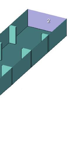
2 For this example, the required filter order is five, to theoretically meet the specifications. This then equates to the required susceptances as: = = = Likewise, the electrical lengths of the cavities at f 0 (in rad) are: θ 1 =θ 5 = θ 2 =θ 4 = θ 3 =2.654 The physical lengths are easily determined by the known formula of the wavelength in a rectangular waveguide: Here λ 0 is the free space wavelength and f c is the cutoff frequency of the guide. As for the propagation constant, it is available directly as a measurement inside the Microwave Office software. The measurement K_Port is there as well and found under the Electromagnetic measurement category. Working through the necessary formulas, the physical lengths are determined to be: =18 mm =20.4 mm =20.96 mm The next step is to determine the iris opening. This must be mapped to a susceptance at f 0. For this, one iris is considered and the opening is parameterized.


3 Determination of Susceptance Referring to Figure 3, Port 1 is de-embedded to the plane of the iris. Port 2 is terminated with Z 0 of the waveguide, so there is no reflection from Port 2. Thus, S 11 is due to iris susceptance alone. Figure 3: Determination of susceptance. A pure susceptance, or shunt inductance, draws a trajectory on the constant conductance circle on a Smith chart, as shown in Figure 4. It is expected to see such behavior at f 0 as a function of the iris opening. Figure 4: A pure susceptance draws a trajectory on the constant conductance circle on a Smith chart, indicated by the red arrow. Single Parameterized Iris Analyst allows geometry parameterization such that the parameters are exposed and controlled from within Microwave Office circuit design framework. Figure 5 shows that the local variables in Microwave Office on the left side are used as parameters of the 3D model in the middle, which accordingly generates the geometry on the right. Figure 5: Parameters for geometry parameterization are exposed and controlled by the 3D editor from within Microwave Office.

4 When looking at the S 11, it is important to use the generalized S (GS) measurement under the Electromagnetic category because the ports are terminated by the dispersive characteristic impedance of the WG rather than 50 ohms. The susceptances can then be evaluated at f 0 using output equations as depicted in Figure 6. Figure 6: The susceptance at f 0 can be evaluated using output equations. Figure 7 shows the nearly perfect result of the susceptance versus the iris opening. =1.0402=3.87 mm =2.7404=5.52 mm =3.7714=6.01 mm Figure 7: The nearly perfect results of the susceptance versus the iris opening. Final Model and Fine Tuning Having determined the dimensions of the filter, the full filter model can now be constructed. has been parameterized to and W 1 to W 3, simplifying the implementation of the design equations (Figure 8). Figure 8: Implementation of the design equations with parameterized to and W 1 parameterized to W 3.
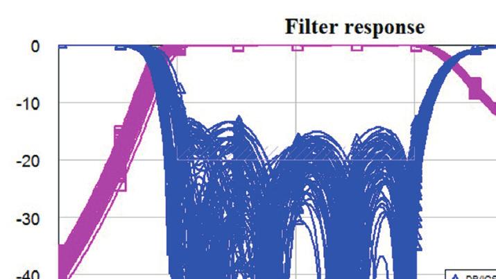
 is necessary at 1080 MHz centered at 9129 MHz.")
5 The results of the first attempt, shown in Figure 9, are very good. However, the irises are not ideal they have finite thickness, so the cavities are not ideal either. Figure 9: Results of first attempt at parameterization. The bandwidth is 926 MHz with the center at 8871 MHz, so a nominal redesign (optimization/tuning) is necessary at 1080 MHz centered at 9129 MHz. With the new f 0 at GHz, the results of the first redesign iteration, as shown in Figure 10, are: =17.37 mm =19.68 mm =20.24 mm =1.007=3.87 mm Figure 10: First redesign of filter. =2.63=5.50 mm =3.623=6.00 mm This iteration produces a band of GHz to GHz. The BW is then squeezed 34 MHz and the frequency is moved up 60 MHz for the second design iteration, resulting in the following, as shown in Figure 11. =17.31 mm =19.59 mm =20.13 mm Figure 11: The second redesign. =1.061=3.98 mm =2.811=5.64 mm =3.866=6.12 mm The second iteration produces a band of GHz to GHz and RL better than 19.5 db over the band. Using design equations, the frequency can be shifted 5 MHz and the RL improved to meet the passband specification exactly (Figure 12). =17.28 mm =19.58 mm =20.13 mm Figure 12: The second correction. = 3.95 mm = 5.62 mm = 6.10 mm
6

7 Optimizing the nominal values with a resolution of 10 um, the yield can be improved to 41.5% with ±20 um tolerance. This is not good enough the tolerance has to be reduced. The yield sensitivity histograms in Figure 15 suggest a minimum tolerance: if the dimensions to ±5 um can be controlled, 100% yield can be achieved. Figure 15: Yield sensitivity histograms suggest a minimum tolerance. Having identified good nominal values, a corner analysis EM sweep can now be run where all parameters are varied at their extremes. Figure 16 shows that the RK is acceptable. Figure 16: The filter response shows that the return loss is acceptable. For the last modification, design equations are used to expand frequency limits a bit to provide a safe margin. Conclusion This application note has showcased a design example for an iris-coupled waveguide (WG) bandpass filter designed using Microwave Office circuit design software and the Analyst 3D FEM EM simulator. The passband specifications are met with =17.175, =19.515, =20.07, W 1 =3.915, W 2 =5.59, and W 3 =6.07, as shown in Figure 17. The yield is 100%, if the dimensions can be controlled to ±5 um precision. At 8 GHz and 10.5 GHz the rejection is better than db and db, respectively. References Ian Hunter: Theory and Design of Microwave Filters, Institution of Engineering and Technology, London, UK Figure 17: The passband specifications are met with L1=17.175, L2=19.515, L3=20.07, W1=3.915, W2=5.59 and W3= National Instruments. All rights reserved. A National Instruments Company, AWR, Microwave Office, National Instruments, NI, and ni.com are trademarks of National Instruments. Other product and company names listed are trademarks or trade names of their respective companies. AN-MWCMP
LTE Small-Cell Base Station Antenna Matched for Maximum Efficiency
 Application Note LTE Small-Cell Base Station Antenna Matched for Maximum Efficiency Overview When designing antennas for base stations and mobile devices, an essential step of the design process is to
Design and Matching of a 60-GHz Printed Antenna
 Application Example Design and Matching of a 60-GHz Printed Antenna Using NI AWR Software and AWR Connected for Optenni Figure 1: Patch antenna performance. Impedance matching of high-frequency components
Design of Microstrip Coupled Line Bandpass Filter Using Synthesis Technique
 Design of Microstrip Coupled Line Bandpass Filter Using Synthesis Technique 1 P.Priyanka, 2 Dr.S.Maheswari, 1 PG Student, 2 Professor, Department of Electronics and Communication Engineering Panimalar
IMPROVED BANDWIDTH WAVEGUID BANDPASS FIL- TER USING SIERPINSKI FRACTAL SHAPED IRISES
 Progress In Electromagnetics Research Letters, Vol. 36, 113 120, 2013 IMPROVED BANDWIDTH WAVEGUID BANDPASS FIL- TER USING SIERPINSKI FRACTAL SHAPED IRISES Abbas A. Lotfi-Neyestanak 1, *, Seyed M. Seyed-Momeni
Design of an Evanescent Mode Circular Waveguide 10 GHz Filter
 Application Note Design of an Evanescent Mode Circular Waveguide 10 GHz Filter Overview Ham radio operation at 10 GHz is far removed from global shortwave communication typically operating below 30 MHz.
Evaluation of Package Properties for RF BJTs
 Application Note Evaluation of Package Properties for RF BJTs Overview EDA simulation software streamlines the development of digital and analog circuits from definition of concept and estimation of required
Narrowband Microstrip Filter Design With NI AWR Microwave Office
 Narrowband Microstrip Filter Design With NI AWR Microwave Office Daniel G. Swanson, Jr. DGS Associates, LLC Boulder, CO dan@dgsboulder.com www.dgsboulder.com Narrowband Microstrip Filters There are many
Design of an Evanescent Mode Circular Waveguide 10 GHz Filter
 Design of an Evanescent Mode Circular Waveguide 10 GHz Filter NI AWR Design Environment, specifically Microwave Office circuit design software, was used to design the filters for a range of bandwidths
Narrowband Combline Filter Design with ANSYS HFSS
 Narrowband Combline Filter Design with ANSYS HFSS Daniel G. Swanson, Jr. DGS Associates, LLC Boulder, CO dan@dgsboulder.com www.dgsboulder.com Introduction N = 6 Inline, Cover Loaded, Combline Filter Single
Ceramic Waveguide Filters with Wide Spurious-Free Stopband Response
 Progress In Electromagnetics Research M, Vol. 79, 23 31, 2019 Ceramic Waveguide Filters with Wide Spurious-Free Stopband Response Sharjeel Afridi 1, *, Ian Hunter 2, and Yameen Sandhu 1 Abstract This work
Electrical Design of Narrow Band Filters. Giuseppe Macchiarella Polytechnic of Milan, Italy Electronic and Information Department
 Electrical Design of Narrow Band Filters Giuseppe Macchiarella Polytechnic of Milan, Italy Electronic and Information Department Introduction The design of a narrow band microwave filter starts with the
A Rectangular Ring Shaped Ultra-Wide Band Pass Filter Design
 A Rectangular Ring Shaped Ultra-Wide Band Pass Filter Design Pankaj Jain Shabahat Hasan Deepak Raghuvanshi Deptt. of Microwave & Milimeter Deptt. of Microwave & Milimeter Deptt. of Digital Communication
K-band Waveguide BPF Design using Agilent EMPro Anurag Bhargava Application Consultant Agilent EEsof EDA
 K-band Waveguide BPF Design using Agilent EMPro 2013 Anurag Bhargava Application Consultant Agilent EEsof EDA Filter Specifications Center Frequency (Fc): 25 GHz 3dB Bandwidth: 150 MHz Rejection: 40 db
TOPIC 2 WAVEGUIDE AND COMPONENTS
 TOPIC 2 WAVEGUIDE AND COMPONENTS COURSE LEARNING OUTCOME (CLO) CLO1 Explain clearly the generation of microwave, the effects of microwave radiation and the propagation of electromagnetic in a waveguide
Γ L = Γ S =
 TOPIC: Microwave Circuits Q.1 Determine the S parameters of two port network consisting of a series resistance R terminated at its input and output ports by the characteristic impedance Zo. Q.2 Input matching
COMPUTER-AIDED DESIGN OF Y-JUNCTION WAVE- GUIDE DIPLEXERS
 Progress In Electromagnetics Research C, Vol. 17, 203 218, 2010 COMPUTER-AIDED DESIGN OF Y-JUNCTION WAVE- GUIDE DIPLEXERS F. M. Vanin and F. Frezza Department of Information Engineering, Electronics, and
Microwave Circuits Design. Microwave Filters. high pass
 Used to control the frequency response at a certain point in a microwave system by providing transmission at frequencies within the passband of the filter and attenuation in the stopband of the filter.
Designing a Narrowband 28 GHz Bandpass Filter for 5G Applications. Presented by David Vye technical marketing director NI, AWR Groups
 Designing a Narrowband 28 GHz Bandpass Filter for 5G Applications Presented by David Vye technical marketing director NI, AWR Groups Agenda 5G Applications and Filter Requirements 5G Challenges: Performance,
Transformation of Generalized Chebyshev Lowpass Filter Prototype to Suspended Stripline Structure Highpass Filter for Wideband Communication Systems
 Transformation of Generalized Chebyshev Lowpass Filter Prototype to Suspended Stripline Structure Highpass Filter for Wideband Communication Systems Z. Zakaria 1, M. A. Mutalib 2, M. S. Mohamad Isa 3,
THE DESIGN of microwave filters is based on
 IEEE TRANSACTIONS ON MICROWAVE THEORY AND TECHNIQUES, VOL. 46, NO. 4, APRIL 1998 343 A Unified Approach to the Design, Measurement, and Tuning of Coupled-Resonator Filters John B. Ness Abstract The concept
QUASI-ELLIPTIC MICROSTRIP BANDSTOP FILTER USING TAP COUPLED OPEN-LOOP RESONATORS
 Progress In Electromagnetics Research C, Vol. 35, 1 11, 2013 QUASI-ELLIPTIC MICROSTRIP BANDSTOP FILTER USING TAP COUPLED OPEN-LOOP RESONATORS Kenneth S. K. Yeo * and Punna Vijaykumar School of Architecture,
Leveraging High-Accuracy Models to Achieve First Pass Success in Power Amplifier Design
 Application Note Leveraging High-Accuracy Models to Achieve First Pass Success in Power Amplifier Design Overview Nonlinear transistor models enable designers to concurrently optimize gain, power, efficiency,
Chapter 7 Design of the UWB Fractal Antenna
 Chapter 7 Design of the UWB Fractal Antenna 7.1 Introduction F ractal antennas are recognized as a good option to obtain miniaturization and multiband characteristics. These characteristics are achieved
Today I would like to present a short introduction to microstrip cross-coupled filter design. I will be using Sonnet em to analyze my planar circuit.
 Today I would like to present a short introduction to microstrip cross-coupled filter design. I will be using Sonnet em to analyze my planar circuit. And I will be using our optimizer, EQR_OPT_MWO, in
EC6503 Transmission Lines and WaveguidesV Semester Question Bank
 UNIT I TRANSMISSION LINE THEORY A line of cascaded T sections & Transmission lines General Solution, Physicasignificance of the equations 1. Derive the two useful forms of equations for voltage and current
Ka-BAND KLOPFENSTEIN TAPERED IMPEDANCE TRANSFORMER FOR RADAR APPLICATIONS
 Progress In Electromagnetics Research C, Vol. 27, 253 263, 2012 Ka-BAND KLOPFENSTEIN TAPERED IMPEDANCE TRANSFORMER FOR RADAR APPLICATIONS L. Resley and H. Song * Department of Electrical and Computer Engineering,
Design, Optimization, Fabrication, and Measurement of an Edge Coupled Filter
 SYRACUSE UNIVERSITY Design, Optimization, Fabrication, and Measurement of an Edge Coupled Filter Project 2 Colin Robinson Thomas Piwtorak Bashir Souid 12/08/2011 Abstract The design, optimization, fabrication,
DESIGN OF TUNABLE RESONANT CAVITIES WITH CONSTANT BANDWIDTH
 , )f < ; e + 4 r:i,,. - I e7 i t. DESIGN OF TUNABLE RESONANT CAVITIES WITH CONSTANT BANDWIDTH L. D. SMULLIN TECHNICAL REPORT NO. 106 APRIL 5, 1949 RESEARCH LABORATORY OF ELECTRONICS MASSACHUSETTS INSTITUTE
EKT 356 MICROWAVE COMMUNICATIONS CHAPTER 4: MICROWAVE FILTERS
 EKT 356 MICROWAVE COMMUNICATIONS CHAPTER 4: MICROWAVE FILTERS 1 INTRODUCTION What is a Microwave filter? linear 2-port network controls the frequency response at a certain point in a microwave system provides
Using Accurate Component Models to Achieve First-Pass Success in Filter Design
 Application Example Using Accurate Component Models to Achieve First-Pass Success in Filter Design Overview Utilizing models that include component and printed circuit board (PCB) parasitics in place of
Equivalent Circuit Determination of Quartz Crystals
 Page 1 of 11 Equivalent Circuit Determination of Quartz Crystals By Stephan Synkule & Florian Hämmerle 2010 Omicron Lab V1.1 Visit www.omicron-lab.com for more information. Contact support@omicron-lab.com
Design of Duplexers for Microwave Communication Systems Using Open-loop Square Microstrip Resonators
 International Journal of Electromagnetics and Applications 2016, 6(1): 7-12 DOI: 10.5923/j.ijea.20160601.02 Design of Duplexers for Microwave Communication Charles U. Ndujiuba 1,*, Samuel N. John 1, Taofeek
CHAPTER 3 METHODOLOGY AND SOFTWARE TOOLS
 CHAPTER 3 METHODOLOGY AND SOFTWARE TOOLS Microstrip Patch Antenna Design In this chapter, the procedure for designing of a rectangular microstrip patch antenna is described. The proposed broadband rectangular
The Effect of Aspect Ratio and Fractal Dimension of the Boundary on the Performance of Fractal Shaped CP Microstrip Antenna
 Progress In Electromagnetics Research M, Vol. 64, 23 33, 2018 The Effect of Aspect Ratio and Fractal Dimension of the Boundary on the Performance of Fractal Shaped CP Microstrip Antenna Yagateela P. Rangaiah
Cavity Filters. Waveguide Filters
 Cavity Cavity Filters K&L Microwave s series of cavity filters covers the frequency range from 30 MHz to 40 GHz. These filters are available with 2 to 17 resonant sections and bandwidths from 0.2% to 50%.
RF Circuit Synthesis for Physical Wireless Design
 RF Circuit Synthesis for Physical Wireless Design Overview Subjects Review Of Common Design Tasks Break Down And Dissect Design Task Review Non-Synthesis Methods Show A Better Way To Solve Complex Design
Using Enhanced Load-Pull Measurements for the Design of Base Station Power Amplifiers
 Application Note Using Enhanced Load-Pull Measurements for the Design of Base Station Power Amplifiers Overview Load-pull simulation is a very simple yet powerful concept in which the load or source impedance
ANALYSIS OF EPSILON-NEAR-ZERO METAMATE- RIAL SUPER-TUNNELING USING CASCADED ULTRA- NARROW WAVEGUIDE CHANNELS
 Progress In Electromagnetics Research M, Vol. 14, 113 121, 21 ANALYSIS OF EPSILON-NEAR-ZERO METAMATE- RIAL SUPER-TUNNELING USING CASCADED ULTRA- NARROW WAVEGUIDE CHANNELS J. Bai, S. Shi, and D. W. Prather
300 frequencies is calculated from electromagnetic analysis at only four frequencies. This entire analysis takes only four minutes.
 Electromagnetic Analysis Speeds RFID Design By Dr. James C. Rautio Sonnet Software, Inc. Liverpool, NY 13088 (315) 453-3096 info@sonnetusa.com http://www.sonnetusa.com Published in Microwaves & RF, February
Load-Pull Analysis Using NI AWR Software
 Application Example Load-Pull Analysis Using NI AWR Software Overview Load-pull analysis is one of the key design techniques in amplifier design and is often used for determining an appropriate load. Amplifiers
The Effects of PCB Fabrication on High-Frequency Electrical Performance
 As originally published in the IPC APEX EXPO Conference Proceedings. The Effects of PCB Fabrication on High-Frequency Electrical Performance John Coonrod, Rogers Corporation Advanced Circuit Materials
Thales UK Designs GaN MMIC/Packaging for EU MAGNUS Program Using NI AWR Software
 Success Story Thales UK Designs GaN MMIC/Packaging for EU MAGNUS Program Using NI AWR Software Company Profile Thales UK is a world-leading innovator across the aerospace, defense, ground transportation,
Mismatch Caused by Waveguide Tolerances, Corner Radii, and Flange Misalignment
 NATIONAL RADIO ASTRONOMY OBSERVATORY Charlottesville, VA ELECTRONICS DIVISION TECHNICAL NOTE NO. 215 Mismatch Caused by Waveguide Tolerances, Corner Radii, and Flange Misalignment A. R. Kerr December 7,
ytivac Cavity Filters
 Cavity Cavity Filters K&L Microwave s series of cavity filters covers the frequency range from 30 MHz to 40 GHz. These filters are available with 2 to 17 resonant sections and bandwidths from 0.2% to 50%.
RAJIV GANDHI COLLEGE OF ENGINEERING AND TECHNOLOGY Kirumampakkam,Puducherry DEPARTMENT OF ELECTRONICS AND COMMUNICATION ENGINEERING
 RAJIV GANDHI COLLEGE OF ENGINEERING AND TECHNOLOGY Kirumampakkam,Puducherry-607402 DEPARTMENT OF ELECTRONICS AND COMMUNICATION ENGINEERING QUESTION BANK FOR EC T55 - TRANSMISSION LINES AND WAVEGUIDES G.LAXMINARAYANAN,
ADS APPLICATION IN FILTER DESIGN. EKT 345 Microwave Engineering
 ADS APPLICATION IN FILTER DESIGN EKT 345 Microwave Engineering 1.0 FILTER DESIGN PROCESS Filter Specification Low-pass Prototype Design Done using ADS Scaling & Conversion Optimization & Tuning Filter
There is a twenty db improvement in the reflection measurements when the port match errors are removed.
 ABSTRACT Many improvements have occurred in microwave error correction techniques the past few years. The various error sources which degrade calibration accuracy is better understood. Standards have been
R.K.YADAV. 2. Explain with suitable sketch the operation of two-cavity Klystron amplifier. explain the concept of velocity and current modulations.
 Question Bank DEPARTMENT OF ELECTRONICS AND COMMUNICATION SUBJECT- MICROWAVE ENGINEERING(EEC-603) Unit-III 1. What are the high frequency limitations of conventional tubes? Explain clearly. 2. Explain
BROADBAND DESIGN AND SIMULATION OF TRAPEZOIDAL SLOT OF MICROSTRIP ANTENNA
 BROADBAND DESIGN AND SIMULATION OF AL SLOT OF MICROSTRIP ANTENNA Ali Abdulrahman Dheyab Al-Sajee Department of Electronic and Communication, College of Engineering, Al-Nahrain University, Iraq E-Mail:
QPR No. 93 SOLID-STATE MICROWAVE ELECTRONICS" IV. Academic and Research Staff. Prof. R. P. Rafuse Dr. D. H. Steinbrecher.
 IV. SOLID-STATE MICROWAVE ELECTRONICS" Academic and Research Staff Prof. R. P. Rafuse Dr. D. H. Steinbrecher Graduate Students W. G. Bartholomay D. F. Peterson R. W. Smith A. Y. Chen J. E. Rudzki R. E.
Application Note Synthesizing UHF RFID Antennas on Dielectric Substrates
 Application Note Synthesizing UHF RFID Antennas on Dielectric Substrates Overview Radio-frequency identification (RFID) is a rapidly developing technology that uses electromagnetic fields to automatically
CHAPTER 2 MICROSTRIP REFLECTARRAY ANTENNA AND PERFORMANCE EVALUATION
 43 CHAPTER 2 MICROSTRIP REFLECTARRAY ANTENNA AND PERFORMANCE EVALUATION 2.1 INTRODUCTION This work begins with design of reflectarrays with conventional patches as unit cells for operation at Ku Band in
Design And Implementation Of Microstrip Bandpass Filter Using Parallel Coupled Line For ISM Band
 Design And Implementation Of Microstrip Bandpass Filter Using Parallel Coupled Line For ISM Band Satish R.Gunjal 1, R.S.Pawase 2, Dr.R.P.Labade 3 1 Student, Electronics & Telecommunication, AVCOE, Maharashtra,
AXIEM White Paper. Modeling a Printed VHF Balun Leveraging EM Simulation Techniques INTRODUCTION
 AXIEM White Paper INTRODUCTION The use of printed microstrip couplers in power amplifiers operating at microwave frequencies above 1GHz has been well established and numerous papers have been written about
A Compact Band-selective Filter and Antenna for UWB Application
 PIERS ONLINE, VOL. 3, NO. 7, 7 153 A Compact Band-selective Filter and Antenna for UWB Application Yohan Jang, Hoon Park, Sangwook Jung, and Jaehoon Choi Department of Electrical and Computer Engineering,
International Journal of Advance Engineering and Research Development DESIGN OF DUPLEXER USING MICROSTRIP FILTERS FOR LOW POWER GSM APPLICATIONS
 Scientific Journal of Impact Factor(SJIF): 3.134 International Journal of Advance Engineering and Research Development Volume 2,Issue 4, April -2015 e-issn(o): 2348-4470 p-issn(p): 2348-6406 DESIGN OF
EC Transmission Lines And Waveguides
 EC6503 - Transmission Lines And Waveguides UNIT I - TRANSMISSION LINE THEORY A line of cascaded T sections & Transmission lines - General Solution, Physical Significance of the Equations 1. Define Characteristic
DEFECTED MICROSTRIP STRUCTURE BASED BANDPASS FILTER
 DEFECTED MICROSTRIP STRUCTURE BASED BANDPASS FILTER M.Subhashini, Mookambigai college of engineering, Tamilnadu, India subha6688@gmail.com ABSTRACT A defected microstrip structure (DMS) unit is proposed
A Review- Microstrip Patch Antenna Design
 A Review- Microstrip Patch Antenna Design Gurpreet Kaur 1, Er. Sonia Goyal 2 1, 2 (Department of Electronics and Communication Engineering/ Punjabi university patiala, India) ABSTRACT : Micro strip patch
8 th Order Dielectric Resonator Filter with Three Asymmetric
 Application Article CST AG 215 8 th Order Dielectric Resonator Filter with Three Asymmetric Transmission Zeroes The dielectric resonator filter (Figure 1) is a high-performance filter design which is well-suited
Design and Synthesis of Lossy Microwave Filters
 Design and Synthesis of Lossy Microwave Filters Meng Meng Submitted in accordance with the requirements for the degree of Doctor of philosophy The University of Leeds School of Electrical and Electronic
A WIDEBAND RECTANGULAR MICROSTRIP ANTENNA WITH CAPACITIVE FEEDING
 A WIDEBAND RECTANGULAR MICROSTRIP ANTENNA WITH CAPACITIVE FEEDING Hind S. Hussain Department of Physics, College of Science, Al-Nahrain University, Baghdad, Iraq E-Mail: hindalrawi@yahoo.com ABSTRACT A
Design and Demonstration of a Passive, Broadband Equalizer for an SLED Chris Brinton, Matthew Wharton, and Allen Katz
 Introduction Design and Demonstration of a Passive, Broadband Equalizer for an SLED Chris Brinton, Matthew Wharton, and Allen Katz Wavelength Division Multiplexing Passive Optical Networks (WDM PONs) have
ECSE 352: Electromagnetic Waves
 December 2008 Final Examination ECSE 352: Electromagnetic Waves 09:00 12:00, December 15, 2008 Examiner: Zetian Mi Associate Examiner: Andrew Kirk Student Name: McGill ID: Instructions: This is a CLOSED
Using Pcb-Techniques And Dielectric Design Band Pass Filter Resonators For Ku - Band Applications
 INTERNATIONAL JOURNAL OF TECHNOLOGY ENHANCEMENTS AND EMERGING ENGINEERING RESEARCH, VOL 2, ISSUE 5 149 Using Pcb-Techniques And Dielectric Design Band Pass Filter Resonators For Ku - Band Applications
Range Considerations for RF Networks
 TI Technology Days 2010 Range Considerations for RF Networks Richard Wallace Abstract The antenna can be one of the most daunting components of wireless designs. Most information available relates to large
Design of UWB Bandpass Filter with WLAN Band Rejection by DMS in Stub Loaded Microstrip Highpass Filter
 Design of UWB Bandpass Filter with WLAN Band Rejection by DMS in Stub Loaded Microstrip Highpass Filter Pratik Mondal 1, Hiranmoy Dey *2, Arabinda Roy 3, Susanta Kumar Parui 4 Department of Electronics
Schematic-Level Transmission Line Models for the Pyramid Probe
 Schematic-Level Transmission Line Models for the Pyramid Probe Abstract Cascade Microtech s Pyramid Probe enables customers to perform production-grade, on-die, full-speed test of RF circuits for Known-Good
Analysis of a Co-axial Fed Printed Antenna for WLAN Applications
 Analysis of a Co-axial Fed Printed Antenna for WLAN Applications G.Aneela 1, K.Sairam Reddy 2 1,2 Dept. of Electronics & Communication Engineering ACE Engineering College, Ghatkesar, Hyderabad, India.
Chapter 2. Modified Rectangular Patch Antenna with Truncated Corners. 2.1 Introduction of rectangular microstrip antenna
 Chapter 2 Modified Rectangular Patch Antenna with Truncated Corners 2.1 Introduction of rectangular microstrip antenna 2.2 Design and analysis of rectangular microstrip patch antenna 2.3 Design of modified
DESIGN AND ENHANCEMENT BANDWIDTH RECTANGULAR PATCH ANTENNA USING SINGLE TRAPEZOIDAL SLOT TECHNIQUE
 DESIGN AND ENHANCEMENT BANDWIDTH RECTANGULAR PATCH ANTENNA USING SINGLE TRAPEZOIDAL SLOT TECHNIQUE Karim A. Hamad Department of Electronics and Communications, College of Engineering, Al- Nahrain University,
The Effects of PCB Fabrication on High-Frequency Electrical Performance
 The Effects of PCB Fabrication on High-Frequency Electrical Performance John Coonrod, Rogers Corporation Advanced Circuit Materials Division Achieving optimum high-frequency printed-circuit-board (PCB)
The Basics of Patch Antennas, Updated
 The Basics of Patch Antennas, Updated By D. Orban and G.J.K. Moernaut, Orban Microwave Products www.orbanmicrowave.com Introduction This article introduces the basic concepts of patch antennas. We use
Microwave and RF Engineering
 Microwave and RF Engineering Volume 1 An Electronic Design Automation Approach Ali A. Behagi and Stephen D. Turner BT Microwave LLC State College, PA 16803 Copyrighted Material Microwave and RF Engineering
COMPACT DESIGN AND SIMULATION OF LOW PASS MICROWAVE FILTER ON MICROSTRIP TRANSMISSION LINE AT 2.4 GHz
 International Journal of Management, IT & Engineering Vol. 7 Issue 7, July 2017, ISSN: 2249-0558 Impact Factor: 7.119 Journal Homepage: Double-Blind Peer Reviewed Refereed Open Access International Journal
L-BAND COPLANAR SLOT LOOP ANTENNA FOR INET APPLICATIONS
 L-BAND COPLANAR SLOT LOOP ANTENNA FOR INET APPLICATIONS Jeyasingh Nithianandam Electrical and Computer Engineering Department Morgan State University, 500 Perring Parkway, Baltimore, Maryland 5 ABSTRACT
Synthesis and Design of Novel Dual-Mode. Microwave Filters
 Synthesis and Design of Novel Dual-Mode Microwave Filters By Mahmoud Wahby A thesis submitted to the Department of Electrical and Computer Engineering in conformity with the requirements for the degree
Design of a BAW Quadplexer Module Using NI AWR Software
 Application Note Design of a BAW Quadplexer Module Using NI AWR Software Overview With the development of the LTE-Advanced and orthogonal frequency division multiple access (OFDMA) techniques, multiple
Microwave Engineering
 Microwave Circuits 1 Microwave Engineering 1. Microwave: 300MHz ~ 300 GHz, 1 m ~ 1mm. a. Not only apply in this frequency range. The real issue is wavelength. Historically, as early as WWII, this is the
Microstrip Filter Design
 Practical Aspects of Microwave Filter Design and Realization IMS 5 Workshop-WMB Microstrip Filter Design Jia-Sheng Hong Heriot-Watt University Edinburgh, UK Outline Introduction Design considerations Design
Design and Analysis of Novel Compact Inductor Resonator Filter
 Design and Analysis of Novel Compact Inductor Resonator Filter Gye-An Lee 1, Mohamed Megahed 2, and Franco De Flaviis 1. 1 Department of Electrical and Computer Engineering University of California, Irvine
SUPPLEMENTARY INFORMATION
 Silver permittivity used in the simulations Silver permittivity values are obtained from Johnson & Christy s experimental data 31 and are fitted with a spline interpolation in order to estimate the permittivity
THE GENERALIZED CHEBYSHEV SUBSTRATE INTEGRATED WAVEGUIDE DIPLEXER
 Progress In Electromagnetics Research, PIER 73, 29 38, 2007 THE GENERALIZED CHEBYSHEV SUBSTRATE INTEGRATED WAVEGUIDE DIPLEXER Han S. H., Wang X. L., Fan Y., Yang Z. Q., and He Z. N. Institute of Electronic
APPLICATION NOTE 052. A Design Flow for Rapid and Accurate Filter Prototyping
 APPLICATION NOTE 052 A Design Flow for Rapid and Accurate Filter Prototyping Introduction Filter designers for RF/microwave requirements are challenged with meeting an often-conflicting set of performance
A Wideband Waveguide Diplexer for the Extend C-Band Antenna Systems
 Progress In Electromagnetics Research C, Vol. 69, 73 82, 2016 A Wideband Waveguide Diplexer for the Extend C-Band Antenna Systems Jin Wang 1, *,BiaoDu 1, 2,YangWu 2, 3, and Ying-Ran He 1 Abstract A wideband
Five Tips for Successful 3D Electromagnetic Simulation
 Application Example Five Tips for Successful 3D Electromagnetic Simulation Overview This application example documents the steps taken to help a customer resolve a complex EM simulation problem in Analyst
Design of a full-band polariser used in WR-22 standard waveguide for satellite communications
 Design of a full-band polariser used in WR-22 standard waveguide for satellite communications Soon-mi Hwang, Kwan-hun Lee Reliability & Failure Analysis Center, Korea Electronics Technology Institute,
EM Simulation of Automotive Radar Mounted in Vehicle Bumper
 EM Simulation of Automotive Radar Mounted in Vehicle Bumper Abstract Trends in automotive safety are pushing radar systems to higher levels of accuracy and reliable target identification for blind spot
DESIGN OF COMPACT MICROSTRIP LOW-PASS FIL- TER WITH ULTRA-WIDE STOPBAND USING SIRS
 Progress In Electromagnetics Research Letters, Vol. 18, 179 186, 21 DESIGN OF COMPACT MICROSTRIP LOW-PASS FIL- TER WITH ULTRA-WIDE STOPBAND USING SIRS L. Wang, H. C. Yang, and Y. Li School of Physical
Low Noise Amplifier for 3.5 GHz using the Avago ATF Low Noise PHEMT. Application Note 1271
 Low Noise Amplifier for 3. GHz using the Avago ATF-3143 Low Noise PHEMT Application Note 171 Introduction This application note describes a low noise amplifier for use in the 3.4 GHz to 3.8 GHz wireless
Waveguides. Metal Waveguides. Dielectric Waveguides
 Waveguides Waveguides, like transmission lines, are structures used to guide electromagnetic waves from point to point. However, the fundamental characteristics of waveguide and transmission line waves
Free EM Simulator Analyzes Spiral Inductor on Silicon
 Free EM Simulator Analyzes Spiral Inductor on Silicon by James C. Rautio Sonnet Software, Inc. 1020 Seventh North Street, Suite 210 Liverpool, NY 13088 (315)453-3096 info@sonnetusa.com http://www.sonnetusa.com
Design and Simulation of a Quarter Wavelength Gap Coupled Microstrip Patch Antenna
 Design and Simulation of a Quarter Wavelength Gap Coupled Microstrip Patch Antenna Sanjay M. Palhade 1, S. P. Yawale 2 1 Department of Physics, Shri Shivaji College, Akola, India 2 Department of Physics,
A MODIFIED FRACTAL RECTANGULAR CURVE DIELECTRIC RESONATOR ANTENNA FOR WIMAX APPLICATION
 Progress In Electromagnetics Research C, Vol. 12, 37 51, 2010 A MODIFIED FRACTAL RECTANGULAR CURVE DIELECTRIC RESONATOR ANTENNA FOR WIMAX APPLICATION R. K. Gangwar and S. P. Singh Department of Electronics
A Fan-Shaped Circularly Polarized Patch Antenna for UMTS Band
 Progress In Electromagnetics Research C, Vol. 52, 101 107, 2014 A Fan-Shaped Circularly Polarized Patch Antenna for UMTS Band Sumitha Mathew, Ramachandran Anitha, Thazhe K. Roshna, Chakkanattu M. Nijas,
Introduction: Planar Transmission Lines
 Chapter-1 Introduction: Planar Transmission Lines 1.1 Overview Microwave integrated circuit (MIC) techniques represent an extension of integrated circuit technology to microwave frequencies. Since four
Title: Tuning Methods for Bandpass Filters using CST Studio Suite Solver Technology
 Title: Tuning Methods for Bandpass Filters using CST Studio Suite Solver Technology Company Name: Name: Job Title: Department: Email: CST AG Franz Hirtenfelder Applications Engineer Sales and Support franz.hirtenfelder@cst.com
Projects in microwave theory 2009
 Electrical and information technology Projects in microwave theory 2009 Write a short report on the project that includes a short abstract, an introduction, a theory section, a section on the results and
Monopole Antennas. Prof. Girish Kumar Electrical Engineering Department, IIT Bombay. (022)
") Monopole Antennas Prof. Girish Kumar Electrical Engineering Department, IIT Bombay gkumar@ee.iitb.ac.in (022) 2576 7436 Monopole Antenna on Infinite Ground Plane Quarter-wavelength monopole Antenna on
Monopole Antennas Prof. Girish Kumar Electrical Engineering Department, IIT Bombay gkumar@ee.iitb.ac.in (022) 2576 7436 Monopole Antenna on Infinite Ground Plane Quarter-wavelength monopole Antenna on
A NOVEL G-SHAPED SLOT ULTRA-WIDEBAND BAND- PASS FILTER WITH NARROW NOTCHED BAND
 Progress In Electromagnetics Research Letters, Vol. 2, 77 86, 211 A NOVEL G-SHAPED SLOT ULTRA-WIDEBAND BAND- PASS FILTER WITH NARROW NOTCHED BAND L.-N. Chen, Y.-C. Jiao, H.-H. Xie, and F.-S. Zhang National