UK-electronic 2014 Manual Kit Plexiclone V1.1
|
|
|
- Arron Lyons
- 5 years ago
- Views:
Transcription


1 UK-electronic 0 Manual Kit Plexiclone V. Page...Basics Page...BOM Page...Soldering the pcb Page...Inside of a building device Page 7 External wiring, notes Page 8...Mechanical tips Page.Drill template, print template for foil or decal, wiring, circuit sheet Important connections of some components LF DPDT 0 UK-electronic
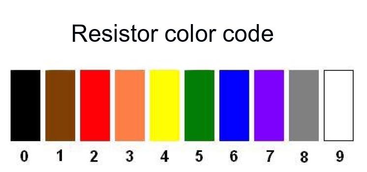
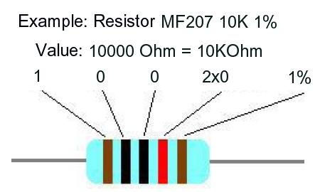
2 0 UK-electronic Color table for resistors MF07 FTE % and a example
3 Bill of material Quantity Description Mono jack ¼ Stereo jack ¼ Steel washer 0,mm DPDT Switch Fresnel Lens for mm with spacer blue, green, red Pot K-B angled (linear) Pot 00K-A angled (log.) Pot 00K-B angled (linear) Pot M-A angled (log.) Steel washer 7.mm DC-kacj isolated./.mm Z-Diode ZPD Schottky Diode N87 LED blue, green, red mm LED red mm Low Current ICL70SCPA (DC-DC converter) LF (Dual OPV, JFET-inputs) IC Socket 8-pole pcs. to isolating pots from pcb Resistor 7R (yellow/violet/black/gold/brown) Resistor 00R (brown/black/black/black/brown) Resistor K (brown/black/black/brown/brown) Resistor K (red/black/black/brown/brown) Resistor k (red/red/black/brown/brown) Resistor K7 (yellow/violet/black/brown/brown) Resistor K (red/red/black/red/brown) Resistor 7K (yellow/violet/black/red/brown) Resistor 00K (brown/black/black/orange/brown) RLD LED blue Resistor M (brown/black/black/yellow/brown) Resistor M (red/red/black/yelow/brown) Capacitor ceramik pf Capacitor foil FKP 0pF Capacitor foil MKT nf (0.0µF) Capacitor foil MKT 8nF (0.08µF) Capacitor foil MKT 0nF (0.µF) Capacitor foil MKT 70nF (0.7µF) Electrolytic capacitor RASM.µF/0V Electrolytic capacitor Elko RASM 0µF/V Electrolytic capacitor RA 00/V Battey connector some coloured wire PCB PLEXICLONE Cable fastener 0 UK-electronic


4 Top an Bottom PCB Soldering pcb First, the circuit board is populated on the basis of the placement plan or imprint on the board. For this purpose, you should start with the lowest components to assemble, i.e. first the resistors, diodes, the IC socket, pinheader and finally the capacitors. The connections to the potentiometer only after inserting the board into the chassis manufactured. For this purpose simply short pieces of wire (eg the cut ends of the resistors used). Clean work, in particular the execution of the solder joints and the exact placement of the components should have top priority, as it is this is a through-hole printed circuit board and, in contrast to a single-layer printed circuit board is not as easy to correct any incorrect configurations are (Especially when multipolar elements), The next step is to edit the enclosure, if there is no pre-drilled is used. The wiring of the input connector with the two blue ground wires, the battery clip and the tip of the input jack (white wire) should be made in advance, as well as the connection to the DC power jack and the two wires Ub and ground for supply boards. All you see in the image below what is shown. 0 UK-electronic


5 Thereafter, the circuit board is adhered by means of the supplied.mm spacer to fit on the two outer potentiometer. In what is shown below the photo LED bezel with the corresponding LEDs and the DPDT switches are already fitted. You should definitely pay attention to the correct assignment of the LEDs, as each LED has its own resistor. If, for example, taken the red LED instead of the blue LED will be unlit as the Rv of the blue LED is 00KOhm. The cathodes of LEDs (short leg) always points to the switch. The power supply of the board is then simply soldered from above. 0 UK-electronic

6 Sits the board in the enclosure, the potentiometers are soldered with short pieces of wire, as already described above. After that then the input socket to be mounted and the remaining wires are according to the wire map drawn at the corresponding points. The cathodes of the LEDs can be easily soldered to the corresponding Lugs switch. The whole is then analogous to with the wiring diagram shown below. 0 UK-electronic
7 The appendix contains the wire map, a second wiring variant for true bypass and separate Boost control (requires PDT switch - not included) as well as templates for a template and for the pressure of a possible film. When printing the PDF print files, set the printer to "No adjustment" The lead wires are easily soldered from above into the holes, with some you can even solder from below the wires. Changes: Who intends to operate the device with DC 8V, must make a few changes. The most important use of a TC9 in place of ICL70SCPA be provided. Thus, the protective diode (Zener diode V) can be dispensed with for the 70 or the security a zener diode of 8V is soldered, since the TC9 can be operated up to 8V. The pin has the TC9 no boost function and, accordingly, the two jumpers JP and JP must be set according to the description. (see above in the assembly diagram) As enclosure you can use the size 90BB, GEH090, 980. Drill diameter: DPDT Switch, DC-jack: mm Potentiometer : 7mm LED bezel: mm With clean design and proper wiring, the effects device should work immediately. For any questions we are always at your disposal. 0 UK-electronic
8
9
10 RLD RLS RLB Beschaltung für höhere Spannung bei Verwendung eines TC9CPA - 7R IC IC M K 0n 0p M K K K 7K n K 8n K 0p K7 70n K 70n K p 00R K 9V 8.7V -8.7V UB max8v -Ub max 8V CRUNCH LV CAP- BOOST VOUT V 8 OSC 7 CAP IC ICA 7 ICB 8 ICA 7 ICB 8 S R T J SLEEVE TIP D D - G X C C LED LED LED LED HI-GAIN SELECT SELECT C7 TONE LEVEL LED DRIVE DRIVE BOOST LED BOOST_SW BOOST_SW LED7 LV CAP- BOOST VOUT V 8 OSC 7 CAP IC C C D JP JP 00K-A ICL70SCPA LFN LFN LFN LFN N87 ZPD F 0/ 0/ M-A µ K-B 00K-B V V V- V- V- V V 00K-B V V TC9 0/ 0/ ZPD8
11
12
UK-electronic 2008/13
 UK-electronic 2008/13 Assembly manual for Kit BOR Clone Rev. 1.22 (2N7000) Ver. 2014 Page 3...Bill of material Page 4..5...soldering the pcb Page 5...pcb layout top Page 6...wiring diagram Page 7..8...enclosure,
UK-electronic 2012/15 Manual for the Tap Tremolo Rev. 2.0 Based on TAPLFO from Tom Wiltshire (www.electricdruid.com)
") UK-electronic 2012/15 Manual for the Tap Tremolo Rev. 2.0 Based on TAPLFO from Tom Wiltshire (www.electricdruid.com) Page 1..2...Basics Page 3...short Circuit description Page 4...Bill of material Page
UK-electronic 2012/15 Manual for the Tap Tremolo Rev. 2.0 Based on TAPLFO from Tom Wiltshire (www.electricdruid.com) Page 1..2...Basics Page 3...short Circuit description Page 4...Bill of material Page
UK-electronic Manual D verb 3 with the Belton BTDR-3 Modul
 UK-electronic 2014 Manual D verb 3 with the Belton BTDR-3 Modul Page 1 2...Introduction, hort circuit description Page 3 4...Basics Page 5 6...Bill of material Page 5...7...oldering the pcb Page 8...9...Mechanical
Build Your Own Clone Chancellor Kit Instructions
 Build Your Own Clone Chancellor Kit Instructions Warranty: BYOC, Inc. guarantees that your kit will be complete and that all parts and components will arrive as described, functioning and free of defect.
Build Your Own Clone Spring Reverb Kit Instructions
 Build Your Own Clone Spring Reverb Kit Instructions Warranty: BYOC, Inc. guarantees that your kit will be complete and that all parts and components will arrive as described, functioning and free of defect.
Build Your Own Clone Green Pony Kit Instructions
 Build Your Own Clone Green Pony Kit Instructions Warranty: BYOC, Inc. guarantees that your kit will be complete and that all parts and components will arrive as described, functioning and free of defect.
ABC V1.0 ASSEMBLY IMPORTANT!
 ABC V1.0 ASSEMBLY Before starting this kit, prepare the following tools: Soldering iron (15-20W will do), flush cutters, no.2 hex screwdriver or allen key and phillips screwdriver. Also briefly go through
STEP 0 Prepare the Materials.
 How to Build a Germanium Fuzz Guitar Effect. This document will guide you to build and test your Germanium Fuzz guitar pedal. With all the materials on hand, it takes around 2-4 hours to build it. Try
Rangemaster Treble Booster Kit Building Manual
 Rangemaster Treble Booster Kit Building Manual Effect Pedal Kits: Rangemaster Treble Booster The Dallas Rangemaster is the most famous treble booster effect pedal, and it was the first pedal of its kind.
Build Your Own Clone Mouse Kit Instructions
 Build Your Own Clone Mouse Kit Instructions Warranty: BYOC, Inc. guarantees that your kit will be complete and that all parts and components will arrive as described, functioning and free of defect. Soldering,
LITTLE NERD v1.1 Assembly Guide
 last update: 9. 3. 2016 LITTLE NERD v1.1 Assembly Guide bastl instruments.com INTRODUCTION This guide is for building Little Nerd module from Bastl Instruments. It is good to have basic soldering skills
Build Your Own Clone Crown Jewel Kit Instructions
 Build Your Own Clone Crown Jewel Kit Instructions Warranty: BYOC, Inc. guarantees that your kit will be complete and that all parts and components will arrive as described, functioning and free of defect.
Build Your Own Clone Li l Echo Kit Instructions
 Build Your Own Clone Li l Echo Kit Instructions Warranty: BYOC, Inc. guarantees that your kit will be complete and that all parts and components will arrive as described, functioning and free of defect.
Build Your Own Clone Silver Pony Kit Instructions
 Build Your Own Clone Silver Pony Kit Instructions Warranty: BYOC, Inc. guarantees that your kit will be complete and that all parts and components will arrive as described, functioning and free of defect.
Build Your Own Clone Reverb Kit Instructions
 Build Your Own Clone Reverb Kit Instructions Warranty: BYOC, LLC guarantees that your kit will be complete and that all parts and components will arrive as described, functioning and free of defect. Soldering,
Ultimatum Fuzz. The Ultimate experience in vintage-style octave-up fuzz
 Ultimatum Fuzz The Ultimate experience in vintage-style octave-up fuzz Contents of this document are 2015 Pedal Parts Ltd. No reproduction permitted without the express written permission of Pedal Parts
BYOC Vibrato Kit Instructions BA6110 version
 BYOC Vibrato Kit Instructions BA6110 version Please read these instructions very thoroughly before building even if you are an experience builder. Because of the
BYOC Vibrato Kit Instructions BA662A version
 BYOC Vibrato Kit Instructions BA662A version Please read these instructions very thoroughly before building even if you are an experience builder. Because of the layout, there is a certain order which
Build Your Own Clone Classic Overdrive Kit Instructions
 Build Your Own Clone Classic Overdrive Kit Instructions Warranty: BYOC, LLC guarantees that your kit will be complete and that all parts and components will arrive as described, functioning and free of
Build Your Own Clone Divided Octave Kit Instructions
 Build Your Own Clone Divided Octave Kit Instructions Warranty: BYOC, Inc. guarantees that your kit will be complete and that all parts and components will arrive as described, functioning and free of defect.
TS500 Assembly guide. Soldering. TS500 Assembly guide Main PCB 1. Diodes. Document revision 1.2 Last modification : 17/12/16
 TS500 Assembly guide Safety warning The kits are main powered and use potentially lethal voltages. Under no circumstance should someone undertake the realisation of a kit unless he has full knowledge about
Build Your Own Clone Analog Chorus Kit Instructions
 Build Your Own Clone Analog Chorus Kit Instructions Warranty: BYOC, Inc. guarantees that your kit will be complete and that all parts and components will arrive as described, functioning and free of defect.
KASTLE v1.5 - Assembly Guide
 last update: 14. 12. 2017 KASTLE v1.5 - Assembly Guide bastl-instruments.com INTRODUCTION Welcome to the assembly guide for the Kastle kit - mini modular synthesizer. It is suitable for beginners. It is
Build Your Own Clone Li l Reverb Kit Instructions
 Build Your Own Clone Li l Reverb Kit Instructions Warranty: BYOC, Inc. guarantees that your kit will be complete and that all parts and components will arrive as described, functioning and free of defect.
Guitarpedalkits.com Overdrive Pedal Build Instructions
 Page 1 Guitarpedalkits.com Overdrive Pedal Build Instructions Follow the instructions in this guide to build your very own DIY overdrive pedal from GuitarPedalKits.com. If you re a first time builder,
Build Your Own Clone 27V Boost Kit Instructions
 Build Your Own Clone 27V Boost Kit Instructions Warranty: BYOC, Inc. guarantees that your kit will be complete and that all parts and components will arrive as described, functioning and free of defect.
VOLUME AND TONE CONTROL - PREAMPLIFIER K8084
 VOLUME AND TONE CONTROL - PREAMPLIFIER K8084 When using one of our amplifiers (big or small), you always need a volume control and preferably also a tone control H8084IP-1 Features & specifications When
Build Your Own Clone British Blues Overdrive Kit Instructions
 Build Your Own Clone British Blues Overdrive Kit Instructions Warranty: BYOC, LLC guarantees that your kit will be complete and that all parts and components will arrive as described, functioning and free
Build Your Own Clone Kuzco Jr. Kit Instructions
 Build Your Own Clone Kuzco Jr. Kit Instructions Warranty: BYOC, Inc. guarantees that your kit will be complete and that all parts and components will arrive as described, functioning and free of defect.
Super Nova Distortion
 Super Nova Distortion The Super Nova is a reworking of the Marshall Guv'nor circuit. It uses the same gain structure as its parent design but is EQ'ed quite differently. The basic tone from the gain stages
NEW WAVE CV GENERATOR Build Document last updated september 2017 for PCB version 1.0
 NEW WAVE CV GENERATOR Build Document last updated september 2017 for PCB version 1.0 The New Wave is a Control Voltage Generator. It has two LFO's (low frequency oscillators) and four different output
GuitarPCB.com Presents. Fuzzy Bee v2 (Pump d Up Edition) Build Instructions
 Build Instructions") GuitarPCB.com Presents Fuzzy Bee v2 (Pump d Up Edition) Build Instructions Board Dimensions (W x H) 2.13 x 1.67 i.e.: 54.0mm x 42.4mm. This design will fit into a 1290NS/1590B size enclosure or larger.
GuitarPCB.com Presents Fuzzy Bee v2 (Pump d Up Edition) Build Instructions Board Dimensions (W x H) 2.13 x 1.67 i.e.: 54.0mm x 42.4mm. This design will fit into a 1290NS/1590B size enclosure or larger.
Build Your Own Clone The Swede Kit Instructions
 Build Your Own Clone The Swede Kit Instructions Warranty: BYOC, Inc. guarantees that your kit will be complete and that all parts and components will arrive as described, functioning and free of defect.
Build Your Own Clone Classic Phaser Kit Instructions
 Build Your Own Clone Classic Phaser Kit Instructions Warranty: BYOC, Inc. guarantees that your kit will be complete and that all parts and components will arrive as described, functioning and free of defect.
Build Your Own Clone Silver Pony 2 Kit Instructions
 Build Your Own Clone Silver Pony 2 Kit Instructions Warranty: BYOC, Inc. guarantees that your kit will be complete and that all parts and components will arrive as described, functioning and free of defect.
Multiwave. Guitar Synthesizer. Build Document last updated november 2018 Version
 Multiwave Guitar Synthesizer Build Document last updated november 2018 Version 1.0 2018 The Multiwave is a guitar controlled oscillator with 3 different waveshapes: saw, triangle and square. Combined,
GuitarPCB.com Angry Red Camel Build Instructions
 GuitarPCB.com Angry Red Camel Build Instructions Board Dimensions (W x H) 1.95 x 1.65 inches, i.e.: 49.5 x 41.9mm. This design will fit into a 1290NS/1590B size enclosure or larger. This is a variant of
THE RING RESONATOR (K-975)
") THE RING RESONATOR (K-975) OUTPUT BOOST The Ring Resonator An Octave Up Fuzz Modkitsdiy.com 9 VDC CENTER (-) ADAPTER TO AMP IN FROM GUITAR OUT Unplug when not in use to save battery life. Use these instructions
THE RING RESONATOR (K-975) OUTPUT BOOST The Ring Resonator An Octave Up Fuzz Modkitsdiy.com 9 VDC CENTER (-) ADAPTER TO AMP IN FROM GUITAR OUT Unplug when not in use to save battery life. Use these instructions
Build Your Own Clone Li l Beaver (Ram s Head) Kit Instructions
 Kit Instructions") Build Your Own Clone Li l Beaver (Ram s Head) Kit Instructions Warranty: BYOC, Inc. guarantees that your kit will be complete and that all parts and components will arrive as described, functioning and
Build Your Own Clone Li l Beaver (Ram s Head) Kit Instructions Warranty: BYOC, Inc. guarantees that your kit will be complete and that all parts and components will arrive as described, functioning and
Build Your Own Clone Tremolo Kit Instructions
 Build Your Own Clone Tremolo Kit Instructions Warranty: BYOC, LLC guarantees that your kit will be complete and that all parts and components will arrive as described, functioning and free of defect. Soldering,
etap2hw Vintage echo emulation DIY kit BUILDING INSTRUCTIONS Newtone Version UPDATE VERSION 2.0 May 2015
 WWW.-ONLINE.NL etap2hw Vintage echo emulation DIY kit BUILDING INSTRUCTIONS Newtone Version UPDATE VERSION 2.0 May 2015 P. Verbruggen, Newtone-online.nl, G.J. van Helden, M. Snijders, M. Boesewinkel Page
Axis Fuzz Kit Building Manual
 Axis Fuzz Kit Building Manual Effect Pedal Kits: Axis Fuzz The Axis Fuzz Kit is based in the Roger Mayer Axis Fuzz, the effect pedal responsible for Jimi Hendrix sound in Axis Bold As Love. What else is
Build Your Own Clone Li l Pony Kit Instructions
 Build Your Own Clone Li l Pony Kit Instructions Warranty: BYOC, Inc. guarantees that your kit will be complete and that all parts and components will arrive as described, functioning and free of defect.
FM RADIO KIT ESSENTIAL INFORMATION. Version 2.0 GET IN TUNE WITH THIS
 ESSENTIAL INFORMATION BUILD INSTRUCTIONS CHECKING YOUR PCB & FAULT-FINDING MECHANICAL DETAILS HOW THE KIT WORKS GET IN TUNE WITH THIS FM RADIO KIT Version 2.0 Build Instructions Before you start, take
Wiring Manual NEScaf April 2010 (August 2006)
") Wiring Manual NEScaf April 2010 (August 2006) Switched Capacitor Audio Filter The NEScaf is a switched capacitor audio filter (acronym SCAF) built around a building-block type filter chip. The NEScaf will
Wiring Manual NEScaf April 2010 (August 2006) Switched Capacitor Audio Filter The NEScaf is a switched capacitor audio filter (acronym SCAF) built around a building-block type filter chip. The NEScaf will
BYOC Analog Delay Kit Instructions
 BYOC Analog Delay Kit Instructions Please read through the instructions completely before beginning this project. This is one of our most difficult kits and it is a little different than other BYOC kits,
MONO AMPLIFIER KIT ESSENTIAL INFORMATION. Version 3.0 CREATE YOUR OWN SPEAKER DOCK WITH THIS
 ESSENTIAL INFORMATION BUILD INSTRUCTIONS CHECKING YOUR PCB & FAULT-FINDING MECHANICAL DETAILS HOW THE KIT WORKS CREATE YOUR OWN SPEAKER DOCK WITH THIS MONO AMPLIFIER KIT Version 3.0 Build Instructions
INTO THE UNKNOWN Build Document last updated may 2016 Version
 INTO THE UNKNOWN Build Document last updated may 2016 Version 1.0 2015 'Into the Unknown Guitar Synthesizer Deluxe' is a CMOS based fuzz centered around the CD4046 PLL (phase locked loop) chip and a CD4015
Build Your Own Clone B.G. Fuzz Kit Instructions
 Build Your Own Clone B.G. Fuzz Kit Instructions Warranty: BYOC, Inc. guarantees that your kit will be complete and that all parts and components will arrive as described, functioning and free of defect.
Electric Druid Flangelicious Flanger Project
 Electric Druid Flangelicious Flanger Project (Using either 4KNOBFLANGE or MULTIFLANGE chips) Overview! 2 Build Instructions! 2 Populate the PCB! 2 1N4148 Diodes! 2 Resistors! 2 Cup of tea and soldering
Build Your Own Clone Li l Analog Chorus Kit Instructions
 Build Your Own Clone Li l Analog Chorus Kit Instructions Warranty: BYOC, Inc. guarantees that your kit will be complete and that all parts and components will arrive as described, functioning and free
Build Your Own Clone Mega Chorus & Vibrato Kit Instructions
 Build Your Own Clone Mega Chorus & Vibrato Kit Instructions Warranty: BYOC, Inc. guarantees that your kit will be complete and that all parts and components will arrive as described, functioning and free
Build Your Own Clone Parametric Multi-Band Compressor Kit Instructions
 Build Your Own Clone Parametric Multi-Band Compressor Kit Instructions Warranty: BYOC, Inc. guarantees that your kit will be complete and that all parts and components will arrive as described, functioning
LA502 Assembly guide Main PCB Resistors - (2)
") LA502 Assembly guide Safety warning The kits are main powered and use potentially lethal voltages. Under no circumstance should someone undertake the realisation of a kit unless he has full knowledge about
LA502 Assembly guide Safety warning The kits are main powered and use potentially lethal voltages. Under no circumstance should someone undertake the realisation of a kit unless he has full knowledge about
Build Guide CascadiA. GeFet Preamp
 Build Guide CascadiA GeFet Preamp Disclaimery stuff: This project is meant to be assembled by fellow DIYers from the Madbean forum and should only be used for the forces of good. Any other uses prohibited
UK-electronic 2014 Kit Mosfet power amplifier 100/200W Prime example! No inventory of delivery WARNING
 UK-electronic 2014 Kit Mosfet power amplifier 100/200W Prime example! No inventory of delivery WARNING Attention: this kit is not a beginners project! The voltages can +/- 60V DC and more, and are absolutely
Bi-Directional DC Motor Speed Controller 5-32Vdc (3166v2)
") General Guidelines for Electronic Kits and Assembled Modules Thank you for choosing one of our products. Please take some time to carefully read the important information below concerning use of this product.
General Guidelines for Electronic Kits and Assembled Modules Thank you for choosing one of our products. Please take some time to carefully read the important information below concerning use of this product.
GCI BRUTALIST JR. BUILD GUIDE
 GCI BRUTALIST JR. BUILD GUIDE The Brutalist Jr. is the DIY little brother to the GCI Brutalist, a high powered distortion pedal loosely based on the Providence Stampede SDT-1. It runs on 9v DC power or
THE THUNDERDRIVE (K-950)
") THE THUNDERDRIVE (K-950) OUTPUT DISTORTION Unplug when not in use to save battery life. TO AMP IN The Thunderdrive Modkitsdiy.com FROM GUITAR OUT Use these instructions to learn: How to build an effects
THE THUNDERDRIVE (K-950) OUTPUT DISTORTION Unplug when not in use to save battery life. TO AMP IN The Thunderdrive Modkitsdiy.com FROM GUITAR OUT Use these instructions to learn: How to build an effects
Foxhunt Offset Attenuator. Parts List:
 When your closing in on the fox you may find the signals to be so strong that you can no longer find a peak or null with your antenna. Sometimes the signal is so strong that the RF will leak straight into
Electric Druid 4 second Digital Delay Project
 Electric Druid 4 second Digital Delay Project Overview! 2 Build Instructions! 2 Populate the PCB! 2 Resistors! 2 Cup of tea and soldering check! 3 Power protection diode! 4 Ground link wire! 4 IC sockets!
MICROGRANNY v2.1 - Assembly Guide
 last update: 9. 5. 2017 MICROGRANNY v2.1 - Assembly Guide bastl-instruments.com INTRODUCTION Welcome to the assembly guide for the MicroGranny kit. MicroGranny is a monophonic granular sampler by Bastl
THE AGGRESSOR (K-995)
") THE AGGRESSOR (K-99) TONE VOLUME DISTORTION MID-SHIFT SWITCH LED The Aggressor Distortion Pedal Modkitsdiy.com 9 VDC CENTER (-) ADAPTER TO AMP IN FROM GUITAR OUT Unplug when not in use to save battery
THE AGGRESSOR (K-99) TONE VOLUME DISTORTION MID-SHIFT SWITCH LED The Aggressor Distortion Pedal Modkitsdiy.com 9 VDC CENTER (-) ADAPTER TO AMP IN FROM GUITAR OUT Unplug when not in use to save battery
Simple LFO Features. 2. Application. 3. Description. Simple and easy to build LFO module for Analog Synthesizers.
 Simple LFO. Simple and easy to build LFO module for Analog Synthesizers.. Features Square and Triangle waveforms (90 phase shifted) Dual range frequencies Frequency ranges from under Hz up to several khz
πλ² Synthesizer Manual for Assembly Kit Features 2 Oscillators 4 Waveforms 32 Presets 32 User presets
 πλ² Synthesizer Manual for Assembly Kit Features 2 Oscillators 4 Waveforms 32 Presets 32 User presets Specifications Power supply: +5V DC/50mA Dimensions: 100 x 100 x 23mm Congratulations on purchasing
Build Your Own Clone Li l Beaver (Triangle Version) Kit Instructions
 Kit Instructions") Build Your Own Clone Li l Beaver (Triangle Version) Kit Instructions Warranty: BYOC, Inc. guarantees that your kit will be complete and that all parts and components will arrive as described, functioning
Build Your Own Clone Li l Beaver (Triangle Version) Kit Instructions Warranty: BYOC, Inc. guarantees that your kit will be complete and that all parts and components will arrive as described, functioning
SoftRock v5.0 Builder s Notes. December 12, Building a QSD Kit
 SoftRock v5.0 Builder s Notes December 12, 2005 Building a QSD Kit Be sure to use a grounded tip soldering iron in building the QSD board. The soldering iron needs to have a small tip, (0.05-0.1 inch diameter),
Build instructions for the BLÜE MONSTER Dual band FET OD diy kit!
 Blue Monster, v.1.11... 1(11) Build instructions for the BLÜE MONSTER Dual band FET OD diy kit! Thanx for getting your hands on the BLÜE MONSTER diy kit! In a near future you will have some fun building
Build Your Own Clone Analog Vibrato Kit Instructions
 Build Your Own Clone Analog Vibrato Kit Instructions Warranty: BYOC, Inc. guarantees that your kit will be complete and that all parts and components will arrive as described, functioning and free of defect.
Raygun. Vector Weapon. projects. Raygun vector weapon. Build a mini analog sound-effects circuit. By Symetricolour. Time: 2 4 hours CosT: $15 $20
 projects Raygun vector weapon Raygun Vector Weapon By Symetricolour Time: 2 4 hours CosT: $5 $20 Build a mini analog sound-effects circuit. Gregory Hayes 02 Materials» raygun Vector Weapon Kit item #MSVWP
DIODE / TRANSISTOR TESTER KIT
 DIODE / TRANSISTOR TESTER KIT MODEL DT-100K 99 Washington Street Melrose, MA 02176 Phone 781-665-1400 Toll Free 1-800-517-8431 Visit us at www.testequipmentdepot.com Assembly and Instruction Manual Elenco
Marchand Electronics Inc.
 Marchand Electronics Inc. Rochester, NY. TEL:(585) 423 0462 www.marchandelec.com Electronic Crossover XM1 XM1 ELECTRONIC CROSSOVER NETWORK In many high performance loudspeaker systems the individual loudspeaker
THE GREEN CURRANT TREMOLO Build Document last updated june 2017 for PCB version 1.5
 THE GREEN CURRANT TREMOLO Build Document last updated june 2017 for PCB version 1.5 The Green Currant tremolo is a very percussive and vibey tremolo based around the TDA7052A amplifier chip. It splits
DELUXE STEREO AMPLIFIER KIT
 TEACHING RESOURCES SCHEMES OF WORK DEVELOPING A SPECIFICATION COMPONENT FACTSHEETS HOW TO SOLDER GUIDE CREATE YOUR OWN SPEAKER DOCK WITH THIS DELUXE STEREO AMPLIFIER KIT Version 2.0 Index of Sheets TEACHING
MP573 Assembly guide. Soldering. MP573 Assembly guide PCB split PCB split. Document revision 2.2 Last modification : 22/08/17
 MP573 Assembly guide Safety warning The kits are main powered and use potentially lethal voltages. Under no circumstance should someone undertake the realisation of a kit unless he has full knowledge about
Liquid Mercury Phaser. Build doc V2.0
 Liquid Mercury Phaser Build doc V2.0 David Rolo / December 2014 The build consists of 2 boards that were designed to fit in a BB enclosure with top mounted open jacks. PCB1 holds the pcb mounted pots and
DIODE / TRANSISTOR TESTER KIT
 DIODE / TRANSISTOR TESTER KIT MODEL DT-100K Assembly and Instruction Manual Elenco Electronics, Inc. Copyright 1988 Elenco Electronics, Inc. Revised 2002 REV-K 753110 DT-100 PARTS LIST If you are a student,
Penrose Quantizer Assembly Guide
 Penrose Quantizer Assembly Guide Schematic and BOM The schematic can be found here: www.sonic-potions.com/public/penrosequantizerschematic.pdf The BOM is available at google docs: Link to BOM Prepare the
Value Location Qty Potentiometers C1M Distortion 1 A10k Volume 1. Footswitch 3PDT SW1 1. Jacks 1/4 Mono 2 DC Power 1
 Distortion BUILD INSTRUCTIONS Thank you for your purchase of our Distortion+ kit! We have completely redesigned our entire line of kits to be the most user friendly, while still maintaining their same
Bill of Materials: PWM Stepper Motor Driver PART NO
 PWM Stepper Motor Driver PART NO. 2183816 Control a stepper motor using this circuit and a servo PWM signal from an R/C controller, arduino, or microcontroller. Onboard circuitry limits winding current,
VFE Switching Board madbeanpedals Some images 2017 VFE Pedals, used with permission 8.7 update: see pg W x 1.33 H
 VFE Switching Board 2017 madbeanpedals Some images 2017 VFE Pedals, used with permission 8.7 update: see pg. 7 2.16 W x 1.33 H The VFE Switching Board and micro-controller are included with all the VFE
400W MONO/STEREO AMPLIFIER
 400W MONO/STEREO AMPLIFIER Universal, robust and compact are the words to describe this amplifier. Total solder points: 264 Difficulty level: beginner 1 2 3 4 5 advanced K4005B ILLUSTRATED ASSEMBLY MANUAL
Build Your Own Clone Li l Comp Kit Instructions
 Build Your Own Clone Li l Comp Kit Instructions Warranty: BYOC, Inc. guarantees that your kit will be complete and that all parts and components will arrive as described, functioning and free of defect.
Component Identification
 Generic Skills for Microelectronic Engineers Component Identification AIM: To be able to identify common electronic components used in miniature and medium power applications. Methods of labelling, range
Switcher Assembly guide. Switcher Assembly guide 1. Soldering. 2. Switcher3 vs Switcher2. 3. PCB split.
 Safety warning The kits are main powered and use potentially lethal voltages. Under no circumstance should someone undertake the realisation of a kit unless he has full knowledge about safely handling
REFRACTOR PROJECT NAME. BASED ON Klon Centaur / KTR. BUILD DIFFICULTY Intermediate. DOCUMENT VERSION Overdrive ( ) EFFECT TYPE
 EFFECT TYPE") PROJECT NAME REFRACTOR BASED ON Klon Centaur / KTR BUILD DIFFICULTY Intermediate EFFECT TYPE DOCUMENT VERSION Overdrive 1.0.0 (2018-08-12) PROJECT SUMMARY A part-for-part replica of a mythical overdrive
PROJECT NAME REFRACTOR BASED ON Klon Centaur / KTR BUILD DIFFICULTY Intermediate EFFECT TYPE DOCUMENT VERSION Overdrive 1.0.0 (2018-08-12) PROJECT SUMMARY A part-for-part replica of a mythical overdrive
Chunky Cheese Build Guide Rev
 Chunky Cheese Build Guide Rev. 2008-08-04 The Chunky Cheese is a slightly-modified version of the discontinued Big Cheese fuzz pedal. Table of Contents Table of Contents... 1 PCB Layout... 2 Parts List...
The Tellun Corporation. TLN-861 Dunsel. User Guide, Rev Scott Juskiw The Tellun Corporation
 The Tellun Corporation TLN-861 Dunsel User Guide, Rev. 1.0 Scott Juskiw The Tellun Corporation scott@tellun.com TLN-861 User Guide Revision 1.0 August 31, 2006 1. Introduction The TLN-861 Dunsel is a collection
Glue Fuzz Mounting instructions.
 Glue Fuzz Mounting instructions. Index Important notice. 2 What's in the kit? 3 What you'll need. 4 Soldering on the pcb. 4 Wiring the pedal. 11 Test the board. 12 Debugging chapter. 13 Copyright Zorg
Beta-test ED1 PCB installed in I0CG s K1
 K1 SSB Modification (Ed.2) This description provides the receiver (RX) modifications, assembly, alignment and operation as a first step. In a second step you can add the remaining transmitter (TX) modifications,
Manual Version July 2007
 Manual Version 1.2 - July 2007 Page 1 Table of Contents Section1: M3 Phono Board Build...3 Phono Board Parts List...3 Preparation...4 Fitting the Valve Bases...6 Installing the Resistors...7 Starting the
Assembly and User Guide
 Assembly and User Guide AtariPunkr is an adjustable stepped tone generator. AtariPunkr provides hours of fun everyone! Powered by: 9V Battery Outputs: Mylar Speaker (Included) Stereo Output (3.5mm Jack)
Workshop Part Identification Lecture N I A G A R A C O L L E G E T E C H N O L O G Y D E P T.
 Workshop Part Identification Lecture N I A G A R A C O L L E G E T E C H N O L O G Y D E P T. Identifying Resistors Resistors can be either fixed or variable. The variable kind are called potentiometers
The Tellun Corporation. TLN-863 Max Min Generator. User Guide, Rev Scott Juskiw The Tellun Corporation
 The Tellun Corporation TLN-863 Max Min Generator User Guide, Rev. 1.1 Scott Juskiw The Tellun Corporation scott@tellun.com TLN-863 User Guide Revision 1.1 May 26, 2008 1. Introduction The TLN-863 Max Min
1. PCB and schematic
 1. PCB and schematic 2. Assembly manual WHAT'S IN THE BOX 1 x PCB tape: o 5 x jumper o 6 x resistor 1K o 12 x resistor 10K o 1 x resistor 15K o 8 x resistor 100K o 2 x resistor 47K 4 x 14p IC socket 4
Instruction Manual. CT101 line stage / linear preamplifier module
 CT0 line stage / linear preamplifier module CT0 CONTENT UNPACKG channel line stage / linear preamplifier module Unpacking Connections Definitions Power supply Signal input Signal output Volume control
D-VERB Digital Reverb Unit
 This is the D-VERB (Digital Reverb) kit. It is an excellent sounding reverb pedal, simple to build and compact for the pedal board. The source of the reverb sound is a digital reverb module made called
Dual Digital Build Manual
 Dual Digital Build Manual Introduction This document is meant to aid you in assembling your Dual Digital Oscillator (DDO from now on). Some instructions may be a bit basic for advanced builders but I hope
How To Tame A Wild Mouse
 How To Tame A Wild Mouse By Steve Daniels, President, Small Bear Electronics LLC What's A Wild Mouse? This Wild Mouse is an active tone boost--an amplifier that is tuned with a filter so that it boosts
DRTXM2 TRANSMITTER BILL OF MATERIAL IDENT QTY PART NUMBER DESCRIPTION
 DRTXM2 TRANSMITTER BILL OF MATERIAL H1 C1-5,7,10-11,15,17-18,20, 22-28,34,38, 43-46,49-53,1A,2A 8 Right Angle LED Mount 0 0.01uf 50V Ceramic Disc Capacitor 31 0.1 UF/50V Decoupling Capacitors C13,14,39-42