1. PCB and schematic
|
|
|
- Zoe Russell
- 5 years ago
- Views:
Transcription
1 1. PCB and schematic
2
3 2. Assembly manual
4 WHAT'S IN THE BOX 1 x PCB tape: o 5 x jumper o 6 x resistor 1K o 12 x resistor 10K o 1 x resistor 15K o 8 x resistor 100K o 2 x resistor 47K 4 x 14p IC socket 4 x ceramic capacitor 100pF 5 x ceramic capacitor 1nF 2 x ceramic capacitor 22nF 5 x ceramic multilayer capacitor 1µF 1 x slide switch 1 x red LED 1 x stereo phone jack 3,5mm 2 x potmeter 50K 4 x capacitor 100µF/25V 2 x electret microcel 4 x IC 2 x plastic knob 1 x battery holder 2 x plastic spacer 2 x M3 nut 2 x M3 bolt

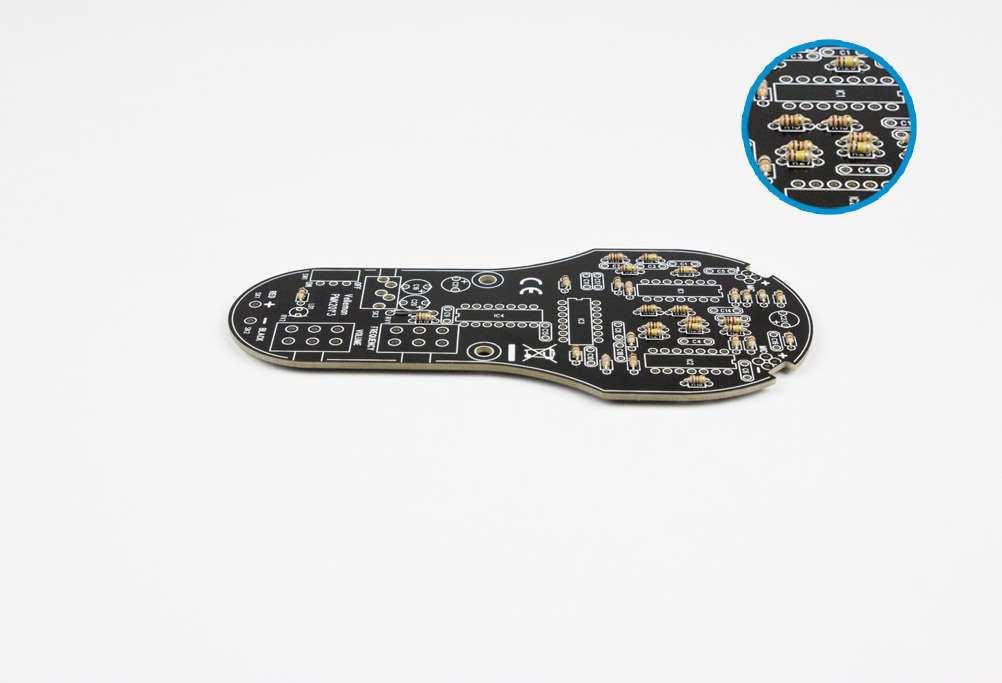
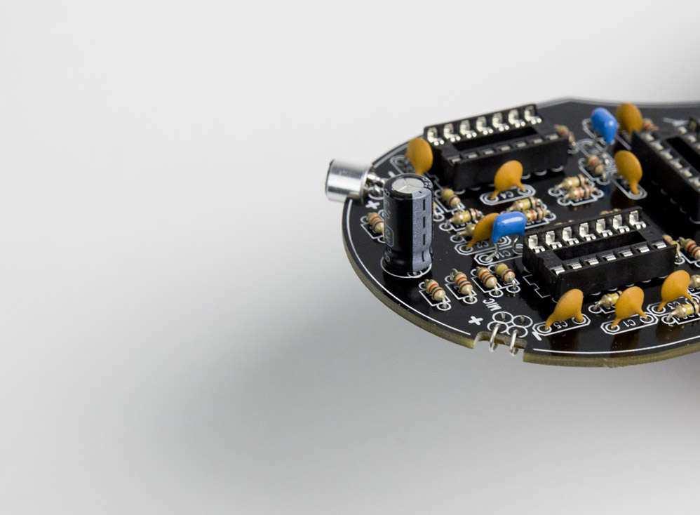
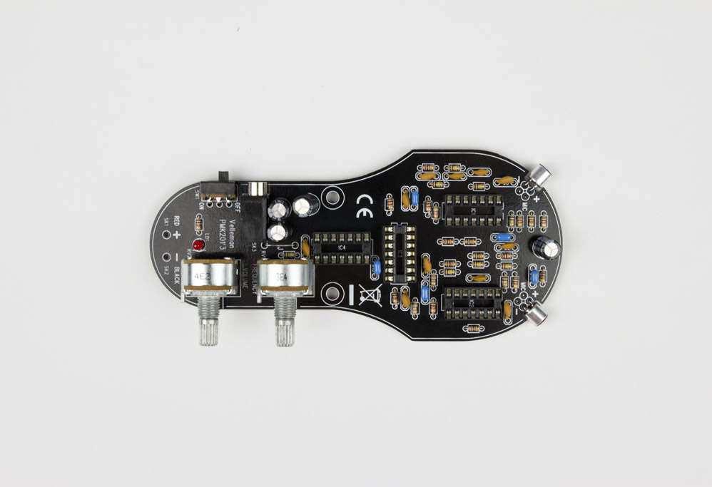
5 ASSEMBLY MANUAL Let's start by analysing the PCB; Component side:
6 Solder side:

7 Now follow the steps below in order to solder your kit properly. Good luck! 1. Jumper J
 R7.")
 R28.")
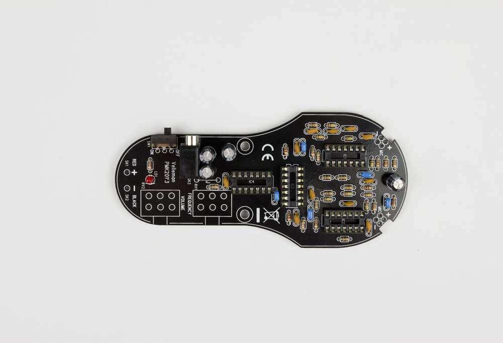
8 2. Resistors Note: all resistors are placed in the correct order of usage on the supplied tape. R1... R6: 1K (brown, black, red) R7... R18: 10K (brown, black, orange) R19: 15K (brown, green, orange) R20... R27: 100K (brown, black, yellow) R28... R29: 47K (yellow, violet, orange)
9
 C5... C9: 1nF (102) C10.")
10 3. IC socket IC1... IC4: 14p IC socket Note the position of the notch! 4. Ceramic capacitors C1... C4: 100pF (101) C5... C9: 1nF (102) C10... C11: 22nF (223)
11 5. Ceramic multilayer capacitor C14... C18: 1µF (105)

12 6. Slide switch SW1

13 7. LED LD1: red led Note the polarity!

14 8. Stereo phone jack SK3
15 9. Capacitor C19... C22: 100µF/25V Note the polarity!
16

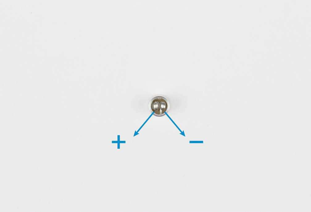
17 10. Potmeter RV1, RV2: 50K 11. Electret microcell 2 x MIC a. wind a jumper through both holes on the same side with the same polarity as shown in the picture. Then solder them together on the solder side of the PCB.
18

19

20 b. solder the microcell onto the loops of the jumpers but note the polarity!
21

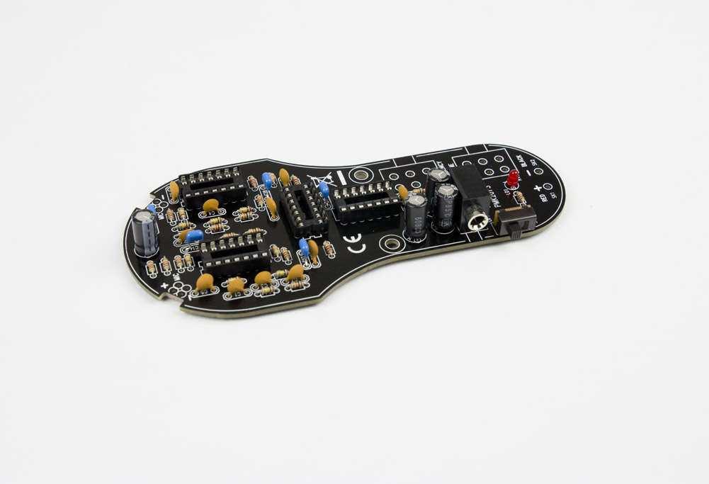
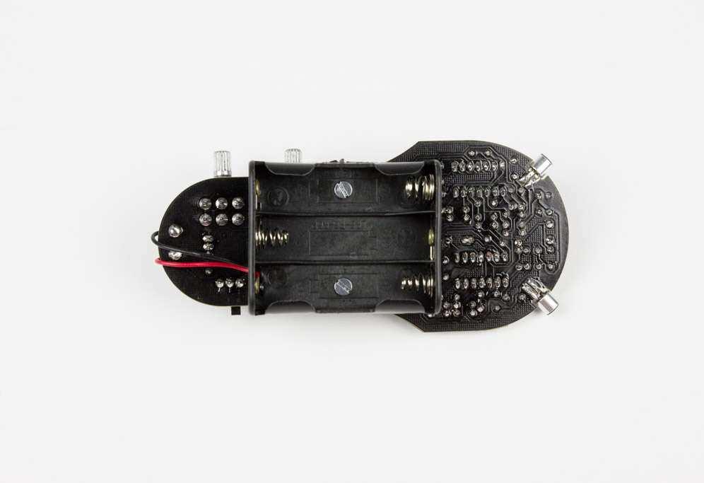
22 12. ICs IC1... IC2: TLV274 IC3: 74HC4066 IC4: 74HC14 Note the position of the notch! 13. Battery holder a. Connect the red wire of the battery holder to RED SK1 and the black wire to BLACK SK2 as shown in the picture.

23 b. Use the 2 x plastic spacers and the 2 x M3 nut and 2 x M3 bolt to install the battery holder onto the PCB as shown in the picture.
24

25 14. Knob Place both knobs onto the potentiometers. Congrats, your kit is finished!

26 3. User manual INTRODUCTION The ultrasonic detector (K8118) is an easy-to-use instrument that converts ultrasound into audible sound for humans. Therefor it can be used for studying bats and other animals that emit ultrasound. The detector uses the heterodyne conversion principle; this means that realistic sounding voices are heard, but their frequency has been shifted and are representative artifacts of the original sounds. Nevertheless, the sounds heard with this detector are highly informative. It is perfectly possible to identify bat species by careful observation in combination with this detector as their call patterns are species-specific and can be quite distinctive. The detector can be used in many other situations where detection of ultrasound is involved, such as: bearing test (early warning of bearing failure, detecting lack of lubrication) leak detection in pressurized systems (e.g. localize exhaust system leaks) electrical inspection (localize arcing, corona discharge)

27 SOME TECHNICAL INFO As mentioned above, the detector works according to the heterodyne principle. This technique means that a limited frequency range is selected for conversion into the audible range. If the frequency control is set to the middle position, the oscillator frequency is approximately 35 khz. In this case the range about 30 to 40 khz will be transformed. The incoming ultrasonic signal is mixed with a locally generated signal. The mixer output contains a signal which is the difference between these two frequencies. So for example, if the incoming sound is circa 33 khz and the local oscillator is running at 35 khz, the output will be about 2 khz. Interestingly, the same output would also be produced if the local oscillator is set to 31 khz as the mixer produces different signals in both positive- and negative senses.
28 The amplified input signal is combined with the local oscillator output in the mixer. The local oscillator is adjusted so that its tone is close to the ultrasonic frequencies of interest. The mixer effectively multiplies the ultrasonic signal with the local oscillator tone and produces audio-band signals representing their difference. The audio band amplifier buffers the mixer output and drives the headphones. INITIAL TESTING Insert the 3 x 1,5V AA batteries, connect the headphones and turn switch SW1 to the ON position. To test the detector, perform the following steps: 1. Set the VOLUME control to about middle position so that some noise is heard in the headphones. 2. Then turn the FREQUENCY control to the middle position to get the oscillator frequency to about 35 khz. 3. Now gently rub two fingers together near the microphones or slide a fingertip over a sheet of paper held near to the microphones. A scraping sound should then be heard in the headphones. Another good ultrasound source is a jingling bunch of keys. USING THE BAT DETECTOR Once the detector has been tested positively, it s time to venture out at dusk. Hearing your first bat is a very nice experience. Start by setting the frequency control a little above the middle position to get about 45 khz oscillator frequency. When bats are seen flying close by, point the microphones directly at them. When a bat-like call is heard from the headphones, adjust the frequency up and down until the clearest sound is heard. The device is sensitive enough to produce good results from about 10 meters away. You are listening for a series of click or plop sounds as the bat passes by. Some species actually synchronize the clicks with wing motion, giving the illusion that its wing beats are heard, when it is actually their echolocation pulses.
BUILD A. By Jonathan Berber
 BUILD A By Jonathan Berber BAT DETECTOR Back in the 18 th century, it was suspected that bats navigated using sound, but it took until 1938 to conclusively demonstrate echolocation.the mechanism almost
ULTRASOUND DETECTOR D240x OPERATING INSTRUCTIONS. Pettersson. Phone: Fax:
 ULTRASOUND DETECTOR D240x OPERATING INSTRUCTIONS Pettersson www.batsound.com Phone:+46 1830 3880 Fax:+46 1830 3840 e-mail: info@batsound.com INTRODUCTION The ultrasound detector D240x is an easy-to-handle
Total solder points: 79 Difficulty level: beginner advanced GUITAR PREAMPLIFIER WITH HEADPHONE OUTPUT K4102 ILLUSTRATED ASSEMBLY MANUAL
 Total solder points: 79 Difficulty level: beginner 1 2 3 4 5 advanced GUITAR PREAMPLIFIER WITH HEADPHONE OUTPUT K4102 Practice the guitar without disturbing others. ILLUSTRATED ASSEMBLY MANUAL H4102IP-1
BAT DETECTOR A project of the Service Kring JOTA-JOTI.
 Manual Bat Detector kit Page 1 of 12 A project of the. Do you like the Bat Detector, do you have great ideas? Tell us, please see how on the last page. Manual Bat Detector kit... 1 Remarks... 2 Introduction...
Code Practice Oscillator (CPO) For kit building instructions turn to Page 3.
 For kit building instructions turn to Page 3.") Code Practice Oscillator (CPO) For kit building instructions turn to Page 3. Overview Many thanks for your purchase of this code practice oscillator or CPO, this guide is intended to allow you to quickly
Code Practice Oscillator (CPO) For kit building instructions turn to Page 3. Overview Many thanks for your purchase of this code practice oscillator or CPO, this guide is intended to allow you to quickly
SPACE WAR GUN KIT MODEL K-10. Assembly and Instruction Manual. Elenco Electronics, Inc.
 SPACE WAR GUN KIT MODEL K-10 Assembly and Instruction Manual Elenco Electronics, Inc. Copyright 1989 Elenco Electronics, Inc. Revised 2001 REV-H 753210A PARTS LIST Contact Elenco Electronics (address/phone/e-mail
BAT BEACON A project of the Service Kring JOTA-JOTI. Manual Bat Beacon kit.
 Manual Bat Beacon kit. Pagina 1 van 12 A project of the. Do you like the Bat-Beacon, do you have great ideas? Tell us, please see how on the last page. Manual Bat Beacon kit.... 1 Remarks... 2 Introduction...
VOLUME AND TONE CONTROL - PREAMPLIFIER K8084
 VOLUME AND TONE CONTROL - PREAMPLIFIER K8084 When using one of our amplifiers (big or small), you always need a volume control and preferably also a tone control H8084IP-1 Features & specifications When
3. Assembly manual ANALYZING THE PCB'S LCD PCB. Component side: Solder side:
 3. Assembly manual ANALYZING THE PCB'S LCD PCB Component side: Solder side: MAIN PCB Component side: Solder side: ASSEMBLGING THE LCD PCB 1. Resistor R1: 33 Ohm (orange, black, black) 2. 6 Pin female header
Wiring Manual NEScaf April 2010 (August 2006)
") Wiring Manual NEScaf April 2010 (August 2006) Switched Capacitor Audio Filter The NEScaf is a switched capacitor audio filter (acronym SCAF) built around a building-block type filter chip. The NEScaf will
Wiring Manual NEScaf April 2010 (August 2006) Switched Capacitor Audio Filter The NEScaf is a switched capacitor audio filter (acronym SCAF) built around a building-block type filter chip. The NEScaf will
Foxhunt Offset Attenuator. Parts List:
 When your closing in on the fox you may find the signals to be so strong that you can no longer find a peak or null with your antenna. Sometimes the signal is so strong that the RF will leak straight into
Building the Sawdust Regenerative Receiver
 Building the Sawdust Regenerative Receiver Introduction The Sawdust is a super regenerative receiver using the basic Armstrong design architecture. The receiver uses one toroidal transformer to provide
Ultrasonic Diagnostic Tool. Users Manual. Read this manual thoroughly before use
 Ultrasonic Diagnostic Tool Users Manual Read this manual thoroughly before use 2280 PRINCIPLE Moving parts, liquids and gases cause turbulence or friction. This turbulence or friction can then produces
Building the Sawdust Regenerative Receiver
 Building the Sawdust Regenerative Receiver Introduction The Sawdust is a super regenerative receiver using the basic Armstrong design architecture. The receiver uses one toroidal transformer to provide
LDB-1 Kit Instructions Page 1 of 8
 LDB-1 Kit Instructions Page 1 of 8 Important Information Congratulations and thank you for your purchase of the LDB-1 Little Drummer Boy Analog Drum Machine Kit! Before you start, please read the enclosed
Total solder points: 271 Difficulty level: beginner advanced. 2 x 15 LED STEREO VU METER K4306 ILLUSTRATED ASSEMBLY MANUAL
 Total solder points: 271 Difficulty level: beginner 1 2 3 4 5 advanced 2 x 15 LED STEREO VU METER K4306 For high precision audio level indication ILLUSTRATED ASSEMBLY MANUAL H4306IP-1 Features & Specifications
ASSEMBLY MANUAL FOR R3500D DIRECTION FINDING RECEIVER KIT
 SDR-Kits www.sdr-kits.net SDR-Kits is CRKITS Authorised Distributor for Europe ASSEMBLY MANUAL FOR R3500D DIRECTION FINDING RECEIVER KIT Rev. A May 24, 2015 Written by CRKITS http://www.crkits.com Thanks
The Walford Electronics Ford Receiver Kit Project Construction Manual
 The Walford Electronics Ford Receiver Kit Project Construction Manual Walford Electronics Ford Receiver construction manual V1.5 Page 1 of 22 Introduction The Ford receiver has four stages: The first stage
Mono Amplifier. LM386 Headphone Amp
 Mono Amplifier LM386 Headphone Amp Layout On/Off Switch - cuts power to the circuit Mono Input Jack: use either L or R or solder together Schematic Step 1 - Parts List 1.) R1-10ohm Resistor - Brown Black
Read This Page First
 Read This Page First If you are reading this you know the manuals are always available at QRPKITS.com. This is version 8.0 of the manual dated 4/27/2016. There is no need to print out the whole assembly
S-Pixie QRP Kit. Student Manual. Revision V 1-0
 S-Pixie QRP Kit Student Manual Revision V 1-0 Introduction The Pixie 2 is a small, versatile radio transceiver that is very popular with QRP (low power) amateur radio operators the world over. It reflects
Total solder points: 101 Difficulty level: beginner advanced ELECTRONIC WATCHDOG K2655 ILLUSTRATED ASSEMBLY MANUAL
 Total solder points: 101 Difficulty level: beginner 1 2 3 4 5 advanced ELECTRONIC WATCHDOG K2655 Listens and scares intruders with realistic barking. ILLUSTRATED ASSEMBLY MANUAL H2655IP-2 Features & Specifications
Raygun. Vector Weapon. projects. Raygun vector weapon. Build a mini analog sound-effects circuit. By Symetricolour. Time: 2 4 hours CosT: $15 $20
 projects Raygun vector weapon Raygun Vector Weapon By Symetricolour Time: 2 4 hours CosT: $5 $20 Build a mini analog sound-effects circuit. Gregory Hayes 02 Materials» raygun Vector Weapon Kit item #MSVWP
400W MONO/STEREO AMPLIFIER
 400W MONO/STEREO AMPLIFIER Universal, robust and compact are the words to describe this amplifier. Total solder points: 264 Difficulty level: beginner 1 2 3 4 5 advanced K4005B ILLUSTRATED ASSEMBLY MANUAL
TV Remote. Discover Engineering. Youth Handouts
 Discover Engineering Youth Handouts Electronic Component Guide Component Symbol Notes Amplifier chip 1 8 2 7 3 6 4 5 Capacitor LED The amplifier chip (labeled LM 386) has 8 legs, or pins. Each pin connects
MICROGRANNY v2.1 - Assembly Guide
 last update: 9. 5. 2017 MICROGRANNY v2.1 - Assembly Guide bastl-instruments.com INTRODUCTION Welcome to the assembly guide for the MicroGranny kit. MicroGranny is a monophonic granular sampler by Bastl
AM/FM RADIO KIT MODEL AM/FM-108CK SUPERHET RADIO CONTAINS TWO SEPARATE AUDIO SYSTEMS: IC AND TRANSISTOR. Assembly and Instruction Manual ELENCO
 AM/FM RADIO KIT MODEL AM/FM-108CK SUPERHET RADIO CONTAINS TWO SEPARATE AUDIO SYSTEMS: IC AND TRANSISTOR Assembly and Instruction Manual ELENCO Copyright 2012 by ELENCO All rights reserved. 753510 No part
INSPIRE VLF-3 Rev #1C Receiver Kit ASSEMBLY INSTRUCTIONS
 INSPIRE VLF-3 Rev #1C Receiver Kit ASSEMBLY INSTRUCTIONS The following assembly instructions should be followed carefully. The INSPIRE VLF-3 receiver kit is NOT a simple electronic assembly. If you follow
Building the Toothpick Audio CW Filter
 Building the Toothpick Audio CW Filter Introduction The toothpick is a simple variable bandpass audio filter designed to compliment the Splinter QRPp Trans-Receiver. The filter also contains an audio amplifier
S Pixie QRP Kit User Manual. Welcome to visit the home page to obtain the latest data. 1 / 24. Revision V160515
 S-Pixie QRP Kit User Manual Revision V160515 Welcome to visit the home page www.lxqqfy.com to obtain the latest data. 1 / 24 1. Introduction PIXIE is a very small volume of simple 40 meter band micro-power
4ms SCM Breakout. Kit Builder's Guide for PCB v2.1 4mspedals.com
 4ms SCM Breakout Kit Builder's Guide for PCB v2.1 4mspedals.com Shuffling Clock Multiplier Breakout This guide is for building a Shuffling Clock Multiplier Breakout module (SCMBO) version 2.1 from the
FM RADIO KIT ESSENTIAL INFORMATION. Version 2.0 GET IN TUNE WITH THIS
 ESSENTIAL INFORMATION BUILD INSTRUCTIONS CHECKING YOUR PCB & FAULT-FINDING MECHANICAL DETAILS HOW THE KIT WORKS GET IN TUNE WITH THIS FM RADIO KIT Version 2.0 Build Instructions Before you start, take
AM RADIO KIT MODEL AM-780K. Assembly and Instruction Manual
 AM RADIO KIT MODEL AM-780K Assembly and Instruction Manual Elenco Electronics, Inc. Copyright 2007, 1999 by Elenco Electronics, Inc. All rights reserved. Revised 2007 REV-F 753108 No part of this book
AM/FM RADIO KIT MODEL AM/FM-108K INTEGRAL CIRCUIT, 9 TRANSISTORS, 4 DIODES. Assembly and Instruction Manual
 AM/FM RADIO KIT MODEL AM/FM-108K INTEGRAL CIRCUIT, 9 TRANSISTORS, 4 DIODES Assembly and Instruction Manual TM Elenco Electronics, Inc. Copyright 2003, 1989 by Elenco TM Electronics, Inc. All rights reserved.
LA502 Assembly guide Main PCB Resistors - (2)
") LA502 Assembly guide Safety warning The kits are main powered and use potentially lethal voltages. Under no circumstance should someone undertake the realisation of a kit unless he has full knowledge about
LA502 Assembly guide Safety warning The kits are main powered and use potentially lethal voltages. Under no circumstance should someone undertake the realisation of a kit unless he has full knowledge about
Assembly Manual V1R2B-Rev1.0D
 Assembly Manual V1R2B-Rev1.0D for 4 State QRP MagicBox - Solid State Transmit/Receive System Designed by: Jim Kortge, K8IQY Copyright 2009-2012 - All rights reserved This system is the result of some brainstorming
KASTLE v1.5 - Assembly Guide
 last update: 14. 12. 2017 KASTLE v1.5 - Assembly Guide bastl-instruments.com INTRODUCTION Welcome to the assembly guide for the Kastle kit - mini modular synthesizer. It is suitable for beginners. It is
N3ZI Kits General Coverage Receiver, Assembly & Operations Manual (For Jun 2011 PCB ) Version 3.33, Jan 2012
 Version 3.33, Jan 2012") N3ZI Kits General Coverage Receiver, Assembly & Operations Manual (For Jun 2011 PCB ) Version 3.33, Jan 2012 Thank you for purchasing my general coverage receiver kit. You can use the photo above as a
N3ZI Kits General Coverage Receiver, Assembly & Operations Manual (For Jun 2011 PCB ) Version 3.33, Jan 2012 Thank you for purchasing my general coverage receiver kit. You can use the photo above as a
Penrose Quantizer Assembly Guide
 Penrose Quantizer Assembly Guide Schematic and BOM The schematic can be found here: www.sonic-potions.com/public/penrosequantizerschematic.pdf The BOM is available at google docs: Link to BOM Prepare the
40106 Hex Oscillator Workshop Instructions. bbob drake, aka fluxmonkey
 40106 Hex Oscillator Workshop Instructions bbob drake, aka fluxmonkey 40106 Hex Oscillator Workshop Instructions by Bbob Drake is licensed under a Creative Commons Attribution-ShareAlike 4.0 International
LITTLE NERD v1.1 Assembly Guide
 last update: 9. 3. 2016 LITTLE NERD v1.1 Assembly Guide bastl instruments.com INTRODUCTION This guide is for building Little Nerd module from Bastl Instruments. It is good to have basic soldering skills
TS500 Assembly guide. Soldering. TS500 Assembly guide Main PCB 1. Diodes. Document revision 1.2 Last modification : 17/12/16
 TS500 Assembly guide Safety warning The kits are main powered and use potentially lethal voltages. Under no circumstance should someone undertake the realisation of a kit unless he has full knowledge about
SSB-MITE Assembly Manual. Copyright David Cripe NM0S The 4 State QRP Group. Introduction
 SSB-MITE Assembly Manual Copyright 2017 David Cripe NM0S The 4 State QRP Group Introduction Thank you for purchasing a SSB-MITE. We hope you will enjoy building it and find it a useful addition to your
Total solder points: 77 Difficulty level: beginner advanced OPTICAL PROXIMITY SWITCH K8092 ILLUSTRATED ASSEMBLY MANUAL
 Total solder points: 77 Difficulty level: beginner 1 2 3 4 5 advanced OPTICAL PROXIMITY SWITCH K8092 Operate by waving hand or object in front of unit ILLUSTRATED ASSEMBLY MANUAL H8092IP-1 Features & Specifications
FUNCTION GENERATOR KIT
 FUNCTION GENERATOR KIT MODEL FG-500K Assembly and Instruction Manual Elenco Electronics, Inc. Copyright 2005 by Elenco Electronics, Inc. All rights reserved. Revised 2005 REV-B 753069 No part of this book
RadiØKit Μ CW HAM RADIO TRANSCEIVER KIT. Assembly and operating manual
 RadiØKit-120 20Μ CW HAM RADIO TRANSCEIVER KIT Assembly and operating manual Boreiou Ipirou 78 Kolonos Athens- Greece - 10444 Tel: 210.5150527 210.5132673 www.freebytes.com Thank you for buying RadiØKit-1,
HT-1A Dual Band CW QRP Transceiver. Kit Building Instructions
 HT-A Dual Band CW QRP Transceiver Kit Building Instructions Rev B, July 8, 08 Designed by BD4RG Exclusively distributed by CRKITS.COM and its worldwide distributors Join the group http://groups.io/g/crkits
D.I.Y L.E.D CUBE 4X4X4. Level: Intermediate
 EN D.I.Y L.E.D CUBE 4X4X4 Level: Intermediate AK-125 TABLE OF CONTENTS Parts List... 2 Soldering Guide (Part A)... 3 Soldering Guide (Part B)... 5 Soldering Guide Without Recommend Products... 8 Appendix...
Assembly Instructions
 Assembly Instructions For the SSQ-2F 3.1 MHz Rife Controller Board Kit v1.41 Manual v1.00 2012 by Ralph Hartwell Spectrotek Services GENERAL ASSEMBLY INSTRUCTIONS Arrange for a clean work surface with
the insect, while the CF tones serve to determine the relative speed with respect to the insect. The echoes returned
 BAT DETECTOR Designby L. Lemmens The detector makes sounds at frequencies of 1000 khz audible to human beings. The conversion is caried out either by a superheterodyne circuit or a frequency divider. Although
Time of Arrival Radio Direction Finder.
 Time of Arrival Radio Direction Finder. Time of arrival (TOA) RDF units are simple and very useful. Various designs have been distributed over the years, and here is another one. This Kit Developed by
Ozark Patrol Assembly Manual
 Ozark Patrol Assembly Manual Copyright 2014 David Cripe NM0S The 4 State QRP Group Thank you for purchasing a Ozark Patrol kit. We hope you will enjoy building it and and find it a fun addition to your
TECHNICAL MANUAL ULTRASONIC TEST SET MODEL 42A12D JUNE 15, 1998 REV 00 SEACOM DIVISION
 TECHNICAL MANUAL ULTRASONIC TEST SET MODEL AD JUNE, 998 REV 00 SEACOM DIVISION DUKANE CORPORATION ST. CHARLES, ILLINOIS 607 PHONE: 60/8-00 FAX: 60/8- DOCUMENT NO. 0-TM-008 998 DUKANE CORPORATION 99806-08SC
DIODE / TRANSISTOR TESTER KIT
 DIODE / TRANSISTOR TESTER KIT MODEL DT-100K 99 Washington Street Melrose, MA 02176 Phone 781-665-1400 Toll Free 1-800-517-8431 Visit us at www.testequipmentdepot.com Assembly and Instruction Manual Elenco
DELUXE STEREO AMPLIFIER KIT
 TEACHING RESOURCES SCHEMES OF WORK DEVELOPING A SPECIFICATION COMPONENT FACTSHEETS HOW TO SOLDER GUIDE CREATE YOUR OWN SPEAKER DOCK WITH THIS DELUXE STEREO AMPLIFIER KIT Version 2.0 Index of Sheets TEACHING
Simple LFO Features. 2. Application. 3. Description. Simple and easy to build LFO module for Analog Synthesizers.
 Simple LFO. Simple and easy to build LFO module for Analog Synthesizers.. Features Square and Triangle waveforms (90 phase shifted) Dual range frequencies Frequency ranges from under Hz up to several khz
TELEPHONE BUG KIT MODEL K-35. Assembly and Instruction Manual
 TELEPHONE BUG KIT MODEL K-35 Assembly and Instruction Manual Elenco Electronics, Inc. Copyright 2010, 1989 by Elenco Electronics, Inc. All rights reserved. Revised 2010 REV-L 753235 No part of this book
SoftRock v5.0 Builder s Notes. December 12, Building a QSD Kit
 SoftRock v5.0 Builder s Notes December 12, 2005 Building a QSD Kit Be sure to use a grounded tip soldering iron in building the QSD board. The soldering iron needs to have a small tip, (0.05-0.1 inch diameter),
Assembly Manual for VFO Board 2 August 2018
 Assembly Manual for VFO Board 2 August 2018 Parts list (Preliminary) Arduino 1 Arduino Pre-programmed 1 Faceplate Assorted Header Pins Full Board Rev A 10 104 capacitors 1 Rotary encode with switch 1 5-volt
SoftRock v6.0 Builder s Notes. May 22, 2006
 SoftRock v6.0 Builder s Notes May 22, 2006 Be sure to use a grounded tip soldering iron in building the v6.0 SoftRock circuit board. The soldering iron needs to have a small tip, (0.05-0.1 inch diameter),
Build Your Own Clone Chancellor Kit Instructions
 Build Your Own Clone Chancellor Kit Instructions Warranty: BYOC, Inc. guarantees that your kit will be complete and that all parts and components will arrive as described, functioning and free of defect.
AUTO-SCAN FM RADIO KIT
 FM-88K 071210.qxp_FM-88K 060810 12/29/15 10:05 AM Page 1 AUTO-SCAN FM RADIO KIT MODEL FM-88K Assembly and Instruction Manual ELENCO Copyright 2016, 2011 by ELENCO All rights reserved. No part of this book
DIODE / TRANSISTOR TESTER KIT
 DIODE / TRANSISTOR TESTER KIT MODEL DT-100K Assembly and Instruction Manual Elenco Electronics, Inc. Copyright 1988 Elenco Electronics, Inc. Revised 2002 REV-K 753110 DT-100 PARTS LIST If you are a student,
Elektor Construction Guide TAPIR
 Elektor Construction Guide TAPIR The TAPIR is a three-dimensional assembly. To ensure good access to all soldering points, we recommend assembling the kit exactly according to the described sequence. 1
D-VERB Digital Reverb Unit
 This is the D-VERB (Digital Reverb) kit. It is an excellent sounding reverb pedal, simple to build and compact for the pedal board. The source of the reverb sound is a digital reverb module made called
AUTO-SCAN FM RADIO KIT
 AUTO-SCAN FM RADIO KIT MODEL FM-88K ELENCO 150 Carpenter Avenue Wheeling, IL 0090 (8) 51-800 Website: www.elenco.com e-mail: elenco@elenco.com To see our complete line of Educational Products go to WWW.ELENCO.COM
5W Mono Amplifier Kit
 5W Mono Amplifier Kit Kit Construction Before you start assembling your kit there are a couple of important things you must do. FIRST read through these instructions entirely before you start construction
Cricket 80a Assembly Manual v Copyright David Cripe NM0S The 4 State QRP Group
 Cricket 80a Assembly Manual v. 1.0 Copyright 2017 David Cripe NM0S The 4 State QRP Group Introduction Thank you for purchasing a CRICKET 80a Transceiver. We hope you will enjoy building it and find it
Status Tone Generator
 Eclipse Series RF Technology rfinfo@rftechnology.com.au January 004 Status Tone Generator Operation and Installation This manual is produced by RF technology Pty Ltd 0/8 Leighton Place, Hornsby 077, Australia
Step by Step Building PJ meter ARDF Receiver Kit. CRKITS.COM August 5, 2013
 Step by Step Building PJ-80 80-meter ARDF Receiver Kit CRKITS.COM August 5, 2013 What is ARDF? ARDF is the abbreviation of Amateur Radio Direction Finding, or so called Fox Hunting. If you are looking
πλ² Synthesizer Manual for Assembly Kit Features 2 Oscillators 4 Waveforms 32 Presets 32 User presets
 πλ² Synthesizer Manual for Assembly Kit Features 2 Oscillators 4 Waveforms 32 Presets 32 User presets Specifications Power supply: +5V DC/50mA Dimensions: 100 x 100 x 23mm Congratulations on purchasing
WIRELESS MICROPHONE. Audio in the ISM band
 WIRELESS MICROPHONE udio in the ISM band Ton Giesberts When the ISM frequency band was made available in Europe for audio applications, Circuit Design, a manufacturer of professional RF modules, decided
METAL DETECTOR KIT MODEL K-26. Assembly and Instruction Manual ELENCO
 METAL DETECTOR KIT MODEL K-26 Assembly and Instruction Manual ELENCO Copyright 2012, 1989 by Elenco Electronics, Inc. All rights reserved. Revised 2012 REV-F 753226 No part of this book shall be reproduced
AM RADIO KIT MODEL AM-780K. Assembly and Instruction Manual ELENCO
 AM-780K_REV-K_050416.qxp_AM-780K_REV-K_050416 5/10/16 8:13 AM Page 1 AM RADIO KIT MODEL AM-780K Assembly and Instruction Manual ELENCO Copyright 2016, 1999 by Elenco Electronics, Inc. All rights reserved.
AM/FM RADIO KIT MODEL AM/FM-108K INTEGRAL CIRCUIT, 9 TRANSISTORS, 4 DIODES. Assembly and Instruction Manual
 AM/FM RADIO KIT MODEL AM/FM-108K INTEGRAL CIRCUIT, 9 TRANSISTORS, 4 DIODES Assembly and Instruction Manual Elenco Electronics, Inc. Copyright 2009, 1989 by Elenco Electronics, Inc. All rights reserved.
MONO AMPLIFIER KIT ESSENTIAL INFORMATION. Version 3.0 CREATE YOUR OWN SPEAKER DOCK WITH THIS
 ESSENTIAL INFORMATION BUILD INSTRUCTIONS CHECKING YOUR PCB & FAULT-FINDING MECHANICAL DETAILS HOW THE KIT WORKS CREATE YOUR OWN SPEAKER DOCK WITH THIS MONO AMPLIFIER KIT Version 3.0 Build Instructions
Activity 2: Opto Receiver
 Activity 2: Opto Receiver Time Required: 45 minutes Materials List Group Size: 2 Each pair needs: One each of: One Activity 2 bag containing: o Two 10 μf Electrolytic Capacitors o 47 μf Electrolytic Capacitor
Physics of Music Projects Final Report
 Physics of Music Projects Final Report Kyle Kleyweg Prof. Steven Errede PHYS498 POM May 12, 2011 1 Abstract The following project was begun in the spring of 2011 in an attempt to create plasma speakers
Build your own boombox
 Build your own boombox This amplifier kit with plug-in board and all necessary components is easy and quick to assemble, requires no soldering and is great fun. Listen to your favourite music with your
V. 3. Assembly Guide. ShortWave Receiver Kit Double Super 10.7Mhz /455Khz SSB/CW/AM 5.9 Mhz to 8.1 Nominal. SW-Receiver
 Assembly Guide V. 3 JUNIOR 1 ShortWave Receiver Kit Double Super 10.7Mhz /455Khz SSB/CW/AM 5.9 Mhz to 8.1 Nominal SW-Receiver Table of contents PAGE TITLE PAGE JUNIOR 1 General Description I1 JUNIOR 1
Total solder points: 82 Difficulty level: beginner advanced. Dc to Pulse Width Modulator K8004 ILLUSTRATED ASSEMBLY MANUAL
 Total solder points: 82 Difficulty level: beginner 1 2 3 4 5 advanced Dc to Pulse Width Modulator K8004 Allows very efficient control of DC motors, heaters or lights. ILLUSTRATED ASSEMBLY MANUAL H8004IP-2
No.01 Transistor Tester
 Blocks used Tester Circuits No.01 Transistor Tester Electronic components may break down if used or connected improperly. Let s start with a simple tester circuit project designed to teach you how to handle
AM radio / FM IF stereo system IC
 AM radio / FM IF stereo system IC The is an AM radio and FM IF stereo system IC developed for radio cassette players. The FM circuit is comprised of a differential IF amplifier, a double-balance type quadrature
1. Line Follower Placing the Line Follower Electrical Wiring of Line Follower Source Code Example and Testing...
 CONTENTS 1. Line Follower... 2 1.1 Placing the Line Follower... 2 1.2 Electrical Wiring of Line Follower... 3 1.3 Source Code Example and Testing... 4 2. CMPS11 Compass... 5 2.1 Placing the Compass on
Total solder points: 108 Difficulty level: beginner advanced PINK NOISE GENERATOR K4301 ILLUSTRATED ASSEMBLY MANUAL H4301IP-1
 Total solder points: 108 Difficulty level: beginner 1 2 3 4 5 advanced PINK NOISE GENERATOR K4301 Add a spectrum analyser with a microphone and check your audio system performance. ILLUSTRATED ASSEMBLY
How to build a Cracklebox. Red Wierenga Brooklyn College Center for Computer Music October 13, 2015
 How to build a Cracklebox Red Wierenga Brooklyn College Center for Computer Music October 13, 2015 What s a Cracklebox? What s a Cracklebox? The Cracklebox was developed by Michel Waisvisz and others at
Total solder points: 42 Difficulty level: beginner advanced UNIVERSAL STEREO PRE - AMPLIFIER K2572 ILLUSTRATED ASSEMBLY MANUAL
 Total solder points: 42 Difficulty level: beginner 1 2 3 4 5 advanced UNIVERSAL STEREO PRE - AMPLIFIER K2572 Low noise preamplifier to boost small signals. ILLUSTRATED ASSEMBLY MANUAL H2572IP-1 Features
MP573 Assembly guide. Soldering. MP573 Assembly guide PCB split PCB split. Document revision 2.2 Last modification : 22/08/17
 MP573 Assembly guide Safety warning The kits are main powered and use potentially lethal voltages. Under no circumstance should someone undertake the realisation of a kit unless he has full knowledge about
Create exciting, computer generated, three-dimensional drawings on your oscilloscope
 Create exciting, computer generated, three-dimensional drawings on your oscilloscope A DIM light traces a delicate pattern of geometrical lines on the screen of an oscilloscope. The lines form a rectangle
Executive Decision Maker Pro Assembly Guide
 Assembly Guide 1 Introduction Congratulations with acquiring your Executive Decision Make Pro. This guide attempts to follow you through the entire assembly process and should give you help to find order
LOGIC PROBE KIT MODEL LP-525K. Assembly and Instruction Manual ELENCO
 LOGIC PROBE KIT MODEL LP-525K Assembly and Instruction Manual ELENCO Copyright 2013, 1994 by Elenco Electronics, Inc. All rights reserved. Revised 2013 REV-J 753241 No part of this book shall be reproduced
5v AC R. 12v. 1kohm. F=35KHz oscilloscope. 3 Final Project OFF. ON Toggle Switch. Relay 5v 2N3906 2N uF LM311. IR Detector +5v GND LED PNP NPN
 3 Final Project Diode 103 IR Detector OFF ON Toggle Switch IR Detector +5v Push Button IR 100uF LED + GND LDR C Preset R 7805 IN GND OUT Relay 5v + PNP 2N3906 1 Kohm NPN 2N3904 4 3 2 1 555 5 6 7 8 4 3
Bill of Materials: PWM Stepper Motor Driver PART NO
 PWM Stepper Motor Driver PART NO. 2183816 Control a stepper motor using this circuit and a servo PWM signal from an R/C controller, arduino, or microcontroller. Onboard circuitry limits winding current,
ABC V1.0 ASSEMBLY IMPORTANT!
 ABC V1.0 ASSEMBLY Before starting this kit, prepare the following tools: Soldering iron (15-20W will do), flush cutters, no.2 hex screwdriver or allen key and phillips screwdriver. Also briefly go through
A GOOD REGENERATIVE RECEIVER WITH SIMPLE FINE TUNING (2008)
") A GOOD REGENERATIVE RECEIVER WITH SIMPLE FINE TUNING (2008) A good SSB-CW-AM regenerative receiver with a fine tuning by moving the wooden stick with a grounded piece of PCB towards the coil. A good regenerative
A GOOD REGENERATIVE RECEIVER WITH SIMPLE FINE TUNING (2008) A good SSB-CW-AM regenerative receiver with a fine tuning by moving the wooden stick with a grounded piece of PCB towards the coil. A good regenerative
Ten Tec DDS Board Assembly Procedure
 05 May 2014 Ten Tec DDS Board Assembly Procedure You will find a photo of a completed board at the end of these instructions. Refer it whenever clarification is required. 1. AD9835 Attachment If you purchased
Main improvements are increased number of LEDs and therefore better temperature indication with one Celsius degree increments.
 LED Thermometer V2 (Fahrenheit/Celsius/±1 ) PART NO. 2244754 After completing this great starter kit, users will have a nice interactive LED thermometer. You will learn one principle how temperature can
STEP 0 Prepare the Materials.
 How to Build a Germanium Fuzz Guitar Effect. This document will guide you to build and test your Germanium Fuzz guitar pedal. With all the materials on hand, it takes around 2-4 hours to build it. Try
Heartboard PCB Assembly Instructions
 Heartboard PCB Assembly Instructions Thanks for purchasing a Heartboard! These instructions will guide you through assembling and testing the Heartboard. Let s get started! Stuff you need Soldering iron
Maintenance Manual ERICSSONZ LBI-31552E
 E Maintenance Manual TONE REMOTE CONTROL BOARD 19A704686P4 (1-Frequency Transmit Receive with Channel Guard) 19A704686P6 (4-Frequency Transmit Receive with Channel Guard) ERICSSONZ Ericsson Inc. Private