Dear Sir or Madam, Sincerely, Leonard Shih President of G.C.C G(08)
|
|
|
- Shon Ball
- 5 years ago
- Views:
Transcription
1
2 Dear Sir or Madam, Thank you for choosing GCC and the LaserPro X-Series. You can be assured that this machine meets all of the highest safety standards while using technological innovations shared by no other laser engraver. The X252RX & X380RX is backed by GCC, a truly international company that is dedicated to helping your business grow. We at GCC are proud to introduce the LaserPro X252RX & X380RX, our most economical laser engraver manufactured to date. This easy to operate machine has been designed with quality, productivity, and safety in mind. With innovations like the QSM TM, Drag-N-Engrave, SmartFILE file management, and reliable motion system, the LaserPro X252RX & X380RX is clearly on the cutting edge of all laser systems. GCC understands that a creative technical background is the key to successful growth in the ever-changing information economy. We have a strong team of R&D experts who propel our company to new heights. From product development to manufacturing, our engineers are dedicated to innovation and quality. Guiding our solid technical base is a world-class management team. At GCC, our leaders bring together marketing, technical support, research development and distribution experts to create an international network able to meet your demands. Over the years, this network has been able to span the globe. Our technical support staff is committed to provide you with impeccable service, and when your business is ready to grow, our team will also be there! Sincerely, Leonard Shih President of G.C.C G(08)
3 Content Chapter I - Safety Principles of a CO2 Laser Safety Ratings The Safety Interlock System Safety Labels Safety Measures Operating Environment EC-Declaration of conformity Chapter II - Unpacking & Contents Unloading and Unpacking Contents and Accessories Checklist Chapter III - Mechanical Overview Front View Top View Right (Profile) View Left (Profile) View Rear View Chapter IV - Setup and Installation Machine Setup Water Chiller Installation Connecting the Peripherals Powering Up the Machine Connecting the Computer Graphics Software Setup Recommended Computer Configuration Installation of the LaserPro Print Driver Parallels Desktops for MAC OS Users Using ecut Plug-in with GCC Laser Machine Chapter V - Operating the LaserPro X252RX & X380RX Using the Hardware Adjusting the LCD Display Screen s Contrast Setting Laser Key Switch Graphic Control Panel Overview (Description) Graphic Control Panel Navigation Chart Graphic Control Panel Function Pages The LaserPro X252RX & X380RX Print Driver Page Setup and Orientation Color Management Using the LaserPro X252RX & X380RX Print Driver LaserPro X252RX & X380RX Print Driver >> Option Page X252RX & X380RX Print Driver >> Pen Page X252RX & X380RX Print Driver >> Advance Page X252RX & X380RX Print Driver >> Paper Page X252RX & X380RX Print Driver >> Language Page X252RX & X380RX Print Driver >> Raster Page G(08)
4 X252RX & X380RX Print Driver >> Stamp Page Chapter VI - Cutting Techniques Raster Engraving Vector Cutting Vector and Raster D Tips Modify Image Settings of A Picture for Better Engraving Quality Chapter VII - Optional Items Fume Extraction System Option Air Compressor Option (220V Only) SmartBOX Option SmartAIR Fine / Ultra Nozzles Option Rotary Attachment Option Chapter VIII Basic Maintenance Suggested Cleaning and Maintenance Supplies Maintaining the Worktable and Motion System Accessing the Worktable and Motion System Cleaning the Worktable and Motion System Cleaning the Worktable and Motion System Lubrication of the X / Y Rails Cleaning the Optics System Removing the Mirrors Cleaning the Mirrors Removing and Cleaning the Focal Lens Chapter IX - Basic Troubleshooting Chapter X - Appendix Glossary LaserPro X252RX & X380RX Specification Sheet G(08)
5 Chapter I - Safety 1.1 Principles of a CO2 Laser LASER is the acronym for Light Amplification by Stimulated Emission of Radiation. A CO 2 laser works by electrically stimulating the molecules within a carbon dioxide gas mixture. When focused through a lens, this highly-intense, invisible beam will vaporize many materials. Depending on the speed and intensity of the projected beam, a CO 2 laser may be used to engrave or cut through a wide variety of materials. 1.2 Safety Ratings The LaserPro X252RX & X380RX is equipped with a sealed carbon-dioxide laser that emits intense and invisible laser radiation with a wavelength of 10.6 microns in the infrared spectrum. The laser system is designated as a Class I laser device, meaning that the system is equipped with key safety features and an enclosed laser head to completely contain the laser under normal use. One of the key safety features found on the LaserPro X252RX & X380RX is a Class 2 red dot safety guidance pointer (similar to a laser-pointer presentation pen) allowing the operator to see the exact location where the laser beam will fire. Even though the LaserPro X252RX & X380RX is equipped with our most powerful laser to date, proper usage and hardware safeguards make it an extremely safe machine. When the front door and back door are open, machine becomes a Class 4 equipment and users must wear goggles to operate the machine. 1.3 The Safety Interlock System The laser system is equipped with a safety interlock system utilizing magnetic sensors on the top and side access doors, laser-activation and door LED lights on the control panel. The magnetic sensors will deactivate the laser when either door is opened. At this time, the door LED light found on the control panel will illuminate, indicating an open or improperly closed door. When the laser is in operation, the laser LED will illuminate to inform the operator that the laser is activated. If at any time, any of the access doors are open and the laser LED is illuminated, IMMEDIATELY unplugs the laser system and contact GCC technical support for service instructions. WARNING DO NOT operate the laser system if any component of the safety system is malfunctioning. DO NOT attempt to remove or modify any component of the safety interlock system. 1.4 Safety Labels According to CDRH standards, all fixed or removable covers that allow access to a laser beam must have the appropriate laser warning labels attached to them. These warning labels must be clearly visible to the operator prior to removing the cover. Additional labels must be applied inside of the machine and be visible in the event the covers are removed. A label clearly G(08)
6 displaying the manufacturer s name, date of manufacture, description of product, model number, serial number, and compliance statement must be attached to the outside of the machine. In compliance with CDRH standards, the required warning labels are affixed at the time of manufacture to the LaserPro X252RX & X380RX in the appropriate locations. These labels are not to be modified in any way or removed for any reason. Please familiarize yourself with the specific labels and their locations on the machine. Below is a list of all the safety labels and their locations on the machine. Product Label This label is located at the right-back side of machine. All the product information such as Serial Number, Model Numbers, Laser Power and Electric power can be found here. Before requiring any tech support, always provide service person the information on this label G(08)

7 CDRH Label This label indicates the class level of CDRH G(08)


8 CE Label This label identifies the classification of the Model in accordance with IEC It is located on the rear of the machine s cabinet. Laser Path Warning Label LaserPro machines are very safe under normal function. However, in case of any accident, Laser Path Warning Label will be stick on the possible laser path. When operators close to these paths should be careful of the possible injury while machine working. Laser Path Danger label This label indicates the laser path. Normally you can find this label inside of machine. Please be very careful of this area when you do the maintenance. Door open warning labels Warning Label Warning Label is written all the necessary information to be aware of in every operation G(08)


9 Aperture warning stickers (mirror): This label indicates the laser path. Normally you can find this label inside of machine or laser exit. Please take extra caution of this area when you conduct maintenance or operate machine. Protection Window Label This label indicates the protection wavelength. You can find this label in the lower right corner of window G(08)
10 1.5 Safety Measures LASER RADIATION WARNING: Exposure to laser radiation may result in physical burns and severe eye damage. Proper use and regular maintenance of this machine is important to the safety of all people in the immediate area. Prior to operation, carefully read and familiarize yourself with the warning labels located on both your laser system and in this manual. Never leave the machine unattended during the laser cutting process. The laser may ignite combustible materials. A well-maintained fire extinguisher and operational smoke or fire detector should be kept in the vicinity of the machine Resulting debris from laser cutting are very dangerous and may cause fire hazard. Caution Use of controls or adjustments or performance of procedures other than those specified herein may result in hazardous radiation exposure. DO NOT leave debris and scraps inside laser machine after job finished. Must keep machine clean after job finished. NOTE SmartGUARD is an optional fire detection alarm system developed by GCC. Contact your local GCC authorized distributor for more details for having this safety option installed onto your system. Always wear safety goggles when the laser system is in operation. Reflective materials such as mirrors, enameled brass and anodized aluminum may partially-reflect some of the invisible laser radiation. Severe eye damage may occur if appropriate safety goggles are not worn. NOTE Each LaserPro laser machine is shipped with a single pair of safety goggles. If additional safety goggles are required, please contact GCC directly or an authorized GCC distributor. If you wish to purchase one on your own, please make sure the safety goggles meet these requirements: nm OD nm OD5+ Visible Light Transmission: 92.9% Connect the machine to a properly grounded power outlet. Ensure the voltage of the power source is identical to the voltage of the machine. Do not open the laser access panel when the machine is plugged in. Do not attempt to modify or disassemble the laser module. Do not attempt to remove or modify any component of the machine s laser interlock safety system. Ensure the immediate work area of the machine is well-ventilated. Odors, vapors, and dust are byproducts generated during the laser cutting process. An exhaust system, G(08)
11 vacuum cutting box, and honeycomb table are recommended. Please contact GCC or your local GCC distributor for more information. Do not laser heat-sensitive surfaces or materials that may generate toxic fumes, such as PVC and Teflon. Regularly clean and maintain your machine according to our cleaning and maintenance instructions. Doing so will ensure a machine that will operate effectively and safely over a long period of time. 1.6 Operating Environment Please follow the guidelines when considering a suitable location to set the LaserPro X252RX & X380RX. Improper work environments may lead to operational malfunction and/or unsafe working conditions. The LaserPro X252RX & X380RX should be placed and operated in a standard office-type environment. Avoid environments where the machine is exposed to high levels of dust, temperature (temperatures exceeding 30 C or 85 F) o r humidity (humidity exceeding 70% or where the ambient temperature is near the dew point). Avoid small, enclosed areas with poor ventilation. Avoid areas with high levels of noise and electrical noise. Select a location that is large enough to accommodate the laser machine, an exhaust system, a computer and a work or storage table. Select a location in which the ambient temperature remains between 15 C and 30 C (60 F to 85 F). Select a location in which there is a short, direct path to the fume exhaust system. Set the laser machine on a floor surface that is completely even. Make sure your smoke or fire detection system in the immediate area is functioning. NOTE SmartGUARD is an optional fire detection alarm system developed by GCC. Contact your local GCC authorized distributor for more details for having this safety option installed onto your system G(08)
12 1.7 EC-Declaration of conformity G(08)
13 Chapter II - Unpacking & Contents 2.1 Unloading and Unpacking The LaserPro X252RX & X380RX is shipped in one crate that contains the machine, the software, and all of the necessary accessories. The following section contains detailed stepby-step instructions for unpacking and assembly of the machine. WARNING To prevent personal injury or damage to the machine, please obtain assistance when loading and unloading the shipping crate. NOTE Please save the original shipping crate. If the machine must be returned for product servicing, it will need to be packed in its original shipping crate. Unpack via the following steps: 1) Move the shipping crate near the designated work area. 2) Unscrew the screws fastening the top board and remove the top board. 3) Unscrew the screws fastening the sideboards for each side and remove each sideboard. 4) Unfasten and remove the two safety harnesses via the safety belt buckles on the front side G(08)
14 Safety Harnesses 5) Unscrew the screws holding the spacers (left and right side of the machine) and the step board (front and rear of the machine). Remove the two spacers and the step board. Step Board Spacer G(08)
15 6) With the removed left / right sideboard of crate, place one against the left or right side of the shipping crate to form an incline. Place the step board against the inclined sideboard to form a complete ramp. Step Board Side Board 7) Carefully roll the machine off the shipping crate and position it into your work area G(08)
16 2.2 Contents and Accessories Checklist Please check to make sure that all of the following items are included within the shipping crate. If any of the following items are missing, immediately contact your local GCC distributor. ITEM Cleaning Kit: Cotton swab Lens Cleaner Solution Lens Tissue QUANTITY Hex Screw Wrench 1 Manual Focus Gauge for 2.0 or 4.0 focal lens 1 AC Power Cord 6 USB Port Cable 1 Installation CD (user manual, driver) 1 Safety Goggles 1 Cutting Sample and Material Starter Kit 1 pack G(08)
17 Chapter III - Mechanical Overview Please take some time to familiarize yourself with this section regarding the mechanical overview of the LaserPro X252RX & X380RX. References will be made back to the different parts of the LaserPro X252RX & X380RX in later sections. 3.1 Front View SmartEXT Pass-Through Door (Front) Air Assist Valve 3.2 Top View Laser Key Switch Emergency Stop Button Control Panel G(08)
18 3.3 Right (Profile) View Power ON/OFF Switch USB Port Error Indicators Power Cable Inlet Print Port 3.4 Left (Profile) View Access Panel Mirror # G(08)
19 3.5 Rear View Laser Compartment Handles Laser Compartment Handles SmartEXT Pass-Through (Rear) Ventilation Opening Water Inlet and outlet G(08)


20 Chapter IV - Setup and Installation 4.1 Machine Setup Water Chiller Installation Always turn on the water chiller before turning on the machine. Connect the water hoses between the machine and the water chiller. Make sure the hoses are connected correctly with the right water flow directions G(08)


21 1. The water chiller comes with two orange color water tubes 2. Connect the tubes to the machine. Connect the tube to the Water Out opening and the Water In openings. 3. Connect the tubes to the water chiller system. It is recommended to change the cooling water once every month. Remove water from the water chiller if machine will not be operated for an extended period of time. CAUTION Make sure to add de-ionized or distilled water to the water chiller before turning on the machine G(08)

22 NOTE De-ionized water is recommended as the coolant. Propylene glycol can be used as an antifreeze agent. The coolant used with the water chiller should have the following properties: Good heat conduction and low viscosity Anti dirt forming Low electric conductivity < 2µS/cm Non-corrosive Connecting the Peripherals Connect the fume ventilation system and air compressor to the laser system before starting laser processing. Follow the detailed instructions in section 7.1 and 7.2. Fume Ventilation System Air Compressor G(08)
23 4.1.3 Powering Up the Machine CAUTION Make sure both the LaserPro X252RX & X380RX and computer are turned off before connecting either to a power source. 1) Connect the male end of the power cord to a quality surge protector and then connect the surge protector into a properly grounded outlet. 2) Do the same for the computer system. 3) Connect the female end of the power cord into the machine s power cable inlet located on the right side of machine. NOTE Ensure that the LaserPro X252RX & X380RX is connected to a V power source Connecting the Computer The LaserPro X252RX & X380RX can communicate with a computer through a USB Port or Parallel Printer Port connection interface. The USB Port connection offers faster file transfer rates and greater flexibility over the Parallel Printer Port connection. Regardless of the connectivity method chosen, you will need to connect the respective connection cable from the LaserPro X252RX & X380RX to your computer. USB Connectivity: Connect the included USB Port Cable to the USB Port on the right side of the LaserPro X252RX & X380RX. NOTE If you have purchased additional Optional Accessories for the LaserPro X252RX & X380RX, please refer to chapter VII for instructions on how to properly setup your optional accessories. These should be setup prior to working with your LaserPro X252RX & X380RX. 4.2 Graphics Software Setup The LaserPro X252RX & X380RX is compatible with graphics software that can output HPGL commands, such as CorelDraw, Adobe Photoshop, AutoCAD, Illustrator etc. Supported Graphic Software Photoshop CorelDraw Illustrator AutoCAD Other software such as EngraveLab and PhotoGrav may work with the LaserPro X252RX & X380RX, but these are not supported. Any software that can output to the LaserPro Print Driver should work G(08)
24 NOTE Support will not be offered, if you experience output problems with non-supported graphics software Recommended Computer Configuration The LaserPro X252RX & X380RX operates under Windows operating systems and is designed to work on a computer that meets the following minimum requirements. Computer CPU Pentium 90 (or equivalent) or greater RAM 32MB or higher HDD 1.2 GB Hard Drive or greater SVGA 15 Super VGA Monitor On Board Parallel Mode (Enabled from your motherboard s BIOS): SPP Preferred Mode ECP Cable (Less than 1.8 meters) Software The LaserPro X252RX & X380RX drivers are designed for Windows 7, or newer operating systems Installation of the LaserPro Print Driver 1) Insert the LaserPro CD. 2) From the auto run menu, select X252RX & X380RX LaserPro Driver to start the LaserPro Print Driver installation. 3) At the Local or Network Printer page, select <Local printer attached to this computer>, then click Next to continue. 4) At the Select a Printer Port page, select <Use the following port> and select the port that the LaserPro X252RX & X380RX will be attached to, then click Next to continue. 5) The next screen will prompt you with a list to select the manufacturer and model of your printer. From this menu, click Have Disk. Another menu will now pop up for you to indicate the location of the print driver. With the LaserPro CD still in your drive, click Browse and point to the file located at: D:\X252RX & X380RX\LaserPro driver\win XP\Dv3.45\GL345.inf (where D is the driver letter assigned to your CD-Rom drive) and click OPEN to have X252RX & X380RX displayed as a valid printer. 6) Now select X252RX & X380RX from the list of printers (X252RX & X380RX should be the only printer displayed on the list) and click Next to continue. 7) If a screen comes up informing you of the detection of a previous driver and asks to keep the existing driver or use the new one, select Replace Existing Driver and click Next to continue. 8) This screen will prompt you to provide a printer name. Simply type in <X252RX & X380RX> and select Yes or No if you want to use this printer as the default printer and click Next to continue. NOTE When working with the LaserPro X252RX & X380RX Print Driver within your graphics software, you will need to have the X252RX & X380RX set as the default printer to get proper output. If you select to not have the X252RX & X380RX be the default printer, please remember to manually change this on your own from within the graphic software printer selection area or from the Windows Control Panel Printers and Faxes section G(08)
 Now the installation will proceed, if you get a Hardware Warning about the software you are installing for this hardware has not passed Windows Logo testing simply click Continue Anyway to ignore")
 (This step is required only for USB connections) If you are using the X252RX & X380RX s USB connection interface, then you will need to go to your Windows Control Panel Printer and Faxes.")
25 9) At the Printer Sharing screen, select <Do not share this printer> and click Next to continue. 10) Select <No> when asked if you want to print a test page and click Next to continue. 11) Now the installation will proceed, if you get a Hardware Warning about the software you are installing for this hardware has not passed Windows Logo testing simply click Continue Anyway to ignore this warning. 12) Congratulations, your printer driver has been successfully installed! 13) (This step is required only for USB connections) If you are using the X252RX & X380RX s USB connection interface, then you will need to go to your Windows Control Panel Printer and Faxes. Right-click on the X252RX & X380RX listing, and select properties. Go to the Ports menu and place a check next to GCC USB0, then click OK Parallels Desktops for MAC OS Users MAC users can use GCC LaserPro machines by purchasing the Parallels Desktop software which allows you to install Windows OS in MAC computers and run Windows based software under MAC computer and output with GCC print driver. 1) Purchase Parallels Desktops on its official website. 2) Install Parallels Desktops under Mac OS environment. 3) Read Software License Agreement and press Accept to continue installation G(08)


26 4) Enter your Mac OS X User Name and Password then press OK 5) Press Active G(08)

27 6) Press OK when activation is complete G(08)
 Press")


28 7) Register Parallels Desktop 8) Press Register and OK to complete the installation of Parallels Desktop. 9) Open Parallels Desktop (in the Applications folder) then choose File New G(08)

 Select CD-ROM drive with the")

29 10) Press Install Windows from DVD or image file then press continue to install windows OS 11) Select CD-ROM drive with the Windows installation CD 12) Enter the Windows OS product key G(08)

 Windows OS installation is complete then you can refer to 4.2.")

30 13) Select how you would like to run your Windows program 14) After the prior setting is complete the windows OS installation procedure will start automatically. 15) Windows OS installation is complete then you can refer to Installation of the LaserPro Print Driver to install GCC LaserPro Print Driver. 16) Install the AP that you want to use after the above installation is complete G(08)
31 4.2.4 Using Autodesk Inventor with GCC LaserPro machine 1. Start drawing. 2. Delete border and title block by right clicking on sheet1 and selecting delete. 3. Set sheet size to match working area of engraver. Engraver working area can be found G(08)
32 on the paper tab of the windows driver. 4. Start sketch. 5. Engraving a. Finish sketch. b. Right click on sketch and select properties. c. Line Type: By Layer d. Line Weight: By Layer e. Set color to match one of the 16 colors available in the pen tab of the windows driver G(08)
33 6. Cutting a. Finish sketch. b. Right click on sketch and select properties. c. Line Type: Continuous d. Line Weight:.001 in. e. Set color to match one of the 16 colors available in the pen tab of the windows driver G(08)
34 NOTE All objects created in one particular sketch will have the same properties meaning all will engrave or all will cut. If you would like to engrave and cut in the same job you will need at least two sketches, one with all the engravings and another with all the cuts, to do so properly Using ecut Plug-in with GCC Laser Machine ecut is an inexpensive and powerful plugin work under CorelDRAW or Illustrator software with GCC laser systems. It increases the functions Corel Draw or Illustrators doesn t have or simplifies the operations workflow. ecut details and operation videos can be found on ecut unique feature list: Nesting Puzzles Material usage calculation AutoText to import files including image, text, QR code, and barcode etc. to the linked variable columns. Slice/ Tile function CAD editing function Sign box and packaging box aided design 2D barcode QR code G(08)


35 Chapter V - Operating the LaserPro X252RX & X380RX Once you have installed the LaserPro USB Driver (USB connectivity only), LaserPro Print Driver, and have connected the LaserPro X252RX & X380RX to your computer, you will need to familiarize yourself with the LaserPro X252RX & X380RX s control panel and LaserPro Print Driver. The print driver will be where you spend most of your time configuring specific laser parameters for your jobs, while the control panel will allow you to set repeat times, manipulate the file order, perform auto / manual focusing, configure the start point, and more. 5.1 Using the Hardware Adjusting the LCD Display Screen s Contrast Setting Depending on the lighting of your immediate work area, you may need to adjust the LCD display screen s contrast. You may increase or decrease the display screen s contrast via the contrast adjustment wheel found on the inside of the front cover on the bottom, right side. You can access this area by opening the top window and looking inside to the near, right side of the work area (as shown in the picture below). LCD Display Screen s Contrast Adjustment Wheel * The contrast adjustment dial is locating underneath the control panel Laser Key Switch Turn the key-switch to the ON position BEFORE powering on the machine. If the key-switch is turned to the OFF position, the laser will be disabled meaning that the laser will not fire although the XY motion system will still move G(08)
, functional, directional and selection buttons make navigating through the machine s manual controls easy to do.")

36 5.1.3 Graphic Control Panel Overview (Description) The Control Panel The control panel on the LaserPro X252RX & X380RX provides easy access to all of the manual controls needed for cutting. The liquid crystal display (LCD), functional, directional and selection buttons make navigating through the machine s manual controls easy to do. LED Indicator Lights LCD Display Screen Function Buttons Directional and Selection Buttons LED INDICATOR LIGHTS Three indicator lights on the LaserPro X252RX & X380RX s control panel are part of the system s safety interlock system. DOOR - The door light will illuminate when any of the following doors or function is not working properly. The top lid, the pass through doors, the rear laser access panel and the water flow sensors that ensures the flow of cooling water. POWER - The power light will illuminate when the LaserPro X252RX & X380RX is powered on. LASER - The laser light will illuminate when the laser is active and in operation. WARNING DO NOT attempt to remove or modify any component of the safety interlock system. If at any time, any of the access doors are open and the laser LED is illuminated, IMMEDIATELY unplugs the laser system and contact GCC technical support for service instructions. DO NOT operates the laser system if any component of the safety system is malfunctioning. DIRECTIONAL AND SELECTION BUTTONS G(08)
37 Function (F1 / F2 / F3 / F4) Four function buttons allow you to select various functions, which will change depending on what section of the menu you are in. Each function button s corresponding function will be displayed right above its respective button on the LCD display screen. Please note that in certain menus, not every function button will always be mapped to a corresponding action. In these situations, that particular button will not have a function. Directional ( / / /) - Four directional buttons allow you to navigate the selection cursor through the control panel menu and adjust the value of specific settings. In general, the / directional buttons cycle through the various selections, while the / directional buttons adjust the value of that particular selection. Enter Confirms the current selection. Start / Stop Allows you to start or stop jobs, once those jobs have been successfully loaded onto the system. Delete - Provides quick access to delete the current job. Pause Pauses the current job process. Press again to resume the current process. Auto Focus After you have positioned your material and moved the laser carriage head to the area you want to work, press this button and the system will automatically adjust the optimal vertical focal distance for the laser. Manual Focus ( / ) To manually adjust the vertical focal distance between the laser head and the material, you can use the / buttons to do so. Doing so will adjust the vertical height (z-axis) of the worktable G(08)
38 5.1.4 Graphic Control Panel Navigation Chart Main Work Page Carriage / Work Table Adjustment Page Functions Page File Management Page Machine Setting Page Machine Information Page Link / DLink Page Set Lens Page File Information Page Tune Auto Focus Page File Management Edit Page File Edit Vector Page Set Red Beam Page Carriage Free Page Command Mode Page Save Position Page File Save Mode Page Reset Page Other Page G(08)

39 5.1.5 Graphic Control Panel Function Pages When the LaserPro X252RX & X380RX is powered on, the machine will perform a series of safety checks and initializing routines. The LCD display screen will display the GCC copyright, LaserPro logo, and machine initialization pages before going to the main work page. Main Work Page The main work page is the page that the LaserPro X252RX & X380RX will default to upon startup and will be the home base for when navigating through the various functions of the control panel. This will be the page that is displayed when you are processing your jobs. This page contains specific job information such as the current job s name, Speed, Power, PPI, DPI, processing / remaining times, and jobs loaded. Relevant Buttons F1 (Prev) F2 (Next) F3 (Z) F4 (Func) / / / Directional Start / Stop Delete Auto Focus / Manual Focus Buttons Main Work Page Function Scroll through previous jobs Scroll through next jobs Go to Carriage / Work Table Adjustment Page Go to Functions Page Go to Carriage / Work Table Adjustment Page Start / Stop the current job Delete the current selected job Initiate the auto focus function Manually adjust the height of the work table (Zaxis) G(08)
. In addition, you can manually adjust the Y-axis and X-axis of the laser carriage.")
40 Carriage / Work Table Adjustment Page navigating to this page: Main Work Page Press,,,, or F3 Carriage / Work Table Adjustment Page The Carriage / Work Table Adjustment Page allow you to manually increase and decrease the height of the work table (Z-axis). In addition, you can manually adjust the Y-axis and X-axis of the laser carriage. Carriage / Work Table Adjustment Page Relevant Buttons Function F1 (Back) Back to previous page F3 (Down) Manually decrease the height of the work table (Z-axis) F4 (Up) Manually increase the height of the work table (Z-axis) / Directional Manually adjust the Y-axis position of the laser carriage / Directional Manually adjust the X-axis position of the laser carriage Start / Stop Back to Main Work Page Auto Focus Initiate the auto focus function / Manual Focus Buttons Manually adjust the height of the work table (Zaxis) G(08)

41 Functions Page Navigating to this page: Main Work Page Press F4 Functions Page The Functions Page allows you to edit file management and machine settings. From this page, you will be able to access the File Management, Machine Setting, and Machine Information pages. File Management Page this page allows you to manage the files that you have loaded onto the LaserPro X252RX & X380RX. Machine Setting Page this page allows you to access and modify a variety of your machine settings, including: Set Lens, Tune Auto Focus, Set Table Down, Set Red Beam, Carriage Lock, Set Command Mode, Save Position, Flash Memory, Set File Save Mode, Set Vector Mode, Tune Image Power, Set Laser Wattage, Set Fine Mode, Other, Reset. Machine Information Page this page allows you to view information regarding the system such as the GCC logo, machine name, firmware version, and other information. Relevant Buttons F1 (Back) F3 (Help) F4 (Recall) / Directional Enter Start / Stop Auto Focus / Manual Focus Buttons Functions Page Function Back to previous page Display help Back to previous page Scroll through the menu selections Perform the selection Back to Main Work Page Initiate the auto focus function Manually adjust the height of the work table (Zaxis) G(08)

42 File Management Page Navigating to this page: Main Work Page Functions Page Press F4 File Management Page Select <File Management> from the menu The File Management Page allows you to manage the files that you have loaded onto the LaserPro X252RX & X380RX. You can scroll through your jobs, delete a selected job, delete all jobs, and go to the Link/DLink Page to set and arrange multiple loaded jobs into a single job queue for processing. File Management Page Relevant Buttons Function F1 (Back) Back to previous page F2 (Link) Go to the Link/DLink Page F3 (D-All) Delete all loaded jobs F4 (Del) Delete the selected job / Directional Scroll through your loaded jobs Enter Go to the File Information Page for the selected job Start / Stop Go to the Main Work Page for the selected job Auto Focus Initiate the auto focus function / Manual Focus Buttons Manually adjust the height of the work table (Zaxis) G(08)
43 Link/DLink Page Navigating to this page: Main Work Page Functions Page Press F4 File Management Page Select <File Management> from the menu Press F2 Link / DLink Page The Link/DLink Page allows you to set, arrange, and remove loaded jobs to and from a job queue for processing. Use the directional keys to cycle through your loaded jobs, then simply press the <F2 (Link)> key to add a file to the job queue. The job queue will be set in a sequential order based on the order you link the files. To remove a job from your job queue, press the <F4 (DLink)> key. The first column field (before the file name) displays the job number. The sequence for your job queue is displayed in the two columns to the right of your file names. The first column to the right of your job file name displays the job number of the previous file in the job queue sequence. The second column after the file name displays that job s next file in the job queue sequence. First and last jobs in the job sequence you set will have a (---) in the first and second columns respectively. So according to the image above, the job queue sequence has been set to be processed in this order: 03:Marble.cdr 01:Marble.cdr 02:Marble.cdr. Relevant Buttons F1 (Back) F2 (Link) F4 (DLink) / Directional Start / Stop Auto Focus / Manual Focus Buttons Link/DLink Page Function Back to previous page Add the currently-selected job to the job queue Remove the currently-selected job from the job queue Scroll through your loaded jobs Back to Main Work Page Initiate the auto focus function Manually adjust the height of the work table (Zaxis) G(08)
44 File Information Page Navigating to this page: Main Work Page Functions Page Press F4 File Management Page File Information Page Select <File Management> from the menu Select a job file and press Enter The File Information Page allows you to view the speed, power, DPI, and PPI settings of the selected job. In addition, you will be able to go to the File Management Edit Page from this menu to change raster / vector speed and power settings for the selected job. File Information Page Relevant Buttons Function F1 (Back) Back to previous page F4 (Edit) Go to the File Management Edit Page for the selected job Start / Stop Back to Main Work Page Auto Focus Initiate the auto focus function / Manual Focus Buttons Manually adjust the height of the work table (Zaxis) G(08)

45 File Management Edit Page Navigating to this page: Main Work Page Functions Page Press F4 File Management Page File Information Page Select <File Management> from the menu Select a job file and press Enter Press F4 File Management Edit Page The File Management Edit Page allows choosing to modify your raster or vector settings for the selected job, as well as setting the number of times to repeatedly process the selected job (Repeat Num). File Management Edit Page Relevant Buttons Function F1 (Back) Back to previous page / Directional Scroll through the menu selections / Directional Cycle through the available selections Enter Perform the selection Start / Stop Back to Main Work Page Auto Focus Initiate the auto focus function / Manual Focus Buttons Manually adjust the height of the work table (Zaxis) G(08)
46 Navigating to this page: File Edit Vector Page Main Work Page Functions Page Press F4 File Management Page File Information Page Select <File Management> from the menu Select a job file and press Enter Press F4 File Management Edit Page File Edit Vector Page Select <Vector Setting> from the menu The File Edit Vector Page allows you to edit the vector pen, vector power, vector speed, and vector PPI, and power ramp settings for the selected job. These settings correspond to the same settings found on the LaserPro X252RX & X380RX print driver. This page allows you to easily adjust these values to make immediate adjustments while processing your loaded jobs, even when you have disconnected your computer from the LaserPro X252RX & X380RX. Vector Pen: 1-16 Vector Power: 0.0% - 100% Vector Speed: 0.0% 100% Vector PPI: Power Ramp: YES / NO File Edit Vector Page Relevant Buttons Function F1 (Back) Back to previous page F4 (Save) Save your current settings / Directional Scroll through the menu selections / Directional Adjust the value for that selection Start / Stop Back to Main Work Page Auto Focus Initiate the auto focus function / Manual Focus Buttons Manually adjust the height of the work table (Zaxis) G(08)
47 Machine Setting Page Navigating to this page: Main Work Page Functions Page Press F4 Machine Setting Page Select <Machine Setting> from the menu The Machine Setting Page allows you to access and modify a variety of your machine settings, including: Set Lens, Tune Auto Focus, Set Table Down, Set Red Beam, Carriage Lock, Set Command Mode, Save Position, Flash Memory, Set File Save Mode, Set Vector Mode, Tune Image Power, Set Laser Wattage, Set Fine Mode, Other, Reset. Machine Setting Page Relevant Buttons Function F1 (Back) Back to previous page / Directional Scroll through the menu selections Enter Perform the selection Start / Stop Back to Main Work Page Auto Focus Initiate the auto focus function / Manual Focus Buttons Manually adjust the height of the work table (Zaxis) G(08)

48 Set Lens Page Navigating to this page: Main Work Page Press F4 Functions Page Machine Setting Page Select <Machine Setting> from the menu Set Lens Page Select <Set Lens> from the menu The Set Lens Page allows you to modify the lens setting after you have changed to a different focal lens. Remember to save your settings after you have made the proper changes. Now by pressing the Auto Focus button, the LaserPro X252RX & X380RX will auto focus properly using the new lens setting. The LaserPro X252RX & X380RX s default setting is <2.0 > Lens: 2.0 / 4.0 Relevant Buttons F1 (Back) F4 (Save) / Directional Start / Stop Auto Focus / Manual Focus Buttons Set Lens Page Function Back to previous page Save your current settings Cycle through selections Back to Main Work Page Initiate the auto focus function Manually adjust the height of the work table (Zaxis) G(08)
 for when the Auto Focus button is pushed.")
49 Tune Auto Focus Page Navigating to this page: Main Work Page Functions Page Press F4 Machine Setting Page Select <Machine Setting> from the menu Tune Auto Focus Page Select <Tune Auto Focus> from the menu The Tune Auto Focus Page allows you to manually set the default auto focus distance / vertical height of the worktable (Z-axis) for when the Auto Focus button is pushed. Relevant Buttons F1 (Back) F4 (Save) / Directional Start / Stop Auto Focus / Manual Focus Buttons Tune Auto Focus Page Function Back to previous page Save your current settings Manually adjust the height of the work table (Zaxis) Back to Main Work Page Initiate the auto focus function Manually adjust the height of the work table (Zaxis) G(08)
50 Set Table Down Page Navigating to this page: Main Work Page Functions Page Press F4 Machine Setting Page Select <Machine Setting> from the menu Set Table Down Page Select <Set Table Down> from the menu The Set Table Down Page allows you to select whether or not the LaserPro X252RX & X380RX displays a warning prompt at startup. If the Table Down selection is set to <YES>, the LaserPro X252RX & X380RX will display a Table will move down and remove objects on table warning prompt on startup. Pressing the Enter key at this point will confirm the prompt to move the work table to its lowest position. If the Table Down is set to <NO>, then the LaserPro X252RX & X380RX will not display this warning prompt at system startup. Table Down: YES / NO Distance: mm Relevant Buttons F1 (Back) F4 (Save) / Directional / Directional Start / Stop Auto Focus / Manual Focus Buttons Set Table Down Page Function Back to previous page Save your current settings Scroll through the menu selections Adjust the value for that selection Back to Main Work Page Initiate the auto focus function Manually adjust the height of the work table (Zaxis) G(08)
51 Set Red Beam Page Navigating to this page: Main Work Page Functions Page Press F4 Machine Setting Page Select <Machine Setting> from the menu Set Red Beam Page Select <Set Red Beam> from the menu The Set Beam Page allows you to turn on or off the red dot laser pointer on the laser carriage. Enabling this function will indicate the exact location where the laser will fire upon. Red Beam YES / NO Relevant Buttons F1 (Back) F4 (Save) / Directional Start / Stop Auto Focus / Manual Focus Buttons Set Red Beam Page Function Back to previous page Save your current settings Cycle Red Beam between YES / NO Back to Main Work Page Initiate the auto focus function Manually adjust the height of the work table (Zaxis) G(08)
52 Carriage Free Page Navigating to this page: Main Work Page Functions Page Press F4 Machine Setting Page Select <Machine Setting> from the menu Carriage Free Page Select <Carriage Free> from the menu The Carriage Free Page allows you to set whether the laser carriage is locked or free. If the Carriage Free setting is set to <YES>, then you will be able to manually move the laser carriage along the X and Y axis by hand with the top door open. Whereas setting the Carriage Free to <NO> will lock the laser carriage and movement or positioning can only be done by the control panel. Carriage Free YES / NO Relevant Buttons F1 (Back) F4 (Save) / Directional Start / Stop Auto Focus / Manual Focus Buttons Carriage Lock Page Function Back to previous page Save your current settings Cycle Carriage Free between YES / NO Back to Main Work Page Initiate the auto focus function Manually adjust the height of the work table (Zaxis) G(08)
53 Set Command Mode Page Navigating to this page: Main Work Page Functions Page Press F4 Machine Setting Page Set Command Mode Page Select <Machine Setting> from the menu Select <Set Command Mode > from the menu The Set Command Mode Page allows you to configure vector settings when outputting in Default or HPGL mode. Default mode is the standard Windows print driver recognized by the most popular graphic software programs such as CorelDraw, Photoshop, Illustrator, etc. Whereas, HPGL mode is a less common output format generated from some RIP applications (signage industry). Regardless of which format you will be working with, both output formats are supported. Mode: Default / HPGL Vector Pen: 1-16 Vector Speed: 0.0% - 100% Vector PPI: 0.0% - 100% Power Ramp: YES / NO Set Command Mode Page Relevant Buttons Function F1 (Back) Back to previous page F4 (Save) Save your current settings / Directional Scroll through the menu selections / Directional Adjust the value for that selection Start / Stop Back to Main Work Page Auto Focus Initiate the auto focus function / Manual Focus Buttons Manually adjust the height of the work table (Zaxis) G(08)
54 Save Position Function Navigating to this page: Main Work Page Functions Page Press F4 Machine Setting Page Select <Machine Setting> from the menu Select <Save Position > from the menu The Save Position Function allows you to save the current X-axis and Y-axis positions of the laser carriage and sets this position to be the origin for subsequent jobs. TIP This is an excellent function to use when you are processing identical items or cutting relatively smaller objects positioned away from the default start position (top left) of the work table G(08)
55 File Save Mode Page Navigating to this page: Main Work Page Functions Page Press F4 Machine Setting Page Select <Machine Setting> from the menu Set File Save Mode Page Select <File Save Mode > from the menu The Set File Save Mode Page allows you to set whether or not the LaserPro X252RX & X380RX automatically deletes each job file after processing. Setting File Save to <NO> will automatically and immediately delete each job file from the LaserPro X252RX & X380RX after the cutting process. Setting File Save to <YES> will retain all job files on the LaserPro X252RX & X380RX, even after each job has been processed. File Save: YES / NO Relevant Buttons F1 (Back) F4 (Save) / Directional Start / Stop Auto Focus / Manual Focus Buttons File Save Mode Page Function Back to previous page Save your current settings Cycle File Save between YES / NO Back to Main Work Page Initiate the auto focus function Manually adjust the height of the work table (Zaxis) G(08)

56 SmartGUARD Page Navigating to this page: Main Work Page Functions Page Press F4 Machine Setting Page Select <Machine Setting> from the menu Set File Save Mode Page Select <SmartGUARD> from the menu After hardware installation, please enter the function menu on the control panel to enable the SmartGUARD fire alarm. SmartGUARD Enable / Disable: Press directional key (left or right) to enable the SmartGUARD device or disable it. Sensitivity: Press directional key (left or right) to set the sensitivity of SmartGUARD. There are five sensitivity settings (1, 3, 5, 7, 9 seconds) that can be selected. Sensitivity is defined by the delay time from when a fire is detected until the fire alarm alerts user, and automatically shuts down the system. For example, if the sensor delay switch is set to the 3 second position, the SmartGUARD will start an alarm and automatically shutdown the laser system after detecting a fire for 3 seconds. Relevant Buttons F1 (Back) F4 (Save) / Directional / Directional Start / Stop Auto Focus / Manual Focus SmartGUARD Setting Page Function Back to previous page Save your current settings Cycle SmartGUARD between Disable/ Enable Scroll through the menu selections Back to Main Work Page Initiate the auto focus function Manually adjust the height of the work table (Z-axis) LaserPro X252 & X380RX User Manual
57 Other Page Navigating to this page: Main Work Page Functions Page Press F4 Machine Setting Page Select <Machine Setting> from the menu Other Page Select <Other> from the menu LaserPro X252 & X380RX User Manual
58 The Other Page allows you to change various settings relating to the control panel. The Language setting will allow changing available languages displayed by the control panel. The Unit setting will allow you to chance whether the units displayed by the control panel is in the metric or imperial system. The EOF (end of file) Alarm setting will enable or disable an audible notification when your jobs are complete. The Air Delay setting allows you to specify the delay in seconds of the SmartAIR air-assist after the point of laser firing. Language: ENGLISH (others dependent on Firmware) Unit: METRIC / ENGLISH EOF Alarm: YES / NO Air Delay: seconds TIP Depending on the material you are working with, your laser settings, and the desired results, please experiment with the air delay to achieve your desired results. Relevant Buttons F1 (Back) F4 (Save) / Directional / Directional Start / Stop Auto Focus / Manual Focus Buttons Other Page Function Back to previous page Save your current settings Scroll through the menu selections Adjust the value for that selection Back to Main Work Page Initiate the auto focus function Manually adjust the height of the work table (Zaxis) G(08)
59 Reset Page Navigating to this page: Main Work Page Press F4 Functions Page Machine Setting Page Select <Machine Setting> from the menu Reset Page Select <Reset> from the menu The Reset Page allows you to reset all changes made to the LaserPro X252RX & X380RX s Machine Settings Page to their default settings. This does not affect the settings saved to an image file on the computer. The User Reset setting will set all settings back to the default. After any firmware updates, you must use the System Reset setting (your previous settings are saved). User Reset (will pop up a confirmation, press Enter to confirm and continue) System Reset (will pop up a confirmation, press Enter to confirm and continue) Relevant Buttons F1 (Back) / Directional Enter Start / Stop Auto Focus / Manual Focus Buttons Reset Page Function Back to previous page Scroll through the menu selections Perform the selection Back to Main Work Page Initiate the auto focus function Manually adjust the height of the work table (Zaxis) G(08)

60 Machine Information Page Navigating to this page: Main Work Page Press F4 Functions Page Machine Information Page Select <Machine Information> from the menu The Machine Information Page allows you to view information regarding the system such as the GCC logo, machine name, firmware version, and other information. Machine Information Page Relevant Buttons Function F1 (Back) / Directional Start / Stop Auto Focus / Manual Focus Buttons Back to previous page Scroll through pages Back to Main Work Page Initiate the auto focus function Manually adjust the height of the work table (Zaxis) G(08)

61 5.2 The LaserPro X252RX & X380RX Print Driver With the LaserPro X252RX & X380RX print driver successfully installed, you will need to adjust the printer and page size default settings before you can begin editing and completing jobs. By doing so, you will be setting the work area in your graphics software to match the LaserPro X252RX & X380RX s worktable area. NOTE Please make sure X252RX & X380RX is set to the default printer before proceeding to the page and layout setup. Ensure that the LaserPro X252RX & X380RX has been selected as the DEFAULT PRINTER. You can do so by going into your Windows Control Panel Printers and Faxes. If LaserPro X252RX & X380RX is not selected as DEFAULT PRINTER, you may set it up through the graphics software as well. The following is taking Corel Draw as example of how to set up LaserPro X252RX & X380RX as the Printer. 1) From the primary menu, click FILE PRINT SETUP. 2) From the navigation bar Name, click X252RXRX & X380RXRX OK Page Setup and Orientation The first thing you must do before working with the LaserPro X252RX & X380RX Print Driver will be to make sure the page and layout settings are properly configured within your graphics software. You will need to access and edit the Page Setup or Layout page of your graphics software to set your graphics software s page layout to match the LaserPro X252RX & X380RX s work table s dimensions and orientation. From your graphic software s Page Setup page: Set the page orientation in the graphics software to Landscape mode. Set page size horizontal length to 635 mm (25 inches) and vertical height to 458 mm (18 inches) for X252RX model, and 960mm (38 inches) x 610mm (24 inches) for X380RX model. Corel Draw Example (Page Setup and Orientation) The following is an example of how to set the Page Setup and Orientation in the graphics software. CorelDraw is the designated graphics software used for this example. For other graphics software, you will need to access the corresponding Page Setup page. 3) From the primary menu, click LAYOUT PAGE SETUP. 4) From the navigation bar on the left, click DOCUMENT PAGE SIZE. 5) Ensure that NORMAL PAPER and LANDSCAPE are selected. 6) Ensure the Paper Width and Height dimensions match the LaserPro X252RX & X380RX s work table dimensions of 635 mm (25 inches) and 458 mm (18 inches). X252RX: 635x458 mm (25 x18 ) X380RX: 966x610 mm (38 x24 ) G(08)

62 7) Click OK to complete the paper size adjustment. TIP Instead of manually selecting the Landscape and setting the Paper Width and Height, you can simply click the Set From Printer function and CorelDraw will automatically set the proper orientation and dimensions based on LaserPro X252RX & X380RX s work table. (X252RX & X380RX must be set as the default printer prior to doing this.) Color Management LaserPro driver uses pen color settings to control laser cutting parameters. In addition to having your Page Setup and Orientation properly set in your graphics software, you will also need to make sure Color Management is DISABLED prior to working with the LaserPro X252RX & X380RX Print Driver. If you do not properly From your graphic software s Color Management page: Disable Color Management or set Color Management to Off. Corel Draw Example (Color Management) The following is an example of how to properly disable Color Management in the graphics software. CorelDraw is the designated graphics software used for this example. For other graphics software, you will need to access the corresponding Color Management page G(08)
 Click OK to complete the color management adjustments. 5.2.")
63 1) From the primary menu, click TOOLS COLOR MANAGEMENT and CorelDraw s Color Management will appear. 2) Under the Style pull down menu, select COLOR MANAGEMENT OFF. 3) Click OK to complete the color management adjustments Using the LaserPro X252RX & X380RX Print Driver Now after you have properly set the Page and Layout and Color Management of your graphics software, you are ready to configure the details of your actual job through the LaserPro X252RX & X380RX Print Driver. The LaserPro X252RX & X380RX print driver allows you to adjust your cutting options. After you have setup your image, design, or text to be processed in your software application, you can access the LaserPro X252RX & X380RX print driver by going to FILE PRINT PROPERTIES G(08)
 in which you will be able to choose various cutting options and settings: Option Page Pen Page Advance Page Paper")
64 Note For this screenshot example, CorelDraw was used as the software application. The LaserPro X252RX & X380RX Print Driver consists of seven primary sections (pages) in which you will be able to choose various cutting options and settings: Option Page Pen Page Advance Page Paper Page Language Page TIP The following sections describe the specific functions for each of the settings found in the LaserPro X252RX & X380RX Print Driver. If you are new to laser cutting, it is recommended that you first familiarize yourself with the general principals of the laser process in Section 6, especially the Vector Cutting concepts. This will make it easier to understand the various descriptions and terminology used in this section LaserPro X252RX & X380RX Print Driver >> Option Page Mode Setting (OPTIONS PAGE) [DEFAULT SETTING: Black & White] You can select from four primary mode settings, depending on your application or results you would like to achieve G(08)
65 Black & White: Select this mode when using clipart images or drawings with several colors, shades of gray, or many outlines. This mode outputs in a method similar to that of a black and white laser printer. The GCC LaserPro print driver will interpret colored and shaded areas as 256-level shades of gray by producing a halftone effect while engraving. Instead of engraving only solid lines, gray or halftone areas will be a collection of dots with varying density. The entire selected image will be engraved using a single set of power and speed settings (the black pen from the PEN menu. Please refer to the next section of the details regarding the PEN functions). The resolution and depth of these halftone areas can be adjusted with the DPI setting found on the Options page. Please note that selecting the Black & White mode will add a new Raster page to the menu. The Black & White mode dithering settings can be changed from the Raster page. (Please refer to the Raster section below for details). Experiment with different dithering settings to attain the desired results. TIP The Black & White mode interprets the processed image by the varying colors and shades. For the best results, we suggest you convert the image to a grayscale image with your graphics software prior to engraving in the Black & White mode. NOTE Selecting the Black & White mode will enable the Raster page on the LaserPro X252RX/ X380RX Print Driver, allowing you to adjust advanced stamp-related settings. Manual Color Fill: Select this mode when you would like to designate specific power and speed settings and link them to certain colors of your image. The LaserPro X252RX/ X380RX print driver allows a maximum of 16 pen parameters to be set. 3D Mode: Select this mode to attain a sculptured 3D effect on your engraving. By using images that have a range of gray areas, the LaserPro Spirit Series print driver can manipulate the image to give it an added depth, by linking the laser power (depth of engraving) to specific gray-scale level up to 200 grades of difference. The settings can be adjusted through the DPI setting (Options page) and PPI, power and speed settings (Pen page). Refer Chapter 6 for 3D graphic file creating tips. Stamp Mode: Select this mode when you would like to engrave stamps. The stamp mode is one of the more dynamic functions of the LaserPro X252RX/ X380RX by applying 200 power levels to create different steps. Due to the unique engraving nature when engraving a stamp, the stamp production requires different operational steps than most engraving or cutting operations. NOTE Selecting the Stamp mode will enable the Stamp page on the X252RX/ X380RX Series Print Driver, allowing you to adjust advanced stamp-related settings G(08)
66 Raster & Stamp Mode: Select this mode when you would like to engrave image on stamps. The Raster & Stamp mode combines the 200 level gray scale image processing technology and stamp steps production requirement to create slopes. DPI (Options Page) [DEFAULT SETTING: 500] DPI (dots-per-inch) represents the number of times the laser will fire over a one-inch path. This setting determines the image resolution and quality when performing raster engraving functions. Higher DPI settings result in cleaner and deeper engravings, but require more time to complete. Lower DPI settings result in coarser and shallower engravings, but require less time to complete. The LaserPro X252RX/ X380RX Series offers 8 DPI options: 125, 250, 300, 380, 500, 600, 760, and 1000 experiment with different settings to get your desired effect. Below is a chart for your convenience detailing the Set DPI (your input setting) vs. Actual DPI (your output results). Set DPI Actual DPI * * NOTE Outputting a full-table job using 300 or 600 DPI will result in a truncation error; this is due to the large differences in set DPI vs. actual DPI output for those two particular DPI settings. Therefore, when processing a full-table job using 300 DPI, we recommend you move to the next higher DPI setting of 380. Similarly, for a full-table job using 600 DPI, we recommend you use 760 DPI. Mirror (Options Page) [DEFAULT SETTING: Unselected] Checking this box will automatically engrave your image with a mirrored effect. This setting will flip the image along the Y-axis from left to right and vice-versa. TIP When engraving a stamp, via the stamp mode, the stamp image needs to be engraved in reverse (mirrored) for the final stamp to be correctly laid out. Invert (Options Page) [DEFAULT SETTING: Unselected] Checking this box automatically inverts / reverses the color of your image (the white areas become black and vice versa). The Invert option is not available if disabled while Manual Color File mode is selected G(08)
67 TIP Invert mode is useful when creating a stamp in Stamp Mode, as inverting your normal image will set the negative space to be engraved out, with the remaining positive space (your stamp design) protruding out. Print Immediately (Options Page) [DEFAULT SETTING: Unselected] Checking this will instruct the LaserPro X252RX/ X380RX Series to immediately begin the laser engraving process, when you select Print from your graphic software program. If Print Immediately is not checked, then selecting Print will transfer the job file to the LaserPro X252RX/ X380RX Series system and will need to be initialized from the LaserPro X252RX/ X380RX Series control panel. Preview (Options Page) [DEFAULT SETTING: Unselected] Users can use the Preview function to check a simulated output of the job. An estimated working time will also be shown. Please make sure to set the file printing option to print to file in order to activate the Preview function G(08)


68 User will be prompted to enter a filename After entering the filename and pressing ok, the Preview screen will be shown G(08)

69 The output file can be previewed and a simulated working time of the job is also displayed. File Function (Options Page): The file function section allows you to manage various laser parameters. This section is useful when performing duplicate jobs on a variety of objects, allowing you to save your frequently used laser parameters and load them in the future. History File: This section contains a list of the recent files you have recently created and worked with. SAVE: This function will save the current print driver parameter settings to a file and location on your computer of your selection. (Saved parameter setting files will be tagged with the.spi extension) LOAD: This function allows you to load those previously saved print driver parameters. ORIGINAL: This function will load the print driver s original factory parameter settings. SAVE TO DEFAULT: This function allows you to save your current print driver parameters as the default startup settings. DELETE: This function will delete the file you select from the History File section. Please note the Delete function only removes the file from the history file section, it does not remove the.spi file from your hard drive, if you wish to completely remove the file from your hard disk, then you will have to manually delete the file from your operating system.) NOTE If you are using Windows 2000 or XP as your operating system, then make sure you log in with an administrator or administrator-rights account in order to properly save laser parameter settings G(08)

70 X252RX & X380RX Print Driver >> Pen Page The LaserPro X252RX & X380RX incorporates the use of 16 different colors to represent 16 different laser power and speed settings when cutting. These colors are referred to as Pens. Think of each pen as a designated laser setting, rather than as a color. As an example, a black and white image will use only one power and speed laser setting (Black). An image that is made up of black, red and blue colors will be processed using the laser settings designated for each particular color. In order to utilize up to 16 different pens (laser parameter settings), make sure your graphics software can recognize and utilizes the 16 pen colors designated by the X252RX & X380RX print driver G(08)
.")

71 If you would like to specify your own colors to designate to a particular laser setting, then all you have to do is to double-click on that particular pen color from the pen menu and a color manager window will open where you can select define custom colors to define your own color (shown in the picture below). This is useful when your image is composed of colors that are not part of the pen menu s default color selection, and instead of modifying your image, you simply would like to assign the laser settings based on the existing colors based on your current image. Speed (Pen Page) [DEFAULT SETTING: 50] The speed slider controls the laser s speed during operation (engraving speed) with settings ranging from %. Keep in mind, the speed setting refers to the lens carriage moves at when cutting or engraving straight lines. The machine will automatically slow down when processing curves G(08)
72 TIP Cutting / engraving depth and quality are determined by a combination of power and speed. Slower speeds at higher power will produce deeper cuts and engravings, whereas higher speeds at lower power will produce more shallow cuts and engravings. Power (Pen Page) [DEFAULT SETTING: 50] The power slider controls the laser s power during operation (engraving power) with a range setting from 0 100%. The percentage setting represents the power for each laser pulse fired. PPI (Pen Page) [DEFAULT SETTING: 400] PPI (pulses-per-inch) represents the number of times the laser pulses (fires) per linear inch, exclusive for vector cutting. Higher PPI settings will generate deeper, overlapping laser pulses, resulting in cleaner cuts. Lower PPI settings (lower than 150) will result in the individual laser pulses being spread apart, resulting in a perforated effect (similar to the perforation in the paper between mailing stamps). If you drag the PPI slider to the furthest right (maximum), the value will change to X. This completely disables the PPI control and continuously fires the laser non-stop, without pulsing. Think of setting PPI to X as being equivalent to turning a water faucet on with the water continuously flowing out. This also disables the power ramp functionality, which automatically controls the PPI depending on the speed of the lens carriage (such as vector cutting around the corner of a square). TIP Cutting / engraving depth and quality are determined by a combination of power and speed. Slower speeds at higher power will produce deeper cuts and engravings, whereas higher speeds at lower power will produce shallower cuts and engravings Raster / Vector (Pen Page) [DEFAULT SETTING: Selected] Checking the Raster checkbox will process only the raster functions for the areas of your design that correspond to that particular pen color. Checking the Vector checkbox will process the vector functions for the areas of your design that correspond to that particular pen color. As an example: a particular pen color may be assigned to areas in your design containing color fills (raster engraving) and very thin lines (vector cutting). By checking / unchecking the Raster and Vector will force the driver to process / ignore the color fills / thin lines. Raster Checked Raster Unchecked Vector Checked Processes both Vector and Raster functions for that particular color Processes only the Vector functions for that particular color (Raster functions ignored) Vector Unchecked Processes only the Raster functions for that particular color (Vector functions ignored) Does not process Vector or Raster functions for that particular color G(08)
73 Air (Pen Page) [DEFAULT SETTING: Unselected] This checkbox controls the SmartAIR air-assist function (if you have the optional air compressor installed). By selecting a pen color and checking this box will enable the SmartAIR air-assist function for that particular pen color. As an example, if you are performing a combination of both surface raster engraving job and deep vector cutting on a material such as acrylic, you may want to enable the SmartAIR air-assist for the vector cutting sections to get the cleanest cuts. To do this, you would simply need to select the pen color that you have assigned to the sections to be cut and select the Air checkbox for those particular pen colors. NOTE In order to use the Air Delay function under the firmware or the Air by Pen function in the driver, make sure that the optional air compressor is connected to the power outlet located in the lower machine cabinet. <X252 Air Compressor Connection Power Outlet> Plug the external 220V air compressor to this power outlet to control the air assist function by laser machine driver and firmware <X380 Air Compressor Connection Power Outlet> Plug the external 220V air compressor to this power outlet to control the air assist function by laser machine driver and firmware G(08)
 [DEFAULT SETTING: 0] In some cases you may find a slight output inaccuracy in the actual output compared to what you have set in")
74 X252RX & X380RX Print Driver >> Advance Page Scaling (Advanced Page) [DEFAULT SETTING: 0] In some cases you may find a slight output inaccuracy in the actual output compared to what you have set in the computer. This margin of error or offset is extremely small (approximately 1/300). What this means is that there may be a 1-unit offset for every 300 unit increments. As an example, if you engrave a 300mm straight line, it may end up measuring only 299 mm or 301 mm in the final output. In this case, you will want to set the scaling setting to +1/1000 or -1/1000 respectively to compensate. A general rule of thumb is for every 300 unit increment, you will want to adjust the slider by +1 if the final output is 1 unit increment shorter or -1 if the final output is 1 unit increment longer than your graphic design setting. Position Modes (Advanced Page) [DEFAULT SETTING: Home] These selections allow you to control the positioning of the laser head after each job completion and before the next subsequent job. Home: Resets the positioning of the laser head to the home position (upper-right) before and after each job. Without Home: The laser head will start the next job based on the position from its graphic application software setting, from the last position of the previous job. Upon completion of the current job, the laser head will remain at the last position of the previous job. Relative: This mode sets the current laser head position to correspond to the origin (top left) position of the graphic software. Therefore, the laser head will process the job from its current position relative to its setting in the graphics software. Center: Sets the current position of the laser head as the center point for your subsequent job. As an example, if the subsequent job is to vector cut a circle and you have the Position Mode set to Center, then the Spirit Series will vector cut a circle around the initial position of the laser head G(08)
75 SmartCENTER: The SmartCENTER mode is an enhanced version of the center mode and will determine the center point between two/four positions. User can pinpoint and save two or four distinct points by moving the pen carriage and using the red beam as a reference. When this mode is selected, the machine will prompt the user to move the lens carriage to store the location of the first position and then prompt the user to move the lens carriage again to store a second position or continue to a 3rd and a 4th position depending on whether the 2-point mode is selected or the 4-point mode is selected. Once the positions are stored, the pen carriage will automatically position itself to the center of the saved positions. TIP 1. The SmartCENTER function is a quick and easy way to precisely locate the center point between two points or four points. It is a great tool for users whose jobs often require engraving on specific locations such as on award signs and plaques. 2. It is highly recommended you enable the red dot laser pointer when setting / adjusting the Position Modes, as this will ease your job positioning with enhanced accuracy. Image Output Direction (Advanced Page) [DEFAULT SETTING: Top to Bottom] These selections allow you to control the direction in which the system processes an engraved image. Top To Bottom: Selecting this will force the system to process the current task by moving the lens carriage from the top to the bottom of the image (rear end to front end of the work table). Bottom To Top: Selecting this will force the system to process the current task by moving the lens carriage from the bottom to the top of the image (front end to rear end of the work table) Normally, the LaserPro Spirit Series engraves from left to right, top to bottom. Selecting Bottom Up will alter the engraving sequence and the engraving will start from the bottom and work its way to the rear of the working table. TIP In situations where the material you will be working with may produce a lot of dust byproducts and you are utilizing the optional air extraction system, it is recommended that you select the Bottom To Top image output direction option. This will minimize the amount of dust byproducts lodged in the engraved sections as the air extraction system is vented from the rear of the machine, the same direction as the image is processed. Border (Advanced Page) [DEFAULT SETTING: Unselected] In cases where you are working with a negative image (negative outline areas of your image are engraved, rather than the positive areas), you may wish to include a border around your image. To properly add a border, you will first need to Invert your design from the Options Page, then check Use Border and specify a value for the thickness of the border you would like to add to your design G(08)
76 This mode is useful for engraving rubber stamps, as it allows you to create the outline around your stamp image. NOTE If you wish to use the Border and Cluster function simultaneously, then the Border Thickness value must be less than the Distance value specified in the Cluster setting. Vector Function (Advanced Page) [DEFAULT SETTING: Normal] Normal: This selection will not apply any special advanced vector function to your job. This is the default Vector Function setting. All Raster Output: This selection will instruct the print driver to process your entire image as a raster engraving. Any vector lines within the image will be treated as raster data and outputted as a raster engraving, similar to a dot-matrix printer. Vector Sorting: When performing a vector cutting job in which your image has one vector cut area enclosed within another vector cut area, select the Vector Sorting mode. This mode will automatically instruct the print driver to process the inside vector image and moving outwards. If you try to process a vector image that has multiple layers without using this mode, what may occur is the laser engraver may process the outer vector cutting first, and any inner vector cutting will not be possible as your centerpiece material may have dropped to the cutting table. This setting will always automatically direct the laser to cut from the inner most vector shape and move outwards. Optimization Sorting: This is a setting that will minimize your process time. When selected, the print driver will analyze your image and automatically determine the most efficient processing path to process your image. Cluster (Advanced Page) [DEFAULT SETTING: Unselected] This setting allows you to change how the Spirit interprets and processes individual / independent areas of an image in order to minimize job-processing times. The Cluster function is only applicable when multiple areas of an image are broken down and isolated from each other (areas not touching each other, blank space in-between). Another condition that must be met for the Cluster function is that these individual areas of your design must have some X-axis overlap, meaning that they should be to some extent side-by-side with empty spaces between them. The distance value can be set by the user and represents the limit or cutoff point in which side-byside objects will be processed in Cluster mode or not. If the distance between side-by-side objects is greater than the set distance value, then the individual areas will be processed in Cluster mode. Conversely, if the distance between side-by-side objects is lesser than the set distance value, then the individual areas will be processed normally (not via Cluster mode). An example of an image that would benefit from the Cluster function would be: 2 squares to be engraved, side-by-side on the X-axis with a 20 cm gap in between them. In this scenario, you would want to enable the Cluster setting and set the distance to a value less than 20. By doing so, the laser will completely process one square and leap-frog to the second square, rather than processing both squares simultaneously. The resulting processing time is minimized by eliminating the unnecessary travel distance the laser head needs to make across the X-axis in between squares, if they were to be processed simultaneously. NOTE If you wish to use the Border and Cluster function simultaneously, then the Border Thickness value must be less than the Distance value specified in the Cluster setting. Enhanced Vector Mode (Advanced Page) [DEFAULT SETTING: Unselected] G(08)
 The paper size represents your total work area.")
77 This setting allows you to improve the cutting quality at the expense of speed. Your engraving speed will be dropped by 50%, to maximize the cutting power. We recommend that you enable this function when cutting thicker materials X252RX & X380RX Print Driver >> Paper Page Paper Size (Paper Page) The paper size represents your total work area. Ensure that the paper size is never set greater than the X252RX and X380RX s worktable area of 25 x 18 (635mm x 458mm) and 38 x24 (966x610mm) respectively. The X value represents the length and the Y value represents the width. Unit (Paper Page) [DEFAULT SETTING: Metric (mm)] Here you can set your preferred measurement standard in which you would like use with the X252RX & X380RX print driver. You can choose between metric or imperial standards. Image Tuning (Paper Page) [DEFAULT SETTING: 0] In the event that you are processing extremely fine and detailed designs requiring nearmicroscopic edge-to-edge precision, you will need to adjust the image tuning setting. To adjust this setting, we recommend that you engrave a small black square design as a sample and use a magnifying glass to view the engraved results. When you look at your engraved test square under a magnifying glass, you may notice the edges of your square may be slightly offset, with every consecutive engraved even or odd line protruding past the square s ideal edge. This occurrence may occur on the left or right side of the square and can be compensated for by the image tuning setting. In the diagram below, the arrows refer to the direction the laser head is moving to generate that engraved line. If the first and every other line protrude to the left of the square s ideal edge, you will want to set the image tuning to a negative value. If the first and every other consecutive line protrude to the right of the square s ideal edge, you will want to set the image tuning to a positive value. The further the G(08)
78 protruding lines are from the square s ideal edge, the larger you will need to set the Image Tuning value to compensate. Square s Left Edge Square s Right Edge The following is an example that has the proper image tuning, and demonstrates this significance when engraving fine, small, intricate text. The following two pictures show engraved text magnified with no image tuning (left picture) and image tuning enabled (right picture). Rotary Fixture (Paper Page) [DEFAULT SETTING: Unselected] NOTE This option is only to be used with the Rotary Attachment optional accessory properly set up. For instructions on how to set up the Rotary Attachment, please refer to Chapter VII of this manual. You will need to select this option when processing a job with the optional rotary attachment system to engrave on round or cylindrical objects. When you have your material and rotary attachment properly set up: 1) Check the Rotary Fixture function and notice the change in the Paper Size fields under Paper Size, the X value represents the length of your work piece. Enter the length of your work piece in this field. 2) Under Paper Size, the Diameter value represents the diameter of your working piece (at the position you wish to engrave). Enter the diameter of your work piece in this field. Again, remember the proper diameter value would be the diameter location, at the point of engraving on your work piece. 3) Under Rotary Parameter, the Offset value represents distance from the open end of your work piece to the base of the padded rubber wheel. This value will be displayed on the LCD panel. Enter the proper offset value in this field G(08)

, Japanese, and German.")
79 X252RX & X380RX Print Driver >> Language Page This page allows you specify the language displayed by the X252RX & X380RX Print Driver. Current language options allow for: English, Spanish, French, And Chinese (Simplified, Traditional), Japanese, and German X252RX & X380RX Print Driver >> Raster Page NOTE The Raster Page is only available when Black & White Mode Setting is selected from the Options Page, this page offers a number of advanced Raster Engraving output options G(08)
![Contrast (Raster Page) [DEFAULT SETTING: 0] This provides a quick and easy way to immediately adjust the contrast of an engraved image.](/docs-images/85/92569536/images/80-0.jpg "Moving the slider to the Dark setting will increase the contrast levels of the engraved output, whereas moving the slider to the Light setting will decrease the contrast levels of the engraved output.")
 [DEFAULT SETTING: Dithering] This option controls the way a raster-engraved image is processed.")

80 Contrast (Raster Page) [DEFAULT SETTING: 0] This provides a quick and easy way to immediately adjust the contrast of an engraved image. Moving the slider to the Dark setting will increase the contrast levels of the engraved output, whereas moving the slider to the Light setting will decrease the contrast levels of the engraved output. TIP There are other ways to adjust an engraved image s contrast such as: adjust the power/ speed settings or simply adjust the contrast of the image in software with the graphic software application. Halftone (Raster Page) [DEFAULT SETTING: Dithering] This option controls the way a raster-engraved image is processed. The digital image to engraved output process can be processed via two methods: Dithering or Error Diffusion. Each offer additional output options yielding different output effects, style, and quality. Dithering: Interprets and outputs the raster engraving via the dithering method. This mode will allow you to select the Pattern Type and Dithering Matrix, and Enhanced Dithering. o Pattern Type: Dot, Bayer, Corner, 45 Degree [DEFAULT SETTING: Dot] Each pattern type uses a different shape and arrangement of dots to compose the shading effect of a raster image. The following diagram is an example of the raster effects when using the different pattern types. Dot Bayer Corner o Dithering Matrix [DEFAULT SETTING: 8x8] This controls the resolution (dot size) and the number of dots the image is broken down into for the dithering process. As an example, selecting 2 x 2 will shade with a 5-grade halftone, where as an 8 x 8 Dithering Matrix will dither with a 65-grade halftone. The following diagram is an example of the raster effects when using the different dithering matrices. 2 x 2 Dithering 8 x 8 Dithering 2 x 2 (Enhance Dithering) 8 x 8 (Enhance Dithering) G(08)
![o Enhance Dithering [DEFAULT SETTING: Unselected] Selecting this will produce a finer dithering output.](/docs-images/85/92569536/images/81-0.jpg "Error Diffusion (Raster Page) Interprets and outputs the raster engraving via the error diffusion method. This mode will allow you to select from three diffusion types: Floyd, Stucki, and Jarvis.")
81 o Enhance Dithering [DEFAULT SETTING: Unselected] Selecting this will produce a finer dithering output. Error Diffusion (Raster Page) Interprets and outputs the raster engraving via the error diffusion method. This mode will allow you to select from three diffusion types: Floyd, Stucki, and Jarvis. o Diffusion Type: Floyd, Stucki, Jarvis [DEFAULT SETTING: Floyd] Each diffusion type presents the shade of image as different spread halftones instead of dots to compose a raster image. The following diagram is an example of the raster effects when using the different diffusion types. Floyd Stucki Jarvis TIP There is no correct or best setting when using the Raster options. The most appropriate settings will be based on a variety of factors: your design, the material you are engraving on, and the results you wish to achieve, etc. Please take some time to experiment with the multitude of raster options to get the one you feel is the best for your piece. This is where much of the fun in engraving is.experimentation! X252RX & X380RX Print Driver >> Stamp Page Producing stamps require different operational steps than your standard engraving or cutting jobs. The Stamp page offers dynamic options allowing you to customize your stamp production process. NOTE The Stamp page will only appear and be accessible when you have selected the Stamp Mode from the Options Page. TIP Functions located on the other pages that are useful when making a stamp: Set Shoulder, Pitch, Border, Invert, and Mirror. Pitch (Stamp Page) Your stamp will be a reversed image composed of engraved depressions and ridges. Think of these ridges as the contact sections of the stamp. If the ridges of these contact sections are too thin, they may break. The Pitch setting allows you to increase the width of the ridge base, hence creating more stable contact sections and longer lasting stamp. The pitch value setting allows you to adjust the base width of the ridge. Broad pitch gives the maximum amount of support for each ridge. Experiment with different pitch value settings in order to produce the stamp that is best suited for your application G(08)

82 Adjustment Bar/ Power Level (Stamp Page) Another important aspect of creating a stamp is setting the slope level of the shoulder. The shoulder is the section from the contact section of the stamp to its base. This function allows you to adjust the slope for the shoulder sections of your stamp. By sliding the sliders or directly input of power levels, you will be able to change the slope of the shoulder. Bridge: contact area of the stamp Slope of ridge (shoulder level) Base of ridge (pitch) NOTE The visual representations of the Pitch and Shoulder Levels in the Spirit Series driver are an exaggerated representation to allow for easy visual guidance and precise input. Remember we are working with distances less than 1 mm here G(08)


83 Chapter VI - Cutting Techniques 6.1 Raster Engraving A laser engraver can process text, scanned image, digital picture, or design by laser firing grids / dots of individual pixels into a raster image. Think of this as simply printing your job onto any particular material. An example of a raster engraved piece would be a photo engraving on tile, as shown in the picture below. 6.2 Vector Cutting A laser engraver can process text, design, and images composed of lines through continuous-firing of the laser to cut out various shapes. When performing vector cutting operations, imagine the laser head as a pair of scissors cutting out the lines specified in your design. An example of a vector cut piece would be a customized dining mat, as shown in the picture below. The LaserPro X252RX & X380RX Print Driver determines vector cut based on the outline width of that particular area or section of the design. In order to prep a particular section for vector cutting, you will need to set that object s fill color to white and set its outline thickness between (0.025mm) to (0.1mm) via the graphics software G(08)
 With the text function, create a string of characters and select those characters by clicking on the text.")
84 Below is an example of how to prep an area (in this case, we will use a section of text) for vector cutting. CorelDraw will be used as the selected graphics software. 1) With the text function, create a string of characters and select those characters by clicking on the text. 2) Change the text fill color of the selected characters to white by left clicking on the white color from the CorelDraw Color Palette (located on the right hand side of the screen). 3) Change the outline color of the selected characters outline by right clicking on the desired color from the CorelDraw Color Palette. 4) Change the selected characters outline thickness to the thinnest width by right clicking on the selected text select <Properties> Click on the <Outline> tab and change the Width to its thinnest dimension. Click on OK to apply the changes. 5) Now your string of characters has been properly designated as an area to be vector cut. Simply print your job (output the file to the X252RX & X380RX) and watch as your string of characters is vector cut. 6.3 Vector and Raster In some cases, you will want to process both raster engraving and vector cutting tasks within a single project. For example, if you wanted to engrave a design onto a particular material and then cut a particular shape around that engraving. The picture below is an example of engraving on a piece of leather which has then been cut out: The picture below is an example of an engraving on a piece of cork, which has then been cut out with a square shape: In these situations when there are raster engraving and vector cutting operations on a single project, the LaserPro driver will interpret between raster sections and vector sections by the types of lines and line widths of your design. Areas of your design with line widths set between 0.001" (0.025 mm), 0.004" (0.1 mm) will be designated for vector cutting, and the other areas will be designated for raster engraving D Tips 3D Mode is one of the functions of LaserPro laser engraver. Instead of traditional two dimensional graphic processing, 3D Mode allows the naked eyes to visualize the curvatures of the 3D effect by applying 200 power levels technology to create different depth of engraving. Although it is easy to produce 3D samples with LaserPro Engraver, production of the 3D graphic can be a hassle for our users. Principle for 3D production by laser G(08)


85 3D processing uses degrees of the gray level to adjust the output energy of the laser. Take the figures below as an example. When the color of a certain block is set as 100% black, the laser output energy for processing will be at 100%. The processing depth will be fairly deep. When the gray level is set as 50% black, the laser output energy will be adjusted to a smaller value accordingly so that the processing depth is not as deep. By specifying the degrees of the gray level in this way, various energy output is achieved and the 3D effects are produced. By specifying different levels of black in design software, the corresponding laser power energy will generate different depths of engraving result. Introduction to software for 3D graphic production Many ways to produce 3D graphics are available. If you are familiar with or frequently use one of the 3D software in the market like Laser Type, EngraveLab, 3D Studio etc., you may use it for the production of 3D graphics. After completion, save the 3D images as one of the formats that is compatible with the Laser Engraver (such as JPG or BMP) and let the machine begin the engraving. If you are not familiar with any 3D software, some editing software specific for laser in the market also have 3D mode functionality, which could be a handy tool for you to produce 3D objects. Of course, you may also use Photoshop or CorelDRAW, which you might be using on daily basis, for the production of 3D objects. Ways to produce 3D graphics with these software are not the same. In the following section, we will give you simple illustrations with respect to how these software work. Laser Professional AP Currently, quite few laser professional application softwares like Laser Type, 3D studio, EngraveLab are available in the market. You can not only create all kinds of vector images with these AP but also convert these vector images into 3D module, which is a great way to produce 3D graphics. As illustrated in the figure below, all you need to do is to choose the direction of the vector and then set the length and shape of the convex or concave surface. The software will automatically generate the 3D graphic for you. Concept illustration of 3D graphic production with Laser Professional AP After the graphic is completed, you can output the 3D graphic directly to the laser machine through GCC LaserPro driver, which is very handy. Or you can also export the 3D graphics as JPG or BMP format and edit with frequently used CorelDRAW or Illustrator software, then output the graphic to GCC laser system G(08)


86 Photoshop & CorelDRAW The way to produce 3D graphics with Photoshop and CorelDRAW is very similar. Fill in the desired gray level colors to each of the drawn figures, and proceed with further arrangement and combination. Then you may output the 3D graphic to the laser for the production of the 3D object. Take the figure below as an example. After producing two graphs in gray level, proceed with the arrangement and combination. Then you may let the laser proceed with 3D mode. Both Photoshop and CorelDRAW may produce 3D graphics in the manner of combination. A way to produce 3D graphics For the production of 3D graphics, in addition to the requirement of having great familiarity with the software, a significant amount of time is required to design and arrange the layout. Thus, we use a relatively simple graphic for illustration so that you would understand how to produce 3D graphics better. Take the graphic above as a production example. CorelDRAW is used for the production of the 3D graphic. Step 1. Produce the gray level background G(08)


87 G(08)


88 LaserPro requests your attention If you need to produce circular 3D graphics, you only need to select Radial as the gray level type in the pull-down menu of Type. Then, a circular 3D graphic may be produced. Step 2. Produce three-dimensional characters G(08)

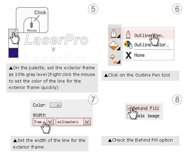
89 G(08)


90 Step 3. Edit the characters for the website Step 4. Combine the 3D images After finishing the production for each of the objects, you may proceed with the combination of the objects. The combined graphic may be output with the laser engraver. Output the 3D graphic After selecting the graphic to be output, set the Mode as 3D Mode in the driver. After setting the engraving parameters, output the 3D graphic G(08)


 and then engrave once again to achieve the better finish.")
91 Tips for engraving 3D graphics LaserPro Application Lab provides a few reminders that may require your attention during the 3D engraving in order to improve the result of the engraving. Turn on the Air Assist function When the engraving is done along with Air Assist, the depth of the engraving would be deeper. Set Air assist inside the driver by checking the box. Polish Dust will accumulate during the engraving when acrylic is engraved. The acrylic may be polished with Polish after the engraving. After the processing, don t remove the engraved object. Use the Control Panel to lower the platform (for about 7~8 mm) and then engrave once again to achieve the better finish. After engraving the wooden objects, please use a toothbrush with some clean water to remove the dust on top of the object G(08)


92 6.5 Modify Image Settings of A Picture for Better Engraving Quality 1. Connect your digital camera to the computer by USB cable. 2. Download the picture from the digital camera to the computer 3. Select the picture that you want to engrave. 4. Import the image from the folder where the picture is located by selecting File/Import 5. Convert the image to Bitmap by selecting the image and click on Bitmaps/Convert to Bitmap G(08)
 and Resolution to 300 dpi")

93 6. Change the Bitmap settings by setting Color to Grayscale (8-bit) and Resolution to 300 dpi and click OK. 7. Finally, Invert the image by selecting Effects/Transform/Invert G(08)


94 8. Now you are ready to output the modified image by clicking File/Print G(08)
95 NOTE This instruction is a simple example for general use. There are many tips and tricks to achieve a good engraving quality. It takes a lot of practice and experience to achieve a good engraving quality. Different picture may need different modifications and different material may need different parameters G(08)
96 Chapter VII - Optional Items When purchasing the LaserPro X252RX & X380RX from your local authorized GCC distributor, you will be provided a chance to purchase optional items to enhance your experience with your system. If anytime after the purchase of your X252RX & X380RX, would you like to purchase any optional item, please contact your local authorized GCC distributor. 7.1 Fume Extraction System Option To properly remove dust, vaporized materials and chemical smoke from the working area and machine, it is necessary to install a suitable Fume Extraction system. The Fume Extraction system and other components are readily available from your local authorized GCC distributor or you can elect to purchase and install one yourself with components found at your local industrial supply store. LaserPro's Fume Extraction Systems are specifically designed to prevent personnel from inhaling hazardous fumes and dust generated by the laser process. Available for all LaserPro engravers, the LaserPro Fume Extraction System represents the latest in fume extraction and odor reduction technology for all types of applications. Quiet operation, high vacuum capacity, compact design and long life expectancy are but a few outstanding features. Each LaserPro Fume Extraction System is powered by a maintenance-free, continuousrunning turbine. In order to ensure personnel safety and legal compliance, the LaserPro Fume Extraction System is CE-compliant for Europe.To purchase a LaserPro Fume Extraction System, contact your local authorized GCC distributor INSTALLATION (Self-Assembled Unit): 1) Purchase an exhaust system at your local industrial supply store, we recommend you have a contractor install the exhaust system. We highly recommend you install the exhaust system outside of the building for both noise considerations and if it does not possess filtering capabilities. 2) Mount the exhaust system in an obvious and accessible location, not too far from the X252RX & X380RX, so it can be routinely switched on prior to laser engraving. The maximal distance you should mount the exhaust system away from the X252RX & X380RX depends on the blower s vacuum capacity. We recommend you consult with the vendor regarding the unit s vacuum force, maximal distances, based on the available models. 3) Connect rigid and smooth walled tubing such as PVC or sheet metal with an 8 diameter to the ventilation opening located on the rear side of the X252RX & X380RX. (As shown in the picture below). Try to keep this tubing as straight as possible as bends reduce the exhaust efficiency. Use the appropriate sized tube clamps and sealants to ensure a tight and secure attachment. Exhaust outlet G(08)

97 7.2 Air Compressor Option (220V Only) Specifically designed for laser engravers, the air compressor utilizes an oil-free diaphragm. The air compressor helps eliminate harmful and potentially damaging moisture from the laser optics, maximizing laser optic life. In addition the air compressor provides the optimal air flow to the SmartAIR nozzles to minimize flaming, suppress working temperatures, and blow away dust and particle byproducts generated from the laser process. ¼ Air Inlet Tubing Power Cord A Power Cord B INSTALLATION: 1) Remove the plugs on the air compressor to expose the air inlets. 2) Fasten the included air tube fastener valve to the outgoing air inlet (indicated by 2a) and the air filter into the ingoing air inlet (indicated by 2b). 2b Plugs 2a 3) Connect a ¼ tubing to the air tube fastener valve on the air compressor. NOTE It is important that the ¼ air tubing has clean, straight cuts on each end. Jagged or slanted cuts will not produce adequate sealing capabilities. 4) Locate the air tube valve positioned towards the front side of X252RX & X380RX. As indicated below: G(08)


98 5) Take the unattached end of the ¼ air tubing (other end already connected to air compressor) and connect it to the air tube connector on the air assist valve. Make sure you press down on the air tube fastener when inserting the ¼ air tubing, to form a tight, secure attachment as indicated in the diagram below. Air Flow Regulator: Turn Clockwise to increase airflow Turn Counter- Clockwise to decrease airflow Air Tube Fastener Air Tube Connector 6) Plug the air compressor to the power outlet on laser machine to control the air assist function through laser driver and firmware. <X252 Air Compressor Connection Power Outlet> Plug the external 220V air compressor to this power outlet to control the air assist function by laser machine driver and firmware G(08)
, before you turn on and utilize the air compressor.")
. The air nozzle under the laser head should emit a steady flow of air.")

99 <X380 Air Compressor Connection Power Outlet> Plug the external 220V air compressor to this power outlet to control the air assist function by laser machine driver and firmware 7) Congratulations, you have finished setting up the air compressor. Make sure you have the proper SmartAIR nozzle installed (depending on your application), before you turn on and utilize the air compressor. OPERATION: 1) Switch on the air compressor unit and make sure that the airflow regulator on the air assist valve is opened (turn clockwise to increase the airflow, counter-clockwise to decrease the airflow). The air nozzle under the laser head should emit a steady flow of air. With the SmartAIR nozzle and air compressor properly installed and operating, all configurations and settings relating to air-assist functions are controlled through the LaserPro X252RX & X380RX print driver and hardware control panel. Please refer to the LaserPro X252RX & X380RX PEN page on print driver section of this manual for details on how to enable and configure air-assist functionalities. 7.3 SmartBOX Option The SmartBOX is an innovative combination of a cutting box, honeycomb table, and material support stands. During the cutting and engraving process, unwanted scrap, dust, and vapor byproducts are left behind. The cutting box collects the larger scrap byproducts while venting out the smaller dust particles, vapors, and smoke to minimize excess buildup on the machine, worktable, and your project. The SmartBOX allows you to maintain a clean worktable and minimizes backside burning of your media, whether you are working with thick and firm materials or thin and flexible materials. SmartBOX Components Cutting Box Honeycomb Table/ Aluminum Grid Cutting Table G(08)


100 Material Support Stands Thumb Screws It is highly recommended that you use different setups of the SmartBOX depending on the physical properties of the material you will be working with. Here is the recommended SmartBOX component setups based on your working material. Application Component Honeycomb Table/ Aluminum Grid Cutting Table Material Support Stands Cutting Box Thin, Flexible Materials Required Required Not Required Thick, Firm Materials Required Not Required Required Action Engraving Light cutting Thick cutting Thin textile/fabric module Suggestion setups NO SmartBOX Honeycomb table/ Aluminum Grid Cutting Table Cutting box + Support SmartBOX NOTE Advanced users may choose to try other component setups to suit their particular engraving / cutting techniques or working material. Feel free to explore different ways to setup the various SmartBOX components to adapt to the results you wish to achieve. INSTALLATION / OPERATION (Cutting Box and Honeycomb Table): 1) Open the front pass-through door and lower the X252RX & X380RX s worktable to the lowest possible position through the X252RX & X380RX control panel. 2) Insert the cutting box and attached honeycomb table through the open front pass-through door onto the worktable, with the Fume Extraction opening facing towards the back end of the X252RX & X380RX. Ensure the rear and left side of the cutting box is aligned flush to the edges of the left and right rulers on the worktable. 3) Open the honeycomb table to find the four screw holes at the bottom of the cutting box. With the included thumbscrews, secure the cutting box to the work table and close the honeycomb table. 4) [OPTIONAL] If you have an Fume Extraction system option installed, then you will need to attach the Fume Extraction system s pipe connector to the SmartBOX s Fume Extraction opening from the X252RX & X380RX s rear side. (For detailed instructions to setup the Fume Extraction system, please see the FUME EXTRACTION UNIT section in section 7.1). Congratulations, you are now ready to position your thin, flexible materials on top of your honeycomb table / cutting box and start working. INSTALLATION / OPERATION (Cutting Box and Material Support Stands): 1) In order to use the cutting box along with the material support stands, you must first remove the honeycomb table from the cutting box. Before you position the cutting box in the LaserPro X252RX & X380RX, first unscrew the screws that attach the hinges of the honeycomb table to the cutting box. 2) Remove the honeycomb table. Please keep in mind the honeycomb table surface is fragile; therefore, it is suggested to keep it in a safe place G(08)
 Insert the cutting box through the open front pass-through door onto the worktable, with the Fume Extraction opening facing towards the back end of the LaserPro X252RX & X380RX.")

101 3) Open the front pass-through door and lower the LaserPro X252RX & X380RX s worktable to lowest possible position through the X252RX & X380RX control panel. 4) Insert the cutting box through the open front pass-through door onto the worktable, with the Fume Extraction opening facing towards the back end of the LaserPro X252RX & X380RX. Ensure the rear and left side of the cutting box is aligned flush to the edges of the left and right rulers on the worktable. 5) Find the four screw holes at the bottom of the cutting box. With the included thumbscrews, secure the cutting box to the worktable. 6) On the front right hand side of the cutting table, there will be a metal guard, which must be swiveled so that it is perpendicular to the front side of the cutting table (as shown in the picture below). This allows the LaserPro X252RX & X380RX to properly account for the extra height the cutting table adds to the cutting table. CAUTION Damage may occur to the system if you try to raise the work table without proper setting of the metal guard. 7) Now position the included material support stands so they support the thick, firm material you will be working with, while avoiding the laser path. In other words, avoid placing the support stands underneath any section of the material that will be lasered, especially during laser cutting. 7.4 SmartAIR Fine / Ultra Nozzles Option The SmartAIR Fine and Ultra Nozzles minimize flaming, suppress working temperatures, and blow away dust and particle byproducts generated from the laser process. The SmartAIR Fine Nozzle is recommended for engraving or cutting thin material such as textile. The smaller caliber nozzle is positioned closer to the object for a concentrated blast directed over a small area to eliminate burning on the cutting edge. The vertical design of the SmartAIR Fine Nozzle produces a concentrated airflow to blow away dust and unwanted residue, leaving a clean product surface. The SmartAIR Ultra Nozzle is recommended for cutting thick material such as acrylic. The larger caliber nozzle produces strong airflow over a wider area to prevent flaming when the laser is cutting at slower speeds. NOTE The LaserPro X252RX & X380RX comes standard with the SmartAIR Standard Nozzle, but for specialized jobs on specific materials, we highly recommend the use of the SmartAIR Fine or Ultra Nozzles. INSTALLATION: 1) Unscrew the thumbscrews securing the front plate of the laser head, and remove the faceplate. 2) Remove the currently installed nozzle by simply sliding it outwards (towards you). 3) With either the SmartAIR Fine or Ultra Nozzle, simply slide into the slot (where you removed the original nozzle), with the pointed end face down. 4) Position the faceplate back onto the laser head and screw the thumbscrews back into place G(08)
102 OPERATION: 1) With the air compressor unit and applicable SmartAIR Nozzle properly installed. Switch on the air compressor unit and make sure that the airflow regulator on the air assist valve is opened (turn clockwise to increase the airflow, counter-clockwise to decrease the airflow). The air nozzle under the laser head should emit a steady flow of air. 2) With the SmartAIR nozzle and air compressor properly installed and operating, all configurations and settings relating to air-assist functions are controlled through the LaserPro X252RX & X380RX print driver and hardware control panel. Please refer to the LaserPro X252RX & X380RX print driver and graphic control panel sections of this manual for details on how to enable and configure air-assist functionalities. 7.4 Rotary Attachment Option The rotary attachment option provides the X252RX/ X380RX with the ability to engrave on cylindrical or spherical objects. In addition to the standard X, Y, Z axis, the rotary attachment allows for a fourth axis which rotates your object 360 to allow for engraving on cups, wine glasses, and even balls. Medium Rotary Attachment for X252RX: Work Piece Limitations Maximum Length Maximum Loading Weight 450 mm (17.71 inches) 4 kg (8.8 lbs.) Minimum Inner Diameter (Large conical fixture) 50 mm (1.96 inches) Maximum Inner Diameter (Large conical 76 mm (2.99 inches) fixture) Minimum Inner Diameter (Small conical fixture) 12 mm (0.47 inches) Maximum Inner Diameter (Small conical fixture) Maximum Outer Diameter 46 mm (1.8 inches) 176 mm (6.9 inches) Large Rotary Attachment for X380RX: Work Piece Limitations Maximum Length Maximum Loading Weight 650 mm (25.59 inches) 4 kg (8.8 lbs.) Minimum Inner Diameter (Large conical fixture) 50 mm (1.96 inches) Maximum Inner Diameter (Large conical 76 mm (2.99 inches) fixture) Minimum Inner Diameter (Small conical fixture) 12 mm (0.47 inches) Maximum Inner Diameter (Small conical fixture) Maximum Outer Diameter 46 mm (1.8 inches) 176 mm (6.9 inches) G(08)
103 Exchange the Conical Fixtures: A. Remove the 2 screws shown in the picture below. B. Detach the circular cylindrical cone by moving it in the direction of the arrow as shown below. C. Assemble the smaller conical fixture onto the rotary attachment as shown below G(08)
 Turn off the power of the engraver before installing the Rotary attachment.")
104 D. Use the flat surface as shown in picture below as a reference point and tighten the first screw against it. After doing so, tighten the second screw and the rotary attachment is ready for use. Flat surface 1. Tighten this against the flat surface 2. Tighten the second screw INSTALLATION: 1) Turn off the power of the engraver before installing the Rotary attachment. 2) Set the rotary attachment onto the engraving table so that the bottom mounting screws correspond to the positional holes on the engraving table. In addition, the top end of the rotary attachment must be leveled against the engraving table with the rotary s positional indicator (center point of the top of the rotary attachment) aligned to the center position on the engraver s vertical axis. 3) With the rotary attachment properly positioned, tighten the mounting screws to secure the rotary attachment. 4) Open the front panel of the X252RX/ X380RX and connect the rotary attachment cable to the rotary attachment port located inside the X252RX/ X380RX's front panel (shown in the picture below). Rotary Attachment Port 5) Close the front panel. 6) The rotary attachment is now properly installed. Power on the X252RX/ X380RX and the rotary attachment will be automatically detected and the engraving table will automatically move to its lowest position. 7) Despite the dummy-proof installation design, please ensure that the device is installed correctly before turning on the machine G(08)
105 OPERATION: 1) Use a ruler to measure the diameter (at the point on the work piece you will be engraving) and length of the work piece you will be engraving. Make a record of this. 2) Load the work piece onto the rotary attachment by first listing the lever on the rotary attachment, unlocking the adjustable end of the rotary attachment. Slide the adjustable end to accommodate the length of the work piece. Load the working piece by centering the open end of the work piece against the rubber wheel and slide the adjustable end to fit the bottom of work piece firmly. Now simply lower the lever to secure the work piece with the rotary attachment. CAUTION If your work piece is small, please apply 4" focal lens for operation to prevent the lens carriage from colliding with the rotary attachment. 3) Prepare the graphic you would like to engrave with the rotary attachment and go to the Paper Page of the print driver. NOTE Please refer to section 5.2 of the reference manual for complete instructions on how to use the X252RX/ X380RX's Print Properties. 4) From the Paper Page, the first thing you must do is to check the Rotary Fixture. The Paper Size options and Rotary Parameter will change to allow for proper input based on your rotary attachment. 5) Under Paper Size, the X value represents the length of your working piece. Enter the length of your work piece in this field. 6) Under Paper Size, the Diameter value represents the diameter of your working piece (at the position you wish to engrave). Enter the diameter of your work piece in this field. Again remember the proper diameter value would be the diameter location on your work piece you will be engraving. 7) Under Rotary Parameter, the Offset value represents distance from the open end of your work piece to the base of the padded rubber wheel. This value will be displayed on the X252RX/ X380RX s LCD panel. Enter the proper offset value in this field. 8) Your X252RX/ X380RX print driver settings are now properly set. Manually position the laser carriage to the proper X / Y location on the object you will be engraving and position the auto focus pin over the area to be engraved on your work piece. Hit the Auto Focus button and the X252RX/ X380RX will now properly focus at the location to be engraved. 9) Go back to the X252RX/ X380RX Print Driver to print your design and let the engraving begin. 10) Despite the dummy-proof installation design, please ensure that the device is installed correctly before turning on the machine G(08)
106 Chapter VIII Basic Maintenance Keeping your LaserPro X252RX & X380RX clean and well maintained will ensure quality output, consistent reliability, and extended product life. Smoke, dust or residue build-up inside the laser system or the mechanical components can cause a reduction in the laser power, irregularities in the motion system, reduced product life cycle, and a host of other avoidable problems. This section will cover how to perform regular maintenance on the X252RX & X380RX s worktable, motion system, mirrors, and focal lens. The frequency of the cleaning schedule will depend on number of variables such as the types of material you work with, the immediate work environment, the frequency of use, the quality of the exhaust system, etc. WARNING Electrical Shock may occur if you do not turn off and unplug the X252RX & X380RX before cleaning. Damage may occur to the system if you do not turn off and unplug the X252RX & X380RX before cleaning. Always turn off and unplug the X252RX & X380RX before cleaning! 8.1 Suggested Cleaning and Maintenance Supplies Cleaning / Maintenance Tool Soap Solution or All-Purpose Cleaner Paper Towels Cotton Cloth Denatured Alcohol Acetone Vacuum Cleaner with a Flexible Nozzle Light Grade Machine Oil Cotton Swabs Lens Cleaner Lint Free Lens Tissue #2 Phillips Screwdriver Allen Wrench.050 Special notes DO NOT use alcohol on any painted surface, plastic, or the laser system! ONLY to be used on the working table Only to be used in and around the worktable and motion system Supplied 1pc supplied; suggest search locally* Supplied *The recommended lens cleaner is Eclipse Cleaning System Solution from Photographic Solutions or HPLC grade Methanol. Search Eclipse Cleaning System Solution on Amazon or ebay to get the solution locally G(08)
 Turn the power off and unplug the X252RX & X380RX before")
107 Eclipse Cleaning System Solution 8.2 Maintaining the Worktable and Motion System Accessing the Worktable and Motion System Remove the screws of the top of the machine and lift the top off Cleaning the Worktable and Motion System Cleaning the Worktable and Motion System Clean the working table and the motion system on a weekly basis through the following steps: 1) Turn the power off and unplug the X252RX & X380RX before cleaning. 2) Use a vacuum cleaner with a flexible nozzle to remove dust and debris from the worktable and motion system. 3) Apply small amounts of all-purpose cleaner, alcohol, or acetone to a paper or cotton towel to clean the working table. 4) Apply a soap solution, all-purpose cleaner, or alcohol to a paper or cotton towel to wipe down the rails of the motion system. 5) Wait for all cleaning residue to dry completely before plugging in and operating the X252RX & X380RX. CAUTION Never pour or spray alcohol or acetone directly to the working table. Oil, alcohol and acetone can cause fires or smoke build-up if improperly used. TIP Please clean the AutoFocus pin each time after completing the engraved job to make sure the AutoFocus pin is free to move G(08)
108 Lubrication of the X / Y Rails In order to keep the motion system running smoothly, the X / Y rails of the motion system will need lubrication on a weekly basis. Use a small amount of light grade machine grease to a paper or cotton towel and apply to the rails. NOTE Always clean and lubricate the rails after working with materials that produce lots of debris (such as wood). Too much oil applied to the X / Y rails will accelerate the build up of debris. 8.2 Cleaning the Optics System Removing the Mirrors We recommend you check the mirrors once or twice a week to see if they require cleaning. If any debris or smoke residue is present, use the following steps to clean them. NOTE It is highly recommended you remove, clean and replace each mirror one at a time! Refer to section on how to clean the mirrors. The following section will detail how to access and remove each of the four mirrors found on the LaserPro X252RX & X380RX for cleaning. Mirror 1 This mirror is located inside the laser cabinet of the LaserPro X252RX & X380RX. 1) Use a #2 Phillips Screwdriver to open the rear laser cabinet of the LaserPro X252RX & X380RX. 2) Loosen the thumbscrew and remove the dust cover securing the mirror. (As shown in the picture below) G(08)
 Clean the")
 Re-install the mirror")
 Tighten the thumbscrew.")


109 Thumbscrew Thumbscrew Thumbscrew 3) Clean the lens in the proper manner. 4) Re-install the mirror after cleaning. 5) Tighten the thumbscrew. 6) Replace and secure the outer access panel. Mirror 2, 3, 4 These mirrors are located in the worktable area of the LaserPro X252RX & X380RX. Mirror 2 Mirror 3 Mirror G(08)
110 Mirror 2 1) Unscrew and remove the black dust cover covering mirror 2. 2) Unscrew the thumbscrew holding mirror 2 in place. 3) Clean the lens in the proper manner. 4) Re-install mirror 2 after cleaning. 5) Tighten the thumbscrew. 6) Replace and secure the black dust cover. Mirror 3 1) Unscrew the thumbscrew holding mirror 3 in place. 2) Clean the lens in the proper manner. 3) Re-install mirror 3 after cleaning. 4) Tighten the thumbscrew. Mirror 4 1) Unscrew the three thumbscrews (front face of the laser head) securing the laser carriage panel and remove the laser carriage panel to reveal mirror 4 and the focal lens. 2) Loosen the top thumbscrew to remove mirror 4 (as shown in the picture below). Reflection mirror Focus lens 3) Clean the lens in the proper manner. 4) Re-install mirror 4 after cleaning. 5) Tighten the top thumbscrew. 6) Reinstall the laser carriage panel and tighten the three thumbscrews Cleaning the Mirrors After you have removed each mirror, you will want to inspect each mirror for scratches, smoke residue, or debris. If any residue or debris is present, use the following steps to clean the mirror. 1) Hold the mirror with the reflective side up, without touching the reflective side of the mirror (DO NOT apply any finger pressure or any other cleaning solutions to the mirror surface). 2) Drape a new sheet of lens tissue over the mirror G(08)
 Pull the tissue across the mirror in only one direction. 5) Repeat the cleaning processes if the mirror is not completely clean after the first attempt.")
 Unscrew the three thumbscrews (front face of the laser head) securing the laser carriage panel and remove the laser carriage panel to reveal the focal lens.")
111 3) Apply a few drops of lens cleaner on the tissue covered mirror (apply enough so that the tissue absorbs just enough to cover the mirror surface). 4) Pull the tissue across the mirror in only one direction. 5) Repeat the cleaning processes if the mirror is not completely clean after the first attempt. 6) Make sure that the mirror is completely dry before reinstalling it. CAUTION If the center of the mirror is scratched, contact your LaserPro X252RX & X380RX dealer for a replacement Removing and Cleaning the Focal Lens 1) Unscrew the three thumbscrews (front face of the laser head) securing the laser carriage panel and remove the laser carriage panel to reveal the focal lens. 2) Carefully pull out the focal lens (as indicated in the picture below). Focus lens 3) Clean the focal lens with a cotton swab and lens cleaner solution. Be sure to clean both sides of the focal lens (DO NOT apply any finger pressure or other cleaning solutions to the lens surface). 4) After cleaning, use a cotton swab to gently dry the focal lens and lens cover G(08)
Dear Sir or Madam, Sincerely, Leonard Shih President of G.C.C Spirit GE User Manual
 Dear Sir or Madam, Thank you for choosing GCC and the LaserPro Spirit GE. You can be assured that this machine meets all of the highest safety standards while using technological innovations shared by
LaserPro Venus II User Manual 0
 LaserPro Venus II User Manual 0 Content QUICK MENU... 3 Chapter I - INTRODUCTION... 4 1.1 Principles of CO 2 Laser... 4 1.2 Safety... 4 1.3 Precaution... 4 1.4 Fire Precaution... 4 1.5 The Safety Interlock
User Manual. Laser DirectPrint MAC AI Plug-in. Introduction to the. Copyright 2009 GCC,Inc. All Right Reserved.
 User Manual Introduction to the Laser DirectPrint MAC AI Plug-in Copyright 2009 GCC,Inc. All Right Reserved. Table of Contents Chapter 1. Recommended Computer Configuration... 1 1.1 Hardware Compatibility...
NOTICE. For Firmware (V1.1 and later version), when under the. Single File Mode, the file can be repeated if you choose
, when under the. Single File Mode, the file can be repeated if you choose") NOTICE For Firmware (V1.1 and later version), when under the Single File Mode, the file can be repeated if you choose to redo it. After the work is completed, the machine will be back to the STOP status.
NOTICE For Firmware (V1.1 and later version), when under the Single File Mode, the file can be repeated if you choose to redo it. After the work is completed, the machine will be back to the STOP status.
II. INTRODUCTION. Principles of CO 2 Laser. Safety. Precaution. LASER is a Light Amplification by Stimulated Emission of Radiation.
 INDEX Page I. Index 1 II. Introduction 2-4 III. Unpacking...5-7 IV. Basic Maintenance. 8-16 V. Connecting the Laser..17-19 VI Install Driver / Other Software Setup..... 20-30 VII. E6 Software Requirements
WELCOME WHAT S IN THE BOX
 WELCOME Congratulations on purchasing your Visioneer PaperPort flatbed scanner. With your scanner, you can quickly scan paper documents and color photos to place their electronic images on your computer.
Content. UNPACKING...iv. Unpacking inspection...iv QUICK MENU...v LENS and MANUAL FOCUS GAUGE...vi I. INTRODUCTION...vii
 USER MANUAL VENUS Content UNPACKING...iv Unpacking inspection...iv QUICK MENU...v LENS and MANUAL FOCUS GAUGE...vi I. INTRODUCTION...vii Principles of CO 2 Laser...vii Safety...vii Precaution...vii Fire
Rabbit Series Laser Engraving Machine HX3040. User s Manual. 1 Jinan King Rabbit Technology Development Co. Ltd.
 Rabbit Laser Engraving Machine HX3040 User s Manual 1 Preface Thank you for buying our Rabbit Series HX3040 Laser Engraving Machine. You will find it has many nice features including easy operation, high
Flash Stamp Machine T1511M User Manual
 Flash Stamp Machine T1511M User Manual Declaration of conformity (Europe only) We, Trodat GmbH Linzer Straße 156 A-4600 Wels hereby declare that the Flash Stamp Machine model T1511M is CE certified respectively
F400 QUICK-START GUIDE
 F400 QUICK-START GUIDE PLEASE READ THIS DOCUMENT BEFORE OPERATING YOUR PRINTER Revision 10-1/31/18 Page 1 Table of Contents 1. Introduction... 3 2. What s in the Box... 3 3. Unboxing Your F400... 4 4.
College for Creative Studies Alfred Taubman Center-Model Shop Laser Usage Guide
 College for Creative Studies Alfred Taubman Center-Model Shop Laser Usage Guide LASER CUTTER USER GUIDE Introduction The College for Creative Studies Model Shop is equipped with 1 ILS12.150D Universal
Mini Photo Printer User Manual
 Mini Photo Printer User Manual CONTENTS SAFETY INFORMATION PACKAGE CONTENT PRINTER SETUP A) Charge Printer B) Power On C) Load Paper INSTALLING APP PARING MOBILE DEVICE & CANON MINI PRINT USER INTERFACE
OPERATION MANUAL MIMAKI ENGINEERING CO., LTD.
 OPERATION MANUAL MIMAKI ENGINEERING CO., LTD. http://www.mimaki.co.jp/ E-mail:traiding@mimaki.co.jp D200674 About FineCut for CorelDRAW Thank you very much for purchasing a product of Mimaki. FineCut,
Series 48 Water Cooled Laser & UC-2000 Quick Start Guide
 Important Read all Danger, Warning, Caution terms, symbols, and instructions located in the (Laser Safety Hazard information) sections in the Series 48 Laser Operation Manuals. http://www.synrad.com/synrad/docroot/resources/libraries/manuals
Intro to CO 2 Laser Cutting
 MAKERSPACE Intro to CO 2 Laser Cutting What Can I Do With the CO 2 Laser? CO 2 laser cutters and engravers are excellent for making precise 2-dimensional cuts in a variety of materials, as well as engraving
NOTICE. For Firmware (V1.1 and later version), when under the. Single File Mode, the file can be repeated if you choose
, when under the. Single File Mode, the file can be repeated if you choose") NOTICE For Firmware (V1.1 and later version), when under the Single File Mode, the file can be repeated if you choose to redo it. After the work is completed, the machine will be back to the STOP status.
NOTICE For Firmware (V1.1 and later version), when under the Single File Mode, the file can be repeated if you choose to redo it. After the work is completed, the machine will be back to the STOP status.
Vinyl Cutter Instruction Manual
 Vinyl Cutter Instruction Manual 1 Product Inventory Inventory Here is a list of items you will receive with your vinyl cutter: Product components (Fig.1-4): 1x Cutter head unit complete with motor, plastic
COLE. Cutting Plotter CL365/720/870/1100/1350. Instruction Manual
 COLE Cutting Plotter CL365/720/870/1100/1350 Instruction Manual Contents I. General Safety Rules 1 II. Specifications 2 III. Plotter Components Diagram 3 IV. Assembly Diagram of Plotter Stand 4 V. Loading
TM5. Guide Book. Hardware Version: 2.00 Software Version: 1.62
 TM5 Guide Book Hardware Version: 2.00 Software Version: 1.62 ii Release Date : 2017-07-10 The information contained herein is the property of Techman Robot Corporation (hereinafter referred to as the Corporation).
Installation and Operating Instructions Desk top Laser
 www.katanatrading.com Installation and Operating Instructions Desk top Laser This manual covers the following: A. Unpacking and setup of the engraver B. Installation of Newly Seal software C. Basic operation
Pulstar p100/150 water cooled laser & Flyer 3D System Quick Start Guide
 Important See the Flyer 3D Marking Head and Pulstar p100/150 Laser Operators Manual for complete installation details and instructions. A PDF version is available online at: http://www. synrad.com/manuals/manuals_laser.htm.
RDworks and Basic Rabbit Laser Operation Tutorial
 RDworks and Basic Rabbit Laser Operation Tutorial File Setup Layer color is how the Rabbit Software designates different operations so, regardless of design software, you will want to organize geometry
Mini Photo Printer User Manual
 Mini Photo Printer User Manual CONTENTS SAFETY INFORMATION PACKAGE CONTENT PRINTER SETUP A) Charge Printer B) Power On C) Load Paper INSTALLING APP PARING MOBILE DEVICE & CANON MINI PRINT USER INTERFACE
Film2USB Converter. Quick Start Guide & User s Manual. Model Number F2USB-05
 Film2USB Converter Quick Start Guide & User s Manual Model Number F2USB-05 www.film2usb.com www.clearclicksoftware.com Table of Contents Safety Precautions... 3 Package Contents... 4 Description of Parts...
Operation manual. Thanks very much for purchasing this. cutter/plotter. To ensure you make best use of your machine,
 Operation manual Thanks very much for purchasing this cutter/plotter. To ensure you make best use of your machine, please read this manual carefully and thorughly beforhand. IMMEDIATELY power off the machine
Radio Link Starter Kit
 Radio Link Starter Kit Installation Manual BARTLETT Instrument Co. 1032 Avenue H Fort Madison, IA 52627 319-372-8366 www.bartinst.com Table of Contents Radio Link Starter Kit Manual... 3 System Requirements...
Nikon View DX for Macintosh
 Contents Browser Software for Nikon D1 Digital Cameras Nikon View DX for Macintosh Reference Manual Overview Setting up the Camera as a Drive Mounting the Camera Camera Drive Settings Unmounting the Camera
Diode Pointer Quick Start Guide
 Important Note: Read all Danger, Warning, Caution terms, symbols, and instructions located on our website. The diode pointer provides a safety measure by enabling operators to monitor the location of the
DOCUMENT SCANNER INSTRUCTIONS. Space. Backup. Count Only. New File. Scanner. Feeding Option Manual Auto Semi-Auto
 E FILM F Scanner A Space Count Only New File Feeding Option Manual Auto Semi-Auto Backup DOCUMENT SCANNER INSTRUCTIONS NOTICE q Copyright 2001 by CANON ELECTRONICS INC. All rights reserved. No part of
Operation Manual. Chap. 1 Attention. Please read the attention carefully before operating the machine.
 Chap. 1 Attention Please read the attention carefully before operating the machine. 1. No magnetic devices should be placed in the vicinity of the plotter, specifically the carriage. 2. Prevent from dropping
Firestar f201 laser & Flyer 3D System Quick Start Guide
 Important Note: See the Flyer 3D Marking Head and Firestar f201 Laser Operators Manual for complete installation details and instructions. A PDF version is available Online at: http://www.synrad.com/manuals/manuals_laser.htm.
Radio Link Starter Kit
 Radio Link Starter Kit Installation Manual BARTLETT Instrument Co. 1032 Avenue H Fort Madison, IA 52627 319-372-8366 www.bartinst.com Table of Contents Radio Link Starter Kit Manual... 3 System Requirements...
DC155 Digital Visualizer. User Manual
 DC155 Digital Visualizer User Manual Table of Contents CHAPTER 1 PRECAUTIONS... 4 CHAPTER 2 PACKAGE CONTENT... 6 CHAPTER 3 PRODUCT OVERVIEW... 7 3.1 PRODUCT INTRODUCTION... 7 3.2 I/O CONNECTION... 8 3.3
KoPa Scanner. User's Manual A99. Ver 1.0. SHENZHEN OSTEC OPTO-ELECTRONIC TECHNOLOGY CO.,LTD.
 KoPa Scanner A99 User's Manual Ver 1.0 SHENZHEN OSTEC OPTO-ELECTRONIC TECHNOLOGY CO.,LTD. http://www.ostec.com.cn Content Chapter 1 Start... 1 1.1 Safety Warnings and Precautions... 1 1.2 Installation
Camera. Multi Lens Camera A-427-V. Quick Start Guide
 Camera Multi Lens Camera A-427-V Quick Start Guide 0 About this Manual Multi Lens Camera Quick Start Guide This Manual is applicable to A-427-V Network Camera. The Manual includes instructions for using
OPERATION MANUAL ULS-25PS / ULS-25PSR ULS-50PS / ULS-50PSR
 OPERATION MANUAL ULS-25PS / ULS-25PSR ULS-50PS / ULS-50PSR Universal Laser Systems, Inc. 16008 North 81st Street Scottsdale, AZ 85260 Phone: 602-483-1214 Fax: 602-483-5620 Volume I, Rev. B1 July 1996 This
Handheld Omnidirectional Laser Scanner
 1 i Important Notice No warranty of any kind is made in regard to this material, including, but not limited to, implied warranties of merchantability or fitness for a particular purpose. We are not liable
С 800 CASSIDA C 800 HIGH SPEED COIN COUNTER
 С 800 CASSIDA C 800 HIGH SPEED COIN COUNTER This manual contains important information on safety measures and operational features. Please read it carefully before operating your coin counter, and keep
Rotary Fixture M/V/X CLASS LASER SYSTEMS. Installation and Operation Instructions
 Rotary Fixture M/V/X CLASS LASER SYSTEMS Installation and Operation Instructions 02/01/2000 Introduction The Rotary Fixture controls in the Printer Driver are used along with the optional Rotary Fixture
Firestar vi30/40 Dual Cooled Laser Quick Start Guide
 Important See the Firestar vi30/40 Operators Manual for complete installation details and instructions. A PDF version is available online at: http://www.synrad.com/synrad/docroot/resources/libraries/manuals.
Laser Alignment. Step-By-Step for the Epilog Mini / Helix Manufactured From 2004 to 2009 (8000 Model)
") Laser Alignment Step-By-Step for the Epilog Mini / Helix Manufactured From 2004 to 2009 (8000 Model) 1 Laser alignment can be done if any of the following applies to you. You are experiencing a general
Laser Alignment Step-By-Step for the Epilog Mini / Helix Manufactured From 2004 to 2009 (8000 Model) 1 Laser alignment can be done if any of the following applies to you. You are experiencing a general
HP Latex 1500 Printer HP Latex 3000 Printer Series. Double-sided Day Night Kit User Guide
 HP Latex 1500 Printer HP Latex 3000 Printer Series Double-sided Day Night Kit User Guide Copyright 2016 HP Development Company, L.P. Edition 1 Legal notices The information contained herein is subject
FIBERMARK LASER SYSTEM MANUAL MODEL Register your system now for driver update notifications and FREE files! EPILOGLASER.
 FIBERMARK LASER SYSTEM MANUAL MODEL 8000 Register your system now for driver update notifications and FREE files! EPILOGLASER.COM/REGISTER Technical Support: +1 (303) 215-9171 Knowledge Base: support.epiloglaser.com
Start Here. Installing your Microtek ScanMaker 9800XL Plus PC:
 Start Here Installing your Microtek ScanMaker 98XL Plus Step : Unpack Contents. Optional package items depend on the scanner configuration that you purchased. Unpack your scanner package and check for
Operating Guide. HT25 Multi Side Tabber & Stamp Affixer. HASLER America s better choice. Mailing Systems And Solutions
 Operating Guide Mailing Systems And Solutions HASLER America s better choice HT25 Multi Side Tabber & Stamp Affixer An ISO 9001 Quality System Certified company Rev. 8/25/2010 Please record the following
DC162 Digital Visualizer. User Manual. English - 1
 DC162 Digital Visualizer User Manual English - 1 Chapter 1 Precautions Always follow these safety instructions when setting up and using the Digital Visualizer: 1. Please do not tilt the machine while
SUNNY BEAM REPEATER Transmission Range Increase for Sunny Beam
 SUNNY BEAM REPEATER Transmission Range Increase for Sunny Beam User Manual SBeamRep-BEN091911 98-0002611 Version 1.1 EN SMA Solar Technology AG Table of Contents Table of Contents 1 Notes on this Manual..............................
Supplement. ScanMaker i280 features, scenarios, and information. Getting to Know Your ScanMaker i280
 Supplement ScanMaker i280 features, scenarios, and information Getting to Know Your ScanMaker i280 The ScanMaker i280 is a high resolution scanner for reflective scanning. It features 4800 x 9600 dpi,
DigiScope II v3 TM Aperture Scope User s Manual
 DigiScope II v3 TM Aperture Scope User s Manual Welcome Thank you for choosing DigiScope II v3 TM Aperture scope! The DigiScope II v3 TM Aperture Scope is an exciting new device to Capture and record the
Start Here. Installing your Microtek ScanMaker i280
 Start Here Installing your Microtek ScanMaker i280 Step 1: Unpack Contents Unpack your scanner package and check for major components. 1. ScanMaker i280 scanner 2. Hi-Speed USB cable 3. Software CDs/DVDs
RAZER GOLIATHUS CHROMA
 RAZER GOLIATHUS CHROMA MASTER GUIDE The Razer Goliathus Chroma soft gaming mouse mat is now Powered by Razer Chroma. Featuring multi-color lighting with inter-device color synchronization, the bestselling
Firestar v Series air cooled laser & Flyer 3D System Quick Start Guide
 Important Note: See the Flyer 3D Marking Head and Firestar v Series Laser Operators Manual for complete installation details and instructions. A PDF version is available Online at: http://www.synrad.com/manuals/manuals_laser.htm.
User Manual. For MAC
 User Manual For MAC A3 Scanner with The TWAIN Driver (For Macintosh) English User Manual Contents Preface Chapter One Setting Up the Scanner 1 System Requirements... 1 Unpacking the Scanner... 2 The Scanner
Operating Manual. itech IMPAXX Digital Monument Engraver
 Operating Manual itech IMPAXX Digital Monument Engraver Copyright 2013 Allen Datagraph Systems - All Rights Reserved Manual Date August 2013 Congratulations on your new purchase! Thank You for Selecting
Firestar f201 laser & Flyer 3D System Quick Start Guide
 Important Note: See the Flyer 3D Marking Head and Firestar f201 Laser Operators Manual for complete installation details and instructions. A PDF version is available Online at: http://www.synrad.com/manuals/manuals_laser.htm.
HPC LASER LTD LS ^0«0 MANUAL HPC LASER LTD - NEVER LEAVE YOUR MACHINE UNATTENDED WHEN WORKING
 1 HPC LASER LTD LS ^0«0 MANUAL HPC LASER LTD - NEVER LEAVE YOUR MACHNE UNATTENDED WHEN WORKNG TABLEO FC O N T E N T S LASERSAFETY ELECTRCALS A F E T Y FRESAFETY Section 1: Unpacking your engraver Section
Universal Laser Systems VLS3.50 Laser Cutter/Engraver. Safety and Operation Guide
 Universal Laser Systems VLS3.50 Laser Cutter/Engraver Safety and Operation Guide Table of Contents System Specifications 2 General Capability 3 Laser Cutter Safety 3 General Safety 3 Fire Protocol 4 Laser
Kaitian - Model: Engraving & Cutting Laser System CM1309SH 1 Head One (01) KT Laser tube Watts
 KT Laser tube Watts") ESTIMATE No.: Los Angeles, Client: Contact: Telephone: C e l l - Phone: E-mail: Address: City, State: Fax: Zip Code: Country: Kaitian - Model: Engraving & Cutting Laser System CM1309SH 1 Head One (01)
ESTIMATE No.: Los Angeles, Client: Contact: Telephone: C e l l - Phone: E-mail: Address: City, State: Fax: Zip Code: Country: Kaitian - Model: Engraving & Cutting Laser System CM1309SH 1 Head One (01)
WIRELESS Energy Monitor - Smart Meter
 Energy saving made simple MONITOR CONTROL SAVE WIRELESS Energy Monitor - Smart Meter Monitors your electricity use and cost in real time Instruction Manual EW4500 IMPORTANT Please retain your Instruction
Start Here. Unpack Contents. Install Software
 Start Here Installing your Microtek ArtixScan DI 5230/5240/5250/5260 & ArtixScan TS 540T Unpack Contents Unpack your scanner package and check for major components. 1. Scanner 2. Hi-Speed USB cable 3.
reference guide reference guide reference guide
 hp photosmart 240 series reference guide reference guide reference guide contents 1 welcome..................................... 1 find more information.............................. 1 what s in the box.................................
Microscopy from Carl Zeiss
 Microscopy from Carl Zeiss Contents Page Contents... 1 Introduction... 1 Starting the System... 2 Introduction to ZEN Efficient Navigation... 5 Setting up the microscope... 10 Configuring the beam path
Reference Guide Brief explanations for routine operations
 Reference Guide Brief explanations for routine operations DCP-T30 DCP-T50W DCP-T70W Brother recommends keeping this guide next to your Brother machine for quick reference. Online User's Guide For more
Laser Cutter Buying Guide. The ultimate guide for education. The Ultimate Guide to Buying a Laser Cutter for Education
 Laser Cutter Buying Guide The ultimate guide for education Laser Cutter Buying Guide Laser cutters are a great addition to a Design and Technology workshop; encouraging students to familiarise themselves
p250 Flyer 3D System Quick Start Guide
 p250 Flyer 3D System Quick Start Guide Important Note: See the Flyer 3D Marking Head and p250 Laser Operators Manual for complete installation details and instructions. A PDF version is available Online
MRI SIMULATOR PST OPERATOR MANUAL
 MRI SIMULATOR PST-100355 OPERATOR MANUAL MRI Simulator Operator Manual PST-100444 Rev 7 Copyright Copyright 2012 Psychology Software Tools, Inc. All rights reserved. The information in this document is
Universal Camera Registration User Guide for ILS 9.75 & 12.75
 User Guide for ILS 9.75 & 12.75 www.ulsinc.com Overview Camera Registration allows the laser system to automate the alignment of a vector path with the material for the purpose of tightening process control
SKF TKTI. Thermal Camera Software. Instructions for use
 SKF TKTI Thermal Camera Software Instructions for use Table of contents 1. Introduction...4 1.1 Installing and starting the Software... 5 2. Usage Notes...6 3. Image Properties...7 3.1 Loading images
MANUAL. Textron Motors Diagnostic Tool. This manual is valid for the following Textron Motors Diagnostic Tool:
 MANUAL Textron Motors Diagnostic Tool This manual is valid for the following Textron Motors Diagnostic Tool: 0507 TD0507_HB Rev F 6..05 en_english Read the manual before performing the task on the engine.
English QT V01 CANON INC PRINTED IN CHINA
 English Quick Start Guide English Please read this guide before operating this scanner. After you finish reading this guide, store it in a safe place for future reference. Table of Contents Package Contents...
ScanGear CS-U 5.6. for CanoScan FB1210U Color Scanner. User s Guide
 ScanGear CS-U 5.6 for CanoScan FB1210U Color Scanner User s Guide Copyright Notice Copyright 2000 Canon Inc. This manual is copyrighted with all rights reserved. Under the copyright laws, this manual may
Please read this manual before using the printer. Please keep this manual within easy reach for quick reference.
 INSTRUCTION MANUAL Please read this manual before using the printer. Please keep this manual within easy reach for quick reference. GARMENT PRINTER support homepage http://www.brother.com/usa/garmentprinters/
Pulsed Fiber Laser on Flatbed Technology FP 100 / FP 300. High Performance Marking Solutions
 Pulsed Fiber Laser on Flatbed Technology High Performance Marking Solutions your needs decide Your advantages at a glance Your Investment Your Return Entry-level model for marking metals and plastics Almost
Fixed Wall Arm. Installation Guide. Part number Rev E 2012 PolyVision Corporation All rights reserved
 Fixed Wall Arm Installation Guide Part number 2002003-001 Rev E 2012 PolyVision Corporation All rights reserved Table of contents Important Safety Instructions... 3 Overview... 4 Important considerations...
23070 / Digital Camera Owner s Manual
 23070 / 23072 Digital Camera Owner s Manual 2007 Sakar International, Inc. All rights reserved. 2007 Crayola Windows and the Windows logo are registered trademarks of Microsoft Corporation. All other trademarks
F410 QUICK-START GUIDE
 F410 QUICK-START GUIDE PLEASE READ THIS DOCUMENT BEFORE OPERATING YOUR PRINTER Revision 3-5/4/18 Page 1 1. Table of Contents 1. Table of Contents... 2 1. Introduction & Getting Support... 3 2. What s in
Diode Pointer Quick Start Guide
 Important Note: Read all Danger, Warning, Caution terms, symbols, and instructions located in the (Safety & Hazard information) on our website. Reference the Diode Pointer Specifications located on our
User s manual PROUD TO BE YOUR GUIDE TM GB NL F E
 User s manual PROUD TO BE YOUR GUIDE TM GB NL F E Table of contents INTRODUCTION............................. 2 DESCRIPTION OF THE DRIVE CONTROL PRO........... 2 OVERVIEW BEFORE GETTING STARTED..............
Print Head Installation Guide
 Print Head Installation Guide MCS Raptor 6 (MCS Eagle AMS Software) is copyright of MCS Incorporated. 2015 MCS Incorporated. 1 Contents Tools... 4 Warnings... 4 Introduction... 4 Section One - Pillar Installation...
CHROMACAL User Guide (v 1.1) User Guide
 User Guide") CHROMACAL User Guide (v 1.1) User Guide User Guide Notice Hello and welcome to the User Guide for the Datacolor CHROMACAL Color Calibration System for Optical Microscopy, a cross-platform solution that
CHROMACAL User Guide (v 1.1) User Guide User Guide Notice Hello and welcome to the User Guide for the Datacolor CHROMACAL Color Calibration System for Optical Microscopy, a cross-platform solution that
ZING 16 / 24 LASER SYSTEM MANUAL MODEL ORIGINAL INSTRUCTIONS
 ZING 16 / 24 LASER SYSTEM MANUAL MODEL 10000 ORIGINAL INSTRUCTIONS Register your system now for driver update notifications and FREE files! EPILOGLASER.COM/REGISTER Technical Support: +1 (303) 215-9171
EBA 430 E EBA 430 EP. Operating Instructions
 EBA 430 E EBA 430 EP Operating Instructions EBA 430 E EBA 430 EP Dear customer, Thank you for choosing a paper cutting machine from EBA. With the purchase of this quality product you can be sure you have
Figure 1 The Raith 150 TWO
 RAITH 150 TWO SOP Figure 1 The Raith 150 TWO LOCATION: Raith 150 TWO room, Lithography area, NanoFab PRIMARY TRAINER: SECONDARY TRAINER: 1. OVERVIEW The Raith 150 TWO is an ultra high resolution, low voltage
APPLICATION NOTE. Computer Controlled Variable Attenuator for Lasers. Technology and Applications Center Newport Corporation
 APPLICATION NOTE Computer Controlled Variable Attenuator for Lasers 31 Technology and Applications Center Newport Corporation Computer Controlled Variable Attenuator for Lasers This application note describes
Windows INSTRUCTION MANUAL
 Windows E INSTRUCTION MANUAL Contents About This Manual... 3 Main Features and Structure... 4 Operation Flow... 5 System Requirements... 8 Supported Image Formats... 8 1 Installing the Software... 1-1
RS3040A Mini Laser Engraving Machine User Manual
 RS3040A Mini Laser Engraving Machine User Manual Thank you very much for buying RS3040A laser engraving machine. In order to make sure that your laser engraving machine can work steadily for a long period
HP Advanced Profiling Solution Quick Start Guide
 HP Advanced Profiling Solution Quick Start Guide Welcome to the! You have just successfully installed HP APS on your computer and clicked on the Quick Start Guide button in your HP APS Control Center.
Welcome 1. Precaution
 Table of Contents EN Precaution....2 Preparation.. 4 Standard accessories....4 Parts Names & Functions...5 Computer System requirements.... 6 Technical Specifications 7 Install the software.. 7 Start Microscope.8
C-200 Laser Engraving and Cutting System Operation Manual
 C-200 Laser Engraving and Cutting System Operation Manual Manufactured by: Universal Laser Systems, Inc. 16008 North 81st Street Scottsdale, AZ 85260 USA Customer Support Department Phone: 480-609-0297
Nikon D7100 Camera Kit. -Checklist and Operations Manual-
 Airborne Digital Reconnaissance System (ADRS) Nikon D7100 Camera Kit -Checklist and Operations Manual- V4.2 October 21, 2014 National Headquarters, Civil Air Patrol 2 1.0 Equipment Pre-Mission Check 1.1
Quick Start Guide. Setup and Scanning. Try the Additional Features. English
 English Quick Start Guide Be sure to install the software programs before connecting the scanner to the computer! Setup and Scanning Check the Package Contents p.3 Install the Software Windows Macintosh
OVA-50 Optical Variable Attenuator User s Manual
 OVA-50 Optical Variable Attenuator User s Manual Shineway Technologies, Inc. All rights reserved. Safety Instructions The WARNING sign denotes a hazard. It calls attention to a procedure, practice, or
RENISHAW INVIA RAMAN SPECTROMETER
 STANDARD OPERATING PROCEDURE: RENISHAW INVIA RAMAN SPECTROMETER Purpose of this Instrument: The Renishaw invia Raman Spectrometer is an instrument used to analyze the Raman scattered light from samples
User Manual. Digital Compound Binocular LED Microscope. MicroscopeNet.com
 User Manual Digital Compound Binocular LED Microscope Model MD82ES10 MicroscopeNet.com Table of Contents i. Caution... 1 ii. Care and Maintenance... 2 1. Components Illustration... 3 2. Installation...
Witbox 2. Quick start guide
 Witbox 2 Quick start guide Welcome. Thank you for choosing us. This manual will help you to use your new 3D printer correctly. Welcome to the world of Witbox 2. How do I use this manual? To make sure that
Installation & User Manual Micro-Image Capture 7
 Installation & User Manual Micro-Image Capture 7 Ver1.2016 Product Warranty Quality Assurance Every Micro-Image Capture system passes quality assurance tests including focus, resolution quality and mechanical
The CO2 Sensor Calibration Kit
 The CO2 Sensor Kit For use with all BAPI CO 2 Sensors Instruction Manual CO 2 Kit Product Identification and Overview BAPI s CO 2 Sensor Kit is designed to calibrate and verify the operation of all BAPI
Combo Scanner. User Manual
 Combo Scanner User Manual I. Unpack the Combo Scanner Backlight Holder Combo Scanner Business card Fixture Photo/Business Card Holder User Manual Quick Installation Guide Note This Combo Scanner supports
L4 Series Operator Manual
 L4 Series Operator Manual Access Laser Company 917 134 th St SW, Suite A1 Everett, WA 98204 425.582.8674 www.accesslaser.com L4 Series Operator Manual_Rev_J TABLE OF CONTENTS Section Page Company Statement...
Sense. 3D Scanner. User Guide. See inside for use and safety information.
 Sense 3D Scanner User Guide See inside for use and safety information. 1 CONTENTS INTRODUCTION.... 3 IMPORTANT SAFETY INFORMATION... 4 Safety Guidelines....4 SENSE 3D SCANNER FEATURES AND PROPERTIES....