Hubble Optics Ultra Light UL 16 Dobsonian instruction manual
|
|
|
- Joella Briggs
- 5 years ago
- Views:
Transcription
1 Hubble Optics Ultra Light UL 6 Dobsonian instruction manual REV: Please read these instructions thoroughly before beginning assembly and subsequent use of the telescope..unpacking Assembly Install the Secondary Mirror Glue the Secondary to the diagonal holder Assembly of the Secondary Cage Assembly of the Dobsonian Rocker Assembly of the Mirror Box Center Spot The Primary Mirror Install The Primary Mirror Install The Truss Tubes and Secondary Cage Installation of the Truss Tubes Installation of the Secondary Mirror Cage Adjust the Sling Collimate the Optics Care and Maintenance Mirror Storage Mirror Cleaning Specification...33 WARNING: Never look at the sun with your telescope without a professionally made solar filter. Permanent eye damage or blindness could result. Eye damage is often painless, so there is no warning until it is too late. Children should not be allowed to handle the telescope. Avoid using the type of solar filter that screws into an eyepiece. They are susceptible to cracking under the intense heat that builds up near the focus point, and could cause severe retinal damage. Use only the type of solar filter that covers the front of the telescope. Also, be sure to leave the cover caps on the finder scope when solar observing. Remove the finder scope altogether when viewing the sun.
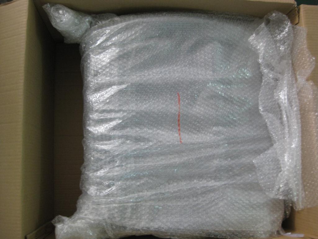
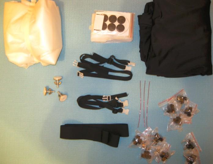
2 .Unpacking The telescope is packed in three shipping boxes, as described below. We recommend keeping the original packaging for the future usage. Make sure all the parts in the Parts List are present. Be sure to check all boxes carefully, as some parts are very small. If anything appears to be missing or broken, immediately Hubble Optics for assistance. Box #, The UL6 main structure Quantity Description Mirror Box/Rocker/Ground board Upper ring Spider Vanes Secondary spider hub and the diagonal secondary mirror holder Mirror Box, Rocker, and Ground Board Focuser L bracket (with 2 M5 x 6 screws) Secondary mirror Secondary Mirror Template Silicon RTV for gluing the secondary mirror 2" 0: dual speed focuser Plastic feet with wing nuts M6 knob screws (20mm long) with wingnuts for the truss tube and upper ring connection M6 knob screws for the truss tube and mirror box connection M6 knob screws for the ALT bearing assembly Magic nylon tape to hold the sling Brass wire to evenly separate cell support bars Nylon sling belt Center spot ring Mirror Cell Protection Pad 8 x 50 finder scope and bracket (option) Shroud (option) Truss Tube Carry Bag (option) 5-star artificial star (option) 2

3 Figure : Mirror Box/Rocker/Ground board 3


4 Figure 2:Upper Ring Figure 3: Spider Vanes 4


5 Figure 4:Secondary Spider Hub/Diagonal Support Figure 5: Focuser L Bracket 5

6 Figure 6: 4 Knob Screws 6

7 Box #2: The primary mirror Qty. Description Primary Mirror Box #3: Truss Tubes Qty. Description 8 Truss Tubes 7
, two 6-inch (50mm or smaller) adjustable crescent wrenches, and a scissor.")
8 2. Assembly Now that you have unpacked the boxes and familiarized yourself with all of the parts in front of you, it s time to begin assembly. You ll need a Regular screwdriver, a Phillips screwdriver, a set of metric hex keys (.5,2,2.5,3, 4, and 5mm), two 6-inch (50mm or smaller) adjustable crescent wrenches, and a scissor. Figure 7:Tools Required (Not provided) 2. Install the Secondary Mirror 2..Glue the Secondary to the diagonal holder First, remove the secondary mirror diagonal holder from the spider holder by loosening the center hex bolts using a hex key. Use a scissor to cut out the secondary mirror placement template as shown below. 8

.")
9 Figure 8:Secondary mirror placement template Place the mirror facing down on the wrapping paper used in the secondary mirror package or on a clean plastic zipper bag, and put the template on the back of the secondary mirror precisely along the edge of the mirror. Make sure that the mirror s back and diagonal holder head are clean prior to applying the supplied RTV. You should only use a fresh opened RTV (there is a catalytic component that evaporates with time). Evenly place 3 drops of small RTV blobs (about 0mm in diameter and 5mm thick), on the holder surface. 9
 on the back of the mirror, then place the diagonal holder with RTV blobs on the back of the")

10 Figure 9:Apply RTV to the Secondary Holder Place 3 coins (about.5 mm thick) on the back of the mirror, then place the diagonal holder with RTV blobs on the back of the secondary mirror. Make sure the secondary mirror holder is placed on the center of the secondary. The secondary holder should be concentric with all the circles on the template when viewed from the 45-degree angle. Figure 0:The secondary mirror is RTVed to the holder 0


11 Figure :The orientations of the secondary mirror and the holder should be precisely aligned

12 Figure 2:Viewed from the 45-degree angle Let the RTV cure for at least 24 hours at room temperature. Remove the coins and the template after the RTV cures. Please note that this procedure does not consider the offset of the secondary; which is neither necessary nor recommended. The offset will be fully factored in during the collimation procedure described in later section Assembly of the Secondary Cage Please note that most screws needed for the installation are already installed on the parts for easy identification. You do not need to have the scope completely setup to carry out this step of assembly. Attach the three spider wings to the spider holder Attach the three spider wings to the upper ring Attach the focuser L bracket to the upper ring and tighten the screws Attach the focuser to the L bracket and tighten the screws Attached the secondary holder with the secondary mirror (installed and cured) Roughly adjust the center bolt and the orientation of the secondary holder until the secondary mirror is centered by being viewed from the focuser draw tube Adjust and tighten the three collimation screws. 2


13 Figure 3:Attach the three spider wings to the spider hub Figure 4:Attach the three spider wings to the upper ring 3


14 Figure 5:Attach the focuser L bracket to the upper ring Figure 6:Attach the focuser to the L bracket 4


15 Figure 7:Attached the secondary holder with the secondary mirror Figure 8:Center the secondary in the focuser draw tube 5

16 2.2 Assembly of the Dobsonian Rocker The UL6 base is shipped assembled, the only thing you need to do is to install the three plastic feet. Make sure to use the wingnut to lock the three feet in their position. 2.3 Assembly of the Mirror Box The mirror box is very much assembled already; but you do need to install the primary mirror into the mirror box. Before install the primary mirror, you need perform the following tasks: Attach the 6 adhesive scratch protector to the three support bars Attach the three brass wires to regulate the support bars 6
.")

17 First bend the three brass wire to the following shape, with the center portion to be about 94 mm (a bit longer is OK, but all three should be the same length as much as possible). Insert the brass wires into the small holes on the support bars, and then bend the head portions to lock the brass wires in the position. Push the brass wires outward into a slight curve to keep the support bars staying in the position. 7

18 The primary mirror is shipped in its own box to prevent possible damage to the mirror. Once the primary mirror is installed in the mirror box, there will be no need to remove the mirror until cleaning is necessary. However, for shipping and the long time storage, the primary mirror should be packed tightly in its original package First, you will need to put the center spot on the mirror. Secure the mirror box to the Rocker with four supplied nylon strips Make sure the 3 support bars are evenly positioned Load the mirror into the cell 2.3. Center Spot The Primary Mirror. Place the wrapping paper used in the primary package flatly on a table. Place the primary mirror on the paper, facing down. Use a pencil to trace the circle around the mirror edge. 8


19 Then remove the mirror, and fold the paper along the traced line precisely to half circle, and then fold it again to make a quarter circle. Then cut out a small triangle shape at the tip of this quarter circle. You will see a small square hole was cut out at the center of the circle when unfolded. Make sure the size of the square is only slightly larger the then provided center mark ring. Then place the mirror on a table facing up, and place the holed paper on the mirror and center it, then put the center mark ring at the center of the mirror. 9

20 2.3.2 Install The Primary Mirror Unfold the two ALT bearings and use the M6 knob screw to tighten each top section in place. You may also want to tighten the pivot screw. 20


21 Figure 9:Tighten the knob screw and pivot screw Rotate the two eccentric side pins to make room for the primary mirror. Loosen the locknuts on the top of the mirror clips and turn them aside. Use a flat head screwdriver to open the split bolts, and insert the sling into the slot. Also loosen the nuts on the two split bolts that hold the sling. Stretch the sling loosely around the two lower side pins. Figure 20:Open the slot 2


22 Figure 2:Insert the sling Figure 22:Lock the mirror box to the rocker with nylon strips Make sure the mirror box is locked with the nylon strips to the rocker. Also make sure that the three mirror support bars are evenly placed in the cell. Pick up the mirror and place it into the mirror cell. Check that the mirror is centered and wiggles it a bit to insure that the cell parts are moving freely and adjusted to the float of the mirror. Next, place the sling in between the side pin and the side of the mirror. Rotate the two lower pin so there is between 3-6mm between the sling around the mirror and the side pins. 22

23 The side pins should not contact the mirror during observation. If the primary touches the pins, adjust the sling and or rotating the side pins that contacts it. Tighten the nuts that hold the side pins. The mirror protecting clips should not contact the mirror at all. Keep the clips about 3-6mm above the mirror surface. Place the mirror clips over the mirror and tighten the top lock nuts. At this point, the sling should be loosely around the mirror. On the lowest part of the mirror which will rest in the bottom of the sling, place a short piece of the provided magic nylon tape. Make sure the sling is in the middle of the mirror, so there is equal amount of glass above and below it. The magic tape will prevent the sling from slipping off the mirror when the telescope is pointed straight up. Now, leave the sling loose, you will adjust it after the telescope is fully assembled. Once the mirror is installed, you should use a square cardboard (not provided) to cover the mirror box up. 2.4 Install The Truss Tubes and Secondary Cage 2.4. Installation of the Truss Tubes The truss tube ends have an asymmetric shape, so they can be connected in opposite orientation as the following way to avoid the interference with each other. Make sure that the primary mirror is fully protected with a mirror box cover, which can be as simple as a square shape cardboard. Connect each two truss tubes with a M6 knob screw (20mm long one) and a M6 wing nut on the multiple hole side for the top end. The multiple holes are used for optimizing the OTA length for slight variation of focal length in the primary mirror. Normally, you should use the second hole from the top. Then connect each pair of the truss tubes to the mirror box with a M6 knob screw (4mm long) 23

24 Figure 23:Tighten the knob screws 24

25 2.4. Installation of the Secondary Mirror Cage Here is the installation procedure: Make sure that the primary mirror is fully protected with a mirror box cover, which can be as simple as a square shape cardboard. Loosen the wing nuts on all the knob screw as much as possible, but make sure they are still fully engaged on the bolts. Hold the secondary cage up and slide one of the slots on the upper ring into the top knob bolt of one truss pair. Make sure slide the slot into the space between wing nut and the truss tube ends. Then slide an adjacent slot into the knob bolt of the corresponding truss pair. Then slide the remaining two slots into the rest two knobs bolts at the same time Then tighten all knobs & wing nuts 25


26 Figure 24:Slide in one slot first 26

 split bolt. Just wrap one or two turns on this side.")
27 Figure 25:Then slide in one adjacent slot Figure 26:The slide in other two slots at the same time 2.5 Adjust the Sling After UL6 is fully assembled, the sling must be adjusted. The primary mirror must be supported in the sling and not by the side pins. Point UL6 about 5º above the horizon, an angle that can comfortably reach and adjust the collimation screws. You will need to use two wrenches to adjust the sling. Make sure that the Sling is hung through the slot on the left (or right) split bolt. Just wrap one or two turns on this side. To do this, rotate the head of the bolt with one wrench and hold the opposing nut with other wrench. Lock it tight. 27
28 Now go to the sling bolt on the other side. Hold the bolt head with one wrench and loosen the opposing nut. Turn the bolt to wrap the sling until the mirror is lift off the two lower pins. Raise the mirror until it almost touches the upper side pin. Lock the bolt in this position by tightening the lock nuts. Check to make sure that the mirror is indeed suspended on the sling by pushing on the back of the mirror with your fingertips. With UL6 in a nearly horizontal position, you should be able to move the mirror off the floatation cell support bars easily. If the mirror tilts against one of the side pins, loosen the retaining nuts and rotate that pin away from mirror until there is a few mm gap between the mirror and the pin. The mirror must be supported be the sling and not be the side pins. 3. Collimate the Optics. Keep the primary mirror covered during step. Point the telescope at 45 altitude during the collimation step -3. You need to make sure that the collimation will not shift when UL6 is pointed to different altitudes by tightening all locking nuts and screws properly along the entire optical path: The focuser is tightly locked in its square base The focuser square base is tightly locked onto the L focuser L bracket The focuser L bracket is tightly locked onto the upper ring All three spider vanes are tightly locked onto the spider hub and the upper ring The three collimation screws for the secondary mirror need to be properly tighten after the collimation All knob screws for all the truss tubes need to be tighten properly The three primary mirror lock screws need to be tighten properly Two positions have been provided to mount the focuser for the convenience. However, for the maximum collimation stability, and in particular for the heavy load, the focuser should be installed right on top the side Truss Tubes. Step : Center the secondary mirror on the axis of the focuser drawtube. Use a simple collimation cap (or sight tube) for this step. Insert the cap into the focuser, and look through the peephole of the sight tube at the secondary mirror. If you do not have collimation cap or sight tube, then simply eyeball it from a distance away from the center of drawtube. The secondary mirror should appear round and exactly centered in the sight tube. If is, then Step is done. If not, either the secondary holder or the focuser (or both) needs adjustment. 28
29 You should check and adjust the secondary holder first. If the error is up or down relative to the primary mirror, you can move it forward or away from the primary by adjusting the center bolt that connect the holder to the spider. If the error is toward either side of the focuser (90 to the optical axis), then check to find out if the secondary is well centered in the upper ring. If it isn't, adjust the spider's mounting screws until it is. If this checks out fine, then loosen the 3 mounting screws in the focuser bracket, then tilt the focuser as needed and tighten the mounting screws. Two of mounting holes on the bracket are slightly oversized to allow the focuser to be adjusted to a certain degree. You will have to remove the focuser to adjust the L bracket mounting screws. You may have to re-adjust the spider, if it is still not centered. Step 2: Here you adjust the tilt of the secondary mirror to aim the focuser's axis at the center of the primary. First, remove the primary mirror cover. A laser collimator will be used for this step: just center the laser beam on the primary's center spot by adjusting three secondary mirror collimation screws. A small error in secondary alignment is usually not a problem. As long as the pointing error is no more than or 2 percent of the main mirror's diameter, it makes no visible difference. You will need to repeat Step 2 each time you reassemble UL6. Step 3: In this, the final and most critical step, you need to tilt the main mirror to center its sweet spot (and its optical axis) in the focuser. This procedure should be done at the beginning of each observing session and checked occasionally during the night, since temperature changes or routine handling may cause your telescope's components to shift enough to change collimation. A laser collimator is used in this step. Just adjust the three primary collimation screws to center the laser s returning beam on the collimator s faceplate. 29


30 Figure 27:The primary mirror is not yet collimated. Figure 28:The primary mirror is collimated by laser collimator. 30
31 Step 4: Star-Testing Your Collimation You should always use an artificial star or a real star to verify the collimation of your scope. When collimating UL6 at horizontal position, you should mount the focuser at the position right on top of the truss tubes! UL6 is well engineered to hold the collimation across all position when the focuser is mounted at this position. First you should check if the scope is in rough collimation by observing a strongly defocused star image (move focuser in or out until seeing about 5-0 rings). Start this process with medium magnification eyepiece, but end up with a high magnification eyepiece. Center the star image at the center eyepiece. All rings and shadows should be concentric; if not, please perform the collimation by adjusting the three primary mirror collimation screws until all rings and shadows are concentric. If the scope is already in rough but not perfect collimation. You may find the location of the collimated field the part of the focal plane in your eyepiece where the outof-focus star is symmetric and adjust the primary mirror's collimation to bring the collimated field into the center of your eyepiece's field of view. You may repeat it a few times until the scope is in an excellent collimation. 4. Care and Maintenance 4. Mirror Storage UL6 should be stored in a clean, dry, dust-free place, safe from rapid changes in temperature and humidity. Do not store the telescope outdoors, your garage and shed might be OK, but is not recommended. We highly recommended storing the secondary cage, the mirror box with in our optional waterproof Nylon storage bag. Although big enough, make sure do not store the rocker/ground board with the 3
32 mirrors in the bag for long time; the potential evaporation from the lubricate material used by AZ bearing under high temperature will be harmful to the mirror coating. 4.2 Mirror Cleaning You should not have to clan the mirror often. The best thing you can do to your mirror is to keep it clean. A simple clean up using Optics Dust Air Dust Blower is the next best thing you can do. The following is how to clean a telescope mirror that is very dirty. Your new mirror should not be cleaned this way in any case. You ll need Clean towels Non-alkaline liquid detergent, such as Dreft, Basic H, Safe Suds - NO OTHERS. Skip step 2 if you cannot find the appropriate detergent. A bottle of distilled or de-ionized water A package of sterile cotton. Remove the primary mirror from the mirror box: Loosen the sling by loosening the lock nuts on the right split bolts with two wrenches. Carefully loosen the three retaining clips, and rotate all clips away from the mirror to clear the way for the mirror. Rotate the eccentric pins around to make as much room as possible for the mirror. To clean the secondary mirror, you will need to remove it from the telescope and clean it with the diagonal holder. Hold the secondary holder stationary while loosening the center Hex screw. You do not need to remove the secondary mirror from its RTVed holder when cleaning. Do not touch the surface of the mirror with your fingers. Lift it carefully by its edge. Step : Wash out the sink with detergent thoroughly, rinse it well with plenty of water, and lay a folded clean towel on the bottom. Take off any jewelry from your hands and wrists. Put the mirror (aluminized face up) on the towel, and with the drain open, play the mirror s surface with a gentle stream of room-temperature water for a few minutes. This will remove most dust and grit safely. Next, rinse the surface with a gentle stream of -distilled- water. Do not let the mirror dry. Step 2: Plug the sink, and fill the sink halfway with room temperature water. Add a few drops of the liquid detergent and let the mirror soak for 5 or 0 minutes. Then use a cotton ball, starting at one edge, swab the mirror in one direction, applying no pressure beyond the weight of the cotton itself. Grit is less abrasive wet than dry, so do this step under water if you can. Don't let the surface dry. 32
33 Turn the cotton over in a backward-rolling motion as you go, so that as soon as a part of it rubs the surface, that part is carried up and away from the glass. Throw out the cotton ball when it has been turned completely. Keep a very small stream of tap water flowing as you swab to rinse away detergent. Do not let the mirror surface dry or water marks will form. Keep the stream of tap water going. Drain the sink and run the room-temperature water over the mirror for a few minute. Step 3: Finally, rinse the mirror surface with distilled water. Hold the mirror nearly upright so the water runs off, leaving only small droplets behind. Your final rinse should be with distilled water. Repeat the process with the small secondary mirror. 5.Specification Optical design : Reflector Optical diameter : 406mm Focal length : 829mm Focal ratio : f/4.5 Optics type : Parabolic Eyepieces: Not included Optical quality : Diffraction limited++ (Strehl for the Primary, /0 lambada or for the secondary mirror) Finder scope : Not included Focuser : 2" dual-speed linear bearing Crayford Secondary mirror obstruction : 80 mm Secondary mirror obstruction by diameter : 9.7% Secondary mirror obstruction by area : 3.9% Mirror coatings/over-coatings : 92% Semi-Enhanced Aluminum coating on the primary and 96% Enhanced coating on the secondary mirror Materials : Aluminum Alloy (T6063-T6) tube with black stainless steel knob screws, T606-T6 Main structure, Structure Steel mirror cell Length of optical tube : 70.0 in. Weight, optical tube : 52.0 lbs. Weight, fully assembled : 60.0 lbs. Additional, optional accessories : 8x50 Finder, Shroud, Wheelbarrow, Vinyl foam Cushioned Grips Other features : Sling lateral support and deluxe push-pull brass knob collimation screws 33
Hubble Optics Ultra Portable UP 12 Dobsonian instruction manual
 Hubble Optics Ultra Portable UP 12 Dobsonian instruction manual Draft: 1.0 12-27-2016 Please read these instructions thoroughly before beginning assembly and subsequent use of the telescope. 1. Unpacking...2
Hubble GOTO Installation Instruction (1.3, 04/30/2014)
") Hubble GOTO Installation Instruction (1.3, 04/30/2014) 1. Preparation... 1 1.1 Tools required... 1 1.2 AZ GOTO Drive Parts List...1 1.3 ALT GOTO Drive Parts List... 1 2. The Azimuth motor drive installation...2
Hubble GOTO Installation Instruction (1.3, 04/30/2014) 1. Preparation... 1 1.1 Tools required... 1 1.2 AZ GOTO Drive Parts List...1 1.3 ALT GOTO Drive Parts List... 1 2. The Azimuth motor drive installation...2
SIPS instructions for installation and use
 SIPS instructions for installation and use Introduction Thank you for purchasing the Starlight Integrated Paracorr System (referred to as SIPS hereafter), which incorporates the best focuser on the market
USING THE 2 TELETUBE XLS TM & TELECAT XLS TM ADJUSTABLE SIGHT TUBE
 USING THE 2 TELETUBE XLS TM & TELECAT XLS TM ADJUSTABLE SIGHT TUBE Revised 09/20/08 With the rapid proliferation of larger-aperture, low f-ratio Newtonian telescopes with 2" focusers and larger diagonal
southpaw enterprises, inc.
 southpaw enterprises, inc. Instruction Sheet C-STAND 7100 Store these instructions in a safe place or with the enclosed maintenance checklist Take time to familiarize yourself with the use and maintenance
Frameless Inline Door With Return QCI5263
 INSTALLATION INSTRUCTIONS Frameless Inline Door With Return QCI5263 WALL MOUNT HINGES FRAMELESS DOOR / PANEL / RETURN PANEL QCI5263 REV. 0 Page 1 Certified 06/17/2016 Parts List with wall mount hinges
GlideRite Retractable Cover System For HotSpring & Tiger River Spas (except Classic & pre-2000 Landmark Spas)
") List of Contents Quantity Description 12 #10 x 1 ½ Flat Head Phillips Screw (see pg. 2) 2 #10 x ½ Pan Head Phillips Screw (see pg. 2) 8 ¼ x 2 ½ Lag Bolt (see pg. 2) 7 ¼ 20 x 5 / 8 Hex Head Bolt (see pg.
List of Contents Quantity Description 12 #10 x 1 ½ Flat Head Phillips Screw (see pg. 2) 2 #10 x ½ Pan Head Phillips Screw (see pg. 2) 8 ¼ x 2 ½ Lag Bolt (see pg. 2) 7 ¼ 20 x 5 / 8 Hex Head Bolt (see pg.
Hubble Optics CDK 17 Collimation Instructions 03/27/2012 Hubble Optics
 Hubble Optics CDK 17 Collimation Instructions 03/27/2012 Hubble Optics 1: CDK17 Specification: System Effective Focal Length: 2894.7 mm, (this might be slightly different for different set of optics) Figure
The Bowflex Revolution XP Home Gym Assembly Instructions. P/N: Rev ( /0 )
") P/N: 001-7057 Rev ( /0 ) The Bowflex Revolution XP Home Gym Assembly Instructions 2 Table of Contents Before You Start... 2 Tools You Will Need / Hardware Contents... 3 Box Contents... 6 Assembling Your
P/N: 001-7057 Rev ( /0 ) The Bowflex Revolution XP Home Gym Assembly Instructions 2 Table of Contents Before You Start... 2 Tools You Will Need / Hardware Contents... 3 Box Contents... 6 Assembling Your
Frameless Fixed Panel Slider
 INSTALLATION INSTRUCTIONS Frameless Fixed Panel Slider QCI-5279 SINGLE ROLLER WITH ANTI-JUMP DOUBLE ROLLERS QCI5279 Rev Page Certified 08/09/6 Tools: To install your New Shower Enclosure, you may need
UNIT No FRAMELESS PIVOT SHOWER DOOR
 INSTALLATION INSTRUCTIONS UNIT No. 3600 FRAMELESS PIVOT SHOWER DOOR NEED INSTALLATION HELP? Call 1-800-45-BASCO (452-2726) Monday - Friday 8:00 A.M. - 4:30 P.M. Eastern Time QCI0020 Rev. 3 Page 1 of 8
GlideRite Retractable Cover System For Hot Spot Spas (SE & SLX only)
") List of Contents Quantity Description 12 #10 x 1 ½ Flat Head Phillips Screw (see pg. 2) 2 #10 x ½ Pan Head Phillips Screw (see pg. 2) 8 ¼ x 2 ½ Lag Bolt (see pg. 2) 7 ¼ 20 x 5 / 8 Hex Head Bolt (see pg.
List of Contents Quantity Description 12 #10 x 1 ½ Flat Head Phillips Screw (see pg. 2) 2 #10 x ½ Pan Head Phillips Screw (see pg. 2) 8 ¼ x 2 ½ Lag Bolt (see pg. 2) 7 ¼ 20 x 5 / 8 Hex Head Bolt (see pg.
Unit No. 6150, 7150 Deluxe Framed Sliding Tub/Shower Enclosure
 INSTALLATION INSTRUCTIONS Unit No. 6150, 7150 Deluxe Framed Sliding Tub/Shower Enclosure QCI0023 Rev. 1 Page 1 of 8 Certified 8/20/10 MAINTENANCE: Two primary materials are used to manufacture your new
001-Component-build. Build the following Contraptor components before assembly:
 001-Component-build Build the following Contraptor components before assembly: http://www.contraptor.org/make-linear-rail-v2#assembly http://www.contraptor.org/make-linear-bearings-v2#assembly http://www.contraptor.org/make-sliding-elements#assembly
Frameless Bypass Slider
 INSTALLATION INSTRUCTIONS Frameless Bypass Slider QCI-5301 Heavy Glass Bypass Slider with Exposed Rollers QCI5301 Rev 0 Page 1 Certified 11/1/2016 Tools: To install your New Shower Enclosure, you may need
Nancy s Knit Knacks LLC 4 Yard Option Upgrade Kit Assembly Instructions and User Manual
 Nancy s Knit Knacks LLC 4 Yard Option Upgrade Kit Assembly Instructions and User Manual Thank you for purchasing our 4 Yard Option (4YO) Upgrade Kit. To install this upgrade you are simply going to assemble
Frameless Inline Door QCI5248
 INSTALLATION INSTRUCTIONS Frameless Inline Door QCI5248 FRAMELESS PANEL / DOOR / PANEL QCI5248 REV. 0 Page 1 Certified 06/16/2016 Parts List with glass to glass hinges *Quantities may vary. **Support Bar
Frameless Fixed Panel Slider QCI5279
 Frameless Fixed Panel Slider QCI5279 F AB GLASS AND MIRROR www.fabglassandmirror.com Call: +1 888-474-2221 Fax: (614)-334-4919 Office Timing: 8:30-18:00 EST info@fabglassandmirror.com Frameless Fixed Panel
INSTALLATION INSTRUCTIONS FRAMELESS CONTINUOUS HINGE SHOWER ENCLOSURE QCI5233
 INSTALLATION INSTRUCTIONS FRAMELESS CONTINUOUS HINGE SHOWER ENCLOSURE QCI5233 QCI5233 Rev 0 Page 1 Certified 06/20/2016 INSTALLATION NOTES: Unpack your unit carefully and inspect for freight damage. Lay
Cam Handle Service Guide
 Cam Handle Service Guide Page 2. Introduction Page 3. Troubleshooting guide Page 4-5. Adjusting the clamp force Page 6-7. Disassembling, greasing and replacing components Page 8-9. Replacing the post bearings
FRAMED SLIDING DOOR FOR TUB OR SHOWER ENCLOSURE 6150A-7150A
 FRAMED SLIDING DOOR FOR TUB OR SHOWER ENCLOSURE 6150A-7150A F AB GLASS AND MIRROR www.fabglassandmirror.com Call: +1 888-474-2221 Fax: (614)-334-4919 Office Timing: 8:30-18:00 EST info@fabglassandmirror.com
Astro-Physics Inc. 400QMD Lubrication/Maintenance Guide
 Astro-Physics Inc. 400QMD Lubrication/Maintenance Guide The following guidelines should be followed to lubricate the three main parts of the 400QMD mount. The QMD stands for Quartz Micro-Drive controller.
Frameless Inline Door QCI5254
 INSTALLATION INSTRUCTIONS Frameless Inline Door QCI5254 FRAMELESS DOOR / PANEL QCI5254 REV. 0 Page 1 Cer fied 06/16/2016 Parts List with wall mount hinges *Quanes may vary QCI5254 REV. 0 Page 2 Cer fied
Lumber Smith. Assembly Manual. If you are having problems assembling the saw and need assistance, please contact us at:
 Lumber Smith Assembly Manual If you are having problems assembling the saw and need assistance, please contact us at: 804-577-7398 info@lumbersmith.com 1 Step 1 Safety Carefully read the Owners Manual.
FRAMED SLIDING DOOR FOR TUB OR SHOWER ENCLOSURE INSTALLATION INSTRUCTIONS
 FRAMED SLIDING DOOR FOR OR SHOWER ENCLOSURE INSTALLATION INSTRUCTIONS QCI5023 REV. 0 Page 1 Certified 06/22/2016 INSTALLATION NOTES: Unpack your unit carefully and inspect for freight damage. Lay out and
Installation And Care Instructions. Vertical Honeycomb Shades
 Installation And Care Instructions Vertical Honeycomb Shades Rev 5/2013 Table Of Contents Getting Started... 3 Parts Overview... 4 Materials Required... 5 Tools Required... 6 Outside Mount Installation...
RAMPAGE P R O D U C T S. INSTALLATION INSTRUCTIONS BRONCO ZIPPER FASTRACK TOP PART #984xx BRONCO TOOLS REQUIRED
 RAMPAGE P R O D U C T S 84 (+/- 1/4 ) INSTALLATION INSTRUCTIONS BRONCO ZIPPER FASTRACK TOP PART #984xx BRONCO 1966-1977 TOOLS REQUIRED 3/8 WRENCH 7/16 WRENCH ½ WRENCH #2 PHILLIPS SCREWDRIVER 1/8 DRILL
INSTALLATION AND CARE INSTRUCTIONS
 INSTALLATION AND CARE INSTRUCTIONS Vertical Applications Honeycomb Shades 52 C8-10-3401 Rev 2/14 CONTENTS Introduction...2 Before You Begin...3 Vertical Application Parts Overview...4 Materials Required...5
INSTALLATION INSTRUCTIONS FRAMELESS CONTINUOUS HINGE SHOWER ENCLOSURE QCI5232
 INSTALLATION INSTRUCTIONS FRAMELESS CONTINUOUS HINGE SHOWER ENCLOSURE QCI5232 QCI5232 Rev 0 Page 1 Certified 06/20/2016 INSTALLATION NOTES: Unpack your unit carefully and inspect for freight damage. Lay
PFT CABLE GYM INSTRUCTION MANUAL
 PFT CABLE GYM INSTRUCTION MANUAL QUESTION? As a quality home gym supplier we are committed to your complete satisfaction. If you have questions, or find missing or damaged parts, we will guarantee your
CV1B Sliding Table Installation and Setup Guide
 CV1B Sliding Table Installation and Setup Guide Tech Mark, Inc 7901 Industry Drive North Little Rock, AR 72117 tel (501) 945-9393 fax (501) 945-0312 www.tech-mark.com email: info@tech-mark.com The CV1B
3/8 FRAMELESS BYPASS SLIDING SHOWER ENCLOSURE
 INSTALLATION INSTRUCTIONS 3/8 FRAMELESS BYPASS SLIDING SHOWER ENCLOSURE QCI-5017 QCI5017 Rev. 3 Page 1 of 9 Certified 12/6/17 INSTALLATION NOTES: Unpack your unit carefully and inspect for freight damage.
Frameless Inline Door QCI5250
 INSTALLATION INSTRUCTIONS Frameless Inline Door QCI5250 FRAMELESS PANEL / DOOR / PANEL QCI0249 REV. 3 Page 1 Certified 10/12/12 Parts List with pivot hinges *Quantities may vary. QCI0249 REV. 3 Page 2
tile redi redi DOOR Redi Redi Swing Slide g TM TM...Opening Doors to Stunning Showers! TM TM SERIES: CONFIGURATION: MOUNTING PACKAGE:
 redi DOOR INSTALLATION INSTRUCTIONS tile redi Redi Redi Swing Slide g TM TM...Opening Doors to Stunning Showers! TM TM SERIES: CONFIGURATION: MOUNTING PACKAGE: 1100 Door-Door Framed sliding doors RDQCI5023
Frameless Bypass Slider
 INSTALLATION INSTRUCTIONS Frameless Bypass Slider QCI-5301 3/8 or 1/4 Glass Bypass Slider with Exposed Rollers QCI5301 Rev 1 Page 1 Certified 6/5/2017 Tools: To install your New Shower Enclosure, you may
Howie's Laser Collimator Instructions:
 Howie's Laser Collimator Instructions: WARNING: AVOID DIRECT OR MIRROR REFLECTED EYE EXPOSURE TO LASER BEAM The laser collimator is a tool that enables precise adjustment of the alignment of telescope
935 RODA VINESSE NEED INSTALLATION HELP? DOUBLE ROLLERS FRAMELESS DOOR INSTALLATION INSTRUCTIONS QCI XX/XX/XXXX. Call BASCO ( )
") INSTALLATION INSTRUCTIONS 935 RODA DOUBLE ROLLERS FRAMELESS DOOR NEED INSTALLATION HELP? Call 1-800-45-BASCO (452-2726) Monday - Friday VINESSE QCI0286 1 XX/XX/XXXX 935 Roda Parts List With double rollers
INSTALLATION INSTRUCTIONS 935 RODA DOUBLE ROLLERS FRAMELESS DOOR NEED INSTALLATION HELP? Call 1-800-45-BASCO (452-2726) Monday - Friday VINESSE QCI0286 1 XX/XX/XXXX 935 Roda Parts List With double rollers
INSTALLATION INSTRUCTIONS. UNIT No. 160/760 THIN-LINE SHOWER ENCLOSURE
 INSTALLATION INSTRUCTIONS UNIT No. 160/760 THIN-LINE SHOWER ENCLOSURE QCI0011 Rev. 0 Page 1of 10 Certified 10/18/2006 MAINTENANCE: Two primary materials are used to manufacture your new Basco enclosure;
The Astronomical League
 The Astronomical League www.astroleague.org Library Telescope Modifications Check the collimation with the eyepiece cap provided (the one with the hole in its center) before starting on any modifications.
tile redi redi DOOR Redi Redi Swing Slide g TM TM...Opening Doors to Stunning Showers! TM TM SERIES: CONFIGURATION: MOUNTING PACKAGE:
 redi DOOR INSTALLATION INSTRUCTIONS tile redi Redi Redi Swing Slide g TM TM...Opening Doors to Stunning Showers! TM TM SERIES: CONFIGURATION: MOUNTING PACKAGE: 3000 Door-Door Header, sliding doors RDQCI5301
FRAMED PANEL / DOOR / PANEL CONTINUOUS HINGE SHOWER ENCLOSURE INSTALLATION INSTRUCTIONS
 FRAMED / DOOR / CONTINUOUS HINGE SHOWER ENCLOSURE INSTALLATION INSTRUCTIONS QCI5229 Rev 0 6 INSTALLATION NOTES: Unpack your unit carefully and inspect for freight damage. Lay out and identify all parts
C L A S S I C. Deluxe. Snow Thrower Cab. Assembly and Care Instructions
 C L A S S I C Deluxe Snow Thrower Cab Assembly and Care Instructions Deluxe Snow Thrower Cab Assembly and Care Instructions Before you begin please unpack the carton and check that you have all your parts.
Installation and Assembly - Universal Articulating Swivel Double-Arm for 42" - 60" Plasma Screens
 Installation and Assembly - Universal Articulating Swivel Double-Arm for 42" - 60" Plasma Screens Models: PLAV 70-UNL, PLAV 70-UNL-S PLAV 70-UNLP, PLAV 70-UNLP-S R This product is UL Listed. It must be
1/4 FRAMELESS DOOR WITH INLINE PANEL 1413A-1713A-1813A
 1/4 FRAMELESS DOOR WITH INLINE PANEL 1413A-1713A-1813A F AB GLASS AND MIRROR www.fabglassandmirror.com Call: +1 888-474-2221 Fax: (614)-334-4919 Office Timing: 8:30-18:00 EST info@fabglassandmirror.com
FRAMELESS DOOR / PANEL WITH WALL MOUNT HINGES QCI5274
 FRAMELESS DOOR / PANEL WITH WALL MOUNT HINGES QCI5274 QCI0274 QCI5274 REV. Rev. 1 0 Page Page 1 1 Date Certified: Certified 06/16/2016 10/01/10 Parts List with wall mount hinges ITEM NO. Part # DESCRIPTION
Installation and Assembly - Universal Articulating Swivel Double-Arm for 42" - 60" Plasma Screens
 Installation and Assembly - Universal Articulating Swivel Double-Arm for 42" - 60" Plasma Screens Models: PLAV 70-UNL, PLAV 70-UNL-S PLAV 70-UNLP, PLAV 70-UNLP-S R This product is UL Listed. It must be
BABY WOLF LOOM. Assembly Instructions for Knocked-Down Looms
 BABY WOLF LOOM Assembly Instructions for Knocked-Down Looms BEFORE YOU BEGIN Please read through the directions before beginning to assemble your loom. Unpack the loom parts carefully. Do not throw away
Deluxe Continuous Hinge Framed Door & Inline Panel with Return Panel Shower Enclosure
 INSTALLATION INSTRUCTIONS Deluxe Continuous Hinge Framed Door & Inline Panel with Return Panel Shower Enclosure QCI0235 Page 1 of 11 Certified 08/20/10 MAINTENANCE: Two primary materials are used to manufacture
400A 40113V, 401A 40120V, & 401AL 40120VL ALUMINUM VERTICAL 4000 LB LIFT INCLUDES SCREW LEG ASSEMBLY INSTRUCTIONS
 12/11/07 PAGE 1 OF 12 400A 40113V, 401A 40120V, & 401AL 40120VL ALUMINUM VERTICAL 4000 LB LIFT INCLUDES SCREW LEG ASSEMBLY INSTRUCTIONS Thank you for purchasing our product! *Please read these instructions
INSTALLATION INSTRUCTIONS 960 RODA GLASS TO GLASS HINGES ANGLED FRAMELESS PANEL / DOOR / PANEL CELESTA DRESDEN TRESOR
 INSTALLATION INSTRUCTIONS 960 RODA GLASS TO GLASS HINGES NEED INSTALLATION HELP? Call 1-800-45-BASCO (452-2726) Monday - Friday 8:00 A.M. - 4:30 P.M. Eastern Time ANGLED FRAMELESS PANEL / DOOR / PANEL
INSTALLATION INSTRUCTIONS
 INSTALLATION INSTRUCTIONS BUILDERS CHOICE FRAMED Bypass Door Model: L0516 (Tub Height), L0517 (Shower Height) Rev. 09.20.13 INSTALLATION NOTES: Unpack your unit carefully and inspect for freight damage.
Electric Skein Winder
 Electric Skein Winder Assembly and Use Package Contents 1 - Triangular Body (w/ motor) 1 - Cross Arm 1 - Left Foot (w/ yarn guide) 1 - Right Foot 1 - Adjustable Finger (w/ yarn clip) 3 - Adjustable Fingers
WARNING: Wear safety goggles at all times when the engine is running and cooling
 WARNING: Wear safety goggles at all times when the engine is running and cooling Please be safe and enjoy your engine. It is not a child's toy it is a precision machined working model. Never leave Children
ASSEMBLY INSTRUCTIONS FOR YOUR 5510s STATIONARY CRIB
 THIS CRIB CONFORMS TO APPLICABLE REGULATIONS PROMULGATED BY THE CONSUMER PRODUCT SAFETY COMMISION AND BY THE AMERICAN SOCIETY FOR TESTING AND MATERIALS ASSEMBLY INSTRUCTIONS FOR YOUR 10s STATIONARY CRIB
ASSEMBLING YOUR L&L EASY-FIRE KILN
 TABLE OF CONTENTS TOOLS NEED FOR THE JOB............ 1 UNPACKING........................... 2 Inspect for visible damage.......................... 2 Remove Top from Carton........................... 2
INSTALLATION AND CARE INSTRUCTIONS
 INSTALLATION AND CARE INSTRUCTIONS Vertical Applications Honeycomb Shades CONTENTS Introduction...2 Before You Begin...3 Vertical Application Parts Overview...4 Materials Required...5 Tools Required...6
Removing and Replacing the Y-truck
 Service Documentation Removing and Replacing the Y-truck To remove and replace the Y-truck you will need the following tools: 4mm Allen wrench 12mm stamped flat wrench #2 Phillips screwdriver (magnetic
INSTALLATION GUIDE 2009-CURRENT HUMMER H3T PRODUCT CODE:
 INSTALLATION GUIDE 2009-CURRENT HUMMER H3T PRODUCT CODE: 268 June 22, 2010 TOOLS NEEDED COMPONENTS INCLUDED P2 Tip 3/8" Drill Rubber Gasket(s) x 2 Bracket(s) x 2 1/2" Drill Bit Bulkhead Flange #2 Phillips
Unit No. 135, 735 Deluxe Pivot Inline Door & Panel Shower Enclosure
 INSTALLATION INSTRUCTIONS Unit No. 135, 735 Deluxe Pivot Inline Door & Panel Shower Enclosure NEED INSTALLATION HELP? Call 1-800-45-BASCO (452-2726) Monday - Friday 8:00 A.M. - 4:30 P.M. Eastern Time QCI0004
MantelMount. TM1A Installation Instructions IMPORTANT SAFETY INSTRUCTIONS - SAVE THESE INSTRUCTIONS
 MantelMount TMA Installation Instructions IMPORTANT SAFETY INSTRUCTIONS - SAVE THESE INSTRUCTIONS TM Thank you for choosing the MantelMount television wall mount. Please read this entire manual before
ABM International, Inc. Navigator Assembly Manual
 ABM International, Inc. 1 1.0: Parts List Tablet (Qty. 1) Tablet mount (Qty. 1) NOTE: Mount may appear and operate different then image below Control Box (Qty. 1) Motor Power Supply (Qty. 1) 2 X-axis motor
METAL BLINDS. Deluxe GETTING STARTED OPTIONAL HARDWARE. A few simple tools are required: STANDARD HARDWARE
 METAL BLINDS Deluxe GETTING STARTED OPTIONAL HARDWARE A few simple tools are required: Steel Tape Measure Pencil Level Hold Down Brackets with Screws Extension Bracket Power Drill and Drill Bits Flathead
RAMPAGE P R O D U C T S. BRONCO ZIPPER FASTRACK TOP PART #984xx BRONCO TOOLS REQUIRED
 RAMPAGE P R O D U C T S 84 (+/- 1/4 ) BRONCO ZIPPER FASTRACK TOP PART #984xx BRONCO 1966-1977 TOOLS REQUIRED 3/8 WRENCH 7/16 WRENCH ½ WRENCH #2 PHILLIPS SCREWDRIVER 1/8 DRILL BIT 9/64 DRILL BIT 5/32 DRILL
KD Table Base Assembly and Top Attachment Instructions
 KD Table Base Assembly and Top Attachment Instructions 4011xx 5000xx 7014xx 8001xx 8206xx Congratulations on the purchase of your Tropitone furniture. Read through all steps before starting assembly. CAUTION:
Before beginning refer to page 4 to assure that all parts are included in your kit. Refer to diagrams for help when installing top and hardware.
 INSTALLATION INSTRUCTIONS BRONCO 1980-1994 PART #98501 RAMPAGE P R O D U C T S Thank you for purchasing Rampage Products Top for your Bronco. Please read and follow, precisely, all installation instructions
INSTALLATION INSTRUCTIONS 935 RODA GLASS TO GLASS HINGES FRAMELESS DOOR / PANEL CELESTA DRESDEN GEOLUX TRESOR VONSE
 INSTALLATION INSTRUCTIONS 935 RODA GLASS TO GLASS HINGES NEED INSTALLATION HELP? Call 1-800-45-BASCO (452-2726) Monday - Friday 8:00 A.M. - 4:30 P.M. Eastern Time FRAMELESS DOOR / PANEL CELESTA DRESDEN
1/4 FRAMELESS CONTINUOUS HINGE SHOWER ENCLOSURE 1400A-1700A-1800A
 1/4 FRAMELESS CONTINUOUS HINGE SHOWER ENCLOSURE 1400A-1700A-1800A F AB GLASS AND MIRROR www.fabglassandmirror.com Call: +1 888-474-2221 Fax: (614)-334-4919 Office Timing: 8:30-18:00 EST info@fabglassandmirror.com
O W N E R ' S M A N U A L
 TABLE TENNIS TABLE MODEL NOS. T861 T861B O W N E R ' S M A N U A L 1. Read this manual carefully before starting assembly. Read each step completely before beginning each step.. Some smaller parts may
LifeGear G1 /HOME GYM ITEM NO.: 63100
 LifeGear G1 /HOME GYM ITEM NO.: 63100 OWNER S MANUAL IMPORTANT: Read all instructions carefully before using this product. Retain this owner s manual for future reference. The specifications of this product
Frameless Heavy Glass Door with Wall Mount Hinges
 INSTALLATION INSTRUCTIONS Frameless Heavy Glass Door with Wall Mount Hinges QCI-5245 QCI5245 REV. 0 Page 1 Certified 06/16/16 Frameless Door with Wall Mount Hinges ITEM NUMBER DESCRIPTION QUANTITY 1 DOOR
Frameless Inline Door QCI5288
 Frameless Inline Door QCI5288 QCI5288 Rev. 0 Page 1 Date Certified: 06/21/2016 Tools: To install your New Shower Enclosure, you may need the following: Pencil Drill Hack Saw Low Tack Tape 1/8 & 3/16 Drill
WOLF PUP LOOM TM & WOLF PUP LT LOOM TM
 WOLF PUP LOOM TM & WOLF PUP LT LOOM TM Assembly Instructions FL3000 FL3006 FL3009 WOLF PUP WOLF PUP LT Find out more at schachtspindle.com Schacht Spindle Company 6101 Ben Place Boulder, CO 80301 p. 303.442.3212
Star Trac Turbo Trainer Assembly & Setup
 Star Trac Turbo Trainer Use the following procedures to unpack and assemble your Turbo Trainer manufactured by Star Trac. UNPACKING AND PARTS LIST Position the shipping carton so the Heavy End logo is
FINGER JOINT TEMPLATES LEIGH DEDICATED CUSTOMER SUPPORT Using the F3, F18 and F24 Finger Joint Templates on Leigh D-Series & SuperJigs
 LEIGH FINGER JOINT TEMPLATES Using the F, F and F Finger Joint Templates on Leigh D-Series & SuperJigs DEDICATED CUSTOMER SUPPORT -00-- ii Introduction F, F & F FINGER JOINT TEMPLATES USERGUIDE FOREWORD
Assembly Instructions for Laser Sailboat Dolly (with Beach Wheels for 1 Axle & Ramp Wheels with Reversible Axle)
") Assembly Instructions for Laser Sailboat Dolly (with Beach Wheels for 1 Axle & Ramp Wheels with Reversible Axle)! IMPORTANT: Before you begin, please read these instructions and check to be sure that all
Assembly Instructions for Laser Sailboat Dolly (with Beach Wheels for 1 Axle & Ramp Wheels with Reversible Axle)! IMPORTANT: Before you begin, please read these instructions and check to be sure that all
Two Panel Frameless Bypass Door
 INSTALLATION INSTRUCTIONS Two Frameless Bypass Door Series 00 Please Record Model Number From Carton Label Here Please read these instructions carefully to familiarize yourself with the required tools,
QCI0029 REV. 1 Page 1 of 11 Certified 07/06/05
 QCI0029 REV. 1 Page 1 of 11 Certified 07/06/05 MAINTENANCE: Two primary materials are used to manufacture your new Basco enclosure: tempered glass and anodized aluminum. To assure a long lasting finish
Warnings. Description. Prior to Installation Tools Needed
 Warnings Failure to act in accordance with the following may result in death or personal injury. The JT Strong Arm Stabilizer System is intended to eliminate chassis movement in travel trailers and fifth
INSTALLATION INSTRUCTIONS
 INSTALLATION INSTRUCTIONS BRONCO FAST TRAC TOP PART #331-210 BRONCO 1966-1977 Thank you for purchasing Specialty s Convertible Top for your Bronco. It has been designed for great fit and long wear. Please
1/4 FRAMELESS CONTINUOUS HINGE SHOWER ENCLOSURE
 1/4 FRAMELESS CONTINUOUS HINGE SHOWER ENCLOSURE QCI5028 Rev 1 Page 1 Certified 09/19/2018 INSTALLATION NOTES: Unpack your unit carefully and inspect for freight damage. Lay out and identify all parts using
SE5a Instrument Board part 2 - rev 1.1
 SE5a Instrument Board part 2 - rev 1.1 Fuel (Petrol) Valve This valve uses two circular name plates, eight brass screws, one black plastic base, copper wire and two black plastic risers. You can pick any
FIXED SHOWER SCREEN For Wall Mount Hinges QCI5283
 FIXED SHOWER SCREEN For Wall Mount Hinges QCI5283 QCI5283 Page 1 Date Certified: 06/16/2016 Parts List with wall mount clamp ITEM NO. DESCRIPTION QTY. 1 FIXED GLASS PANEL 1 2 WALL MOUNT CLAMP 1 3 U-CHANNEL
1503 Follow Spot Yoke, Source Four LED
 1503 Follow Spot Yoke, Source Four LED Rev 1.0 2016 City Theatrical, Inc. Getting Started with the City Theatrical Follow Spot Yoke for source four LED Congratulations on the purchase of your City Theatrical
Repairing Microsoft Wedge Touch Mouse Battery Cover Retaining Clip
 Repairing Microsoft Wedge Touch Mouse Battery Cover Retaining Clip Disassembly, repair and reassembly of Wedge Touch mouse when the battery cover will not stay closed. Also is a good guide to repair other
Sales & Service. JFK - Just For Kids. sasportonline.com. 135 Forestview Road 7879 Will Rogers Blvd.
 Sales & Service sasportonline.com SA Sport (Canada) SA Sport (U.S.A.) 135 Forestview Road 7879 Will Rogers Blvd. P.O. Box 40 Fort Worth, Texas Orillia, Ontario USA 76140 Canada L3V 6H9 Telephone: (705)
Unit No. 4400, 4500 Classic Frameless Sliding Tub/Shower Enclosure INSTALLATION INSTRUCTIONS
 Unit No. 4400, 4500 Classic Frameless Sliding Tub/Shower Enclosure INSTALLATION INSTRUCTIONS MAINTENANCE: Two primary materials are used to manufacture your new Basco enclosure: tempered glass and anodized
Hip Roof Canopy Instructions
 Hip Roof Canopy Instructions - PUT SAFETY FIRST. NOT COMPLYING WITH THE PROCEDURES AND PRECAUTIONS OUTLINED IN THIS MANUAL MAY RESULT IN PERSONAL INJURY AND WILL INVALIDATE THE WARRANTY.. Before attempting
Steele TV Stand Stock # BH
 LOT NUMBER: DATE PURCHASED: / / Steele TV Stand Stock # BH46-084-899-02 ADULT ASSEMBLY REQUIRED If you have any questions regarding assembly or if parts are missing, DO NOT return this item to the store
southpaw enterprises, inc.
 southpaw enterprises, inc. Store these instructions with the enclosed maintenance checklist in a safe place. You may also access them on our website. Instruction Sheet Wood Joist 2-1/2 Ft. Drop Ceiling
LEG CURL IP-S1315 INSTALLATION INSTRUCTIONS
 LEG CURL IP-S35 INSTALLATION INSTRUCTIONS Copyright 2009. Star Trac by Unisen, Inc. All rights reserved, including those to reproduce this book or parts thereof in any form without first obtaining written
Operator s Manual. Onion King 500N 501N 502N 503N ENGLISH
 Onion King 500N 501N 502N 503N Thank you for purchasing this Vollrath Food Processing Equipment. Before operating the equipment, read and familiarize yourself with the following operating and safety instructions.
PORTA~TRACE. GAGNE, INC. 41 Commercial Dr. Johnson City, New York Phone: Fax: ASSEMBLY INSTRUCTIONS
 PORTA~TRACE GAGNE, INC. 41 Commercial Dr. Johnson City, New York 13790 Phone: 1-607-729-3366 Fax: 1-607-729-7644 ASSEMBLY INSTRUCTIONS PORTA~TRACE MODEL 2436T LIGHT TABLE PORTA~TRACE MODEL 3648T LIGHT
Frameless Door QCI5284
 Frameless Door QCI5284 F AB GLASS AND MIRROR www.fabglassandmirror.com Call: +1 888-474-2221 Fax: (614)-334-4919 Office Timing: 8:30-18:00 EST info@fabglassandmirror.com INSTALLATION INSTRUCTIONS Frameless
PEDAL TIMPANI. TP3300 series TP3323 / TP3326 / TP3329 / TP3332. Owner s Manual
 PEDAL TIMPANI TP3300 series TP3323 / TP3326 / TP3329 / TP3332 Owner s Manual English Thank you for purchasing Yamaha Timpani. Please read through this manual carefully as it contains important information
AG Optical Systems. Newtonian Astrograph Manual Version AG Optical Systems
 AG Optical Systems Newtonian Astrograph Manual Version 2 2012 Table of Contents 1. Introduction 2. System Specifications 3. Initial Assembly 4. Collimation 5. Care and Cleaning 6. Cooling Fan Operation
ESSENCE. Shower / Tub Door Installaion Instructions
 ESSENCE Shower / Tub Door Installaion Instructions IMPORTANT DreamLine reserves the right to alter, modify or redesign products at any time without prior notice. For the latest up-to-date technical drawings,
Gared Pro-S Portable Backstop
 Models: 9616 & 9618 Installation, Operation and Maintenance Instructions Please read all instructions before attempting installation or operation of these units SAVE THESE INSTRUCTIONS FOR FUTURE USE PUBLICATION
Serial Number Location
 GL/GLX STRENGTH TRAINING SYSTEM OWNERS MANUAL Serial Number Location SERIAL 3 4 5 7 8 Record your Serial number and purchase date here: S/N DATE: DEALER: Model No. BCG-GL BODYCRAFT is a division of Recreation
Series 1100 Aluminum Door Canopy
 Series 00 Aluminum Door Canopy with Support Arms It is our recommendation that you read instructions carefully prior to assembly and installation. Series 00 with Support Arms MOUNTING BAR (A) TOP TRIM
High Density Sports Storage
 Owner s Manual High Density Sports Storage CONTENTS Safety...........................................2 General......................................2 Installation...................................2 Usage.......................................2