FireWire Vision Tools
|
|
|
- Shon Dennis
- 5 years ago
- Views:
Transcription

1 A simple MATLAB interface for FireWire cameras 100 Select object to be tracked F. Wörnle, January 2008
2 1
3 Contents 1. Introduction Installation The FireWire Vision Tools interface Supported video modes Image capture commands capimage acqimage Image processing commands capproc capclassify imgproc Selecting colour ranges Simulink interface Simple stereoscopic vision...34 Appendix A The camera configuration file Appendix B Recompiling the drivers
4 1. Introduction This document describes a small collection of MATLAB commands through which access is provided to digital cameras on the 1394 FireWire bus. Most of these commands are to be issued from the MATLAB command line but there also is an S-Function block which gives access to the camera from within a Simulink model. Some of the commands of the toolbox include rudimentary image processing capabilities. It is possible to classify image content based on a programmable colour specification. For each detected object, the image processing algorithm returns the coordinates of the centroid as well as the coordinates of a boundary box around the object. Groups of objects sharing the same colour specification can be merged at different degrees, thereby allowing the granularity of the object detection system to be adjusted as required by the application. The toolbox aims at providing an easy to use interface for student projects, laboratory experiments and any application with a need for simple machine vision, e. g. camera based robotics applications such as RoboCup, etc. In addition, a number of commands are based on the assumption that there are two cameras sharing a 1394 bus. This feature can be used in projects in which stereoscopic vision is required. All stereoscopic commands include the label Stereo as part of their command name. The toolbox should work well with most FireWire cameras. It is based on a universal driver for FireWire cameras: CMU 1394 Digital Camera Driver (version 6.4.4, developed at the Robotics Institute of Carnegie Mellon University ( Please note that tests have exclusively been run with a Unibrain fire-i camera ( so it cannot be granted that other FireWire cameras will work although this is highly likely, as both the CMU driver and the commands of the toolbox are fairly generic. A variety of video modes are supported (YUV444, YUV422, YUV411, RGB8, Y8, Y16). Image dimensions can be defined freely from a minimum of 1 x 2 pixels up to the full size of a frame as specified by the selected mode (160 x 120 for YUV444, 320 x 240 for YUV422 and 640 x 480 for all other modes). Support of resolutions higher than 640 x 480 can easily be incorporated. However, this requires a few simple changes in the source code and recompilation. The classification algorithms are those of the Color Machine Vision project (CMVision), a project conducted by the CORAL group at the Carnegie Mellon School of Computer Science ( This software has been published under the GNU General Public License (GPL) and can be obtained from (CMVision project page). CMVision provides a simple, robust vision system suitable for real time 3
5 robotics applications by means of global low level colour vision at video rates without the use of special purpose hardware. To install the FireWire Vision Tools toolbox, extract the contents of the archive to a local folder. The _bin folder of the distribution should then be added to the MATLAB search path. The CMU 1394 Digital Camera Driver can be obtained from the above source. For convenience, the driver has also been included in the folder _CMU_Driver_v644. Refer to section 2 for details of how to install this driver. Please note that this driver might have to be installed for each camera to be used with the toolbox (see section 2). The FireWire Vision Tools are distributed as Free Software under the terms of the GNU General Public License Agreement. Users are therefore given the right to copy, re-distribute and/or modify the source code to suit their needs. The present release of this toolbox has been developed and tested using MATLAB R2007a. Comments and bug reports are always welcome. Please direct your feedback to: Frank Wornle January,

6 2. Installation The CMU 1394 Digital Camera Driver can be installed from the folder _CMU_Driver_v644 included in this distribution of the FireWire_VisionTools toolbox. Connect the camera and open the System Properties from the Control Panel of Windows start menu. Select the Hardware tab and open the Device Manager. There should be an entry called Imaging Devices under which your camera will appear with its current name and driver settings. 5


7 Double-click on the name of your camera to open its Properties control window and select the Driver tab. 6
. Close the Driver details window and click on Update Driver.")
8 You can display the Driver Details to find out which driver is currently installed for this camera (e.g. the generic Windows driver sonydcam.sys). Close the Driver details window and click on Update Driver. This will launch the Hardware Update Wizard. 7


9 Choose No, not this time to prevent Windows from being overly eager in wasting your time. Click Next. On the next page choose Install from a list or specific location (Advanced) and click Next. 8

10 Select option Don t search. I will choose the driver to install and click Next. Windows might list a number of compatible drivers it knows of, but that is of no importance at this stage. Click on Have Disk.... Click on Browse and find the folder _CMU_Driver_v644 included in the distribution of this toolbox. 9


11 This folder should include the installation file 1394Camera.inf. 10


12 Click on Open and then click on Ok. Windows will get all nervous and tell you that This driver is not digitally signed! which, as usual, can be ignored. Click on Next. More waffle about the Microsoft Logo testing... click on Continue Anyway. 11
 gets copied to the Windows system32/drivers folder")

13 Now the actual driver file (1394cmdr.sys) gets copied to the Windows system32/drivers folder and the corresponding registry entries are set. This concludes the installation of the CMU 1394 Digital Camera Device driver. 12

14 The successful installation can be checked using Driver Details button. 13

15 Once the driver has been installed, the toolbox is ready to be used. If not already done, add the _bin folder of the distribution to the MATLAB search path. Each toolbox command comes with a simple test program, usually called test. Change to the folder of a particular command, e.g. acqimage and start the m-script test. Note that these scripts have been implemented as MATLAB functions, i. e. they can be called with call-up parameters: To start the script with all parameters at their default values simply type >> test To test camera mode 1 (YUV422, 320 x 240) type >> test(1) To test the camera in mode 2 (YUV411, 640 x 480 the default mode) while reducing the image size to 100 x 100 with the origin at (20, 50) type etc. >> test(2, 100, 100, 20, 50) 14

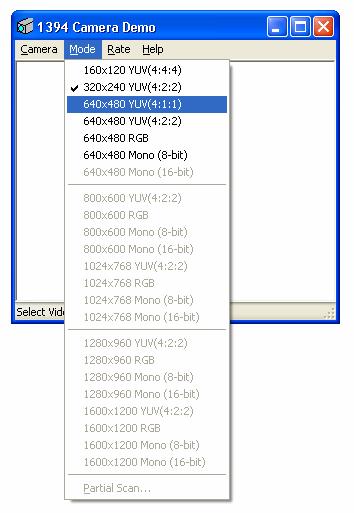
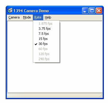
16 The available modes of a particular camera can be checked with the 1394 Camera Demo, which has also been included in this distribution (folder _CMU_Driver_v644). This small application can also be used to ensure the CMU driver has been installed properly for a particular camera (note: for some camera types the driver will have to be installed with each particular camera to be used with the system for instance the Unibrain fire-i camera). Check the link to the camera (menu: Camera). If a camera has been connected and is working properly the following message should be displayed: For stereoscopic vision two cameras need to be set up. Checking the link to the cameras will now indicated that two cameras have been found on the bus: 15

 to match the capabilities of a camera which is")
17 Each of these cameras has its own unique identifier this is the reason why the driver has to be installed twice Once a camera has been selected and initialized, its features can be displayed using this application. For each mode, the maximum possible frame rate can be found this way. This is useful, if a toolbox command needs to be modified (and then recompiled) to match the capabilities of a camera which is not fully supported by the toolbox yet. However, for most cameras, this will not be required. 16
18 17
19 3. The FireWire Vision Tools interface 3.1 Supported video modes Many FireWire cameras can be configured to produce digitized image information in a multitude of formats. The following video modes are supported by the commands of the FireWire Vision Tools toolbox: - YUV444 Each pixel is represented by 3 bytes, namely the luminance (Y), and two bytes of colour information: C r (= U) and C b (= V). The camera stores these byte triplets in the following order U-Y-V. - YUV422 Adjacent pairs of pixels are represented by 4 bytes, namely two individual luminance bytes (Y 1, Y 2 ), and two shared colour information bytes (U, V). The camera stores these bytes in the following order U-Y 1 -V-Y 2. - YUV411 Groups of 4 (adjacent) pixels are represented by 6 bytes, with four individual luminance bytes (Y 1 Y 4 ), and two shared colour information bytes (U, V). The order of bytes is as follows: U-Y 1 -Y 2 -V-Y 3 -Y 4. - RGB8 Each pixel is represented by a colour triplet of three consecutive bytes: Red, Green, Blue. - Y8 Only the luminance information is transmitted on the bus, with each pixel represented by one byte. - Y16 Only the luminance information is transmitted on the bus. Each pixel is represented by two bytes. The frame size and rate of an acquired image depends on the chosen video mode as well as a second format parameter. This parameter can take the values 0, 1 or 2, with frame sizes generally getting larger for larger values of format. Currently, the commands of the toolbox are configured for a fixed format of 0. This means that the frame sizes and rates are fixed as follows: YUV x120, 30 fps *) YUV x240, 30 fps YUV x480, 30 fps YUV x480, 15 fps RGB8 640x480, 15 fps Y8 640x480, 30 fps Y16 640x480, 15 fps *) fps = frames per second 18
20 Note: (1) The CMVision colour detection algorithms work in the YUV422 colour space (= YUYV or UYVY). All commands which rely on CMVision therefore have to convert the acquired image data to this format and, if the image is returned to MATLAB, a second conversion to the output format (RGB8) is needed. On the other hand, YUV411 data consumes less bandwidth on the FireWire bus than YUV422 data and/or RGB8 data. The choice of the video mode should take into account these two constraints (conversion effort, bus bandwidth). (2) For more details about image data formats and conversion routines to other formats see astronomy.swin.edu.au/~pbourke/dataformats/yuv. 3.2 Image capture commands This section describes commands which can be used from the MATLAB command line and/or m-scripts to acquire visual information and return it to the workspace in form of a cell array capimage This command acquires a single frame from the camera. The call-up syntax is as follows: >> capimage??? Usage: data = capimage(mode [, verbose][, sizex, sizey][, originx, originy]) mode: -1 STOP 0 YUV444 (160x120, 30 fps) 1 YUV422 (320x240, 30 fps) 2 YUV411 (640x480, 30 fps) 3 YUV422 (640x480, 15 fps) 4 RGB8 (640x480, 15 fps) 5 Y8 (640x480, 30 fps) 6 Y16 (640x480, 15 fps) verbose: 0 silent 1 verbose Like all commands of the toolbox, capimage requires specification of the video mode (0 6). In addition to this compulsory call-up parameter, there are up to 5 optional parameters: a verbose flag, the size of the section of the acquired frame to be returned as well as the origin of this section within the frame. Setting verbose to 1 causes the camera settings to be written to the MATLAB command window. This can be useful when the exact features of a particular FireWire camera are not known, e.g.: 19
21 >> image(capimage(2,1)) Adjusting camera settings... Programming camera '1' with: done. Number of cameras found: 1 Device description (node 0): unibrain fire-i_1.2 ( ) Camera name: Fire-i 1.2 Vendor name: Unibrain Version number: 256 Max speed: 400 Link status 0 Has power control: 1 Status power control: 0 Has 1394b: 0 Status 1394b: 0 Number of channels (camera): 0 Current channel (camera): 0 Camera supports video mode: 160X120 YUV 4:4:4 [24 bits per pixel] Camera supports video mode: 320X240 YUV 4:2:2 [16 bits per pixel] Camera supports video mode: 640X480 YUV 4:1:1 [12 bits per pixel] Camera supports video mode: 640X480 YUV 4:2:2 [16 bits per pixel] Camera supports video mode: 640X480 RGB (8-bit) [24 bits per pixel] Camera supports video mode: 640X480 Mono (8-bit) [8 bits per pixel] Unsupported video mode: 640X480 Mono (16-bit) Feature 'Brightness' (ID 0) Range (min, max): 128, 383 Current value: 304 Attribute 'AutoMode': 0 Feature 'Auto Exposure' (ID 1) Range (min, max): 0, 511 Current value: 511 Attribute 'AutoMode': 0 Feature 'Sharpness' (ID 2) Range (min, max): 0, 255 Current value: 80 Feature 'White Balance' (ID 3) Range (min, max): 0, 255 Current values (low, high): 96, 69 Attribute 'AutoMode': 0 Feature 'Saturation' (ID 5) Range (min, max): 0, 255 Current value: 90 Feature 'Shutter' (ID 7) Range (min, max): 0, 7 Current value: 6 Feature 'Gain' (ID 8) Range (min, max): 0, 255 Current value: 187 The displayed status information reveals for example that, on the fire-i camera, there is no 16-bit black-and-white video mode (Y16). Piping the output of the capimage command through to the image command of MATLAB is an easy way to display the acquired image. Alternatively, the image data can be assigned to a MATLAB workspace variable. Independent of the chosen video mode, the output format is always an n x n x 3 cell array containing the corresponding Red, Green and Blue values. 20

22 The following lines cause MATLAB to continuously acquire YUV411 images, convert them to RGB and display them on screen. The program stops after 100 frames. Upon completion of 100 cycles, image capturing is stopped by calling the driver with call-up parameter -1. % start camera, YUV411 mode for(i=1:100) image(capimage(2)); drawnow end % stop camera capimage(-1); Note: Fixed camera settings are expected to be defined in a text file called cameraconfig.txt. This file should be located in the folder the capturing command is called from. If cameraconfig.txt cannot be found, the camera is switched back to automatic mode. 21
23 The following six hardware attributes of the camera can be set in cameraconfig.txt. The specified values are examples which gave good results in our laboratory at the University of Adelaide (indoors environment, bright): Shutter speed: 6 Saturation level: 90 White balance: 96, 69 (fixed automatic adjustment switched off) Gain: 87 Auto exposure: 511 (fixed automatic adjustment switched off) Brightness: 304 (fixed automatic adjustment switched off) acqimage This command does much the same as capimage (section 3.2.1). However, internally images are taken from a constant stream of images. This may (or may not) result in a slightly better performance. Note that, as for all other commands, the size of the image to be returned can be reduced. This may be useful, when the horizontal position of an object is to be determined (e.g. far left, left, centre, right, far right). In this case, it might be much quicker to just process a reduce part of the captured image possibly just a few lines and/or columns. In particular, it might be much more efficient to detect an object (e.g. a mobile robot on the floor) in an initially fully sized frame and then home in on the detected object for tracking. This way, the bulk of the image processing is done on a much smaller number of pixels than what would be the case when processing a full sized frame. Every time the robot reaches the limits of the reduced area, its origin is adjusted by a small x and y to re-adjust the relative position of the robot to the centre of the processing frame. This approach should lead to a much improved overall performance of the image processing system. MODE: RGB8 (640x480, 15 fps) -- Close figure window to exit (e.g. ALT+F4)
. 3.3.1 capproc This command can be used to detect and track objects. A number of CMVision algorithms are used to classify the acquired image data.")
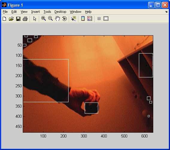
24 3.3 Image processing commands The commands presented in this section combine image acquisition (e.g. capimage) with the data classification algorithms of the CMVision project (see: The CORAL group, www-2.cs.cmu.edu/~jbruce/cmvision/) capproc This command can be used to detect and track objects. A number of CMVision algorithms are used to classify the acquired image data. Clusters with the requested size and/or colour qualities are being detected and made available to MATLAB in form of a cluster information structure. This structure includes, among other things, the position and size of a rectangular box around the cluster as well as the coordinates of its centroid. The location of the centroid can directly be used in tracking applications Detecting 3 different colours - Cluster boundary box and cluster centroid The above example demonstrates the situation for a relatively selective colour specification, i. e. with rather narrow ranges in each category Y, U, V. A boundary box has been superimposed with the captured image to reveal the 23
25 size of the detected cluster. The small star denotes the location of the centroid. The admissible colour ranges are communicated to the image processing engine by means of a colour definition file (e.g. color.txt ). This text file can include colour attributes for up to 32 different objects to be detected. The general structure of the colour file is shown below: [Colors] (255,128, 0) Ball (255,255, 0) Yellow_Team ( 0, 0,255) Blue_Team (255,255,255) White (255, 0,255) Marker_Pink (160, 0,160) Marker_Purple ( 0,160, 0) Marker_Green ( 0, 0, 0) C08 ( 0, 0, 0) C09 ( 0, 0, 0) C10 ( 0, 0, 0) C11 ( 0, 0, 0) C12 ( 0, 0, 0) C13 ( 0, 0, 0) C14 ( 0, 0, 0) C15 ( 0, 0, 0) C16 (255,128, 0) Ball_2 (255,255, 0) Yellow_Team_2 ( 0, 0,255) Blue_Team_2 (255,255,255) White_2 (255, 0,255) Marker_Pink_2 (160, 0,160) Marker_Purple_2 ( 0,160, 0) Marker_Green_2 [Thresholds] ( 7:175, 50:150,160:200) ( 47:120, 5:80, 130:200) ( 76:112,110:190, 67:128) (130:255, 81:131,125:178) ( 50:181,102:135,190:222) (103: 96,118:140,144:166) ( 67:134, 96:129, 85:124) ( 0: 0, 0: 0, 0: 0) ( 0: 0, 0: 0, 0: 0) ( 0: 0, 0: 0, 0: 0) ( 0: 0, 0: 0, 0: 0) ( 0: 0, 0: 0, 0: 0) ( 0: 0, 0: 0, 0: 0) ( 0: 0, 0: 0, 0: 0) ( 0: 0, 0: 0, 0: 0) ( 0: 0, 0: 0, 0: 0) ( 0: 0, 0: 0, 0: 0) ( 86:221, 35: 79,102:150) ( 0: 0, 0: 0, 0: 0) ( 0: 0, 0: 0, 0: 0) ( 0: 0, 0: 0, 0: 0) ( 0: 0, 0: 0, 0: 0) ( 0: 0, 0: 0, 0: 0) 24
![Section [Colors] includes four columns: (1) A user defined RGB colour triplet which can be used to visualize the pixels of a detected cluster.](/docs-images/80/81754556/images/26-0.jpg "This can be useful to validate the settings of a particular colour detection range. An example with four different detected regions is shown below.")
26 Section [Colors] includes four columns: (1) A user defined RGB colour triplet which can be used to visualize the pixels of a detected cluster. This can be useful to validate the settings of a particular colour detection range. An example with four different detected regions is shown below Setting all pixels of a detected cluster to its default colour (2) The merge density parameter is assigned a value between 0 and 1. It it is a measure for the degree of object merging which takes place upon colour detection. A value near 1 results in many separate small objects (very little merging between the individual clusters of a particular colour). Decreasing the merge density parameter allows for an increasing amount of merging to take place, thereby resulting in fewer but bigger objects. This parameter thus controls the granularity of detected clusters within an acquired image. (3) Colour ID; this parameter can be used to identify clusters of a particular colour quality. (4) Colour name; this optional name can be used to link a detected object to a clear text identifier. Section [Thresholds] contains the RGB colour ranges which are used to detect a particular cluster. 25
27 For further details about the CMVision algorithms, please refer to the CMVision manuals (www-2.cs.cmu.edu/~jbruce/cmvision/). For example, the following colour specification was used to produce the output shown below [Colors] (0, 255, 0) green [Thresholds] (12:24, 124:128, 125:133) % black ball, living room, night On the other hand, setting the merge density parameter to 0.95 produces a much more fine granular result: [Colors] (0, 255, 0) green [Thresholds] (20:32, 121:125, 130:138) % black ball, living room, night 26
![capproc can be invoked with the following call-up parameters: [Region_StructureArray [,RGB_Data]] = capproc( mode [, 'colour_filename'] [, colour_list] [, verbose] [, sizex, sizey] [, originx,](/docs-images/80/81754556/images/28-0.jpg "originy] ) As with capimage, the only required parameter is the video mode. If the (optional) colour_filename has not been specified, the default name testcolours.txt is used.")
28 capproc can be invoked with the following call-up parameters: [Region_StructureArray [,RGB_Data]] = capproc( mode [, 'colour_filename'] [, colour_list] [, verbose] [, sizex, sizey] [, originx, originy] ) As with capimage, the only required parameter is the video mode. If the (optional) colour_filename has not been specified, the default name testcolours.txt is used. In addition to these call-up parameters, a verbose flag, the size of the image to be processed (and optionally returned) as well as the origin of this subsection within the entire frame can be specified. capproc always returns the result of the image processing step (clusters, centroids, colours, names,...). Additionally, the corresponding image data can be returned in an optional 2 nd output parameter (RGB). 27
. 220 200 180 160 140 120 100 80 60 40 20 50 100 150 200 3.")
29 3.3.2 capclassify The command capclassify can be used to find appropriate settings for a particular parameter in the colour file. All pixels of a detected cluster are set to their default colour (1 st column in section [Colors]) imgproc The command imgproc can be used to test the validity of a chosen colour definition. This command takes a previously stored RGB image as input and processes it using CMVision. Optionally, the colour filename and/or a vector of colour IDs can be specified. The command returns a list of all detected regions together with their size, co-ordinates of the centroid, etc. See the test program in folder imgproc for further details. 28

30 3.4 Selecting colour ranges Object tracking by colour detection relies on the correct definition of appropriate RGB (or YUV) colour ranges. Too wide a range will lead to an unwanted detection of objects with similar colour qualities; on the other hand, too narrow ranges might cause the algorithm to return without having detected anything. To determine appropriate RGB ranges, a number of MATLAB m-file scripts have been provided. These training programs allow a user to select an object to be tracked from either a still image (trainstill.m) or a live stream of images (traincamera.m). Both programs return the colour characteristics of the selected object. The thus established values (ranges of Y, U, V) can directly be copied to a colour definition file. Additional information on the issue of colour training can be found in the document Train_UserManual.doc which has been included in the present distribution of the toolbox. Training the camera to see the ball 29
 of the first detected object of each specified colour is provided as an output signal of the block.")
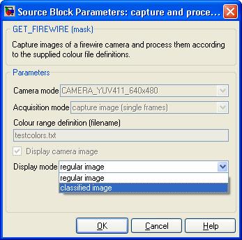
31 3.5 Simulink interface The toolbox also provides an S-Function to allow objects to be tracked from within a Simulink model (see the example in folder SFcapProc). The most recent image captured by the camera is processed and the centroid coordinates (x, y) of the first detected object of each specified colour is provided as an output signal of the block. The block mask allows specification of the video mode to be used (e.g. YUV411), the acquisition mode (single frames or stream based) as well as the name of the colour definition file. Optionally, the captured image as well as centroid information and boundary boxes can be displayed ( display check box). When the display is enabled, the display format of the image can be chosen to be a regular image or a classified image (see below). 30
32 SFCapProc: Displaying a regular image 31

33 SFCapProc: Displaying a classified image 32


34 Classify mode: Detected objects are coloured, undetected objects are black Regular display mode: Detected objects have centroids and boundary boxes 33

35 3.6 Simple stereoscopic vision Two or more UniBrain fire-i cameras can be daisy-chained to transmit images on the same firewire bus interface. This can be used to provide a simple MATLAB interface for experiments with stereoscopic vision. The command capimagestereo assumes that two cameras have been connected to the same bus interface. The following command sequence illustrates how two images can be captured by capimagestereo or captured and processed by capprocstereo (uses a common colour definition file) or capprocstereo2 (uses two separate colour definition files). Note that all cameras are usually slightly different in the figure below, the brightness property of camera 1 is larger (187) than that of camera 2 (87). The camera settings can be adjusted iteratively until one and the same colour detection specification works equally well with both cameras. Alternatively, capprocstereo2 could be used: [out1, out2, im1, im2] = capprocstereo2(2, 'c1.txt', 'c2.txt'); subplot(1,2,1) image(im1); title('first camera'); axis image; drawnow subplot(1,2,2) image(im2); title('second camera'); axis image; drawnow A simple stereoscopic vision system Note that UniBrain fire-i cameras do not provide for synchronized sampling. Therefore, strictly speaking, this is not stereoscopic vision. However, if the objects to be tracked are not moving too fast, this method is an easy way to experiment with stereoscopic vision systems. More information about synchronized image acquisition using FireWire cameras can be found the following document: ools/firewire_and_iidc_cameras.pdf 34
36 Appendices 35
37 Appendix A The camera configuration file The camera configuration file (cameraconfig.txt) has the structure shown below. The [Format] section outlines the meaning of the entries for each camera. This structure is fixed and should not be modified (the driver files simply ignore this section). The entries in sections [Camera_1] and [Camera_2] define the parameters listed in the format section (in that order). The default values have been found using the configuration panel of the demo program that comes with the driver (1394CameraDemo). The values work in our indoor environment, but any slight change in the lighting conditions may require a re-adjustment. [Format] Shutter (6) Saturation (90) White Balance (96 69) Gain (87) Auto Exposure (511) Brightness (304) [Camera_1] [Camera_2]
38 Appendix B Recompiling the drivers The file structure of this toolbox includes a development folder (_devlpmt). Within this folder, each of the commands has its own subfolder. To recompile any of the commands, change directory to the corresponding subfolder, e.g. >> cd _devlpmt/capproc edit the source file as required and then recompile using the provided script cc : >> cc Once compiled, copy the newly created mex32 file (e.g. capproc.mex32) to the _bin folder of the toolbox. Subsequent calls to capproc() will now make use of the modified command. 37
TIS Vision Tools A simple MATLAB interface to the The Imaging Source (TIS) FireWire cameras (DFK 31F03)
 FireWire cameras (DFK 31F03)") A simple MATLAB interface to the The Imaging Source (TIS) FireWire cameras (DFK 31F03) 100 Select object to be tracked... 90 80 70 60 50 40 30 20 10 20 40 60 80 100 F. Wörnle, Aprit 2005 1 Contents 1 Introduction
A simple MATLAB interface to the The Imaging Source (TIS) FireWire cameras (DFK 31F03) 100 Select object to be tracked... 90 80 70 60 50 40 30 20 10 20 40 60 80 100 F. Wörnle, Aprit 2005 1 Contents 1 Introduction
A simple MATLAB interface to FireWire cameras. How to define the colour ranges used for the detection of coloured objects
 How to define the colour ranges used for the detection of coloured objects The colour detection algorithms scan every frame for pixels of a particular quality. A coloured object is defined by a set of
How to define the colour ranges for an automatic detection of coloured objects
 How to define the colour ranges for an automatic detection of coloured objects The colour detection algorithms scan every frame for pixels of a particular quality. To recognize a pixel as part of a valid
SCD-0017 Firegrab Documentation
 SCD-0017 Firegrab Documentation Release XI Tordivel AS January 04, 2017 Contents 1 User Guide 3 2 Fire-I Camera Properties 9 3 Raw Color Mode 13 4 Examples 15 5 Release notes 17 i ii SCD-0017 Firegrab
Stratigraphy Modeling Boreholes and Cross Sections
 GMS TUTORIALS Stratigraphy Modeling Boreholes and Cross Sections The Borehole module of GMS can be used to visualize boreholes created from drilling logs. Also three-dimensional cross sections between
Batch Counting of Foci
 Batch Counting of Foci Getting results from Z stacks of images. 1. First it is necessary to determine suitable CHARM parameters to be used for batch counting. First drag a stack of images taken with the
Operating Instructions Pocket Pictor For use with Pocket Pc s
 Introduction Operating Instructions Pocket Pictor For use with Pocket Pc s The compact size and low power consumption of Pocket PC s make them ideal for use in the field. Pocket Pictor is designed for
1 ImageBrowser Software User Guide 5.1
 1 ImageBrowser Software User Guide 5.1 Table of Contents (1/2) Chapter 1 What is ImageBrowser? Chapter 2 What Can ImageBrowser Do?... 5 Guide to the ImageBrowser Windows... 6 Downloading and Printing Images
inphoto ID Canon camera control software Automatic ID photography User Guide
 inphoto ID Canon camera control software Automatic ID photography User Guide 2008 Akond company 197342, Russia, St.-Petersburg, Serdobolskaya, 65A Phone/fax: +7(812)600-6918 Cell: +7(921)757-8319 e-mail:
Matlab for CS6320 Beginners
 Matlab for CS6320 Beginners Basics: Starting Matlab o CADE Lab remote access o Student version on your own computer Change the Current Folder to the directory where your programs, images, etc. will be
inphoto ID Canon and Olympus camera control software Automatic ID photography User Guide
 inphoto ID Canon and Olympus camera control software Automatic ID photography User Guide 2006 Akond company 197342, Russia, St.-Petersburg, Serdobolskaya, 65a Phone/fax: +7(812)600-6918 Cell: +7(921)757-8319
Stitching MetroPro Application
 OMP-0375F Stitching MetroPro Application Stitch.app This booklet is a quick reference; it assumes that you are familiar with MetroPro and the instrument. Information on MetroPro is provided in Getting
ToupSky Cameras Quick-guide
 ToupSky Cameras Quick-guide ToupSky is a capture and processing software offered by Touptek, the original manufacturer of the Toupcamera series. These are video cameras that offer live image capture for
MY ASTROPHOTOGRAPHY WORKFLOW Scott J. Davis June 21, 2012
 Table of Contents Image Acquisition Types 2 Image Acquisition Exposure 3 Image Acquisition Some Extra Notes 4 Stacking Setup 5 Stacking 7 Preparing for Post Processing 8 Preparing your Photoshop File 9
ThermaViz. Operating Manual. The Innovative Two-Wavelength Imaging Pyrometer
 ThermaViz The Innovative Two-Wavelength Imaging Pyrometer Operating Manual The integration of advanced optical diagnostics and intelligent materials processing for temperature measurement and process control.
Introduction to Simulink Assignment Companion Document
 Introduction to Simulink Assignment Companion Document Implementing a DSB-SC AM Modulator in Simulink The purpose of this exercise is to explore SIMULINK by implementing a DSB-SC AM modulator. DSB-SC AM
Photoshop CS2. Step by Step Instructions Using Layers. Adobe. About Layers:
 About Layers: Layers allow you to work on one element of an image without disturbing the others. Think of layers as sheets of acetate stacked one on top of the other. You can see through transparent areas
ECE411 - Laboratory Exercise #1
 ECE411 - Laboratory Exercise #1 Introduction to Matlab/Simulink This laboratory exercise is intended to provide a tutorial introduction to Matlab/Simulink. Simulink is a Matlab toolbox for analysis/simulation
Locating Molecules Using GSD Technology Project Folders: Organization of Experiment Files...1
 .....................................1 1 Project Folders: Organization of Experiment Files.................................1 2 Steps........................................................................2
Stratigraphy Modeling Boreholes and Cross. Become familiar with boreholes and borehole cross sections in GMS
 v. 10.3 GMS 10.3 Tutorial Stratigraphy Modeling Boreholes and Cross Sections Become familiar with boreholes and borehole cross sections in GMS Objectives Learn how to import borehole data, construct a
ISCapture User Guide. advanced CCD imaging. Opticstar
 advanced CCD imaging Opticstar I We always check the accuracy of the information in our promotional material. However, due to the continuous process of product development and improvement it is possible
USER GUIDE. NEED HELP? Call us on +44 (0)
") USER GUIDE NEED HELP? Call us on +44 (0) 121 250 3642 TABLE OF CONTENTS Document Control and Authority...3 User Guide...4 Create SPN Project...5 Open SPN Project...6 Save SPN Project...6 Evidence Page...7
USER GUIDE NEED HELP? Call us on +44 (0) 121 250 3642 TABLE OF CONTENTS Document Control and Authority...3 User Guide...4 Create SPN Project...5 Open SPN Project...6 Save SPN Project...6 Evidence Page...7
Software Guide for Windows ZoomBrowser EX PhotoStitch
 Software Guide for Windows ZoomBrowser EX PhotoStitch Special Features Transfer Images and Movies Insert Text ABC Save Still Images From Movies Edit Movies A Print Images Back Up to a CD Attach Images
Document history Date Doc version Ifx version Editor Change
 Document history Date Doc version Ifx version Editor Change Jan 2008 2 5.21.0300 HV Nov 2015 2.1 5.60.0400 JW Update for 5.60.0400 Inclusion of Epiphan Image Capture Nov 2017 2.2 5.70.0100 JW Update for
TeliU3vViewer. User s Guide Ver.1.0.0
 TeliU3vViewer User s Guide Ver.1.0.0 Please refer the latest instruction manual as contents are subject to change without notice for improvement Table of Contents 1. About This Document... 4 2. System
inphoto ID SLR Automatic ID photography With Canon SLR camera User Guide
 inphoto ID SLR Automatic ID photography With Canon SLR camera User Guide 2014 Akond company Phone/fax: +7(812)384-6430 Cell: +7(921)757-8319 e-mail: info@akond.net akondsales@gmail.com http://www.akond.net
We recommend downloading the latest core installer for our software from our website. This can be found at:
 Dusk Getting Started Installing the Software We recommend downloading the latest core installer for our software from our website. This can be found at: https://www.atik-cameras.com/downloads/ Locate and
Applying mathematics to digital image processing using a spreadsheet
 Jeff Waldock Applying mathematics to digital image processing using a spreadsheet Jeff Waldock Department of Engineering and Mathematics Sheffield Hallam University j.waldock@shu.ac.uk Introduction When
inphoto ID PS Automatic ID photography With Canon PowerShot camera User Guide
 inphoto ID PS Automatic ID photography With Canon PowerShot camera User Guide 2018 Akond company Phone/fax: +7(812)384-6430 Cell: +7(921)757-8319 e-mail: info@akond.net akondsales@gmail.com http://www.akond.net
CHAPTER1: QUICK START...3 CAMERA INSTALLATION... 3 SOFTWARE AND DRIVER INSTALLATION... 3 START TCAPTURE...4 TCAPTURE PARAMETER SETTINGS... 5 CHAPTER2:
 Image acquisition, managing and processing software TCapture Instruction Manual Key to the Instruction Manual TC is shortened name used for TCapture. Help Refer to [Help] >> [About TCapture] menu for software
CONTENTS. Chapter I Introduction Package Includes Appearance System Requirements... 1
 User Manual CONTENTS Chapter I Introduction... 1 1.1 Package Includes... 1 1.2 Appearance... 1 1.3 System Requirements... 1 1.4 Main Functions and Features... 2 Chapter II System Installation... 3 2.1
4.5.1 Mirroring Gain/Offset Registers GPIO CMV Snapshot Control... 14
 Thank you for choosing the MityCAM-C8000 from Critical Link. The MityCAM-C8000 MityViewer Quick Start Guide will guide you through the software installation process and the steps to acquire your first
Wound Analyzer TiVi103 User Manual. User Manual 1.1 Version 1.1 October 2012 PIONEERS IN TISSUE VIABILITY IMAGING
 Wound Analyzer TiVi103 User Manual User Manual 1.1 Version 1.1 October 2012 PIONEERS IN TISSUE VIABILITY IMAGING Dear Valued Customer! Welcome to the WheelsBridge TiVi103 Wound Analyzer system intended
Hartmann Sensor Manual
 Hartmann Sensor Manual 2021 Girard Blvd. Suite 150 Albuquerque, NM 87106 (505) 245-9970 x184 www.aos-llc.com 1 Table of Contents 1 Introduction... 3 1.1 Device Operation... 3 1.2 Limitations of Hartmann
Image Processing Tutorial Basic Concepts
 Image Processing Tutorial Basic Concepts CCDWare Publishing http://www.ccdware.com 2005 CCDWare Publishing Table of Contents Introduction... 3 Starting CCDStack... 4 Creating Calibration Frames... 5 Create
ID Photo Processor. Batch photo processing. User Guide
 ID Photo Processor Batch photo processing User Guide 2015 Akond company 197342, Russia, St.-Petersburg, Serdobolskaya, 65a Phone/fax: +7(812)384-6430 Cell: +7(921)757-8319 e-mail: info@akond.net http://www.akond.net
MCD Viewer 1.0 USER GUIDE
 PN 400317 MCD Viewer 1.0 USER GUIDE For Research Use Only. Not for use in diagnostic procedures. Information in this publication is subject to change without notice. It is Fluidigm policy to improve products
Unsupervised Classification
 Unsupervised Classification Using SAGA Tutorial ID: IGET_RS_007 This tutorial has been developed by BVIEER as part of the IGET web portal intended to provide easy access to geospatial education. This tutorial
Surface Analyzer TiVi95 User Manual. User Manual 3.1 Version 3.1 January 2012 PIONEERS IN TISSUE VIABILITY IMAGING
 Surface Analyzer TiVi95 User Manual User Manual 3.1 Version 3.1 January 2012 PIONEERS IN TISSUE VIABILITY IMAGING Dear Valued Customer! Welcome to the WheelsBridge TiVi95 Skin Surface Analyzer system intended
Introduction to Simulation of Verilog Designs Using ModelSim Graphical Waveform Editor. 1 Introduction. For Quartus II 13.1
 Introduction to Simulation of Verilog Designs Using ModelSim Graphical Waveform Editor For Quartus II 13.1 1 Introduction This tutorial provides an introduction to simulation of logic circuits using the
Digital Image Processing. Lecture # 6 Corner Detection & Color Processing
 Digital Image Processing Lecture # 6 Corner Detection & Color Processing 1 Corners Corners (interest points) Unlike edges, corners (patches of pixels surrounding the corner) do not necessarily correspond
Princeton ELE 201, Spring 2014 Laboratory No. 2 Shazam
 Princeton ELE 201, Spring 2014 Laboratory No. 2 Shazam 1 Background In this lab we will begin to code a Shazam-like program to identify a short clip of music using a database of songs. The basic procedure
NIRSpec Technical Note NTN Author(s): S. Birkmann Date of Issue: September 27, 2012 Version: 1.2
: S. Birkmann Date of Issue: September 27, 2012 Version: 1.2") NIRSpec Technical Note NTN-2012-002 Author(s): S. Birkmann Date of Issue: September 27, 2012 Version: 1.2 estec European Space Research and Technology Centre Keplerlaan 1 2201 AZ Noordwijk The Netherlands
NIRSpec Technical Note NTN-2012-002 Author(s): S. Birkmann Date of Issue: September 27, 2012 Version: 1.2 estec European Space Research and Technology Centre Keplerlaan 1 2201 AZ Noordwijk The Netherlands
Version 2 Image Clarification Tool for Avid Editing Systems. Part of the dtective suite of forensic video analysis tools from Ocean Systems
 By Version 2 Image Clarification Tool for Avid Editing Systems Part of the dtective suite of forensic video analysis tools from Ocean Systems User Guide www.oceansystems.com www.dtectivesystem.com Page
House Design Tutorial
 Chapter 2: House Design Tutorial This House Design Tutorial shows you how to get started on a design project. The tutorials that follow continue with the same plan. When you are finished, you will have
Brightness and Contrast Control Reference Guide
 innovation Series Scanners Brightness and Contrast Control Reference Guide A-61506 Part No. 9E3722 CAT No. 137 0337 Using the Brightness and Contrast Control This Reference Guide provides information and
FTA SI-640 High Speed Camera Installation and Use
 FTA SI-640 High Speed Camera Installation and Use Last updated November 14, 2005 Installation The required drivers are included with the standard Fta32 Video distribution, so no separate folders exist
Stratix II Filtering Lab
 October 2004, ver. 1.0 Application Note 362 Introduction The filtering reference design provided in the DSP Development Kit, Stratix II Edition, shows you how to use the Altera DSP Builder for system design,
Picture Style Editor Ver Instruction Manual
 ENGLISH Picture Style File Creating Software Picture Style Editor Ver. 1.18 Instruction Manual Content of this Instruction Manual PSE stands for Picture Style Editor. In this manual, the windows used in
Instruction Manual for HyperScan Spectrometer
 August 2006 Version 1.1 Table of Contents Section Page 1 Hardware... 1 2 Mounting Procedure... 2 3 CCD Alignment... 6 4 Software... 7 5 Wiring Diagram... 19 1 HARDWARE While it is not necessary to have
Motion Detection Keyvan Yaghmayi
 Motion Detection Keyvan Yaghmayi The goal of this project is to write a software that detects moving objects. The idea, which is used in security cameras, is basically the process of comparing sequential
i800 Series Scanners Image Processing Guide User s Guide A-61510
 i800 Series Scanners Image Processing Guide User s Guide A-61510 ISIS is a registered trademark of Pixel Translations, a division of Input Software, Inc. Windows and Windows NT are either registered trademarks
ARC HYDRO GROUNDWATER TUTORIALS
 ARC HYDRO GROUNDWATER TUTORIALS Subsurface Analyst Creating ArcMap cross sections from existing cross section images Arc Hydro Groundwater (AHGW) is a geodatabase design for representing groundwater datasets
Image Processing by Bilateral Filtering Method
 ABHIYANTRIKI An International Journal of Engineering & Technology (A Peer Reviewed & Indexed Journal) Vol. 3, No. 4 (April, 2016) http://www.aijet.in/ eissn: 2394-627X Image Processing by Bilateral Image
USB Line Camera 8M. Coptonix GmbH
 USB Line Camera 8M Coptonix GmbH Luxemburger Str. 31 D 13353 Berlin Phone: +49 (0)30 61 74 12 48 Fax: +49 (0)30 61 74 12 47 www.coptonix.com support@coptonix.com 2 The USB Line Camera 8M is an easy to
Chlorophyll Fluorescence Imaging System
 Quick Start Guide Chlorophyll Fluorescence Imaging System Quick Start Guide for Technologica FluorImager software for use with Technlogica CFImager hardware Copyright 2006 2015 TECHNOLOGICA LIMITED. All
The Basics. Introducing PaintShop Pro X4 CHAPTER 1. What s Covered in this Chapter
 CHAPTER 1 The Basics Introducing PaintShop Pro X4 What s Covered in this Chapter This chapter explains what PaintShop Pro X4 can do and how it works. If you re new to the program, I d strongly recommend
MASA. (Movement and Action Sequence Analysis) User Guide
 User Guide") MASA (Movement and Action Sequence Analysis) User Guide PREFACE The MASA software is a game analysis software that can be used for scientific analyses or in sports practice in different types of sports.
MASA (Movement and Action Sequence Analysis) User Guide PREFACE The MASA software is a game analysis software that can be used for scientific analyses or in sports practice in different types of sports.
ImagesPlus Basic Interface Operation
 ImagesPlus Basic Interface Operation The basic interface operation menu options are located on the File, View, Open Images, Open Operators, and Help main menus. File Menu New The New command creates a
3DCrane Version 1.4 User s Manual
 3DCrane Version 1.4 User s Manual www.inteco.com.pl COPYRIGHT NOTICE Inteco Limited All rights reserved. No part of this publication may be reproduced, stored in a retrieval system, or transmitted, in
GEOG432: Remote sensing Lab 3 Unsupervised classification
 GEOG432: Remote sensing Lab 3 Unsupervised classification Goal: This lab involves identifying land cover types by using agorithms to identify pixels with similar Digital Numbers (DN) and spectral signatures
Manual. Cell Border Tracker. Jochen Seebach Institut für Anatomie und Vaskuläre Biologie, WWU Münster
 Manual Cell Border Tracker Jochen Seebach Institut für Anatomie und Vaskuläre Biologie, WWU Münster 1 Cell Border Tracker 1. System Requirements The software requires Windows XP operating system or higher
Astronomy and Image Processing. Many thanks to Professor Kate Whitaker in the physics department for her help
 Astronomy and Image Processing Many thanks to Professor Kate Whitaker in the physics department for her help What is an image? An image is an array, or a matrix, of square pixels (picture elements) arranged
BEI Device Interface User Manual Birger Engineering, Inc.
 BEI Device Interface User Manual 2015 Birger Engineering, Inc. Manual Rev 1.0 3/20/15 Birger Engineering, Inc. 38 Chauncy St #1101 Boston, MA 02111 http://www.birger.com 2 1 Table of Contents 1 Table of
COPY. Software Guide for Windows ZoomBrowser EX CameraWindow PhotoStitch ABC. Special Features. Transfer Images and Movies. Edit Movies.
 Software Guide for Windows ZoomBrowser EX CameraWindow PhotoStitch Special Features Transfer Images and Movies Insert Text ABC Save Still Images From Movies Edit Movies A Print Images Back Up to a CD Attach
PixInsight Workflow. Revision 1.2 March 2017
 Revision 1.2 March 2017 Contents 1... 1 1.1 Calibration Workflow... 2 1.2 Create Master Calibration Frames... 3 1.2.1 Create Master Dark & Bias... 3 1.2.2 Create Master Flat... 5 1.3 Calibration... 8
W i n d o w s. ScanGear CS-S 4.3 for CanoScan FB1200S Color Image Scanner. User's Guide
 f o r W i n d o w s ScanGear CS-S 4.3 for CanoScan FB1200S Color Image Scanner User's Guide How to Make Best Use of the Manuals 2 When you open the box Printed Manual CanoScan FB1200S Quick Start Guide
ScanArray Overview. Principle of Operation. Instrument Components
 ScanArray Overview The GSI Lumonics ScanArrayÒ Microarray Analysis System is a scanning laser confocal fluorescence microscope that is used to determine the fluorescence intensity of a two-dimensional
Veterinary Digital X-Ray System Quick Start Guide
 1 Veterinary Digital X-Ray System Quick Start Guide 2 SOPIX² X-Ray Sensors Quick Start Guide ***PERFORM THIS STEP BEFORE PLUGGING IN THE SENSOR*** Step 1 Load the CD: If you have already plugged in the
IncuCyte ZOOM Scratch Wound Processing Overview
 IncuCyte ZOOM Scratch Wound Processing Overview The IncuCyte ZOOM Scratch Wound assay utilizes the WoundMaker-IncuCyte ZOOM-ImageLock Plate system to analyze both 2D-migration and 3D-invasion in label-free,
House Design Tutorial
 Chapter 2: House Design Tutorial This House Design Tutorial shows you how to get started on a design project. The tutorials that follow continue with the same plan. When you are finished, you will have
domovea energy tebis
 domovea energy tebis TABLE OF CONTENTS TABLE OF CONTENTS Page 1. INTRODUCTION... 2 1.1 PURPOSE OF THE DOCUMENT... 2 2. THE ARCHITECTURE OF ELECTRICITY MEASUREMENT... 3 2.1 OBJECTS USED FOR MEASUREMENT...
House Design Tutorial
 House Design Tutorial This House Design Tutorial shows you how to get started on a design project. The tutorials that follow continue with the same plan. When you are finished, you will have created a
Overview. About other software. Administrator password. 58. UltraVIEW VoX Getting Started Guide
 Operation 58. UltraVIEW VoX Getting Started Guide Overview This chapter outlines the basic methods used to operate the UltraVIEW VoX system. About other software Volocity places great demands on the computer
Operating the CCD Camera
 Operating the CCD Camera 1995 Edition Incorporates ccd software for disk storage This eliminates problems with cc200 software 1 Setting Up Very little setup is required; the camera and its electronics
1. What is SENSE Batch
 1. What is SENSE Batch 1.1. Introduction SENSE Batch is processing software for thermal images and sequences. It is a modern software which automates repetitive tasks with thermal images. The most important
Blue Bamboo P25 Device Manager Guide
 Blue Bamboo P25 Device Manager Guide Version of Device Manager: 1.1.28 Document version: 2.3 Document date: 2011-09-20 Products: P25 / P25-M / P25i / P25i-M BLUE BAMBOO Headquarters Blue Bamboo Transaction
Widefield 1. Switching on
 Widefield 1 Switching on 1. Ignite DG5 lamp - must be switched on first (if previous user has switched off, wait 30 min before igniting) 2. Wait 5s and then turn on the main DG5 controller switch. 3. DG5
COPY. Software Guide. for Windows ABC. Special Features. ZoomBrowser EX CameraWindow. Map Utility Movie Uploader for YouTube PhotoStitch
 Software Guide for Windows ZoomBrowser EX CameraWindow Map Utility Movie Uploader for YouTube PhotoStitch Special Features Transfer Images and Movies Insert Text ABC Save Still Images From Movies Edit
Another Eye Guarding the World
 High Sensitivity, WDR Color CCD Camera SHC-721/720 (Day & Night) Another Eye Guarding the World www.samsungcctv.com www.webthru.net Powerful multi-functions, Crystal The SHC-720 and SHC-721 series are
Instruction Manual. Mark Deimund, Zuyi (Jacky) Huang, Juergen Hahn
 Huang, Juergen Hahn") Instruction Manual Mark Deimund, Zuyi (Jacky) Huang, Juergen Hahn This manual is for the program that implements the image analysis method presented in our paper: Z. Huang, F. Senocak, A. Jayaraman, and
Instruction Manual Mark Deimund, Zuyi (Jacky) Huang, Juergen Hahn This manual is for the program that implements the image analysis method presented in our paper: Z. Huang, F. Senocak, A. Jayaraman, and
istar Panoramas for HDS Point Clouds Hugh Anderson Illustrations, descriptions and technical specification are not binding and may change.
 istar Panoramas for HDS Point Clouds istar Panoramas for HDS Point Clouds Why use istar Panoramas for HDS Point Clouds Taking the Photographs Fitting the Panorama with ColourCloud Creating the Equirectangular
NIS-Elements: Grid to ND Set Up Interface
 NIS-Elements: Grid to ND Set Up Interface This document specifies the set up details of the Grid to ND macro, which is included in material # 97157 High Content Acq. Tools. This documentation assumes some
Cvision 2. António J. R. Neves João Paulo Silva Cunha. Bernardo Cunha. IEETA / Universidade de Aveiro
 Cvision 2 Digital Imaging António J. R. Neves (an@ua.pt) & João Paulo Silva Cunha & Bernardo Cunha IEETA / Universidade de Aveiro Outline Image sensors Camera calibration Sampling and quantization Data
GIS Module GMS 7.0 TUTORIALS. 1 Introduction. 1.1 Contents
 GMS 7.0 TUTORIALS 1 Introduction The GIS module can be used to display data from a GIS database directly in GMS without having to convert that data to GMS data types. Native GMS data such as grids and
Living Image 3.2 Software Release Notes New Features and Improvements
 Living Image 3.2 Software Release Notes New Features and Improvements 1 Purpose This document is a brief overview of the new features and improvements in the Living Image software that accompanies the
Camera Base. User Guide. Version Mathias Tobler
 Camera Base Version 1.5.1 User Guide Mathias Tobler September, 2012 Table of contents 1 Introduction... 3 2 License... 4 3 Overview... 5 3.1 Data Management... 5 3.2 Analysis and outputs... 5 4 Installation...
BacklightFly Manual.
 BacklightFly Manual http://www.febees.com/ Contents Start... 3 Installation... 3 Registration... 7 BacklightFly 1-2-3... 9 Overview... 10 Layers... 14 Layer Container... 14 Layer... 16 Density and Design
White Paper High Dynamic Range Imaging
 WPE-2015XI30-00 for Machine Vision What is Dynamic Range? Dynamic Range is the term used to describe the difference between the brightest part of a scene and the darkest part of a scene at a given moment
WSM WIRELESS SYSTEMS MANAGER SENNHEISER WSM. Instruction manual
 WSM WIRELESS SYSTEMS MANAGER SENNHEISER WSM Instruction manual Contents Contents Important information regarding this instruction manual... 3 For your safety... 3 Capabilities of the WSM... 4 System requirements...
Lab 8: Introduction to the e-puck Robot
 Lab 8: Introduction to the e-puck Robot This laboratory requires the following equipment: C development tools (gcc, make, etc.) C30 programming tools for the e-puck robot The development tree which is
Exercise 4-1 Image Exploration
 Exercise 4-1 Image Exploration With this exercise, we begin an extensive exploration of remotely sensed imagery and image processing techniques. Because remotely sensed imagery is a common source of data
Cyclone II Filtering Lab
 May 2005, ver. 1.0 Application Note 376 Introduction The Cyclone II filtering lab design provided in the DSP Development Kit, Cyclone II Edition, shows you how to use the Altera DSP Builder for system
Dual-band radio transmitter T10, Т10С T10U, T10UC
 Dual-band radio transmitter T10, Т10С T10U, T10UC (v.yymmdd) Installation manual www.trikdis.com 1 Contents Safety requirements... 3 Transmitter function... 3 Operation... 3 Outside view... 4 Installation...
v. 8.0 GMS 8.0 Tutorial GIS Module Shapefile import, display, and conversion Prerequisite Tutorials None Time minutes
 v. 8.0 GMS 8.0 Tutorial Shapefile import, display, and conversion Objectives Learn how to import and display shapefiles with and without ArcObjects. Convert the shapefiles to GMS feature objects. Prerequisite
Procedures for the Use of the PointGrey Flea3 FireWire Camera and ImageJ *
 Procedures for the Use of the PointGrey Flea3 FireWire Camera and ImageJ * * Although the following procedures are given for the Free Fall experiment, you can utilize the camera adjustments and settings,
Figure 1. Mr Bean cartoon
 Dan Diggins MSc Computer Animation 2005 Major Animation Assignment Live Footage Tooning using FilterMan 1 Introduction This report discusses the processes and techniques used to convert live action footage
Stratix Filtering Reference Design
 Stratix Filtering Reference Design December 2004, ver. 3.0 Application Note 245 Introduction The filtering reference designs provided in the DSP Development Kit, Stratix Edition, and in the DSP Development
SARG: The Graphical User Interface Manual
 1/28 SARG: The Graphical User Interface Manual Document: TNG-SARG-001 Issue: 1.0 Prepared by : Name: S. Scuderi Institute: INAF-Osservatorio Astrofisico di Catania Date : Approved by : Name: R. Cosentino
PL-131 / AG-131 COOLAIR
 Opticstar PL-131 / AG-131 COOLAIR High Speed Video Cameras Setup Guide Microsoft Windows (64-bit & 32-bit) XP/Vista/7 OPTICSTAR Opticstar PL-131 series. Ä Opticstar Ltd, 2010. CAUTION! 1. Please read and