NAOMI SYSTEM User Guide
|
|
|
- May Lucas
- 6 years ago
- Views:
Transcription
1 NAOMI SYSTEM User Guide 308AR08002_1403 Thank you for purchasing Multi CCD Imaging Sensor Digital Radiography NAOMI. Please read through this user guide carefully to ensure safe usage. This user guide is for the following version of the NAOMI software. Ver or above Check the software version on the included System Application / Driver CD-ROM or the software version information located on the lower right corner of the NAOMI software window. If your software is not corresponding to the software version above, contact RF Technical Support Center. Multi CCD Imaging Sensor Digital Radiography The images are not shown to scale in this User Guide. The exterior and specifications may vary and may be changed without a prior notice. OSm_140313_Nao0_Cont
2 User Guide Index 1. Introduction Precautions for Safe Use Introduction EMC (Electromagnetic Compatibility) Standards Description Introduction Specifications / Performance Introduction Appearance / Dimensions Introduction Packaged Items Introduction Features Introduction Setup the NAOMI Sensor Introduction Installation Installation Steps Installation Install the NAOMI Driver (XP) Installation Install the NAOMI Driver (Vista / Windows 7) Installation Install the NAOMI Imaging Software Installation Copy the NAOMI Imaging Data Installation Operation Check Operation Check Operation Check Set up the NAOMI Sensor Operation Check Confirm the Irradiation Area Operation Check Set the Calibration Scale Operation Check Set the X-Ray Exposure Factors Operation Check Start the NAOMI Software Operation Check Capture the X-Ray Image of the Calibration Scale Operation Check Confirm if the Calibration is Necessary Operation Check Ready to Use Operation Check Software PDF Page NAOMI Software Software A. Capture / Manipulation Mode Software Menu Bar Icons Software B. Patient Information Mode Software Before Capturing the X-Ray Software How to Capture X-Ray Images Software Zoom In / Out on the X-Ray Images Software Move the Image Software Adjust the Brightness / Contrast Software Adjust Gamma Setting Software How to Adjust the X-Ray Images Software How to Edit Patient Information or X-Ray Technique Records Software How to Add L or R Marking Software How to Save the Adjusted Image Software How to Save as a Different File Format Software 24 72
3 12. How to Open the Saved Image Software How to Close the Selected Image Software How to Print the Selected Image Software How to Burn X-Ray Images on to a CD-ROM (windows XP) Software How to Burn X-Ray Images on to a CD-ROM (windows 7) Software How to Reverse Negative / Positive Software How to Invert the Selected Image Software How to Rotate the Selected Image Software How to Turn On / Off the Enhancement Software How to Change the Display Mode on Screen Software How to Open / Close Annotation Menu Software Annotation Menu Software Pan Window (Navigation Window) Software A. Draw a Straight Line / Arrow / Polyline Software B. Draw a Shape Software C. Draw a Curved Line / Shape Software D. Insert the Text or Note Software E. Measure the Length Software F. Measure the Angle Software G. Select the Annotation Object Software How to Change the Setting Software How to Close the NAOMI Software Software Calibration / QAP (Quality Assurance Program) Calibration / QAP (Quality Assurance Program) Calibration / QAP Positioning Calibration Calibration / QAP Luminance Calibration Calibration / QAP Trouble Shooting Guide Calibration / QAP (Quality Assurance Program) Calibration / QAP Positioning Calibration Calibration / QAP Luminance Calibration Calibration / QAP Setup / Installation The NAOMI sensor does not work I cannot install the software to my computer Installation Wizard does not come up I want to uninstall the software I want to reinstall the software I want to install the software to my second computer I cannot install the driver for the NAOMI sensor I cannot find the map data folder
4 Capturing X-Ray Images It starts reading the data without the irradiation It takes longer than 1 minute for images to come up to the screen It does not start reading the data after the irradiation The message "Please irradiate X-ray" appears twice I took an x-ray image with a wrong ID number/name Do you have the CD-ROM icon on the top? Calibration / QAP (Quality Assurance Program) I got the error message during Positioning Calibration I got the error message, during Luminance Calibration Open / Save I cannot save images I cannot open the saved images I don't know where to find the save image Crash The NAOMI software crashes (closes by itself) Appendix Quick Manual Manipulating the caputred images 136 Capturing X-Ray Images 137 How to correct when I captured the image with a wrong ID? 138 Safety Check 140 RF Technical Support Center 141 Technical Support Request Form 142 NAOMI Technique Indication Chart 146
5 Introduction This section contains the important information on safe use, features and setup instruction. PURPOSE OF USE This product holds the planate x-ray incident surface and captures the transmissive image, which the scintillator translated by reacting to the radiation exposed from a medical x-ray generator and gone through a patient, with CCD cameras. The CCD cameras convert each pixel of the image into an electric signal and exports to the externally-connected computer in order to display the image onto the viewing monitor. This product is also intended to store and maintain these captured images to help make the diagnosis and assist to provide more smooth explanation to patients for their better understandings. Precautions for Safe Use NAOMI is designed at the full attention for safety measures to avoid any accidents with proper use. It also complies with the following safety standards for medical devices. IEC :2005(JIS T :2012) IEC :2007 Be sure to read and understand the Precautions for Safe Use section thoroughly for proper and safe use. An electric device may cause a fire or a fatal accident if it is not used properly. Warning Labels This user guide uses the following warning labels. Before reading the contents, fully understand the meaning of the label. If this warning label and contents were ignored, it could lead to a possibility of a fatal accidents such as a fire or an electric shock, or severe injury to users or patients. If this caution label and contents were ignored, it could lead to a possibility of an accident injuries of users or patients or damages to the surrondings. Introduction - 01 OSm_131230_Nao1_Intro
6 Precautions for Safe Use Information on Handling NAOMI must be operated by a medical doctor or medical personnel who is under the supervision of a medical doctor. Misusage by a patient may cause an electric shock. Do not use along with self-contained or wearable medical device. Do not use NAOMI with any self-contained medical devices such as pacemaker and selfcontained defibrillator, or wearable medical device such as electrocardiograph. It may cause malfunctioning on these medical devices. Do not use NAOMI close to where cell phones are in use. It may cause malfunctioning or damages to the product. Maintain the recommended distance by EMC Standards from such devices. NAOMI should not be used adjacent to or stacked with other equipment. It may cause malfunctioning or damages to the product. If adjacent or stacked use is necessary, the NAOMI should be observed to verify normal operation in the configuration in which it will be used. Do not touch the power plug the DC jack or the USB port with wet hands. It may cause an electric shock. Do not put a finger into the DC jack or a the USB port. It may cause a fire, an electric shock or a damages to the product. In case of following damages - NAOMI is damaged. - Smoke reeked up from NAOMI. - NAOMI has unusual noise or odor. - Water or liquid seeped into NAOMI. - NAOMI was dropped Take the following measures 1. Stop using NAOMI immediately. 2. Unplug the power cable, AC adapter and USB cable. 3. Contact RF Technical Support Center. Use caution on loosing the image data. NAOMI is programmed to automatically store the captured images into the computer hard drive. However, if there was a power loss such as power outage during the capturing process, the image cannot be automatically stored. Also, if the file name or storage location is incorrect it may cause the image data loss. To avoid the data loss, read the Software or Troubleshooting section on this user guide prior to use. The measured value of length and angles on the NAOMI software is only for reference. Some error may be observed depending on the tube distance to NAOMI or thickness of subject. Use the measured results only for reference. In order to avoid electric damages, this device should only be connected to the power connector (commercial) which is equipped with the ground. Introduction - 02
7 Precautions for Safe Use Information on Handling Do not drop or give strong impact onto NAOMI. It may cause a fire, an electric shock or damages to this product. Do not directly stand on NAOMI. It may damage this product and may cause injuries. Do not dismantle or modify the product. Do not open the case. It is dangerous to touch the internal components, and may cause damages. If the product case is opened, the product warranty is voided regardless of the remaining warranty term. Avoid dust to be collected around the DC jack or the USB port. It may cause a fire, an electric shock, or damages to this product. Inspect and clean the area regularly. Do not spray, pour or spill any liquid onto NAOMI, its AC adapter or its cables. It may cause a fire, an electric shock or damages to this product. Do not use any organic solvent or chlorine bleach on NAOMI. It may damage this product. To clean the product, wipe with a soft cloth damped with diluted mild detergent. Do not use in any sterilizer such as Autoclave. This product does not contain any materials or components, which require sterilization. It is not necessary to sterilize this product. To disinfect NAOMI, wipe with a soft cloth damped with disinfective ethyl alcohol. Unplug the power cable from the power outlet if this product is not in use for a long time. Avoid transport or storage of this product in the following environment. - Temperature: Lower than -5ºC(23ºF) or higher than 50ºC(122ºF) - Humidity: Less than 20% RH or more than 80% RH - Atmospheric pressure: Less than 75kPa (750mB) or more than 106kPa(1060mB) To dispose NAOMI, follow the waste disposal regulations in each local government and prevent any environmental destruction. When leaving the office at the end of the day, please - Close the software - Turn off the PC - Unplug the AC Adaptor Introduction - 03
8 Precautions for Safe Use Information on Installation Install this device in the way that patients do not touch the bottom of the device. Avoid installation of this product in the following environment. - Temperature: Lower than 15ºC(59ºF) or higher than 35ºC(95ºF) - Humidity: Less than 30% RH or more than 70% RH - Atmospheric pressure: Less than 75kPa(750mB) or more than 106kPa (1060mB) - Places where water may splash - Environment with a sudden and extreme temperature change or condensation - Near heat generating units (stove, heater, etc.) - Dusty area - Places with strong vibration or unstable or sloping ground - The place where gets direct sunlight It may cause a fire, an electric shock or damages to this product. Use the enclosed power cable, AC adapter and USB cable only. It may cause a fire, an electric shock, damages or system failure if any other AC adapter or cables were used. Avoid damaging the cables. - Avoid the cables being caught in between this product, the wall, shelves, or cabinets. - Do not modify or damage the cables. - Do not bend the cable forcibly. Do not place heavy items on the top of the cable. - Avoid heating the cable or making the contact with heat generating device. - Hold the jack or plug to unplug the cable and avoid pulling from the cable. It may cause a fire, an electric shock, or damages to this product if the cables were damaged. In case of damages on the cable, stop using this product immediately and contact RF technical support center. Keep the cables organized and untangled. It may cause a fatal accident or serious injuries by being chocked by the cable. It may also cause the fall of this product by tangled cables. Connect the ground wire. It may cause an electric shock if the ground cable is not connected. Install any electronic devices (such as a computer) with IEC standards within the patient premises (as shown on the right). NAOMI complies with IEC standards and can be used within the patients premises. It may cause an injury such as an electric shock to patients if a device without such standards is used. Make sure that the devices meet following specifications when installing them outside of patients premises. - Devices that conforms to the IEC No use of metal connector or using separator If any device without such standards is used, it may cause an electric shock to patients by current leaking into NAOMI. Use a different electric transformer if it is necessary. Install the NAOMI with an upright stand with IEC : EN standards when the NAOMI needs to be installed on the upright position. If any device without such standards is used, it may cause a drop of the NAOMI. By removing the AC Adaptor from the power outlet, this device is completely separated from the electrical power. For the cases of emergency, do not use the output where the commercial outlet is unreacheable or where AC Adaptor is not accessible to unplug from the power outlet. Introduction - 04
9 Precautions for Safe Use Information on Handing Use one of the following operating systems: Windows XP, Windows Vista, Windows 7 or Windows 8 (32bit and 64bit) Any operating system other than above may not be able to run the NAOMI software. Even if the NAOMI software worked on other operating systems, it may cause malfunctioning or damages. Recommended computer environment is more than the following specifications. CPU : Intel CORE 2 Duo 1GHz or higher (or equivalent) Memory : 2GB or higher Hard Disk Drive : 250 GB or more Peripheral : USB 2.0 Port x 1 CD / DVD-ROM Drive x 1 Monitor : XGA Size (1024 x 768) Set "Never" on Power Options on the computer and monitor. - Turn off monitor - Turn off hard disks - System standby - System hibernate It may cause malfunctioning or slow down of the system. Do not run other software on the same computer while NAOMI is running. Do not connect the Internet on the computer with which the NAOMI is used. It may cause a malfunction of the computer fom the computer virus. Introduction - 05
10 EMC (Electromagnetic Compatibility) Standards Description The followings are to provide the information of electromagnetic environment based on IEC :2007 Clause to the NAOMI users. What is EMC (Electromagnetic Compatibility)? It is an equipment and its performance, which provide an ability to tolerate and function satisfactory (Immunity) without introducing electromagnetic disturbances (Emission) within the environment, which the equipment or system exist. ESSENTIAL PERFORMANCE The NAOMI holds the planate x-ray incident surface and captures the transmissive image, which the scintillator translated by reacting to the radiation exposed from a medical x-ray generator and gone through a patient, with CCD cameras. The CCD cameras convert each pixel of the image into an electric signal and exports to the externally-connected computer in order to display the image onto the viewing monitor. The NAOMI is also intended to store and maintain these captured images. The medical electrical equipment, NAOMI needs special precautions regarding EMC and needs to be installed and put into service according to the EMC information provided in this technical description. Portable and mobile RF communications equipment can affect medical electrical equipment, NAOMI. NAOMI should not be used adjacent to or stacked with other equipment. If adjacent or stacked use is necessary, the NAOMI should be observed to verify normal operation in the configuration in which it will be used. For items listed below, do not use any items other than what was supplied as a part of the NAOMI system. If any items other than what was supplied as a part of the NAOMI system is used, it may exert a harmful influence to other electrical devices. It may also receive a harmful influence from other electrical devices and cause malfunctioning. Item Name Maximum Cable Length Sheilding Model {Manufacturer} AC Adapter 2.0m N/A Power Cable 1.75m N/A Power Cable 1.75m N/A MPU {Sinpro Electronics CO., Ltd.} LT {Lian Dung Electric Wire Material Co., Ltd.} VM0306B-0303B (Hirakawa New Tech) NOTE: NAOMI complies with EMC standards with the items supplied as a part of the system. Introduction - 06
11 EMC (Electromagnetic Compatibility) Standards Description Table 1 - Guidance and manufacturer's declaration - electromagnetic emissions - for all EQUIPMENT and SYSTEMS (see c) Guidance and manufacturer's declaration - electromagnetic emissions The NAOMI is intended for use in the electromagnetic environment specified blow. The customer or the user of the NAOMI should assure that it is used in such an environment. Emissions test RF emissions CISPR11 RF emissions CISPR11 Harmonic emissions IEC Voltage fluctuations/ flicker emissions IEC The NAOMI Group 1 Class B Class A Complies Electromagnetic environment - guidance The NAOMI uses RF energy only for its internal function. Therefore, its RF emissions are very low and are not likely to cause any interference in nearby electronic equipment. The NAOMI is suitable for use in all establishments, including domestic establishments and those directly connected to the public low-voltage power supply net work that supplies buildings used for domestic purposes. Table 2 - Guidance and manufacturer's declaration - electromagnetic immunity - for all EQUIPMENT and SYSTEMS (see f) Guidance and manufacturer's declaration - electromagnetic immunity - The NAOMI is intended for use in the electromagnetic environment specified blow. The customer or the user of the NAOMI should assure that it is used in such an environment. Electromagnetic environment - Immunity test IEC test level Compliance level guidance Electrostatic discharge (ESD) IEC Electrical fast transient/burst IEC Surge IEC Voltage dips, short interruptions and voltage variations on power supply input lines IEC Power frequency (50/60Hz)magnetic field IEC ±6 kv contact ±8 kv air ±2 kv for power supply lines ±1 kv for input/output lines ±1 kv line(s) to line(s) ±2 kv line(s) to earth <5% (>95% dip in U T ) for 0.5 cycle 40% U T (60% dip in U T ) for 5 cycles 70% U T (30% dip in U T ) for 25 cycles <5% U T (>95% dip in U T ) for 5 sec ±6 kv contact ±8 kv air ±2 kv for power supply lines ±1 kv for input/output lines ±1 kv line(s) to line(s) ±2 kv line(s) to earth <5% (>95% dip in U T ) for 0.5 cycle 40% U T (60% dip in U T ) for 5 cycles 70% U T (30% dip in U T ) for 25 cycles <5% U T (>95% dip in U T ) for 5 sec 3 A/m 3 A/m Power frequency magnetic fields should be at levels characteristic of a typical location in a typical commercial or hospital environment. NOTE U T is the a.c. mains voltage prior to application of the test level. Floors should be wood, concrete or ceramic tile. If floors are covered with synthetic material, the relative humidity should be at least 30% Mains power quality should be that of a typical commercial or hospital environment. Mains power quality should be that of a typical commercial or hospital environment. Mains power quality should be that of a typical commercial or hospital environment. If the user of the NAOMI requires continued operation during power mains interruptions, it is recommended that the NAOMI be powered from an uninterruptible power supply or a battery. Introduction - 07
12 EMC (Electromagnetic Compatibility) Standards Description Table 4 - Guidance and manufacturer's declaration - electromagnetic immunity - for EQUIPMENT and SYSTEM that are not LIFE-SUPPORTING (see ) Guidance and manufacturer's declaration - electromagnetic immunity The NAOMI is intended for use in the electromagnetic environment specified below. The customer or the use of the NAOMI should assure that it is used in such an environment. Immunity test Conducted RF IEC Radiated RF IEC IEC60601 test level 3 Vrms 150kHz to 80MHz 3 V/m 80MHz to 2.5GHz Compliance level 3 Vrms 3 V/m d =1. 2 P 80~800MHz Electromagnetic environment - guidance Portable and mobile RF communications equipment should be used no closer to any part of the NAOMI, including cables, than the recommended separation distance calculated from the equation applicable to the frequency of the transmitter. Recommended separation distance d =1. 2 d = MHz~2.5GHz wherep is the maximum output power rating of the transmitter in watts [W] according to the transmitter manufacturer and is the recommended separation distance in meters [m]. Field strengths from fixed RF transmitters, as determined by an electromagnetic site survey, a) should be less than the compliance level in each frequency range. b) Interference may occur in the vicinity of equipment marked with the following symbol: NOTE 1. At 80 MHz and 800MHz, the higher frequency range applies. NOTE 2. These guidelines may not apply in all situations. Electromagnetic propagation is affected by absorption and reflection from structures, objects and people. a) Field strengths from fixed transmitters, such as base stations for radio cellular/cordless telephones and land mobile radios, amateur radio, AM and FM radio broadcast and TV broadcast cannot be predicted theoretically with accuracy. To assess the electromagnetic environment due to fixed RF transmitters, an electromagnetic site survey should be considered. If the measured field strength in the location is which the NAOMI is used exceeds the applicable RF compliance level above, the NAOMI should be observed to verify normal operation If abnormal performance is observed, additional measures may be necessary, such as reorienting or relocating the NAOMI. b) Over the frequency range 150 khz to 80 MHz, field strengths should be less than 3 V/m. P P Table 6 - Recommended separation distansc ebetween portable and mobile RF communications equipment and the EQUIPMENT or SYSTEM - for EQUIPMENT and SYSTEM that are not LIFE-SUPPORTING see ) Recommended separation distances between portable and mobile RF communications equipment and the NAOMI The NAOMI is in intended for use in an electromagnetic environment in which radiated RF disturbances are controlled. The customer or the user of the NAOMI can help prevent electromagnetic interference by maintaining a minimum distance between portable and mobile RF communications equipment (transmitters) and the NAOMI as recommended below, according to the maximum output power of the communications equipment. Rated maximum Separation distance according to frequency of transmitter m output power of 150kHz~80MHz 80~800MHz 800MHz~2.5GHz transmitter W d = 1.2 P d = 1.2 P d = 1.2 P For transmitters rated at a maximum output power not listed above, the recommended separation disdta ninc em eters [m] can be estimated using the equation applicable to the frequency of the transmitter, whpe ries the maximum output power rating of the transmitter in watts [W] according to the transmitter manufacturer. NOTE 1. At 80 MHz and 800MHz, the separation distance for the higher frequency range applies. NOTE 2. These guidelines may not apply in all situations. Electromagnetic propagation is affected by absorption and reflection from structures, objects and people. Introduction - 08
13 Specifications / Performance Product Name Sensor Structure Method Maximum Active Area Pixel Resolution Power Consumption Amperage Rating Amperage Rating Amperage Rating Environmental conditions for Operation Protection class against electric shock Protection degree against electric shock Protection degree of externals against water Maximum X-ray Attenuation Equivalent of irradiated surface (Carbon Plate) Data Output CCD Camera Type Scintillator CCD Pixel Pitch Lens Type Luminance MTF Protective Film Fluorescent Film Support Total Thickness Environmental conditions for transport and storage Service Life Dimension: W x D x H Weight Multi CCD Digital Radiography NAOMI-2001 Multi CCD Digital Radiography NAOMI-2002 Multi CCD Digital Radiography NAOMI-2004 Scintillator mm mm mm mm (17.1" 17") (13.7" 17") (10.2" 12.7") (10.2" 8.5") Mega Pixels 48.37Mega Pixels 27.21Mega Pixels 18.14Mega Pixels AC Adapter, DC12V/8.33A DC12V 5A 4A 2.3A 1.6A AC100V 240V 50 60Hz An ambient temperature: 15 to 35 (59 F to 95 F) An ambient humidity: 30% to 70% (without condensation) Atmospheric pressure: 75kPa to 106kPa (750mB to 1060mB) Type BF Applied Parts CCD (Charge Coupled Devices) ClassⅠ IPX0 0.16± 0.01mAl DICOM / BMP / JPEG / PNG / GIF 1/3"CCD RJ2314CB0PB Ceramic DIP package(manufacturered by SHARP) PET6μm 140μm 68mg / cm 2 250μm 406μm Multi CCD Digital Radiography NAOMI-2006 Operation Mode: Continuous Operation Horizontal 7.2μm x Vertical 5.6μm Fixed Focus Lens Focal Length 3.27mm F Value 1.8 General Medical Device Appliances 84 Scintillator for Radiography System An ambient temperature: -5 to 50 (23 F to 122 F) An ambient humidity: 20% to 80% (without condensation or frost) Atmospheric pressure: 75kPa to 106kPa 5 Years (Operated in accordance with the precaution for safe use.) 482mm 551mm 60mm 395mm 551mm 60mm 306mm 449mm 60mm 306mm 330mm 60mm 9.0kg 7.6kg 5.2kg 3.9kg Introduction - 09
 60mm (2.36\") 482mm (18.9\") 9kg (19.")
 395mm (15.5\") 7.6kg (16.")
 306mm (12.0\") 5.2kg (11.")
14 Appearance / Dimensions NAOMI mm (21.7") 60mm (2.36") 482mm (18.9") 9kg (19.8lb) NAOMI mm (21.7") 60mm (2.36") 395mm (15.5") 7.6kg (16.7lb) NAOMI mm (21.7") 60mm (2.36") 306mm (12.0") 5.2kg (11.4lb) NAOMI mm (12.9") 60mm (2.36") 306mm (12.0") 3.9kg (8.6lb) Introduction - 10


 Calibration")

 NAOMI System CD-ROM")
15 Packaged Items Please make sure the following items are included in the package. If any items are missing, please contact us. Sensor (x1) Calibration Scale (x1) AC Adapter (x1) *with On/Off switch Power Cable (x1) USB Cable (4m) (x1) NAOMI System CD-ROM (x1) Introduction - 11


 10.2\"x12.7\"/26.1x32.")

16 Features Main Unit DC-In Jack: Connect the AC Adapter for power supply. Logo Lamp Panel USB Port: Connect the USB Cable. Area Target for Irradiation (NAOMI-2001) 10.2"x12.7"/26.1x32.4cm Size Area 13.7"x17"/34.8x43.2cm Size Area 17.1"x17"/43.5x43.2cm Size Area *Imaging area is the applied part. Introduction - 12
17 Set up the NAOMI Sensor Place the sensor. Plug in AC Adapter, Power Cable, and connect USB Cable. Logo Lamp Panel Confirm the AC adapter is powered on with the illumination of indicator lamp. Tour Computer Indicator Lamp AC Adapter Power Switch CHECK THE LOGO LAMP PANEL ON THE MAIN UNIT. They indicate proper cable conntections. When you connect the cables properly and turn on the computer, Logo Lamp Panel on the main unit lights up. If Logo Lamp Panel does not light up even after the computer turns on, the cables are not connected properly. Unplug the cables, and retry the cables to be connected properly. If the NAOMI driver and/or software are not installed in your computer, refer to the Installation Section (Installation , for Driver Installation ; Installation-11-21, for Software Installation). Refer to the upright stand (or upright stand bracket) installation guide for the upright position setting. Make sure to turn off the photo timer, electricity bucky equipment, or any other equipment close to the NAOMI unit. The strong magnetic field may cause the malfunctioning on the image capturing process. Introduction - 13
18
19 Installation Follow the next three steps to install the NAOMI Driver and Imaging Software. STEP 1 Install the NAOMI Driver (Page : Installation 03-10) STEP 2 Install the NAOMI Imaging Software (Page : Installation 11-15) STEP 3 Copy the NAOMI Imaging Data (Page : Installation 16-21) Installation - 01 OSm_121022_Nao2_Inst
20 STEP 1 Install the NAOMI Driver Prior to use the NAOMI sensor, the NAOMI driver must be installed to your computer. Without installing the driver information to your computer, the NAOMI sensor will not work properly. RF has installed the driver already if you purchase a computer together with NAOMI. In such case, you do not need to install the driver. Connect the USB cable to the USB port with the NAOMI sticker on the back of the computer. Confirm the NAOMI system is properly connected. Follow the instruction below to set up the sensor to your computer. (Refer to the Set up the NAOMI Sensor page for more details on the setup process.) Plug in NAOMI-2002 Logo Panel USB Port DC Jack Confirm the AC adapter is powered on with the illumination of indicator lamp. Indicator Lamp AC Adapter Power Switch Your Computer Check the logos light up. This indicates the cable connections and the computer is on. If not connected or if the computer is off, the logo doesn't light up. 1. Place the NAOMI sensor on to the upright stand or x-ray table. 2. Connect the AC adapter to the power outlet and to the NAOMI sensor. 3. Connect the USB cable to the NAOMI sensor and to your computer. 4 LEDs light up to indicate the condition of the NAOMI unit. - G r e e n : P o w e r c a b l e i s connected properly. -Light Blue: The sensor unit power is on. White: USB cable is connected properly. Green: Stand-By, and ready to detect the x-ray Dark Blue: Capture completes. Installation - 02
21 Install the NAOMI Driver (XP) Windows XP 1. After connecting the USB cable to the NAOMI sensor and the computer's USB port, the message, Found New Hardware USB Device, appears on the right bottom corner of the computer monitor. Click on the message to start the installation process. 2. After a few seconds, Found New Hardware Wizard appears. Insert NAOMI System CD-ROM to the CD-ROM drive of the computer. Installation - 03


22 Install the NAOMI Driver (XP) 3. The wizard asks Can windows connect to windows update to search for software?. Select No, not this time and click. 4. Select Install from a list or specific location [Advanced] and click. 5. Select Search for the best driver in these locations. Check Search removable media, and click. Installation - 04


23 Install the NAOMI Driver (XP) 6. The wizard automatically starts the installation process of the NAOMI driver. 7. If the Hardware Installation window is displayed, click. The installation process continues. 8. The NAOMI driver installation is completed. Click. Installation - 05
24 Install the NAOMI Driver (XP) 9. After a few seconds, the message, Found New Hardware. Your new hardware is installed and ready to use. appears on the right bottom of the computer monitor. The NAOMI driver is successfully installed. The driver installation process for Windows XP is completed. Proceed to Install the NAOMI Imaging Software (Installation - 11). Installation - 06


25 Install the NAOMI Driver (Vista / Windows 7) Windows Vista / Windows 7 1. After connecting the USB cable to the NAOMI sensor and the computer s USB port, the menu, Found New Hardware, shows up on the middle of the desktop menu. Click Locate and install driver software (recommended) to start the installation process. If the window Found New Hardware dose not appear on the desktop, minimize other windows. Or, click Found New Hardware on the task bar. 2. Click Browse my computer for driver software (advanced). 3. Insert NAOMI System CD-ROM to the CD-ROM drive of the computer. Installation - 07
26 Install the NAOMI Driver (Vista / Windows 7) 4. In order to locate the driver software, click Browse 5. Browse For Folder menu shows up. Click next to Computer, click next to DVD/CD-RW Drive (D:) and select driver folder. Then, click. 6. Make sure that the search location is set as D:/driver. Click. Installation - 08
27 Install the NAOMI Driver (Vista / Windows 7) 7. Wait for the computer to search the driver software. 8. When the Windows Security menu shows up, click Install this driver software anyway. 9. The installation process continues. Installation - 09

28 Install the NAOMI Driver (Vista / Windows 7) 10. The NAOMI driver installation is completed. Click. 11. After a few seconds, the message, Device driver software installed successfully appears on the right bottom of the computer screen. The NAOMI driver has been installed successfully. The installation process for Windows Vista/Windows 7 is completed. Proceed to Install the NAOMI Imaging Software (Installation - 11). Installation - 10


29 STEP 2 Install the NAOMI Imaging Software This process is to install the NAOMI software into a computer for the first time. 1. Insert NAOMI System CD-ROM into the CD-ROM drive on your computer. After a few seconds, the CD-ROM window will automatically appear. If the above window does not appear automatically, double click the CD- ROM drive from My Computer. 2. Double click the naomi.international folder to open. Installation - 11


30 Install the NAOMI Imaging Software 3. Double click Setup.exe to start the installation process. Windows Vista When double-clicking on Setup.exe on a computer with Windows Vista, User Account Control wizard may show up, stating An unidentified program wants access to your computer. Click Allow: I trust this program. I know where it s from or I ve used it before to start the installation. 4. The window NAOMI Setup (Runtime Library) automatically opens. Click Install to start the installation process. When the Runtime Library window does not automatically open up and the NAOMI Setup Wizard opens as shown in the next step (Step. 5), follow the manual and complete the installation process of the NAOMI Setup Wizard. After the wizard confirms the installation, go to the page Installation - 14 to complete the installation of the Runtime Library. 5. NAOMI Setup Wizard automatically opens. The wizard will guide you through the steps to install NAOMI on your computer. Click. Installation - 12

31 Install the NAOMI Imaging Software 6. Click unless you need to change the folder to install NAOMI. This manual shows you how to install NAOMI to C:/Program Files/RF/NAOMI_II (default setting). Record the location that NAOMI is installed in this process. You may need to access the location later. 7. Click to start the installation. 8. Wait until the NAOMI software installation is completed. It may take few minutes to complete. Installation Complete appears, after the NAOMI Software has been installed to your computer successfully. Click to exit. The NAOMI icon will be displayed on the desktop. Installation - 13

.")

32 Install the NAOMI Imaging Software In the following cases, the NAOMI software is not completely installed. NAOMI Setup window does not open and the NAOMI Setup wizard starts when doubleclicking on Setup.exe in the installation step 3, Page Installation The error message (Page Software - 01) opens when double-clicking on the NAOMI icon on the desktop and the NAOMI software does not start. Follow the process below to completely install the NAOMI software (Runtime Library). Runtime Library Installation Double click on the vcredist_x86 folder under NAOMI Software CD-ROM, and double click on vcredist_x86 to start the installation process for Runtime Library. Privilege level on Windows Vista / Windows 7 In order to set the correct compatibility for NAOMI software to operate in Windows Vista and Windows 7, the privilege level must be set up with the following instructions. Click Start, then select Computer. Installation - 14


33 Install the NAOMI Imaging Software 1. Double-click on Local Disk (C:), then Program Files. Double-click on RF folder, then NAOMI_II folder. Inside of NAOMI_II folder, right click on NAOMI_ II.exe file and then select Properties. 2. Click Compatibility tab on NAOMI_ II properties window. Check on Run this program as an administrator under Privilege Level. Click OK. 3. When you open the NAOMI software in the next time, the windows ask to either allow or cancel accessing the software. Click Yes (or Allow ). Installation - 15


34 STEP 3 Copy the NAOMI Imaging Data Follow this instruction to copy the imaging data when RF customer support instructs to do so, or the NAOMI software is installed on a computer for the first time. In this process, you are to copy the NAOMI imaging data to your computer. The imaging data controls the proper image capturing on the NAOMI sensor. Prior to use the NAOMI sensor, the NAOMI imaging data must be copied to your computer. The NAOMI sensor cannot capture digital images properly without copying the imaging data. If you change the software location in the installation process, open the NAOMI folder and follow the process from #6. It is not necessary to copy the imaging data when the NAOMI software is reinstalled, as the data remains stored in the map folder. 1. Click Start and go to My Computer. 2. Double click Local Disk (C:) on My Computer. Installation - 16

35 Copy the NAOMI Imaging Data The window may show "These files are hidden." Click "Show the contents of this folder". 3. Double click Program Files to open. The window may show "These files are hidden." Click "Show the contents of this folder". Installation - 17
 to open. 6.")
36 Copy the NAOMI Imaging Data 4. Double click the RF folder to open. 5. Double click the NAOMI folder (or NAOMI_ II folder) to open. 6. Double click the map folder to open. Installation - 18

37 Copy the NAOMI Imaging Data If there are any files in this folder, delete all files. The map folder must not contain any files before proceeding to the next step if you are to use NAOMI with your computer for the first time. This is where the new files are copied to in the next step. 7. Insert NAOMI System CD-ROM, which come with the sensor you are currently trying to set up with, into your computer's CD-ROM drive. The window automatically appears in a few seconds. Then, open map folder. You will find the three files. If the above window does not appear automatically, double click the CD-ROM drive on My Computer. Installation - 19

.")
38 Copy the NAOMI Imaging Data 8. There are three files in the map folder in the CD-ROM. Use the mouse to select all three files. All three files must be selected. 9. Copy all three files. (Or, you may copy the files by rightclicking on the mouse and select Copy.) 10. Paste three files on the map folder (C:\Program Files\RF\NAOMI\map). (Or, you may paste the files by rightclicking on the mouse and select Paste. Or click and drag the files into the map folder.) Installation - 20
39 Copy the NAOMI Imaging Data 11. It starts copying the deta. 12. After the copying process is completed, confirm there are three files in the map folder. Right click on each copied file and select properties. Confirm the Read-only checkbox is unchecked. If the copied files are set as Read-only, the calibration / QAP data cannot be updated. Thus, it causes the NAOMI software to shut down when the calibration process is executed. These files need to be set as _NOT_ Read-only files. (For calibration / QAP, refer to the QAP (Quality Assurance Program) section.) Close map window to finish. If the NAOMI system or software does not work or an image does not appear after capturing, please go through this chapter again. Make sure you have followed every step properly on the installation process. If the problem remains unsolved, contact RF Technical Support. Copying the NAOMI imaging data has been finished. The installation has been completed. Installation - 21
40
41 Operation Check Before you start using the NAOMI system, follow the instruction in this chapter to check the sensor for its functionality. Prior to the shipment, the system has been tested and calibrated for both positioning and luminance for immediate use upon its arrival. However, in rare cases, calibration (QAP (Quality Assurance Program)) may be required to be processed. (Calibration is the process to correct misalignment and contrast unevenness on each CCD sensor in NAOMI. Refer to Calibration (QAP (Quality Assurance Program)) section for details.) If there is a problem during the operation, refer to Troubleshooting Guide section or contact RF Technical Support. This section includes... STEP 1 Set up the NAOMI sensor STEP 2 Confirm the irradiation area STEP 3 Set the calibration scale STEP 4 Set the x-ray exposure factors STEP 5 Start the NAOMI software STEP 6 Capture the x-ray image of the calibration scale STEP 7 Confirm if calibration is necessary Operation Check - 01 OSm_121022_Nao3_OpCheck


.")
42 STEP 1 Set up the NAOMI Sensor Place the sensor. Plug in AC Adapter, Power Cable, and connect USB Cable. Plug in NAOMI-2002 Logo Panel USB Port DC Jack Confirm the AC adapter is powered on with the illumination of indicator lamp. Indicator Lamp AC Adapter Power Switch Your Computer Check the logos light up. This indicates the cable connections and the computer is on. If not connected or if the computer is off, the logo doesn't light up. 1. Place the NAOMI sensor on to the upright stand or x-ray table. 2. Connect the AC adapter to the power outlet and to the NAOMI sensor. 3. Connect the USB cable to the NAOMI sensor and to your computer. 4 LEDs light up to indicate the condition of the NAOMI unit. - G r e e n : P o w e r c a b l e i s connected properly. -Light Blue: The sensor unit power is on. White: USB cable is connected properly. Green: Stand-By, and ready to detect the x-ray Dark Blue: Capture completes. If the NAOMI software and/or driver are not installed in your computer, refer to the Installation section (Driver: Installation 03-10, Software: Installation 11-15). Refer to the upright stand (or upright stand bracket) installation guide for the upright position setting. Make sure to turn off the photo timer, electric bucky equipment, or any other equipment close to the NAOMI unit. The strong magnetic field may cause the malfunctioning on the image capturing process. Operation Check - 02
 or longer tube distance in order to set the irradiation")

43 STEP 2 Confirm the Irradiation Area Set the irradiation area larger than the sensor's imaging area. Irradiation Area Raise the x-ray tube to approximately 150cm (60 inch) or longer tube distance in order to set the irradiation area wide enough to cover the entire sensor. INCORRECT The irradiation area is not covering the entire sensor. CORRECT The irradiation area is covering the entire sensor. If your irradiation area cannot cover the entire sensor, contact RF Technical Support. Operation Check - 03
44 STEP 3 Set the Calibration Scale Set Calibration Scale on the NAOMI sensor securely with Scale Pins. Handle the calibration scale with care to avoid any injuries or crease on the scale. Align to the Left With the NAOMI-2000 series Calibration Scale NAOMI Sensor Calibration Scale Logo Panel Unit Secure the Caliblation Scale to the bottom edge behind the Logo Panel. Align Calibration Scale to the bottom of the NAOMI sensor, so that the NAOMI sensor detects Calibration Scale properly. STEP 4 Set the X-Ray Exposure Factors Set the x-ray machine to the following technique*: Tube Distance Tube Voltage 150cm - 180cm / 60" - 72" (as far as possible) 68kvp Irradiation Strength 5mAs Recommended Tube Current : 100mA Recommended Exposure Time : 1/20 sec. (0.05sec. / 6 pulse) The above equals to 5mAs. *The technique value may vary depending on the x-ray machine or its tube distance. Operation Check - 04
. 2. The software starts automatically.")
45 STEP 5 Start the NAOMI Software 1. Double click the NAOMI icon on the desktop. If the NAOMI imaging software has not been previously installed, refer to Software Installation section (Installation 11-21). 2. The software starts automatically. When the software recognizes the NAOMI sensor connection properly, it shows its model name of the NAOMI sensor. When it does not recognize the connection, it displays NAOMI (Not connected). Refer to Troubleshooting - 05 for details. STEP 6 Capture the X-Ray Image of the Calibration Scale 1. Click the camera icon to prepare the software and the sensor for the exposure. 2. Type in ID. Click Single. Refer to "How to Capture X-Ray Images" (Software 08-11). 3. The message "Please irradiate X-ray" appears to indicate that it is ready for the irradiation. Irradiate x-ray before the time runs out. The software starts counting down the remaining once the message appears on the screen. It alerts when the time is running out. It alerts 10 seconds remaining, 5 seconds remaining and when it is timed out. The image of the calibration scale will be downloaded and displayed on the screen. Operation Check - 05

 Enlarged View The image contrast is not even. If your image is.")
 The image does not have any overlapped dots or uneven contrast. If your image is... Each dot is aligned with each other. Each block of dots is even in contrast.")
46 STEP 7 Confirm if Calibration is Necessary After the image is displayed, confirm if calibration is necessary, by comparing the image on the screen with three example images below. If the calibration process seems to be needed, refer to the Calibration section. There is at least one area on the displayed image that... The dots are overlapping with each other in at least one area of the image. If your image is... Each dot is aligned with each other. Each block of dots is even in contrast. (Proceed to page Calibration / QAP ) Enlarged View The image contrast is not even. If your image is... Each dot is aligned with each other. Each block of dots is even in contrast. Enlarged View (Proceed to page Calibration / QAP ) The image does not have any overlapped dots or uneven contrast. If your image is... Each dot is aligned with each other. Each block of dots is even in contrast. Your sensor is ready to use. Enlarged View Operation Check - 06 (Proceed to next page.)
47 Ready to Use If the displayed image looks like in the previous page, your sensor is ready to use. Remove the calibration scale prior to start using the sensor. REMOVE CALIBRATION SCALE. Calibration Scale Calibration Scale Logo Panel NAOMI Sensor Unit Handle the calibration scale with care to avoid any injuries or crease on the scale. Store the calibration scale and the scale pins where they are quickly available. They are necessary for the calibration process. Now it is ready to use. Be sure to read the Before Capturing X-Ray... section in the software chapter (Software -05). Operation Check - 07
48
.")
. Go back to the installation page to complete the installation (Page Installation - 14).")

49 NAOMI Software Start the NAOMI software. Double click the NAOMI icon on the desktop to start the NAOMI software. If there is no NAOMI icon on the desktop, install the NAOMI software. Refer to Software Installation section (Installation 11-15). If the following error message pops up when double clicking on the NAOMI icon, the software installation has not completed (the part of NAOMI Software, Runtime Library is not installed). Go back to the installation page to complete the installation (Page Installation - 14). When the three error messages (below) appear just after you double click on the NAOMI software icon to start it up, you do not have a calibration map data (imaging data) copied in a proper folder. Go back to Page Installation to copy the imaging data into the right location on your computer. NAOMI software contains two different management modes. A Capture / Manipulation Mode (Refer to Software ) B Patient Information Mode (Refer to Software - 04) Software - 01 OSm_140313_Nao4_Soft
50 Capture / Manipulation Mode Click the image screen area to change to Capture / Manipulation Mode. Menu Bar Refer to Menu Bar Icons. (Page : Software-03) Overlay: Patient Data Image Screen Overlay: Image Data Technique 1cm Patient Data Menu shows the patient's information of the selected image. Orange Frame indicates the image is selected. Software Version Ruler in Centimeter. Each scale is 1cm. Histogram Window shows the data of the selected image. The bar under the graph shows width and level of the adjustment setting. Overlay: Image Data Information Fit, Mag: 100X Magnification Scale W: 1083 L : Image Data (Width = Contrast) (Level = Brightness) DFOV: 48.4 x Display Field of View By pressing F11 key on the keyboard, display or hide Overlay Information (green imprints; Patient's Data, Irradiation Technique, and Image Data Information) on the image screen area. Software - 02
51 Menu Bar Icons (in Capture / Manipulation Mode) Capture Icon Open Icon Save As Icon Update Icon Close Icon Print Icon CD Burning Icon Negative/Positive Change Over Icon Reflection Icon (Horizontal) Reflection Icon (Vertical) Rotation Icon (Clockwise) Rotation Icon (Counterclockwise) Enhancement Icon Single Window Icon Double Window Icon (Vertical) Double Window Icon (Horizontal) Quarter Window Icon 3x3 Window Icon 4x4 Window Icon Annotation Icon Setup Icon Exit Icon : Prepare the sensor and the computer for the x-ray irradiation and for a digital x-ray image capture. : Open the saved image. : Save the selected image as a different file format. : Update (Save) the change of the adjustment in brightness, contrast, and gamma correction. : Close the selected image from the computer monitor. : Print out the selected image. : Prepare the image data and the viewer software program to be burned on a blank CD-ROM/DVD-ROM. : Reverse negative and positive. : Invert the selected image horizontally. : Invert the selected image vertically. : Rotate the selected image in clockwise by every 90 degrees. : Rotate the selected image in counterclockwise by every 90 degrees. : Turn On/Off the enhancement on the selected image. : Display one image. : Display two images vertically. : Display two images horizontally. : Display up to four images on one window. : Display up to nine images on one window. : Display up to sixteen images on one window. : Open the annotation menu. : Open the setup menu to change the NAOMI system's configuration. : Close the NAOMI software. Software - 03
52 Patient Information Mode Click the Patient Data Menu area to switch to Patient Information Mode. Menu Bar in Patient Information Mode Patient Data Menu Area Image Screen Area By pressing F11 key on the keyboard, display or hide the Overlay Infomation (Green imprints; Patient's Data, Irradiation Technique, and Image Data Information) on the image screen area. Click on Image Screen Area to go back to the Capture / Manipulation mode. Software - 04
53 Before Capturing the X-Ray This section explains the preparation steps in order to use the software more effectively. Please refer to the following instruction to set up your software before using the NAOMI system. A Check the file saving location. This is to check where the captured images are automatically saved into, so that the x-ray images can be managed easily (refer to Software - 06 for details). CB Change the file saving location. This is to change where the captured images are automatically saved. If you already have a filing structure in the computer system you would like to use, you may select a folder in your computer to maintain the image files effectively (refer to Software - 07 for details). C Input the institution information. The institution or office name, department name, or office address can be saved with the acquired x-ray image data (refer to Software - 58). CD Register a DICOM printer settings. If printing images by a DICOM printer* through a LAN connection, register a DICOM printer settings (refer to Softwara - 58 and Software - 28). *Printer devices to print DICOM format image files onto a particular paper or film. Dry Imager Printer is one example. Software - 05


54 Before Capturing the X-Ray... The image is automatically saved in the folder, which is selected in Setup Menu. Prior to use, it is necessary to set the location for the captured images to be automatically stored. A. To check the folder's location 1. Click the Setup icon. 2. Setup Menu is displayed. Select the General tab. Check under "File". The folder's location is displayed next to the "Folder" button. The folder's location: where the image is automatically stored. File format type. The recommended file type is DICOM, because all patient information is stored with the image, and there is more pixel capacity on the image compared to other file types. The default location for images to be stored automatically, is set as "C:\Documents and Settings\Administrator\My Documents\NAOMI data"* (To access this folder, go to My Computer, Local Disk C Drive, Documents and Settings, Administrator, My Documnets, and then NAOMI data.) *This is only applicable to the NAOMI software, when it was installed to the default location during the installation process. If the NAOMI software was installed in a different location, the above does not apply. Software - 06


55 Before Capturing the X-Ray... B. To change the folder's location 1. Click the "Folder" button. 2. The open window appears. Select the folder, where you wish to save images. I would like to save images into "My X-Rays" folder, which I have created in My Documents. Step 1 Select My Documents Step 2 Select My X-Rays folder. Step 3 Click Open. 3. The selected folder's name will be displayed. Click Apply and OK. Software - 07

56 How to Capture X-Ray Images Capture Mode 1. Click the Camera icon on the menu bar. Select / Register ID menu shows up. Type in ID, or select from the list by clicking the arrow next to ID. The folder will be named the same as ID, and created in the location you have selected in Setup Menu. ID can be anything such as a carte number, a patient's name or a social security number. [Sub ID] This is optional. You may want to type in information other than the one you put in the main ID number. When you enter Sub ID, the captured images will be saved under the Sub ID folder in the main ID folder. Do not use a comma(,), when you type in the patient information. Example Smith,Mike (comma) Smith_Mike (underscore) Smith-Mike (hyphen) Smith Mike (space) (1) (Main) ID : Patient Name Sub ID : Name of Symptom (2) (Main) ID : Carte Number Sub ID : Date of Visiting (3) (Main) ID : Client (or Company) Name Sub ID : Patient Name The Capture button (Single and Series buttons) does not become available without the ID number. [Accession] This is an accession number of the image. Leave it blank, then the software issue an accession number automatically. [Patient Name and Gender] Type in a patient name and/or select a gender if necessary. The information will be imprinted on the image. Software - 08
![How to Capture X-Ray Images [Birth Date & Age] When you type in the date of birth, the age will be automatically calculated. [Check in] Click this button to update the patient information.](/docs-images/80/80604054/images/57-0.jpg "[File Name] If the file name field is left blank, the image is named with the date and time at capturing.")

![[Anatomy and Position] Select the anatomy and position from the list if necessary. When selected, the information will be imprinted on the image.](/docs-images/80/80604054/images/57-2.jpg "When selected, the anatomy will be added to the file name.")
57 How to Capture X-Ray Images [Birth Date & Age] When you type in the date of birth, the age will be automatically calculated. [Check in] Click this button to update the patient information. [File Name] If the file name field is left blank, the image is named with the date and time at capturing. If the file name is left the same for the next x-ray, the message, WARNING: The filename you have entered already exists. Continuing will erase the current file. Do you want to proceed? will appear. By selecting Yes on this message, the previous captured image will be overwritten by the image to be captured next. [Sensor Area] Select the collimated sensor area size. [Anatomy and Position] Select the anatomy and position from the list if necessary. When selected, the information will be imprinted on the image. When selected, the anatomy will be added to the file name. The file name of the image you captured at 11:00 on July 19, 2011 will be following: The list of the Anatomy and Position information can be customized. Double Click directly on Anatomy or Position, the list will open as a text data. Add and/or delete the item(s) as necessary. without the anatomy information 2011_07_19_ dcm with the anatomy information 2011_07_19_110000_CSPINE.dcm (by selecting CSPINE under [Anatomy]). Software - 09
![How to Capture X-Ray Images [Tech. Indication] Click on the check box of Exposure in mas, when the x-ray machine provides you the x-ray factor in mas, not ma and sec. separately.](/docs-images/80/80604054/images/58-1.jpg "They are a recording purpose, saved as the image data and shown as Overlay information (refer to Software - 02 and Software - 55 for Overlay). 2. Click Single or Series to start capturing an image.")
58 How to Capture X-Ray Images [Tech. Indication] Click on the check box of Exposure in mas, when the x-ray machine provides you the x-ray factor in mas, not ma and sec. separately. They are a recording purpose, saved as the image data and shown as Overlay information (refer to Software - 02 and Software - 55 for Overlay). 2. Click Single or Series to start capturing an image. Single : Capture one image. Series : Capture the series of x-ray images for the displayed patient. Each time the capturing completes, this menu window will be displayed with the same patient information Capture buttons ( Single and Series ) become available when you input the ID. Without typing the ID, they are not available.. 3. When you click Single or Series button, the message, "Please irradiate x-ray" appears. Irradiate x-ray before the time runs out. The software starts counting down the remaining time once the message appears on the screen. It alerts when the time is running out. It alerts 10 seconds remaining, 5 seconds remaining and when it is timed out. Software - 10
59 How to Capture X-Ray Images 4. Once you shoot the x-ray, the image will be automatically downloaded. 5. The x-ray image will be displayed. Software - 11
.")


60 How to Capture X-Ray Images with Multi-Sensor Mode* (Two or More Sensors) * NAOMI sensors need to be set for the multi-sensor mode usage (using two or more sensors with one computer). It has to be instructed prior to the shipment of the sensors from the RF manufacturing site for this usage. If you need to use the existing multiple sensors with one computer under Multi-Sensor Mode, please contact RF Co., Ltd. for modifications. 1. Make sure to connect more than two NAOMI sensors to one computer. Then, double click on NAOMI Icon on the desktop, to start the NAOMI Software. 2. When the software opens, confirm the toolbar shows Multi Sensor Mode. 3. Click the Camera icon on the menu bar, to capture x-rays. 4. Select the number of the sensor you will be capturing an x-ray with. When selecting Auto, the NAOMI sensor detects the x-ray automatically. Software - 12
. Refer to Page Software - 08 to 11 for details. When selecting Auto in Multi-Sensor Mode, in the process No.")
61 How to Capture X-Ray Images 5. Type in the patient information, such as ID, patient name, gender, birth date, sensor area, anatomy, position, and/or technique settings. Then, click Single or Series to capture x-ray(s). Refer to Page Software - 08 to 11 for details. When selecting Auto in Multi-Sensor Mode, in the process No.4, NAOMI sensor, which you are not taking the x-ray with, sometimes detects x-rays by accident due to the scattered radiation. In such case, select the sensor that you are working on. Software - 13
![How to Capture X-Ray Images with the foot switch (Option) 1. Press the foot switch. [Option] 2. The message, "Please irradiate X-ray" appears. Irradiate x-ray before the time runs out.](/docs-images/80/80604054/images/62-2.jpg "The software starts counting down the remaining once the message appears on the screen. It alerts when the time is running out.")
62 How to Capture X-Ray Images with the foot switch (Option) 1. Press the foot switch. [Option] 2. The message, "Please irradiate X-ray" appears. Irradiate x-ray before the time runs out. The software starts counting down the remaining once the message appears on the screen. It alerts when the time is running out. It alerts 10 seconds remaining, 5 seconds remaining and when it is timed out. 3. The x-ray image will be automatically downloaded and displayed on the screen. When taking X-ray with the foot switch, the image will be saved with the last ID and patient information you have used last time. Software - 14
63 Zoom In / Out on the X-Ray Images Zoom In Select the image. Press the scroll button and drag DOWN to zoom in. Press Down Scroll Wheel Zoom In You can zoom in by pressing key ( key + key for laptop) on the keyboard. You can go back to x100 view by double-clicking the right button. Zoom Out Select the image. Press the scroll button and drag UP to zoom out. Press Down Scroll Wheel Zoom Out You can zoom out by pressing key ( key + key for laptop) on the keyboard. You can go back to x100 view by double-clicking the right button. While holding the scroll button down, the cursor changes to Magnifying Glass Pointer. While the cursor becomes pointer, you can zoom in and out the image. CURSOR Press Down Magnifying Glass Pointer Release CURSOR Software - 15


64 4 Move the Image Move the Image Select the image. Click LEFT and drag the mouse to move the image. To display the image at the center, double click on the right button on the mouse. Up Click and Drag Left Right Down Once the left button is clicked, the cursor changes to 4 Directional Pointer until the left button is released. While the cursor becomes 4 Directional Pointer, you can move the image. CURSOR Click 4 Directional Pointer Release CURSOR Software - 16

65 5 Adjust the Brightness / Contrast Brightness / Contrast Select the image. Click RIGHT and drag the mouse to adjust brightness and contrast. Brightness Up Brightness Brightness Up Brightness Down Click and Drag *The number and the histogram of level changes as you change the brightness. Contrast Up Contrast Up Contrast Down Brightness Down Contrast Down Contrast *The number and the histogram of width changes as you change the contrast. Once the right button is clicked, the cursor changes to Image Adjustment Pointer until the right button is released. CURSOR Click Image Adjustment Pointer Release CURSOR Software - 17

66 6 Adjust Gamma Setting Gamma-Correction Select the image. Scroll the wheel UP or DOWN to adjust the gammasetting of the image Darker Scroll up Darker Scroll down Brighter Brighter *The curve of the histogram changes to indicate gammacorrection adjustment. Software - 18
 Auto (Automatic Adjustment) Click \"Auto\" under Histogram. It automatically optimizes the brightness, contrast, and gamma-correction of the selected image.")
67 7 How to Adjust the X-Ray Images One-Click Image Adjustment Original (Original Adjustment) Click "Original" to go back to the adjustment setting, which has been previously saved on the image file. (Refer to Software - 23) Auto (Automatic Adjustment) Click "Auto" under Histogram. It automatically optimizes the brightness, contrast, and gamma-correction of the selected image. Reset (Resetting Adjustment) Once clicking on "Reset", the adjustment setting will return to the raw data image (Originally captured image). Software - 19
68 How to Adjust the X-Ray Images Preset Function Opt 1 (Customized Adjustment ) 1. Click "Opt 1" (Option 1), "Opt 2" (Option 2), or "Opt 3" (Option 3) button. 2. Change the brightness and contrast by right-clicking the mouse and/or the gamma-correction by scrolling the scroll wheel. 3. Click "Save Opt (option)" button to save the adjustment you have made to the displayed image. OPTION 1 Once you save the adjustment setting to the option button, you can recall the same adjustment condition by clicking the same option button for any displayed images. OPTION 2 You can save the adjustment condition focusing more for abdomen on Option 1, chest on Option 2, and spine on Option 3. Software - 20
69 8 How to Edit Patient Information or X-Ray Technique Records DICOM Edit Mode allows you to edit the patient information (ID or name), and the x-ray technique records such as kvp, mas, or body position or anatomy information. 1. Click on Edit to enable the DICOM Edit Mode. This is only available when the image is saved as the DICOM file format. 2. Edit where you wish to change the information. 3. Click Update to save the changes. When you mistyped the patient ID and have edited the ID, the saving location for the saved image needs to be changed as well. Refer to Troubleshooting -07 for details. Software - 21


70 9 How to Add L or R Marking 1. Click on L / R button. 2. L/R Marking window shows up. Click the position where you want to add L or R Click to switch to L, to R, to no mark. 3. Click OK to add a mark. The change in L or R marking will be saved automatically without clicking Update Icon on Menu Bar. However, click Update Icon to save the change in brightness or contrast. To Remove the Imprinted Mark from the Image File... Click on L/R button, and select the same mark with the one imprinted on the image at the same position. This overwrites the same mark and remove it off. Be careful that this overwrites the same mark in a black color. Thus, the black mark appears if the imprinted mark was on the white area of the image and cannot be deleted. Software - 22
71 10 How to Save the Adjusted Image Once you find out the appropriate image adjustment level for your clinical application, save it for the future review. DICOM image can save its adjustment setting. Update Icon You can update the original data by clicking "Update Icon" on Menu Bar as well. It saves the changes in the contrast, brightness, and gamma-correction. Use caution to update your data. If the image data is saved in other than DICOM file format, the original image data will be erased and overwritten with the adjusted image data. If the image data is saved as DICOM file format, the original data is stored with the adjusted data, so it will not be overwritten. To display the image with the saved adjustment level, click on Original button under the histogram (refer to Software - 19). Software - 23
72 11 How to Save as a Different File Format Save As Icon 1. Select the image you wish to save as a different file format. And click on Sare As lcon. The selected image is highlighted in orange. 2. "Save a File" window appears. Type in the file name. Select the file type, BPP (bit per pixel), Sub Type (compression type) and QFacter (recommended as 2) as you need. You can save as: DICOM, BMP(bitmap), JPEG, PNG, GIF 3. Click to save the selected images with the selected file format. Software - 24

73 12 How to Open the Saved Image Open Icon 1. Click the Open icon. You may check the automatic file storage location on the Setup Menu (refer to page Software - 06). 2. "Open" window appears. Select the ID folder, then the file you wish to open. You can select multiple images by holding ctrl key and directly clicking on the file names. Do not select any annotation file (.ann) when trying to open multiple images at once. The following files can be opened with NAOMI software:dicom, BMP(bitmap), JPEG, PNG, GIF 3. Click to open the saved images. Software - 25

74 How to Open the Saved Image How to fix the open folder location with Windows 7 On Windows 7, Open Folder will direct you to the folder you opened last time, not into the saving location. To have Open Folder to direct you to the saving location folder, the computer setting has to be changed. 1. Go to Control Panel. 2. Click on Appearance and Personalization. And click on Folder Options. 3. On General Tab, under Navigation Pane, Click on Show all folders (refer the figure below). 4. If the saving location has already been saved, it has to be set again to make the change effective. (a) Open the NAOMI software. (b) Go to Setup Menu. (c) Change the saving location to a temporary place (any place is OK). (d) Click on Apply and OK to close the Setup menu. (e) Click on Open icon on the top and open any files. You have to open something once to make the change effecvtive. (f) Go to the Setup menu again, and change the saving location to the location which you want. (g) Click on Apply and OK to close the Setup menu. Then, the Open Folder will direct you to the folder you have set as the saving location all the time. Software - 26
75 13 How to Close the Selected Image Close Icon 1. Select the image you wish to close. Click the Close icon. The selected image is highlighted in orange. 2. The selected image is now closed. To reopen the file, refer to "How to Open the Saved Image" (Page: Software ). Software - 27

 None: It does not print any information.")

76 14 How to Print the Selected Image DICOM Printer needs to be set up prior to use. Refer Software-58 for detail. Print Icon 1. Select the image you wish to print. Click the Print icon. The selected image is highlighted in orange. 2. The Print window appears. Select a corresponding option, depending on a printer in use. DICOM printer selection Select a DICOM Printer when multiple DICOM printers are connected. Information (Patient Information) All: It prints all of the client information. w/o Client Info: It prints the information other than the client's information.(the client information includes client's ID, client's name and gender.) None: It does not print any information. It only prints the image you have selected. Position Select of the position where the patient information is to be printed whether on top-left, top-right, bottom-left, or bottom-right. Available for both a DICOM and normal printer. Film size Select a printing film size with a DICOM printer which has a capability to print multiple film sizes. Print mode Fullscale: It prints with an actual size no matter which film size or paper size is selected. Center:Print the selected image at a center position on a film or paper. Split:Print the selected image on two film or paper in half by half. Print range Print Screen: Print multiple images as displayed on the main screen (print four images when displaying four images by clicking Quarter Window icon (refer to Page Software-39)). *Print Size will not be effected when you select Print Screen. Print orientation Select the orientation for printing as portrait or landscape. Click. 3. The Print window appears. Select the printer you wish to use. Click. Software - 28
, then, click on CD icon. Orange frame shows you the image you have selected.")
 together with the NAOMI.")
77 15 How to Burn X-Ray Images on to a CD-ROM Click on the CD icon. CD Burn Icon (Windows XP) 1. Display the image(s) you would like to burn on the CD-ROM. Make sure the image is selected (shown with the orange frame), then, click on CD icon. Orange frame shows you the image you have selected. To burn multiple images, you select more than one images you want to burn on CD. Make sure that images you want to have on CD are selected and with the orange frame. Press and hold Ctrl key then select two or more images to have multiple selection. 2. The software automatically prepare the selected image(s) together with the NAOMI.app folder (viewer software program). Software - 29


78 How to burn x-ray images on to a CD-ROM (Windows XP) 3. Insert a blank CD or DVD. These files are ready to be burned onto a blank CD. Click Write these files to CD to burn a CD. This folder contains the NAOMI VIEWER software program. The image file you have selected. 4. If you select two images like this instruction shows you, the both files will be ready to be burned on a CD with the NAOMI.app folder that contains NAOMI VIEWER software program. 5. When a blank CD is inserted, Writing Wizard appears on your screen. Type in the CD name as you wish. Then click Next. When CD Writing Wizard does not appear automatically, click on Write these files to CD in the CD drive window. Software - 30

79 How to burn x-ray images on to a CD-ROM (Windows XP) 6. Follow the wizard by clicking Next. Once the writing process finishes, the CD or DVD is ejected automatically from your computer. Software - 31
, then, click on CD icon. Orange frame shows you the image you have selected.")
 together with the NAOMI.")
80 How to burn x-ray images on to a CD-ROM (Windows7&8) Click on the CD icon. CD Burn Icon (Windows7&8) 1. Display the image(s) you would like to burn on the CD-ROM. Make sure the image is selected (shown with the orange frame), then, click on CD icon. Orange frame shows you the image you have selected. To burn multiple images, you select more than one images you want to burn on CD. Make sure that images you want to have on CD are selected and with the orange frame. Press and hold Ctrl key then select two or more images to have multiple selection. 2. The software automatically prepare the selected image(s) together with the NAOMI.app folder (viewer software program). Software - 32


81 How to burn x-ray images on to a CD-ROM (Windows7&8) 3. Insert a blank CD or DVD. These files are ready to be burned onto a blank CD. Click Write these files to CD to burn a CD. This folder contains the NAOMI VIEWER software program. The image file you have selected. 4. If you select two images like this instruction shows you, the both files will be ready to be burned on a CD with the NAOMI.app folder that contains NAOMI VIEWER software program. The image files you have selected. 5. When a blank CD is inserted, Writing Wizard appears on your screen. Type in the CD name as you wish. Then click Next. When CD Writing Wizard does not appear automatically, click on Write these files to CD in the CD drive window. Software - 33

82 How to burn x-ray images on to a CD-ROM (Windows7&8) 6. Follow the wizard by clicking Next. Once the writing process finishes, the CD or DVD is ejected automatically from your computer. Software - 34

83 16 How to Reverse Negative / Positive Negative / Positive Change Over Icon 1. Select the image you wish to reverse negative / positive. Click the Negative / Positive Change Over icon. The selected image is highlighted in orange. 2. Each time you click the Negative / Positive Change Over icon, it switches between Negative and Positive on the image. Negative Positive Software - 35
, it switches its direction horizontally.")
84 17 How to Invert the Selected Image Reflection Icon (Horizontal) 1. Select the image you wish to change its direction. Click the Reflection icon (Horizontal). The selected image is highlighted in orange. 2. Each time you click the Reflection icon (Horizontal), it switches its direction horizontally. To change vertically, press the Reflection icon (vertical). Software - 36


85 18 How to Rotate the Selected Image Rotation Icon (Clockwise) 1. Select the image you wish to rotate in clockwise direction. Click the Rotation icon (Clockwise). The selected image is highlighted in orange. 2. Each time you click the Rotation icon (Clockwise), it rotates the image clockwise in every 90 degrees. Clockwise Every 90 degrees The image can be rotated counterclockwise by pressing Rotation Icon (counterclockwise). Software - 37
86 19 How to Turn On/Off the Enhancement Enhancement Icon 1. Select the image you wish to change its sharpness. Click the Enhancement icon. The selected image is highlighted in orange. Normal : Standard Sharpness (Unsharp Mask) MSE : Multi-Scale Enhancement (Recommended) (Refer to page Software -55 for the enhancement setting.) 2. Each time you click the Enhancement icon, it changes the sharpness of the selected image. The sharpness level is adjustable in Setup Menu. Refer to "How to Change the Setting" (Page: Software - 52). You can activate the sharpness function for every image you capture by changing the settings. Refer to 3 Effect on Page Software - 55 for details. Software - 38

![Window icon to return to the single window from the multiple image display. [ 2 x 1 Horizontal ] 2. Click two Images together Window to display (Vertical) appears.](/docs-images/80/80604054/images/87-2.jpg "The selected image is highlighted in orange. You may capture or open new images. A new image appears in the top left window, and other images are moved by one block.")
87 20 How to Change the Display Mode on Screen Display Window Icon 1. Click the Single Window icon. If you wish to display multiple images at the same time on the screen, refer to 2 images : Double Window 4 images : Quarter Window 9 images : 3 x 3 Window 16 images : 4 x 4 Window Press the Single Window icon to return to the single window from the multiple image display. [ 2 x 1 Horizontal ] 2. Click two Images together Window to display (Vertical) appears. The selected image is highlighted in orange. You may capture or open new images. A new image appears in the top left window, and other images are moved by one block. Double click an image to display in single window. [ 1 x 2 Horizontal ] To display two images horizontally, press the Double Window icon (horizontal). Software - 39
![How to Change the Display Mode on Screen [ 2 x 2 ] 3.](/docs-images/80/80604054/images/88-0.jpg "Click Quarter Windows lcon to display 4 images together. You may display up to 4 images.")


88 How to Change the Display Mode on Screen [ 2 x 2 ] 3. Click Quarter Windows lcon to display 4 images together. You may display up to 4 images. The selected image is highlighted in orange. You may capture or open new images. A new image appears in the top left window, and other images are moved by one block. Double click an image to display in single window. [ 3 x 3 ] To display 3x3 or 4x4, press 3x3 Window icon or 4x4 Window icon. To display the desired images in a different view, select them by pressing ctrl key on the keyboard. then click on double window icon or quarter window icon to display. [ 4 x 4 ] Software - 40
89 21 How to Open / Close Annotation Menu Annotation Icon To Open Click icon. The annotation window has functions to insert text, shapes, and lines or to measure the specific areas on the x-ray images. The annotation window opens. Click icon to open the image file you wish to put the annotation. To Close Click icon. The annotation window closes. Annotations will not be saved automatically. To save annotations, click on ( ) to save the annotations. It is saved as.ann file format. To view the annotations on the image, open the image by ( ). To save annotated image in a different format to view in a viewer software, click ( ) to save. By saving in a different format (ex. JPEG), the annotated image can be display in a viewer software. The window goes back to the main screen. Software - 41
90 22 Annotation Menu Annotation Menu Window Annotation bar Annotation Menu Window 1 2 A B C D F Pan Window Main Window A : Annotation Menu Icon Open Icon : To open the image file. (Software-41) B : C : D : E : Save Icon : Save the annotated image Overwrite Icon: Overwrite the annotation on the originally saved image. Print Icon : Print the annotated image Close Icon : To close the annotation menu. (Software-41) Annotation Bar Icon 1 Selection Pointer 2 Line Annotation 3 Rectangle Annotation 4 Ellipse Annotation 5 Polyline Annotation 6 Polygon Annotation 7 Curve Annotation 8 Closed Curve Annotation 9 Pointer Annotation 10 Plain Annotation 11 Rich Text Annotation 12 Text Pointer Annotation 13 Ruler Annotation 14 Polyruler Annotation 15 Protractor Annotation 16 Cross Product Annotation Software - 42


 to zoom in/out. This Section Explains How to.")
91 Pan Window (Navigation Window) The pan window is the navigation window, which shows where the main window is focusing on the displayed image. It helps to avoid the orientation especially when the displayed image is highly magnified. Navigate Click and drag the blue frame on the pan window to navigate through the displayed image. As the blue frame is moved in the pan window, the image on the main window changes the displaying area correspondingly. Zoom In / Out Press for zoom in or for zoom out. The blue frame becomes smaller when the image is zoomed in. The blue frame becomes larger when the image is zoomed out. Click on the main window (displayed image) to zoom in/out. This Section Explains How to... Draw a Straight Line / Arrow / Polyline Draw a Curved Line / Shape Measure the Length Draw a Shape Insert the Text or Note Measure the Angle Select the Annotation Object Software - 43
92 A Draw a Straight Line / Arrow / Polyline Click icon. The cursor changes to Straight Line Click left button on the mouse and drag to draw a straight line. Hold shift key to draw a straight line in 45 degrees angle. Release the left mouse button to complete the line. Click icon. The cursor changes to Arrow Click and drag to draw an arrow. The starting point becomes the pointed end of the drawn arrow. Release the left mouse button to complete the arrow. Hold shift key to draw an arrow in 45 degrees. Software - 44
93 Draw a Straight Line / Arrow / Polyline Polyline The polyline is an array of points with a sequence of joined lines. Click icon. The cursor changes to Click and drag to draw the first line. Click again to create another line. Repeat until the desired number of points and lines are achieved. Double click to complete. Software - 45
94 B Draw a Shape Click icon The cursor changes to Rectangle Click and drag to draw a rectangle. Hold shift key to draw a square. Release the left mouse button to complete. Click icon. The cursor changes to Ellipse Click and drag to draw an ellipse. Hold shift key to draw a circle. Release the left mouse button to complete. Software - 46
95 Draw a Shape Polygon The polygon is an array of points with the vertices of a polygon. Click icon. The cursor changes to Click and drag to draw the first line. Click again to create another line. Repeat until the desired number of points and lines are achieved. Double click to close the shape you have drawn. Software - 47
96 C Draw a Curved Line / Shape Click icon. The cursor changed to Curved Line Click and drag to draw the first line. Click again to create first curving point and drag to change the degree of curve. Repeat until the desired number of points and lines are achieved. Double click to complete. Software - 48
97 Draw a Curved Line / Shape Click icon. The cursor changed to Curved Shape Click and drag to draw the first line. Click again to create first curving point and drag to change the degree of curve. Repeat until the desired number of points and lines are achieved. Double click to close the shape you have drawn. Software - 49

98 D Insert the Text or Note Plain / Rich Text Click for Plain Text or for Rich Text. The cursor changes to Click and drag to create the text box. The text box appears on the screen. Type the note in the text box. Click icon. The cursor changes to Text Pointer Click and drag to create the text box. Once the text box is drawn, drag the cursor to create the pointer to desired location. The text box with an arrow appears on the screen. Type the note in the text box. Software - 50


99 E Measure the Length Ruler Click to measure. The cursor changes to Click and drag to draw the desired ruler. The length appears on the screen. The length unit can be changed on the ruler property. To open the property, right click the image screen and select Ruler Property. Select Ruler to open the ruler property. Software - 51
100 F Measure the Angle Protracter Click icon. The cursor changes to Click and drag to draw an first line. This line becomes an anchor. Click again and move the cursor to create the desired degree of angle. Click again to complete. Software - 52
101 G Select the Annotation Object To Select Click icon. Place the cursor over the object. The cursor changes to Click on the object to select. To Move Place the cursor over the selected object. The cursor changes to Click and drag to move the object location. To Resize The selected object shows a white small dot on each corner or each end of the line. Place the cursor over the white dot. The cursor changes to Click and drag to resize the object. To Rotate The selected object shows two green circles. One green circle is to show the center of the object. The other green circle is to show the anchor point of the rotation. Place the cursor over the green circle. (Anchor point) The cursor changes to Click and drag to rotate the object. Software - 53
102 23 How to Change the Setting Setup Icon Click the Setup icon. 1 Folder's name General Tab 1 Folder You can change the location of folder to save images. Click "Folder" to select the saving location. The image will be automatically saved in the selected folder. Refer to "Before Capturing the X-Ray..." on page Software File Type DICOM DICOM Format (standard) DICOM DICOM Format (compressed) Bitmap BMP Format JPEG JPEG Format GIF GIF Format PNG PNG Format (for Mac. user) Small JPEG JPEG Format (compressed) 2 This is to set the default file format, which the captured images are automatically stored as. By selecting multiple file format types, the software will save the images as selected file formats. Software - 54
103 How to Change the Setting 3 Effect (Enhancement) This is for Enhancement Function. You can activate / deactivate by clicking icon on the main menu. 3 At capturing "Yes": automatically activate the enhancement function for every captured image. (Default Setting) "No": deactivate the enhancement function at the time of capturing. Effect The selected image is highlighted in orange. Normal : Standard Sharpness(Unsharp Mask) MSE : Multi-Scale Enhancement (Recommended,default) Smooth - Strong The level of the enhancement. Select the Enhancement effect level (1 to 10), and click OK. 1 is the minimum, 10 is the maximum level of the enhancement function. 4 Display The orientation of the displayed image. You may change the orientation of the captured image to be displayed on the NAOMI software. 4 Overlay By clicking each check box on Patient, Image, Institute, Ruler and User can select the information to be displayed on the image. Exposure unit The exposure can be entered in mas or uas by checking on the check box. Software - 55
104 How to Change the Setting 5 Other ]Tech Chart Yes: To activate the exposure technique chart menu when capturing x-ray images. The Tech. Chart button appears on the Select / Register ID menu. No: To deactivate the exposure technique chart menu when capturing x-ray images. It hides the Tech. Chart button on the Select/Register ID menu. 5 Image scale 1:1 Yes: To display the x-ray image in actual size (full-scale). Enter the DPI value corresponding to your monitor s resolution (ex. from 85 to 86 DPI for a 19-inch monitor). When you are using RF High-Contrast Monochrome Monitor, check on the check box of RF monitor. No: To display the x-ray image in the fitto-window size. Irradiate timeout The timeout period after the message, Please irradiate x-ray appears, can be selected from 30 seconds to 5 minutes. Patient Info NAOMI: The patient information list is created and opened from the NAOMI software. External file: The patient information list is created by a different software (i.e. Electronic Medical Record), and imported into the NAOMI software. DICOM Edit Mode It enables to revise the patient information and x-ray technique records after capturing the image. Refer to Software - 21 for details. Trimming Image This allows to cut off the collimation area (where the x-ray is not exposing) from the image you are capuring. Only effective when capturing an x-ray image. This cannot erase off the collimation area after taking the image. The value refers a difference of a brightness and darkness. Default setting is 100. Software - 56


105 How to Change the Setting Sensor 1 Tab 1 1 Display The orientation of the displayed image. You may change the orientation of the captured image to be displayed on the NAOMI software. Clockwise To display the captured image by rotating 0, 90, 180, 270 degrees. Direction To display the captured image from different directions as following. Example PA AP Irradiation Area Calibration Tab Calibration is only for maintenance. Refer to the QAP (Calibration) section in User's Guide. Software - 57


106 2 Sensor sensitivity This is only for maintenance. The default sensitivity is Printer Setting Tab Printer Type Normal Printer--Select "normal". DICOM Printer--Select "DICOM SCP". 2 DICOM SCP Setting Only available when "DICOM SCP" is selected. Enter your DICOM printer's information. 3 NAOMI Setting Only available when "DICOM SCP" is selected. DICOM printer settings can be registered up to 3 printers information. General Equipment Tab Institution Information Enter your office information. This information will be saved with the images as the institution information, when the images are captured. 2 Manufacturer information It shows the manufacturer's information. Software - 58
107 24 How to Close the NAOMI Software Exit Icon 1. Before you close the NAOMI Software, save the necessary files. Refer to "How to Save the Adjusted Image" (Page: Software - 20). 2. Click icon. Software - 59
108
109 Calibration / QAP (Quality Assurance Program) QAP (Quality Assurance Program) is the process to correct misalignment and contrast unevenness on each CCD sensor in NAOMI. There are two calibration processes: Positioning Calibration and Luminance Calibration. To align each CCD sensor in NAOMI by using the calibration scale. (QAP ) To adjust each CCD sensor's contrast (brightness level) to create even contrast level on the NAOMI sensor. (QAP-06-10) Both Positioning and Luminance Calibration have been performed prior to the shipment for immediate use. However, in rare cases, there is a possibility of needs to process calibration. Follow the calibration process when... You have reinstalled the software to your computer. The NAOMI sensor received strong shock. There are misalignment in images. and (QAP ) (QAP ) There are uneven contrast in images. (QAP ) RF SYSTEM lab. recommends running a calibration every 12 months for maintenance purpose. If Positioning Calibration is required, Luminance Calibration must be performed after Positioning Calibration is completed. Please refer to "Confirm the Necessary Calibration Process" to check which calibration process your NAOMI sensor needs. In this chapter, it explains the following processes. 1: Positioning Calibration (QAP-02-05) 2: Luminance Calibration (QAP-06-10) Calibration / QAP - 01 OSm_140313_Nao5_QAP
110 Positioning Calibration This calibration process is to correct the position of each CCD in the NAOMI sensor. This process must be performed if your image seems similar to on page : Operation Check-06. Calibration Scale is required to perform Positioning Calibration. Set Calibration Scale on the NAOMI sensor securely with Scale Pins. DO NOT HOLD CALIBRATION SCALE BY EDGES. Calibration Scale contains very sharp edges, and it may cause serious injuries. Handle Calibration Scale with special care. In the case of the injuries caused by Calibaration Scale, RF would not assume any responsibility. Align to the Left With the NAOMI-2000 series Calibration Scale NAOMI Sensor Calibration Scale Logo Panel Unit Secure the Caliblation Scale to the bottom edge behind the Logo Panel. Align Calibration Scale to the bottom of the NAOMI sensor, so that the NAOMI sensor detects Calibration Scale properly. 52kVp, 5mAs (Tube Distance: approx. 150cm(60 ) ) Recommended Tube Current : 100 ma Recommended Exposure Time : 1/20 sec (0.05sec / 6 pulse) The above equals to 5mAs. *For any question, contact support center. *When you cannot change the tube distance to 150cm, set the distance at farthest. X-ray factor may need to be adjusted at a different distance (ex.50kvp at 1m distance). Calibration / QAP - 02

111 Positioning Calibration 1. Click the Setup icon to open Setup Window. 2. Setup Menu window appears. 3. Click the Calibration tab. Calibration / QAP - 03


112 Positioning Calibration 4. Select Position. Click. Confirm there are no check marks on Anime and Advanced. They are for the factory inspections only. 5. Positioning Calibration starts automatically. The processing time is displayed at the bottom of the window. If an error message appears, refer to the Calibration section in Troubleshooting Guide. Calibration / QAP - 04
 before this message appears on the screen, check if the map data is set on \"Read - Only \".")
113 Positioning Calibration 6. After Positioning Calibration is completed, the message, "Completed" appears. Click. If the NAOMI software freezes or crashes (closes by itself) before this message appears on the screen, check if the map data is set on "Read - Only ". (Refer to Installation - 21 for details) Calibration Scale 7. Remove Calibration Scale from the NAOMI sensor. Handle the calibration scale with care to avoid any injuries or crease on the scale. Calibration Scale Logo Panel NAOMI Sensor Unit Now, proceed to Luminance Calibration. Calibration / QAP - 05
114 Luminance Calibration Luminance Calibration is necessary to adjust the brightness level on each CCD in the NAOMI sensor. This will unify brightness level and create the image evenly adjusted. This process must be performed if you have completed Positioning Calibration or your image is similar to or on page : Operation Check-06. REMOVE CALIBRATION SCALE. Calibration Scale is used only for Positioning Calibration. Calibration Scale must be removed before the Luminance Calibration process. Calibration Scale Calibration Scale Logo Panel NAOMI Sensor Unit Handle the calibration scale with care to avoid any injuries or crease on the scale. Now, it is ready for Luminance Calibration. Calibration / QAP - 06

115 Luminance Calibration 1. Click the Setup icon to open Setup Window. 2. Setup Menu window appears. 3. Click the Calibration tab. Calibration / QAP - 07


116 Luminance Calibration 4. Select Luminance. Click. Confirm there are no check marks on Anime and Advanced. They are for the purpose of shipment inspections only. 5. The message, "Start Calibration - Brightness" appears. Before proceeding further, please confirm that the Calibration Scale has been removed from the NAOMI sensor. Click. 6. The message, "Please irradiate X-ray" appears to indicate that the software and NAOMI sensor is ready for exposure. Irradiate x-ray before the time runs out. If the software starts reading data without irradiation, or it does not read data at all after irradiation, refer to Question1 of the Capturing X-Ray Image section in Troubleshooting Guide. The software starts counting down the remaining once the message appears on the screen. It alerts when the time is running out. It alerts 10 seconds remaining, 5 seconds remaining and when it is timed out. Calibration / QAP - 08


117 Luminance Calibration 7. The software automatically starts calibrating each CCD sensor to adjust the brightness level. If there is any error message on the screen, refer to the Calibration Section in Troubleshooting Guide. 8. Once Luminance Calibration is successfully completed, the message, "Completed" appears. Click. If the NAOMI software freezes or crashes (closes by itself) before this message appears on the screen, check if the map data is set on "Read - Only ". (Refer to Installation - 21 for details) Calibration / QAP - 09
118 Luminance Calibration 9. Click to save and close the Setup Menu. OK must be selected to save the adjustment made by this calibration process. Now, the calibration process has been completed. It is ready for capturing x-ray images. Calibration / QAP - 10
119 Setup / Installation Is the Logo lights up on the Status Panel? The unit recognizes the power and USB cable connections. Check if your computer recognizes the NAOMI sensor (check out if the NAOMI driver is recognized properly in Device Manager). Confirm the power and USB cables are plugged into the NAOMI unit properly. Unplug the power and USB cables once, and plug them back in to secure the connections. Try a different USB port on your computer. Turn on the switch on the AC adapter. If the Logo still does not light up on the Status Panel, contact RF Technical Support. Windows XP / Vista / Windows 7 Troubleshooting - 01 OSm_121022_Nao6_Trouble
120 Troubleshooting - 02 Setup / Installation

121 Setup / Installation Is there any unknown device or NAOMI Driver with an explanation mark? Troubleshooting - 03
. Confirm the power and USB cables are plugged into the NAOMI unit properly.")
122 Capturing X-Ray Images Is the Logo lights up on the Status Panel? The unit recognizes the power and USB cable connections. Check if your computer recognizes the NAOMI sensor (check out if the NAOMI driver is recognized properly in Device Manager). Confirm the power and USB cables are plugged into the NAOMI unit properly. Unplug the power and USB cables once, and plug them back in to secure the connections. Try a different USB port on your computer. Turn on the switch on the AC adapter. If the Logo still does not light up on the Status Panel, contact RF Technical Support. Which does the title bar on the NAOMI software display? Your sensor type 14"x17" 11"x14" 8"x10" Two or more NAOMI sensors connected USB is not recognized Display "NAOMI TYPE-NL (14"x17")" "NAOMI TYPE-NS (11"x14")" "NAOMI TYPE-SS (8"x10")" "Multi Sensor Mode" "NAOMI (not connected)" Does the title bar show "NAOMI (not connected)"? Check the conntctions. Unplug the power cable and USB cable, and plug them back again after a minute. Then, restart the NAOMI software. Unplugging and plugging the cables do not solve the problem, check out if the computer recognizes the NAOMI driver properly (Refer to Setup / Installation, Question 7, on Pege Troubleshooting- 04). If still the software says "Not connected", try using a different power source. Did you plug the USB Cable to the exactly same USB port when you installed the driver? Update the driver. Refer to Question 7 on Setup / Installation Troubleshooting Guide. (Pege Troubleshooting-04) Plug the USB Cable to the exact same USB port when you installed the driver. Troubleshooting - 04
123 Capturing X-Ray Images 2 It takes longer than 1 minute for images to come up to the screen. Are you using USB 2.0 port on your computer? Close other applications you are running on the computer. The NAOMI system requires at least 2 GB memory on your computer. If the problem still exists, contact RF Technical Support. Use USB 2.0 port. The NAOMI sensor must be used with USB 2.0 due to the data transfer speed. 3 It does NOT start reading the data AFTER the irradiation. Is the Logo lights up on the Status Panel? The unit recognizes the power and USB cable connections. Check if your computer recognizes the NAOMI sensor (check out if the NAOMI driver is recognized properly in Device Manager). Confirm the power and USB cables are plugged into the NAOMI unit properly. Unplug the power and USB cables once, and plug them back in to secure the connections. Try a different USB port on your computer. Turn on the switch on the AC adapter. If the Logo still does not light up on the Status Panel, contact RF Technical Support. Troubleshooting - 05
124 Capturing X-Ray Images 4 The message "Please irradiate X-ray" appears twice. Do not double click (click twice) the Camera icon. It needs to be clicked only once. 5 I took an x-ray image with a wrong ID number/name. Have you changed the DICOM information? Even you change the ID number/name in DICOM Edit Mode, it does not change the folder name; thus, you need to transfer the image file to the right location for your future review. Go to the saving location, and to the folder with the wrong ID number/name. Copy the image file you captured with the wrong ID, and create a new folder with a right ID, then copy the image file there. You will be able to find the image data file under the right ID folder, next time you search for the image. Refer to Software -21 to edit the wrong ID information to correct ID, first. Then, follow the above instruction to transfer the image file to the right saving location for your future review. Troubleshooting - 06
125 Capturing X-Ray Images 6 Do you have the CD-ROM icon on the top? CD Burn Icon If you do not have the CD-ROM icon on the top, follow below to enable the CD icon on your software. 1. Click on the area where you see the histogram graph on the left. Click this area. 2. Press Ctrl and F12 keys together, on your keyboard. Then, you will see the software becomes MAINTENANCE MODE. Shows you it is on MAINTENANCE MODE. Click this area. Troubleshooting - 07


126 Capturing X-Ray Images Advanced Tab Setup Icon 3. Click on the area you see the image (Blue area on above). Then, all the icons displayed again. Click on the SETUP icon to go into the Setup Menu. Then, go to Advanced Tab. You will find the contents of Burn CD. Check on Enabled. Once you click Apply and OK, you will see the CD icon on top. Check on Enabled under Burn CD. Click Apply and OK to apply the change. If you cannot burn the CD like this instruction shows, Please access to C:/ Program Files/RF/NAOMI_II/, and make sure that you have the CD image folder in the porgram If not, please uninstall and reinstall the software. Troubleshooting - 08
127 Calibration / QAP (Quality Assurance Program) Troubleshooting - 09

128 Calibration / QAP (Quality Assurance Program) C Raise X-ray tube voltage. Click Cancel. Increase the tube voltage by 2kVp and try again. Increase the tube voltage by 2kVp until the error message shows to lower X-ray tube voltage. After the error message shows to lower X-ray tube voltage, lower the tube voltage gradually. If you still have the message to raise the tube voltage, contact RF Technical Support. D Lower X-ray tube voltage. Click Cancel. Decrease the tube voltage by 2kVp and try again. Decrease the tube voltage by 2kVp until the error message shows to raise X-ray tube voltage. After the error message shows to raise X-ray tube voltage, increase the tube voltage gradually. If you still have the message to lower the tube voltage, contact RF Technical Support. E Move the calibretion scale to the right. Click Cancel. Press Calibration Scale itself slightly(not the NAOMI sensor) to your right. If you cannot slide Calibration Scale or receive the same error massage, contact RF Technical Support. Troubleshooting - 10

129 Calibration Troubleshooting - 11

130 Calibration 2 2 Troubleshooting - 12
131 Calibration B Lower X-ray tube voltage. Click Cancel. Decrease the tube voltage by 2kVp and try again. Decrease the tube voltage by 2kVp until the error message shows to raise X-ray tube voltage. After the error message shows to raise X-ray tube voltage, increase the tube voltage gradually. If the tube distance is 100 cm / 39 inch, irradiation condition is 5 mas, and the tube voltage reaches 100kVp, and your still have the message to raise the tube voltage, contact RF Technical Support. Troubleshooting - 13
132 Troubleshooting - 14 Open / Save Images
133 Crash Troubleshooting - 15
134


135


136


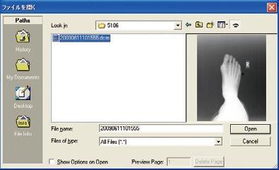


137
NAOMI SYSTEM User Guide
 NAOMI SYSTEM User Guide WM_0810-04 FDA 510(k) Number K062376 This document includes the important information to ensure the safe usage of the item. Before using the system, read through this User Guide
English
 English Specifications Type Power Source Vibration Frequency Maximum Output Power Consumption Water Pressure Lighting NE134 AC120V 50/60Hz AC230V 50/60Hz 28~32kHz 8W Max. 42VA 0.1~0.5MPa (1~5kgf/cm
BIODEX MULTI- JOINT SYSTEM
 BIODEX MULTI- JOINT SYSTEM CONFORMANCE TO STANDARDS 850-000, 840-000, 852-000 FN: 18-139 5/18 Contact information Manufactured by: Biodex Medical Systems, Inc. 20 Ramsey Road, Shirley, New York, 11967-4704
Powered Traction Unit OPERATION MANUAL
 Powered Traction Unit OPERATION MANUAL CONTENTS Symbols Safety precautions Symbol for CAUTION Symbol for CONSULT INSTRUCTIONS FOR USE Symbol for SERIAL NUMBER Symbol for CATALOGUE NUMBER Symbol for AUTHORISED
D C 01/2019 3
 D-0117968-C 01/2019 3 4 D-0117968-C 01/2019 Screw Driver Screw Driver Unplug both the Red & Blue connectors. (see above) Place a small flat head screw driver on the small orange tabs and push down while
Guidance and Declaration - Electromagnetic Compatibility (EMC) for the Delfi PTS ii Portable Tourniquet System
 for the Delfi PTS ii Portable Tourniquet System") Guidance and Declaration - Electromagnetic Compatibility (EMC) for the Delfi TS ii ortable Tourniquet System Guidance and manufacturer s declaration electromagnetic emissions The TS ii ortable Tourniquet
Guidance and Declaration - Electromagnetic Compatibility (EMC) for the Delfi TS ii ortable Tourniquet System Guidance and manufacturer s declaration electromagnetic emissions The TS ii ortable Tourniquet
Technical Specifications Micromedical VisualEyes 505 by Interacoustics
 VisualEyes 505 - Technical Specifications Page 0 Technical Specifications Micromedical VisualEyes 505 by Interacoustics D-0115523-B 2018/02 VisualEyes 505 - Technical Specifications Page 1 Included and
HeRO duet
 HeRO duet CUSTOMER SERVICE TABLE OF CONTENTS TABLE OF CONTENTS OVERVIEW OVERVIEW OVERVIEW OVERVIEW USING HeRO duet USING HeRO duet USING HeRO duet Current HeRO Score HeRO USING HeRO duet USING HeRO duet
MedRx Avant Polar HIT AH-I-MPHITS-5 Effective 11/07/11
 INSTALLATION MANUAL 2 Contents Getting To Know Your AVANT POLAR HIT TM... 4 Setting up the System... 6 Software Installation... 7 Driver Installation Windows 7... 10 Driver Installation Windows XP... 13
General Safety/EMC and Electrical Information for i-limb ultra and i-limb digits
 1. General Safety 1.1 The i-limb ultra and i-limb digits devices are electrical devices, which under certain circumstances could present an electrical shock hazard to the user. Please read the accompanying
#
 INSTALLATION MANUAL 2 Contents Getting To Know Your AVANT POLAR HIT TM... 4 Setting up the System... 6 Software Installation... 7 Driver Installation Windows 7... 10 Driver Installation Windows XP... 13
(c) Medisave UK. Notice. Edition 1. i-pad Operator s Manual
 Medisave UK. Notice. Edition 1. i-pad Operator s Manual") Edition 1 Notice i-pad Operator s Manual CU Medical Systems, Inc. reserves the right to make changes on the device specifications contained in this manual at any time without prior notice or obligation
Edition 1 Notice i-pad Operator s Manual CU Medical Systems, Inc. reserves the right to make changes on the device specifications contained in this manual at any time without prior notice or obligation
Rolyan Splint Pan OPERATION MANUAL. Item # Small Item # Large
 Rolyan Splint Pan OPERATION MANUAL Item #081544816 - Small Item #081544808 Large PLEASE READ THIS ENTIRE MANUAL BEFORE OPERATING YOUR NEW SPLINT PAN. Failure to follow these instructions could result in
Biological Safety. Electromagnetic Compatibility (EMC) Observe the following precautions related to biological safety.
 Observe the following precautions related to biological safety.") Biological Safety Observe the following precautions related to biological safety. WARNING: Non-medical (commercial) grade peripheral monitors have not been verified or validated by SonoSite as being suitable
Biological Safety Observe the following precautions related to biological safety. WARNING: Non-medical (commercial) grade peripheral monitors have not been verified or validated by SonoSite as being suitable
User Instruction Computer Assisted Local Analgesia. 337 Marion, Le Gardeur QC, Canada, J5Z 4W8
 User Instruction Computer Assisted Local Analgesia 1-800-667-9622 337 Marion, Le Gardeur QC, Canada, J5Z 4W8 USER INSTRUCTION Congratulations on your new CALAJECT! Please read these instructions thoroughly
TH008F Multi-function Infrared Forehead Thermometer
 TH008F Multi-function Infrared Forehead Thermometer Specifications Functions Temperature measurement range: Forehead mode: 34~42.2 C (93.2~108 F), Surface mode: -22~80 C (-7.6~176 F) Operating temperature
USER MANUAL MHS-2500I. Please take time to read these instructions before starting to use the scale. Version /17
 USER MANUAL MHS-2500I Please take time to read these instructions before starting to use the scale Version 1.0 05/17 Contents Introduction 3 Product Specification 3 Safety Instructions 4 Explanation of
Electromagnetic compatibility Guidance and manufacturer s declaration DIN EN :2007 (IEC :2007)
") Compressor set Equipment Under Test (EUT) Type 028 Type 047 Type 052 Type 085 Electromagnetic compatibility Guidance and manufacturer s declaration DIN EN 60601-1-2:2007 (IEC 60601-1-2:2007) 2017 PARI
Compressor set Equipment Under Test (EUT) Type 028 Type 047 Type 052 Type 085 Electromagnetic compatibility Guidance and manufacturer s declaration DIN EN 60601-1-2:2007 (IEC 60601-1-2:2007) 2017 PARI
VN415/VO425 Specifications
 VN415/VO425 Specifications Item No. 8105231-1 01/2014 Contents VN415 Specifications... 1 1.1 Technical Standards:...1 1.2 System Requirements:...1 1.3 Included and Optional Parts...2 VO425 Specifications...
DENTAL X-RAY OPERATOR'S INSTRUCTIONS. (for USA) Wall Mount Type...WK
 Wall Mount Type...WK") M 505 DENTAL X-RAY OPERATOR'S INSTRUCTIONS (for USA) Wall Mount Type...WK WARNING This X-ray equipment may be dangerous to patient and operator unless safe exposure factors, operating instructions and
M 505 DENTAL X-RAY OPERATOR'S INSTRUCTIONS (for USA) Wall Mount Type...WK WARNING This X-ray equipment may be dangerous to patient and operator unless safe exposure factors, operating instructions and
Nursing Beds with Dewert drive system
 Nursing Beds with Dewert drive system GB Casa Med Classic 4 / Classic (FS) Casa Med Ultra / Ultra (FS) Casa Med Classic Low Casa Med Classic (FS) 4 / Classic / Casa FS Med / Casa Classic Med Low Ultra
OtoRead - Technical Specifications Page 0. Technical Specifications. OtoRead D A 2017/06
 OtoRead - Technical Specifications Page 0 Technical Specifications OtoRead D-0116698-A 2017/06 OtoRead - Technical Specifications Page 1 OtoRead TM Configuration Overview The OtoReadTM is available in
PHYSIOFLOW Q-LINK TM
 PHYSIOFLOW Q-LINK TM Service Manual Thursday, 20 October 2016 First placing on the market : 18 January 2012 User Manual PhysioFlow Q-Link 1/17 Table of contents 1. General Information... 3 About this manual...
M-400 M-410 M-420 M-430
 USER MANUAL M-400 M-410 M-420 M-430 Please take time to read these instructions before starting to use the scale Version 1.1 10/17 Contents Introduction 3 Product Specification 3 Safety Instructions 4
INTRODUCTION. 4 SAFETY INSTRUCTIONS. 5 ABOUT THIS DEVICE. 6 FIRST OPERATION. 7 THE DISPLAY. 8 ATTACHING THE WRIST SLEEVE. 9 CORRECT MEASUREMENT.
 Table of contents INTRODUCTION.............................. 4 SAFETY INSTRUCTIONS........................ 5 ABOUT THIS DEVICE.......................... 6 FIRST OPERATION............................ 7
SAVI SCOUT Surgical Guidance System. Console Operation Manual
 SAVI SCOUT Surgical Guidance System Console Operation Manual 2 Copyrights and Trademarks 2016 Cianna Medical, Inc. All rights reserved. Patents pending. Cianna Medical and SAVI are registered trademarks
INSTALLATION MANUAL AVANT HIT+ Hearing Instrument Test Chamber.
 INSTALLATION MANUAL AVANT Hearing Instrument Test Chamber HIT+ www.medrx-int.com Contents Getting To Know Your AVANT HIT+. 3 Computer Requirements 4 Setup System. 5 Software Installation.. 6 Sound Card
USER MANUAL M-200. Please take time to read these instructions before starting to use the scale. Version /06
 USER MANUAL M-200 Please take time to read these instructions before starting to use the scale Version 1.0 07/06 Contents Introduction 3 Product Specification 3 Safety Instructions 4 Explanation of Graphic
Operating Manual Infrared thermometer
 Operating Manual Infrared thermometer Model:IT-121 Professional Fast Accurate 1 CONTENTS 1 I n t r o d u c t i o n................ 3 1.1Product intended use 3 2 Basic principle 3 3 Pr o d u c t f e a t
DigiScope II v3 TM Aperture Scope User s Manual
 DigiScope II v3 TM Aperture Scope User s Manual Welcome Thank you for choosing DigiScope II v3 TM Aperture scope! The DigiScope II v3 TM Aperture Scope is an exciting new device to Capture and record the
Technical Data. Electrocardiograph ECG-1250K TD.ECG1250_L. This technical data may be revised or replaced by Nihon Kohden at any time without notice.
 Technical Data Electrocardiograph ECG-1250K This technical data may be revised or replaced by Nihon Kohden at any time without notice. TD.ECG1250_L Specifications ECG input Input impedance: 20 MΩ Electrode
Ceiling Model Ceiling Model for LEDview Plus and Heliodent Plus. Installation Requirements. New as of: English
 New as of: 03.2017 Ceiling Model Ceiling Model for LEDview Plus and Heliodent Plus Installation Requirements English Installation Requirements Ceiling Version = Dentsply Sirona Installation Requirements
#0086.
 INSTALLATION MANUAL Contents Getting to Know Your AVANT REM Speech+... 3 Software Installation... 4 Driver Installation Windows 7... 7 EMC Precautions... 11 Safety... 15 Limited Warranty... 18 #0086 www.medrx-usa.com
: 0089 GTIN
 GTIN: 00894912002050 PRECAUTIONS PROBE Non-invasive probes are for transcutaneous use only Probe transducer tips are thin and delicate. Be careful not to drop or hit the probe tip. After use, protect the
Not for print. Microphone Test Device with SONNET MTD Adapter. User Manual. Cochlear Implants NOT FOR PRINT
 Cochlear Implants Microphone Test Device with SONNET MTD Adapter User Manual AW32690_1.0 (English) Table of contents 1. Table of contents 2. INTRODUCTION 3 Product description 3 3. INTENDED USE INDICATIONS
The following languages can be found on our website: French. German. Spanish. Italian. Swedish. Portuguese. Russian. Dutch.
 Manufactured By: 5580 S. Nogales Hwy. Tucson, Az 85706 USA Telephone: 800-975-7987 Fax: 520-294-6061 www.westmedinc.com PN 74586, Rev. 10 MT Promedt Consulting GmbH Altenhofstr. 80 66386 St. Ingbert, Germany
Operator s Manual External Remote Controller (ERC)
") OM0000-C, 2010-07 Page 1 of 25 Table of Contents 1. SYMBOLS DEFINITION:...3 2. PRODUCT WARNINGS:...6 3. PRODUCT DESCRIPTION:...8 4. COMPONENT IDENTIFICATION:...8 5. INSTRUCTIONS FOR USE:...9 6. EMERGENCY
OM0000-C, 2010-07 Page 1 of 25 Table of Contents 1. SYMBOLS DEFINITION:...3 2. PRODUCT WARNINGS:...6 3. PRODUCT DESCRIPTION:...8 4. COMPONENT IDENTIFICATION:...8 5. INSTRUCTIONS FOR USE:...9 6. EMERGENCY
USER S MANUAL Volk Pictor Plus Fluorescein Angiography (FA) Module For Use with: Volk Pictor Plus
 Module For Use with: Volk Pictor Plus") USER S MANUAL Volk Pictor Plus Fluorescein Angiography (FA) Module For Use with: Volk Pictor Plus IM-080 Rev. A Page 1 of 16 THIS SALES PACKAGE INCLUDES: Model: Fluorescein Angiography (VP2FA) IM-080 Description:
USER S MANUAL Volk Pictor Plus Fluorescein Angiography (FA) Module For Use with: Volk Pictor Plus IM-080 Rev. A Page 1 of 16 THIS SALES PACKAGE INCLUDES: Model: Fluorescein Angiography (VP2FA) IM-080 Description:
H2 Check Operating Manual
 H2 Check Operating Manual Federal (USA) law restricts this device to sale by or on the order of a physician or licensed practitioner. Micro Direct, Inc. 803 Webster Street Lewiston, ME 04240 1-800-588-3381
GTIN:
 GTIN: 00894912002920 TABLE OF CONTENTS Introduction...1 Features...1 Indications for Use...1 Contraindications...1 Warnings & Precautions...2 Controls...3 Operation...4 Recharging the Battery...5 Replacing
Multi-Control Panel for built-in system. Multi Pad for NLX / imd OPERATION MANUAL OM-E0538E 001
 Multi-Control Panel for built-in system Multi Pad for NLX / imd OPERATION MANUAL OM-E0538E 001 Thank you for purchasing Multi Pad. Read this Operation Manual carefully before use for operation instructions
The following symbol indicates that the device is MR-unsafe:
 The following symbol indicates that the device is MR-unsafe: MR Unsafe Do not use this equipment In the MRI scan room Patient must follow the doctor s instructions and should not perform a self-assessment
OPERATOR'S INSTRUCTIONS DENTAL X-RAY MODEL 096
 DENTAL X-RAY MODEL 096 OPERATOR'S INSTRUCTIONS 0197 WARNING: This X-ray equipment may be dangerous to patients and operators unless safe exposure factors and operating instructions are observed. R Table
OPERATOR'S INSTRUCTIONS DX-073 DENTAL X-RAY
 DENTAL X-RAY DX-073 Wall Mount Type...WK Ceiling Mount Type...CK Floor Mount Type...FK1/2 Mobil Mount Type...FM Room Mount Type...RKII OPERATOR'S INSTRUCTIONS 0197 WARNING : This X-ray equipment may be
`bob`=p=^åèìáëáíáçå=råáí
 `bob`=p=^åèìáëáíáçå=råáí qéåüåáå~ä=a~í~= båöäáëü The new CEREC 3 generation for the computer-aided manufacture of ceramic restorations. CAD system for making high-precision optical impressions in the mouth.
WRIST BLOOD PRESSURE MONITOR
 WRIST BLOOD PRESSURE MONITOR Instruction Manual MODEL: ABP801 www.accumed.com TABLE OF CONTENTS INTRODUCTION... 1 NOTES ON SAFETY... 1 ABOUT BLOOD PRESSURE... 3 PRECAUTIONS BEFORE US... 4 FEATURES OF THE
The ideal K-12 science microscope solution. User Guide. for use with the Nova5000
 The ideal K-12 science microscope solution User Guide for use with the Nova5000 NovaScope User Guide Information in this document is subject to change without notice. 2009 Fourier Systems Ltd. All rights
OPERATOR S INSTRUCTIONS (for USA & Canada)
") MODEL 097 DENTAL X-RAY OPERATOR S INSTRUCTIONS (for USA & Canada) WARNING This X-ray equipment may be dangerous to patients and operators unless safe exposure factors and operating instructions are observed.
MODEL 097 DENTAL X-RAY OPERATOR S INSTRUCTIONS (for USA & Canada) WARNING This X-ray equipment may be dangerous to patients and operators unless safe exposure factors and operating instructions are observed.
`bob`=p=^åèìáëáíáçå=råáí=bma
 `bob`=p=^åèìáëáíáçå=råáí=bma qéåüåáå~ä=a~í~= båöäáëü The new CEREC 3 generation for the computer-aided manufacture of ceramic restorations. CAD system for making high-precision optical impressions in the
KoPa Scanner. User's Manual A99. Ver 1.0. SHENZHEN OSTEC OPTO-ELECTRONIC TECHNOLOGY CO.,LTD.
 KoPa Scanner A99 User's Manual Ver 1.0 SHENZHEN OSTEC OPTO-ELECTRONIC TECHNOLOGY CO.,LTD. http://www.ostec.com.cn Content Chapter 1 Start... 1 1.1 Safety Warnings and Precautions... 1 1.2 Installation
User s Manual. Digital Radiography CXDI-60G
 Digital Radiography CXDI-60G User s Manual Before using the instrument, be sure to read this manual thoroughly. Also, read the manuals of other instruments in the system. Keep the manual where it is easily
Veterinary Digital X-Ray System Quick Start Guide
 1 Veterinary Digital X-Ray System Quick Start Guide 2 SOPIX² X-Ray Sensors Quick Start Guide ***PERFORM THIS STEP BEFORE PLUGGING IN THE SENSOR*** Step 1 Load the CD: If you have already plugged in the
Rotating Anode X-Ray Tube Housing Assembly. General Data
 Technical Data TD ROTANODE E7252X E7252FX E7252GX 0197 Rotating Anode X-Ray Tube Housing Assembly High speed rotating anode X-ray tube housing assembly for high energy radiographic and cine-fluoroscopic
Welcome 1. Precaution
 Table of Contents EN Precaution....2 Preparation.. 4 Standard accessories....4 Parts Names & Functions...5 Computer System requirements.... 6 Technical Specifications 7 Install the software.. 7 Start Microscope.8
Optika ISview. Image acquisition and processing software. Instruction Manual
 Optika ISview Image acquisition and processing software Instruction Manual Key to the Instruction Manual IS is shortened name used for OptikaISview Square brackets are used to indicate items such as menu
Welch Allyn Home Scale (T- RPM-SCALE100)
") Welch Allyn Home Scale (T- RPM-SCALE100) Directions for use 901077 Weight scale, Software Version 1.0 2017 Welch Allyn. All rights are reserved. To support the intended use of the product described in
Welch Allyn Home Scale (T- RPM-SCALE100) Directions for use 901077 Weight scale, Software Version 1.0 2017 Welch Allyn. All rights are reserved. To support the intended use of the product described in
L NKTEMP. Non-contact. Infrared Thermometer. User Manual LMP001
 L NKTEMP Non-contact Infrared Thermometer User Manual LMP001 TABLE OF CONTENTS Product Description Intended Use Product Features Safety Precautions Using the Thermometer Taking a Measurement Temperature
CHAPTER1: QUICK START...3 CAMERA INSTALLATION... 3 SOFTWARE AND DRIVER INSTALLATION... 3 START TCAPTURE...4 TCAPTURE PARAMETER SETTINGS... 5 CHAPTER2:
 Image acquisition, managing and processing software TCapture Instruction Manual Key to the Instruction Manual TC is shortened name used for TCapture. Help Refer to [Help] >> [About TCapture] menu for software
S5-ADU. Front... 4 Rear... 4
 Trantec ANTENNA DISTRIBUTOR INSTRUCTION MANUAL S5-ADU Thank you for purchasing TRANTEC Antenna Distributor. Please carefully follow the instructions in this manual to ensure long, trouble-free use of your
GXCapture 8.1 Instruction Manual
 GT Vision image acquisition, managing and processing software GXCapture 8.1 Instruction Manual Contents of the Instruction Manual GXC is the shortened name used for GXCapture Square brackets are used to
OPERATOR S MANUAL AN APPLIED DIGITAL COMPANY
 OPERATOR S MANUAL AN APPLIED DIGITAL COMPANY Contents: VeriChip H2 Reader Assembly Part Number 600-000515-000 (includes all of the following): USER INSTRUCTIONS Description Part Number Description The
Central Blood Pressure Meter Model cbp301. Operating Manual
 Central Blood Pressure Meter Model cbp301 Operating Manual Document cbp301-009 Issue 4 September 2011 Contents Introduction... 3 Package Contents... 5 Warnings and Cautions... 6 Contraindications... 7
LumaSpec 800S User Manual
 LumaSpec 800S User Manual Worldwide distribution VERSION 09112014 Prior Scientific, Ltd Cambridge, UK Prior Scientific, Inc Rockland, MA. USA Prior Scientific, GmbH Jena, Germany Prior Scientific KK Tokyo,
Nerve stimulator TWISTER
 Nerve stimulator TWISTER INSTRUCTIONS FOR USE Softwareversion 1.19 Manufacturer: Dr. Langer Medical GmbH Fabrik Sonntag, Haus 4a 79183 Waldkirch Germany Table of contents 1 Intended use... 5 2 Common
23070 / Digital Camera Owner s Manual
 23070 / 23072 Digital Camera Owner s Manual 2007 Sakar International, Inc. All rights reserved. 2007 Crayola Windows and the Windows logo are registered trademarks of Microsoft Corporation. All other trademarks
F100 Tabletop Document Folder
 F100 Tabletop Document Folder 10/2018 OPERATOR MANUAL FIRST EDITION Single Fold Letter Fold Z-fold Double Fold Specifications Paper size 11" & 14" Paper weight 60g/m 2 to 90g/m 2 Some recycled paper and
Table of Contents. Sound-Eklin rev052511
 User Manual Table of Contents Important Safety Information...1 Chapter 1: Opening TruDR...3 Chapter 2: Patient Information...4 Searching and Adding Patients...4 Editing an Existing Patient s Information...6
USER MANUAL PV 360. Vidifox Document Camera
 Vidifox Document Camera PV 360 USER MANUAL Please read this User Manual thoroughly before you use the document camera. Keep the CD-ROM in a convenient place so you can use it quickly if you need to. Please
Contents. Densely aligned CCD sensors with our own unique technology
 Contents From CR to DR... 02 No.1 Share in DR Market... 04 Features... 06 Operation... 08 Optional Items... 10 Specifications... 12 Support / After-Service... 13 Densely aligned CCD sensors with our own
Combo Scanner. User Manual
 Combo Scanner User Manual I. Unpack the Combo Scanner Backlight Holder Combo Scanner Business card Fixture Photo/Business Card Holder User Manual Quick Installation Guide Note This Combo Scanner supports
Connevans.info. DeafEquipment.co.uk. This product may be purchased from Connevans Limited secure online store at
 Connevans.info Solutions to improve the quality of life Offering you choice Helping you choose This product may be purchased from Connevans Limited secure online store at www.deafequipment.co.uk DeafEquipment.co.uk
INSTRUCTIONS FOR YOUR NEW PLASMAFLOW. Vascular Therapy System (Compressible Limb Sleeve Device)
") INSTRUCTIONS FOR YOUR NEW PLASMAFLOW Vascular Therapy System (Compressible Limb Sleeve Device) Customer Service Toll Free: 888-508-0712 Email: CustomerService@manamed.net Web: www.manamed.net 1511 W. Alton
INSTRUCTIONS FOR YOUR NEW PLASMAFLOW Vascular Therapy System (Compressible Limb Sleeve Device) Customer Service Toll Free: 888-508-0712 Email: CustomerService@manamed.net Web: www.manamed.net 1511 W. Alton
Quick Start Guide. Setup and Scanning. Try the Additional Features. English
 English Quick Start Guide Be sure to install the software programs before connecting the scanner to the computer! Setup and Scanning Check the Package Contents p.3 Install the Software Windows Macintosh
This product may malfunction due to electromagnetic waves caused by portable
 1 IMPORTANT NOTICE This product may malfunction due to electromagnetic waves caused by portable personal telephones, transceivers, radio-controlled toys, etc. Be sure to avoid having objects such as, which
WELCOME WHAT S IN THE BOX
 WELCOME Congratulations on purchasing your Visioneer PaperPort flatbed scanner. With your scanner, you can quickly scan paper documents and color photos to place their electronic images on your computer.
Technical Data TD. X-Ray FLAT PANEL IMAGER FDX3543RP FEATURING: Active Area: 35(H) 43(V)cm (14 17 ) Excellent Sensitivity & Resolution
 43(V)cm (14 17 ) Excellent Sensitivity & Resolution") Technical Data TD X-Ray FLAT PANEL IMAGER FDX3543RP FEATURING: Active Area: 35(H) 43(V)cm (14 17 ) Excellent Sensitivity & Resolution Excellent Image Quality Excellent Reliability Excellent Sensitivity
Technical Data TD X-Ray FLAT PANEL IMAGER FDX3543RP FEATURING: Active Area: 35(H) 43(V)cm (14 17 ) Excellent Sensitivity & Resolution Excellent Image Quality Excellent Reliability Excellent Sensitivity
English User's Guide
 User's Guide Imacon Flextight 343 2 2003 Imacon A/S. All rights reserved. Imacon Flextight 343 User's Guide, Part No 70030009, revision B. The information in this manual is furnished for informational
Digital Color Printer
 3-858-635-12 (1) Digital Color Printer Operating Instructions Before operating the unit, please read this manual thoroughly and retain it for future reference. This PRINTER is designed to use PRINT PACK
Quick Start Guide. Setup and Scanning. Try the Additional Features. English
 English Quick Start Guide Be sure to install the software programs before connecting the scanner to the computer! Setup and Scanning Check the Package Contents p.3 Install the Software Windows Macintosh
For customers in Canada This Class B digital apparatus meets all requirements of the Canadian Interference-Causing Equipment Regulations.
 User manual For customers in North and South America For customers in USA This device complies with Part 15 of the FCC rules. Operation is subject to the following two conditions: (1) This device may not
AeroDR Stitching System
 DIRECT DIGITIZER Operation Manual AeroDR Stitching System EN 06 Contents Introduction................. 5 Introduction.............................. 6 Summary of usability specifications (for IEC/EN 60601-1-6,
FCC Notice (U.S.A. Only)
") Quick Start Guide Please read this guide before operating this scanner. After you finish reading this guide, store it in a safe place for future reference. Table of Contents Package Contents... 1 Scanning
Quick Start Guide Please read this guide before operating this scanner. After you finish reading this guide, store it in a safe place for future reference. Table of Contents Package Contents... 1 Scanning
Happy Link Software INSTRUCTION MANUAL
 Happy Link Software INSTRUCTION MANUAL 101001E-3 HAPPY Contents Regarding this software Normal Operation -------------------------------------------------------------------------------------------------
DC300. Document Camera USER MANUAL
 DC300 Document Camera USER MANUAL 1 Please read this manual carefully before operating the document camera and keep it for reference. PRECAUTIONS NOTICE: PLEASE READ CAREFULLY BEFORE USE Use the document
POCKET AIR. Portable Nebulizer. Instruction Manual MBPN002 / MB / MB05006
 R POCKET AIR Portable Nebulizer Instruction Manual MBPN002 / MB0500300/ MB05006 Table of Contents General information... 1 Intended Use... 2 Safety Precautions... 3 Explanation of Symbols... 4 Package
Film2USB Converter. Quick Start Guide & User s Manual. Model Number F2USB-05
 Film2USB Converter Quick Start Guide & User s Manual Model Number F2USB-05 www.film2usb.com www.clearclicksoftware.com Table of Contents Safety Precautions... 3 Package Contents... 4 Description of Parts...
POWERED MONITOR SPEAKER MSP10STUDIO
 POWERED MONITOR SPEAKER MSP10STUDIO Owner s manual Mode d emploi Bedienungsanleitung Manual de instrucciones M Thank you for purchasing the Yamaha MSP10STUDIO powered monitor speaker system. The MSP10STUDIO
Table 1. Placing the Sensor in the Sensor Cradle. Step Instruction Illustration
 Table 1. Placing the Sensor in the Sensor Cradle Step Instruction Illustration 1. A. Check "U-shaped" Positioner. The number pointing towards the Sensor (1 or 2) must correspond with the Sensor's size.
SPAC265-8W. AC-DC power supply module. Features. Description. Applications
 AC-DC power supply module Datasheet production data Features Open frame switch mode power supply European input voltage range Single output 5 V, 8 W peak power, 4 W continuous operating mode EMC compliance
On-Line Cardio Theater Wireless Digital Transmitter Installation and Instruction Manual
 On-Line Cardio Theater Wireless Digital Transmitter Installation and Instruction Manual Full installation instructions accompany your Cardio Theater equipment order. This On-Line version of our Installation/Instruction
FUJITSU TWAIN 32 Scanner Driver. Scanner Utility for Microsoft Windows Version User's Guide
 P3PC- E417-02EN FUJITSU TWAIN 32 Scanner Driver Scanner Utility for Microsoft Windows Version 9.10 User's Guide For Use with Microsoft Windows 98, Windows Me, Windows 2000 and Windows XP Introduction
S100 Webcam. User s Manual
 S100 Webcam User s Manual Kodak and the Kodak trade dress are trademarks of Eastman Kodak Company used under license. 2009 Sakar International, Inc. All rights reserved. WINDOWS and the WINDOWS logo are
KODAK Dental Imaging Software. Quick Start Guide
 KODAK Dental Imaging Software Quick Start Guide Notice Congratulations on your purchase of The KODAK Dental Imaging Software. Thank you for your confidence in our products and we will do all in our power
Product Name: COMPER SMART DOPPLER FETAL MONITOR. Product Model: DFMX
 DFMX User Manual Document Num: History of Change: User Manual JS02114DFMX V1.0 Issue Date: Version: Editor: Reviewer: Approver: Date:xx-xx-xx Date:xx-xx-xx Date:xx-xx-xx Product Name: COMPER SMART DOPPLER
Introducing the Pixium Portable System
 Introducing the Pixium Portable System. Congratulations on your purchase of the Pixium Portable system. The Pixium Portable is a mobile radiography system that converts static radiographic images into
Quick Start Guide. Setup and Scanning. Try the Additional Features. English
 English Quick Start Guide Be sure to install the software programs before connecting the scanner to the computer! Setup and Scanning Check the Package Contents p.3 Install the Software Windows Macintosh
TEST REPORT... 1 CONTENT...
 CONTENT TEST REPORT... 1 CONTENT... 2 1 TEST RESULTS SUMMARY... 3 2 EMC RESULTS CONCLUSION... 4 3 LABORATORY MEASUREMENTS... 6 4 EMI TEST... 7 4.1 CONTINUOUS CONDUCTED DISTURBANCE VOLTAGE TEST... 7 4.2
User instructions for the ABI-system 100
 User instructions for the ABI-system 100 0124 User instructions for the ABI-system 100 1 ABI-system 100 2 CA04 cuffs (for upper arms) 2 CL04 cuffs (for legs) 1 ABI software CD 1 USB cable 1 boso mains
Magic Wand Portable Scanner with Auto-Feed Dock. PDSDK-ST470-VP-BX2 User Manual
 Magic Wand Portable Scanner with Auto-Feed Dock PDSDK-ST470-VP-BX2 User Manual Table of Contents 1. KEY FEATURES... 2 2. FUNCTIONAL PARTS... 2 3. EXPLANATION OF THE STATUS ICONS... 4 4. GETTING STARTED...
Digital Portable Overhead Document Camera LV-1010
 Digital Portable Overhead Document Camera LV-1010 Instruction Manual 1 Content I Product Introduction 1.1 Product appearance..3 1.2 Main functions and features of the product.3 1.3 Production specifications.4