The OOF Holography Technique: Correcting the Effects of Gravity and Thermal Gradients on Large Filled-Aperture Telescopes
|
|
|
- Christopher Bishop
- 5 years ago
- Views:
Transcription
1 The OOF Holography Technique: Correcting the Effects of Gravity and Thermal Gradients on Large Filled-Aperture Telescopes B. Nikolic MRAO, Cavendish Laboratory/Kavli Institute for Cosmplogy University of Cambridge September 2010 B. Nikolic (University of Cambridge) OOF Holography September / 66
2 People University of Cambridge R. E. Hills, J. S. Richer, A. N. Lasenby NRAO R. M. Prestage, D. S. Balser, C. Chandler, T. Hunter, B. Mason, M. Mello U/Penn S. Dicker, P. Korngut B. Nikolic (University of Cambridge) OOF Holography September / 66
3 Outline Introduction 1 Introduction 2 The OOF Holography Technique 3 Simulations 4 Application to the GBT 5 Conclusions B. Nikolic (University of Cambridge) OOF Holography September / 66
4 Introduction Requirements for telescope surface Ruze law: [ ( ) ] 4πσ 2 Efficiency exp λ (1) 1 σ: Root-mean-square wavefront error λ: Observing wavelength ε eff 1 2 λ 30 λ 20 λ 10 Note: this is surface efficiency, not aperture efficiency B. Nikolic (University of Cambridge) OOF Holography September / 66 σ/λ
5 Introduction Requirements for telescope surface Ruze law: [ ( ) ] 4πσ 2 Efficiency exp λ (1) 1 σ: Root-mean-square wavefront error λ: Observing wavelength ε eff 850 µm 1 2 ALMA 350 µm 350 µm 3.3 mm λ 30 λ 20 λ 10 Note: this is surface efficiency, not aperture efficiency B. Nikolic (University of Cambridge) OOF Holography September / 66 σ/λ
6 Introduction Causes of deformation Factors affecting telescope surface accuracy Sources of inaccuracy: Manufacturing accuracy of panels and subsequent deformation Setting error: static Setting requires 1:10 6 measurement accuracy Residual gravitation deformation: repeatable (Major gravity deformations are compensated by homology) Thermal deformation: 60 minute timescale Wind: short timescale Ageing effects Characteristic length scale or errors: Gravity, thermal effects, tend to cause large-scale errors Wind is likely to be large-scale Setting error can be both large- and small-scale B. Nikolic (University of Cambridge) OOF Holography September / 66
7 Introduction Causes of deformation Factors affecting telescope surface accuracy Sources of inaccuracy: Manufacturing accuracy of panels and subsequent deformation Setting error: static Setting requires 1:10 6 measurement accuracy Residual gravitation deformation: repeatable (Major gravity deformations are compensated by homology) Thermal deformation: 60 minute timescale Wind: short timescale Ageing effects Characteristic length scale or errors: Gravity, thermal effects, tend to cause large-scale errors Wind is likely to be large-scale Setting error can be both large- and small-scale B. Nikolic (University of Cambridge) OOF Holography September / 66
8 Telescope natural limits Introduction Causes of deformation von Hoerner (1967), 1967AJ V B. Nikolic (University of Cambridge) OOF Holography September / 66
9 Introduction Causes of deformation Telescope natural limits Gravity & thermal effects and the homology principle [Data partially from Radford & Woody, 2009, NA URSI meeting, Boulder] B. Nikolic (University of Cambridge) OOF Holography September / 66
10 Introduction Causes of deformation Active radio-telescopes Key concept Compensate rather than prevent surface error 1 Homology 2 Active surface B. Nikolic (University of Cambridge) OOF Holography September / 66
11 Introduction Measuring deformations Telescope measurement techniques Almost all telescopes end up using some combination of these no single technique can satisfy all requirements: Conventional surveying Photogrammetry Interferometric holography using astronomical sources Transmitter with-phase holography Transmitter phase-retrieval holography Out-Of-Focus (OOF) holography (or, phase-retrieval holography with astronomical sources) B. Nikolic (University of Cambridge) OOF Holography September / 66
12 Outline The OOF Holography Technique 1 Introduction 2 The OOF Holography Technique 3 Simulations 4 Application to the GBT 5 Conclusions B. Nikolic (University of Cambridge) OOF Holography September / 66
13 The OOF Holography Technique Simulated Out-Of-Focus Beams, Perfect Telescope or point-spread-functions In-Focus -ve De-Focus +ve De-Focus 12 db of taper De-focus: λ of path across the aperture B. Nikolic (University of Cambridge) OOF Holography September / 66
 Surface Errors (Projected to an imaginary surface) B.")
14 The OOF Holography Technique A surface with random large-scale errors Receiver Response (Taper/Apodisation/...) Surface Errors (Projected to an imaginary surface) B. Nikolic (University of Cambridge) OOF Holography September / 66

15 The OOF Holography Technique Simulated Out-Of-Focus Beams In-Focus -ve De-Focus +ve De-Focus 12 db of taper Random large-scale surface error added to the surface B. Nikolic (University of Cambridge) OOF Holography September / 66


 OOF")
16 The OOF Holography Technique Simulated Out-Of-Focus Beams, with noise In-Focus -ve De-Focus +ve De-Focus 12 db of taper Signal-To-Noise: 100:1 per pixel B. Nikolic (University of Cambridge) OOF Holography September / 66
17 The OOF Holography Technique Aims of the OOF technique Measure the complete optical aberrations in a telescope Surface errors + mis-collimation + receiver optics... Rapidly I.e., under 1/2 hour Currently at the GBT, measurements take < 5 minutes As a function of elevation, time of day, etc Measure the effect of gravity Measure the thermal deformation Without extra equipment Makes it easy to interleave with science observations (Zero materials cost) B. Nikolic (University of Cambridge) OOF Holography September / 66
18 The OOF Holography Technique Technique overview How: Use beam power maps Astronomical receivers Astronomical sources Trick I: Obtain the beam-maps relatively far out-of-focus Breaks degeneracies Reduces the required signal to noise Trick II: Appropriate parametrisation of errors We use Zernike Polynomials Trades required signal to noise with resolution Low-orders correspond to classical/common aberrations Relatively low-resolution Usually not be high-enough resolution for panel-to-panel errors B. Nikolic (University of Cambridge) OOF Holography September / 66

 OOF Holography")
19 The OOF Holography Technique Basics: Fourier relationship between aperture and far-field Aperture Far-field amplitude & phase FFT B. Nikolic (University of Cambridge) OOF Holography September / 66
20 The OOF Holography Technique Basics: Beam maps (power-only) Aperture FFT + 2 Power only B. Nikolic (University of Cambridge) OOF Holography September / 66
21 The OOF Holography Technique The OOF Holography Algorithm A classic non-linear inverse problem: The forward model Conceptually relatively simple: only requires an FFT Beam switching, non-point like sources, atmospheric effects, off-axis pixels, etc., make it complex Parametrisation of surface errors Zernike polynomials Likelihood of data given model Take normally distributed errors Pointing errors, residual atmospheric emission, gain fluctuation can also be important Solver algorithm Levenberg-Marquardt maximum-likelihood MCMC B. Nikolic (University of Cambridge) OOF Holography September / 66
22 The OOF Holography Technique The OOF Holography Algorithm Parametrisation Minimise Surface Errors Defocus Aperture phase Aperture Amplitude Residual FFT Telescope Beam Observing Strategy Model Observation B. Nikolic (University of Cambridge) OOF Holography September / 66
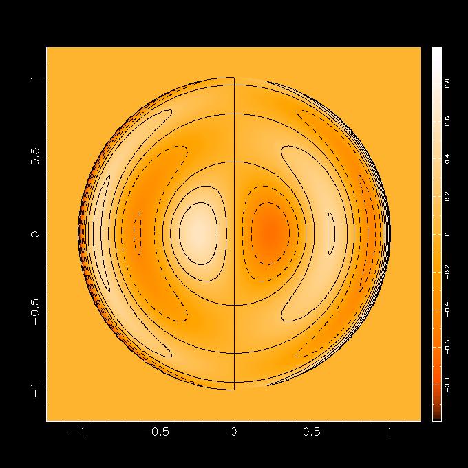
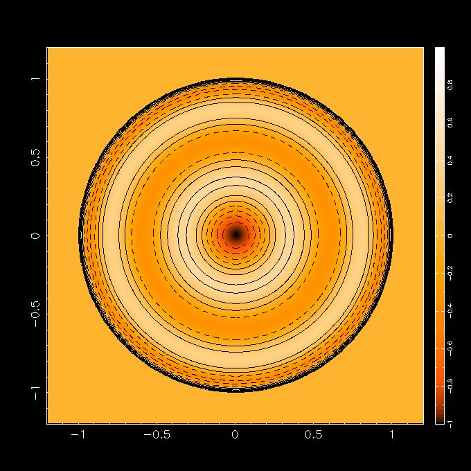
23 The OOF Holography Technique Zernike Polynomials: n = 1 Vertical Pointing Horizontal Pointing B. Nikolic (University of Cambridge) OOF Holography September / 66
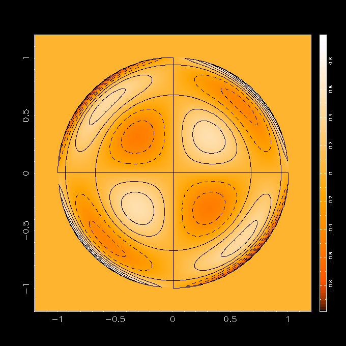
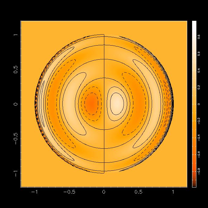
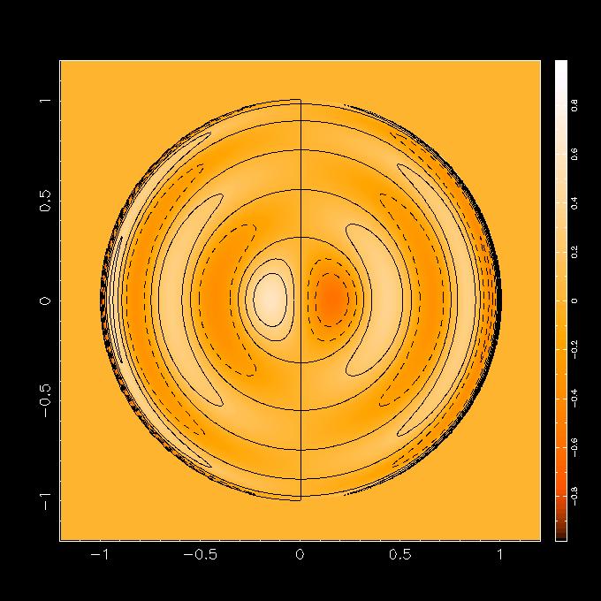
24 The OOF Holography Technique Zernike Polynomials: n = 2 X astigmatism Focus + Astigmatism B. Nikolic (University of Cambridge) OOF Holography September / 66
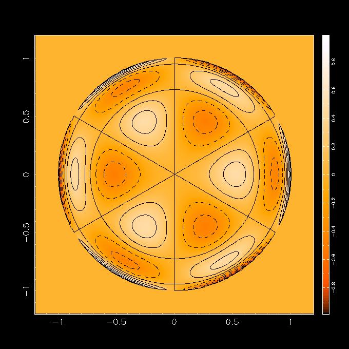
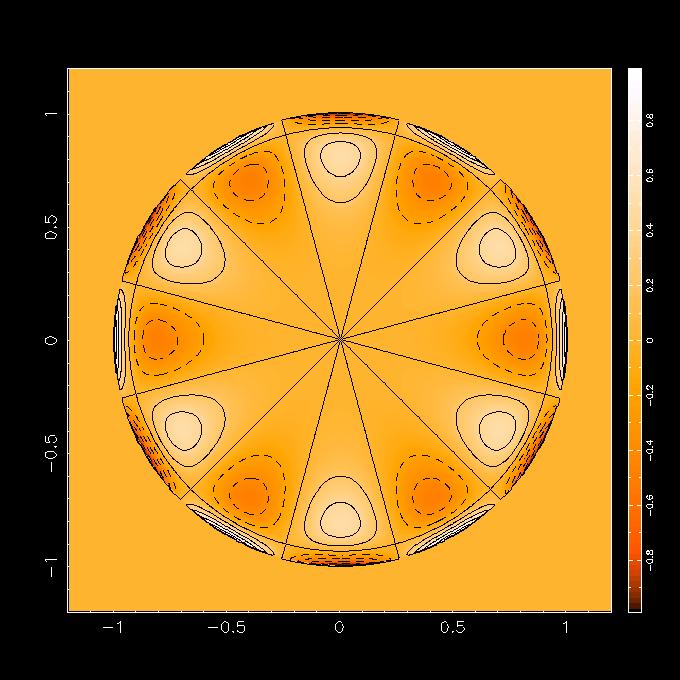
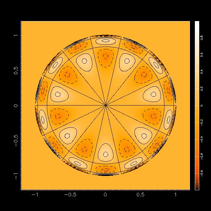
25 The OOF Holography Technique Zernike Polynomials: n = 3 Trefoil Coma B. Nikolic (University of Cambridge) OOF Holography September / 66
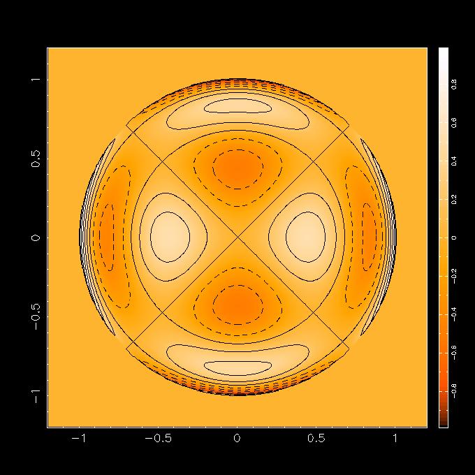
26 The OOF Holography Technique Zernike Polynomials: n = 4 Spherical B. Nikolic (University of Cambridge) OOF Holography September / 66
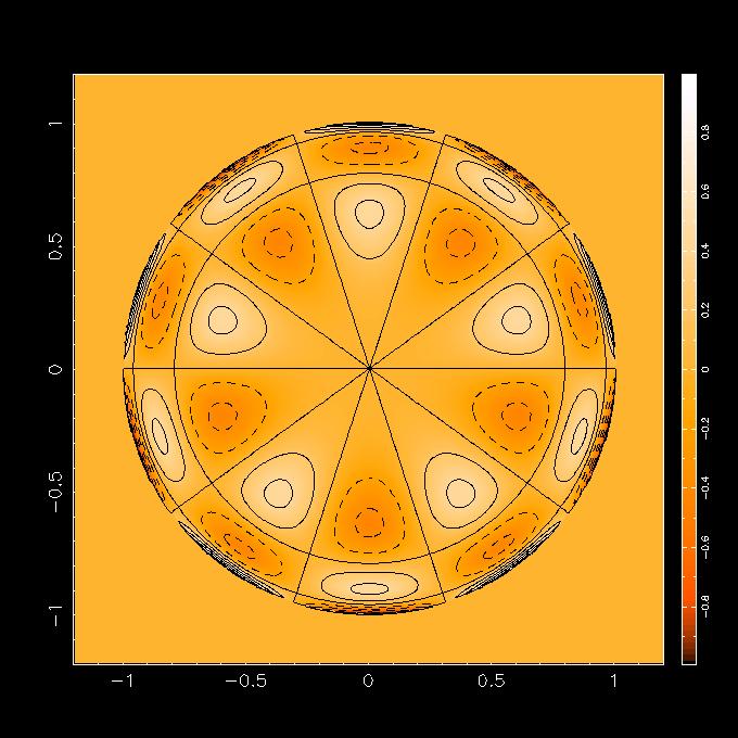
27 The OOF Holography Technique Zernike Polynomials: n = 5 2nd Order Coma B. Nikolic (University of Cambridge) OOF Holography September / 66
28 The OOF Holography Technique Suitable astronomical sources Ideal sources are strong and point-like = at longer mm-wavelengths quasars usually ideal targets At short millimetre and sub-mm wavelengths quasars may be weak = can use planets: Extended sources not a problem, sharp edges most important Need to model the extended source and any substructure (limb darkening; rings!) Spectral line observations also possible: High S/N with masers Excellent atmospheric rejection Can be problems reading out fast enough Fewer sources than quasars B. Nikolic (University of Cambridge) OOF Holography September / 66
29 Outline Simulations 1 Introduction 2 The OOF Holography Technique 3 Simulations 4 Application to the GBT 5 Conclusions B. Nikolic (University of Cambridge) OOF Holography September / 66
30 Simulations Simulations Overview Topics: Required signal-to-noise Effects of pointing errors Optimum size of defocus Maximum resolution that can be achieved A&A paper Nikolic et al, Also other talks on the OOF technique: bn204/publications/publicationlist.html B. Nikolic (University of Cambridge) OOF Holography September / 66
31 Simulations Simulations: Error on the retrieved surface Vs S/N ǫ (rad) Noise/Signal B. Nikolic (University of Cambridge) OOF Holography September / 66
32 Outline Application to the GBT 1 Introduction 2 The OOF Holography Technique 3 Simulations 4 Application to the GBT 5 Conclusions B. Nikolic (University of Cambridge) OOF Holography September / 66
 OOF Holography September")
33 Application to the GBT The Green Bank Telescope B. Nikolic (University of Cambridge) OOF Holography September / 66
34 Application to the GBT Why GBT? A fully active, continuously adjusted, primary surface = instant application of corrections The GBT is not exactly homologous Non-homologous deformation is corrected by the active surface This correction initially calculated using a finite-element model Not quite accurate enough needed a refinement Exposed, all-steel, construction is susceptible to thermal deformation Large collecting area = high signal to noise 2209 actuators = OOF holography can not be used for initial setting B. Nikolic (University of Cambridge) OOF Holography September / 66
35 Application to the GBT Application at the GBT Modelling residual gravitational errors Measure surface errors over wide range of elevations During night-time to minimise thermal effects Construct a model for how telescope deforms as function of elevation = Equivalent of measuring the focus-curve but for many more possible deformations Near real-time measurement and correction of thermal error Measure surface using bright quasar Apply correct immediately Repeat every 1 hour = Equivalent of a peak and focus measurement, but again for many more deformation modes B. Nikolic (University of Cambridge) OOF Holography September / 66
36 Application to the GBT Modelling gravitational deformation Modelling Gravitational Deformation Obtained 37 measurements over three sessions covering a range of elevations Used the dual-beam Q-band receiver (42 GHz) Fit a sin(θ) + b cos(θ) + c to each Zernike coefficient individually 8 6 N θ (deg) B. Nikolic (University of Cambridge) OOF Holography September / 66

37 Application to the GBT GBT Observation at Q-Band Modelling gravitational deformation B. Nikolic (University of Cambridge) OOF Holography September / 66

38 Application to the GBT Modelling gravitational deformation Sample GBT Observation at Q-Band: The Retrieved Surface B. Nikolic (University of Cambridge) OOF Holography September / 66
39 Application to the GBT Modelling gravitational deformation Gravitational Model: Vertical Coma Phase (rad) n = 3, l = Elevation (deg) B. Nikolic (University of Cambridge) OOF Holography September / 66
40 Application to the GBT Modelling gravitational deformation Gravitational Model: Horizontal Coma Phase (rad) n = 3, l = Elevation (deg) B. Nikolic (University of Cambridge) OOF Holography September / 66
41 Application to the GBT Modelling gravitational deformation Gravitational Model: Trefoil Phase (rad) n = 3, l = Elevation (deg) B. Nikolic (University of Cambridge) OOF Holography September / 66
42 Application to the GBT Modelling gravitational deformation Gravitational Model: Trefoil Phase (rad) n = 3, l = Elevation (deg) B. Nikolic (University of Cambridge) OOF Holography September / 66
43 Application to the GBT Modelling gravitational deformation Gravitational Model: Astigmatism Phase (rad) n = 2, l = Elevation (deg) B. Nikolic (University of Cambridge) OOF Holography September / 66
44 Application to the GBT Modelling gravitational deformation Gravitational Model: Astigmatism Phase (rad) n = 2, l = Elevation (deg) B. Nikolic (University of Cambridge) OOF Holography September / 66
45 Application to the GBT Modelling gravitational deformation Gravitational Model Phase (rad) Phase (rad) Phase (rad) n = 4, l = n = 4, l = n = 4, l = Elevation (deg) Elevation (deg) Elevation (deg) Phase (rad) Phase (rad) Phase (rad) n = 4, l = n = 4, l = n = 5, l = Elevation (deg) Elevation (deg) Elevation (deg) Phase (rad) Phase (rad) Phase (rad) n = 5, l = n = 5, l = n = 5, l = Elevation (deg) Elevation (deg) Elevation (deg) B. Nikolic (University of Cambridge) OOF Holography September / 66
46 Application to the GBT Modelling gravitational deformation Gravitational Model: Efficiency 0.55 FEM Only 0.55 FEM and OOF gravitational model ηa 0.4 ηa E (degrees) E (degrees) Measured total aperture efficiencies at Q-band (42 GHz) B. Nikolic (University of Cambridge) OOF Holography September / 66


 OOF Holography")
47 Application to the GBT Thermal correction GBT Observation at 90 GHz with MUSTANG B. Nikolic (University of Cambridge) OOF Holography September / 66

48 Application to the GBT Thermal correction Night-time thermal deformation from MUSTANG B. Nikolic (University of Cambridge) OOF Holography September / 66
49 Application to the GBT Example with snow/ice in dish Performance in extreme conditions: in-focus beam Probably significant ice/snow in the dish In-Focus beam at 90 GHz B. Nikolic (University of Cambridge) OOF Holography September / 66
50 Application to the GBT Example with snow/ice in dish Performance in extreme conditions In-Focus +ve De-Focus -ve De-Focus B. Nikolic (University of Cambridge) OOF Holography September / 66
51 Application to the GBT Example with snow/ice in dish Performance in extreme conditions: Fitting n = 2 In-Focus +ve De-Focus -ve De-Focus B. Nikolic (University of Cambridge) OOF Holography September / 66
52 Application to the GBT Example with snow/ice in dish Performance in extreme conditions: Fitting n = 3 In-Focus +ve De-Focus -ve De-Focus B. Nikolic (University of Cambridge) OOF Holography September / 66
53 Application to the GBT Example with snow/ice in dish Performance in extreme conditions: Fitting n = 4 In-Focus +ve De-Focus -ve De-Focus B. Nikolic (University of Cambridge) OOF Holography September / 66
54 Application to the GBT Example with snow/ice in dish Performance in extreme conditions: Fitting n = 5 In-Focus +ve De-Focus -ve De-Focus B. Nikolic (University of Cambridge) OOF Holography September / 66
55 Application to the GBT Example with snow/ice in dish Performance in extreme conditions: Fitting n = 6 In-Focus +ve De-Focus -ve De-Focus B. Nikolic (University of Cambridge) OOF Holography September / 66
56 Application to the GBT Example with snow/ice in dish Performance in extreme conditions: Fitting n = 7 In-Focus +ve De-Focus -ve De-Focus B. Nikolic (University of Cambridge) OOF Holography September / 66
57 Application to the GBT Example with snow/ice in dish Performance in extreme conditions: Fitting n = 8 In-Focus +ve De-Focus -ve De-Focus B. Nikolic (University of Cambridge) OOF Holography September / 66

58 Application to the GBT Inferred surface errors n = 2 Example with snow/ice in dish B. Nikolic (University of Cambridge) OOF Holography September / 66

59 Application to the GBT Inferred surface errors n = 3 Example with snow/ice in dish B. Nikolic (University of Cambridge) OOF Holography September / 66
60 Application to the GBT Inferred surface errors n = 4 Example with snow/ice in dish B. Nikolic (University of Cambridge) OOF Holography September / 66
61 Application to the GBT Inferred surface errors n = 5 Example with snow/ice in dish B. Nikolic (University of Cambridge) OOF Holography September / 66

62 Application to the GBT Inferred surface errors n = 6 Example with snow/ice in dish B. Nikolic (University of Cambridge) OOF Holography September / 66

63 Application to the GBT Inferred surface errors n = 7 Example with snow/ice in dish B. Nikolic (University of Cambridge) OOF Holography September / 66

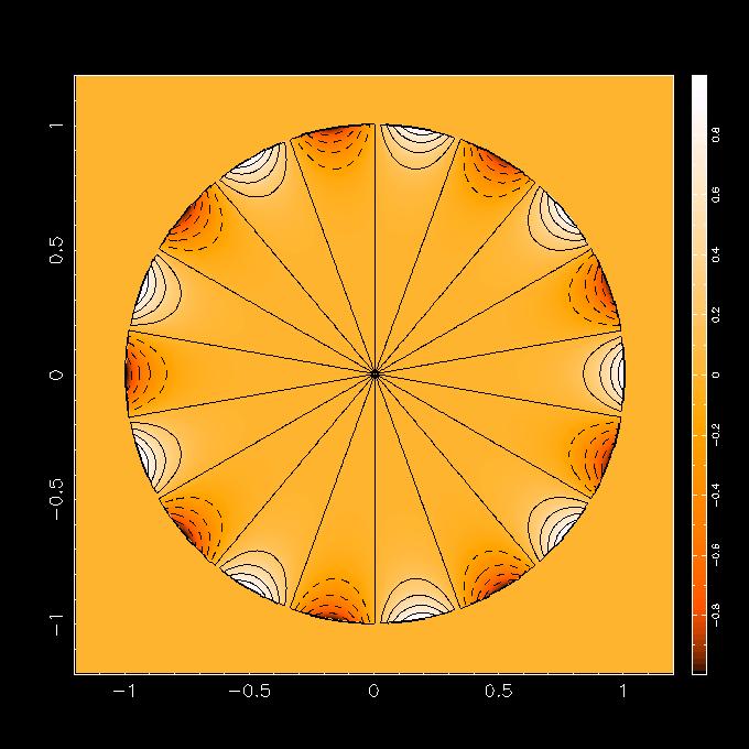
64 Application to the GBT Inferred surface errors n = 8 Example with snow/ice in dish B. Nikolic (University of Cambridge) OOF Holography September / 66

65 Application to the GBT Detailed comparison of beams In-focus Example with snow/ice in dish Observed beam Best-fit beam with n = 8 B. Nikolic (University of Cambridge) OOF Holography September / 66
66 Application to the GBT Detailed comparison of beams +ve defocus Example with snow/ice in dish Observed beam Best-fit beam with n = 8 B. Nikolic (University of Cambridge) OOF Holography September / 66
67 Application to the GBT Detailed comparison of beams -ve defocus Example with snow/ice in dish Observed beam Best-fit beam with n = 8 B. Nikolic (University of Cambridge) OOF Holography September / 66
68 Application to the GBT Example with snow/ice in dish Performance in extreme conditions: High-res (n = 12) In-Focus +ve De-Focus -ve De-Focus B. Nikolic (University of Cambridge) OOF Holography September / 66
 OOF Holography September 2010 53 /")
69 High-res surface map Application to the GBT Example with snow/ice in dish B. Nikolic (University of Cambridge) OOF Holography September / 66
70 Application to the GBT Example with snow/ice in dish Zernike polynomials used in the high-res map I B. Nikolic (University of Cambridge) OOF Holography September / 66


71 Application to the GBT Example with snow/ice in dish Zernike polynomials used in the high-res map II B. Nikolic (University of Cambridge) OOF Holography September / 66


72 Application to the GBT Example with snow/ice in dish Zernike polynomials used in the high-res map III B. Nikolic (University of Cambridge) OOF Holography September / 66


73 Application to the GBT Example with snow/ice in dish Zernike polynomials used in the high-res map IV B. Nikolic (University of Cambridge) OOF Holography September / 66


 OOF")
74 Application to the GBT Example with snow/ice in dish Zernike polynomials used in the high-res map V B. Nikolic (University of Cambridge) OOF Holography September / 66
75 Application to the GBT Example with snow/ice in dish Basic results OOF technique eliminated non-panel gravitational error Can be used very effectively to measure thermal deformation Used to also correct thermal deformation B. Nikolic (University of Cambridge) OOF Holography September / 66
76 Application to the GBT Example with snow/ice in dish Recent highlights Use of the 64-pixel MUSTANG 90 GHz camera to greatly accelerate acquisition and accuracy of measurements AutoOOF : Automatised acquisition, processing and application of corrections with minimum intervention Routine application of thermal corrections during scientific observations Calculating the pointing and focus from OOF observations B. Nikolic (University of Cambridge) OOF Holography September / 66

77 Application to the GBT OOF in action at the GBT Correcting the thermal deformations of the telescope Example with snow/ice in dish B. Nikolic (University of Cambridge) OOF Holography September / 66
78 Application to the GBT Example with snow/ice in dish In perspective at the GBT During the night-time, surface errors are dominated by small scale errors Greatly reduced using traditional holography from 1.5 years ago Dominated by gravity+thermal deformation of individual panels The OOF-derived gravitational model in use for all observations ν > 26 GHz Makes 20%-30% improvement at 90 GHz around rigging angle Significantly greater improvement at other elevations During daytime, thermal errors can become comparable to small-scale setting error Auto-OOF mode commissioned to acquire and correct for errors Used during night-time and day-time for observing ν > 40 GHz Corrections tend to apply 90 minutes Important requirement to fully opening daytime to high-frequency observing Obviously, significant benefits in terms of absolute calibration B. Nikolic (University of Cambridge) OOF Holography September / 66
79 Outline Conclusions 1 Introduction 2 The OOF Holography Technique 3 Simulations 4 Application to the GBT 5 Conclusions B. Nikolic (University of Cambridge) OOF Holography September / 66
80 Conclusions Conclusions Can measure wavefront errors to about λ/70 if beam-maps are made with reasonable S/N (about 100:1) Array receivers (bolometer or heteredyne) greatly accelerate measurement: a couple of minutes is achievable now Flattened the gain-elevation curve of the GBT Demonstrated significant improved efficiency at 90 GHz Demonstrated removal of thermal effects Opened the possibility of daytime observing with GBT at 3 mm (and more routinely at 7 mm) In everyday use now at NRAO/GBT B. Nikolic (University of Cambridge) OOF Holography September / 66
81 Potential future uses Conclusions Commissioning/troubleshooting (sub-)mm telescopes with array receivers Large single-dish cm/mm/sub-mm telescopes (CCAT?) Thermal effects very difficult to control OOF is a proven, low-cost solution Also, surface setting, residual gravitational correction Space telescopes Have to rely on phase-retrieval Characterisation of telescopes (e.g., for CMB missions?) Adjustment of deployable space telescopes (e.g., JSWT, which currently will use a simpler but related technique) B. Nikolic (University of Cambridge) OOF Holography September / 66
82 Conclusions More information A&A papers (Nikolic et al, 2007) bn204/oof/ All the software is available under GPL NRAO-Green Bank wiki: http: //wiki.gb.nrao.edu/bin/view/ptcs/oofholography B. Nikolic (University of Cambridge) OOF Holography September / 66
ALMA Phase Calibration, Phase Correction and the Water Vapour Radiometers
 ALMA Phase Calibration, Phase Correction and the Water Vapour Radiometers B. Nikolic 1, J. S. Richer 1, R. E. Hills 1,2 1 MRAO, Cavendish Lab., University of Cambridge 2 Joint ALMA Office, Santiago, Chile
ATCA Antenna Beam Patterns and Aperture Illumination
 1 AT 39.3/116 ATCA Antenna Beam Patterns and Aperture Illumination Jared Cole and Ravi Subrahmanyan July 2002 Detailed here is a method and results from measurements of the beam characteristics of the
Aberrations and adaptive optics for biomedical microscopes
 Aberrations and adaptive optics for biomedical microscopes Martin Booth Department of Engineering Science And Centre for Neural Circuits and Behaviour University of Oxford Outline Rays, wave fronts and
PROCEEDINGS OF SPIE. Measurement of low-order aberrations with an autostigmatic microscope
 PROCEEDINGS OF SPIE SPIEDigitalLibrary.org/conference-proceedings-of-spie Measurement of low-order aberrations with an autostigmatic microscope William P. Kuhn Measurement of low-order aberrations with
MMTO Technical Memorandum #03-1
 MMTO Technical Memorandum #03-1 Fall 2002 f/9 optical performance of the 6.5m MMT analyzed with the top box Shack-Hartmann wavefront sensor S. C. West January 2003 Fall 2002 f/9 optical performance of
CHARA Collaboration Review New York 2007 CHARA Telescope Alignment
 CHARA Telescope Alignment By Laszlo Sturmann Mersenne (Cassegrain type) Telescope M2 140 mm R= 625 mm k = -1 M1/M2 provides an afocal optical system 1 m input beam and 0.125 m collimated output beam Aplanatic
arxiv:astro-ph/ v1 21 Jun 2006
 Ð Ú Ø ÓÒ Ò Ð Ô Ò Ò Ó Ø ËÅ ÒØ ÒÒ ÓÙ ÔÓ Ø ÓÒ Satoki Matsushita a,c, Masao Saito b,c, Kazushi Sakamoto b,c, Todd R. Hunter c, Nimesh A. Patel c, Tirupati K. Sridharan c, and Robert W. Wilson c a Academia
EVLA Scientific Commissioning and Antenna Performance Test Check List
 EVLA Scientific Commissioning and Antenna Performance Test Check List C. J. Chandler, C. L. Carilli, R. Perley, October 17, 2005 The following requirements come from Chapter 2 of the EVLA Project Book.
Analysis and Compensation of Subreflector Displacement for the Parabolic Antenna of a Radio Telescope
 Progress In Electromagnetics Research M, Vol. 44, 59 68, 215 Analysis and Compensation of Subreflector Displacement for the Parabolic Antenna of a Radio Telescope Lan Chen 1, Zheng Xiong Sun 1, Jin Qing
Calibration of AO Systems
 Calibration of AO Systems Application to NAOS-CONICA and future «Planet Finder» systems T. Fusco, A. Blanc, G. Rousset Workshop Pueo Nu, may 2003 Département d Optique Théorique et Appliquée ONERA, Châtillon
The 4mm (68-92 GHz) Receiver
 Receiver") Chapter 18 The 4mm (68-92 GHz) Receiver 18.1 Overview The 4 mm receiver ( W-band ) is a dual-beam, dual-polarization receiver which covers the frequency range of approximately 67-93 GHz. The performance
Chapter 18 The 4mm (68-92 GHz) Receiver 18.1 Overview The 4 mm receiver ( W-band ) is a dual-beam, dual-polarization receiver which covers the frequency range of approximately 67-93 GHz. The performance
VATT Optical Performance During 98 Oct as Measured with an Interferometric Hartmann Wavefront Sensor
 VATT Optical Performance During 98 Oct as Measured with an Interferometric Hartmann Wavefront Sensor S. C. West, D. Fisher Multiple Mirror Telescope Observatory M. Nelson Vatican Advanced Technology Telescope
Paper Synopsis. Xiaoyin Zhu Nov 5, 2012 OPTI 521
 Paper Synopsis Xiaoyin Zhu Nov 5, 2012 OPTI 521 Paper: Active Optics and Wavefront Sensing at the Upgraded 6.5-meter MMT by T. E. Pickering, S. C. West, and D. G. Fabricant Abstract: This synopsis summarized
Difrotec Product & Services. Ultra high accuracy interferometry & custom optical solutions
 Difrotec Product & Services Ultra high accuracy interferometry & custom optical solutions Content 1. Overview 2. Interferometer D7 3. Benefits 4. Measurements 5. Specifications 6. Applications 7. Cases
Lecture 4: Geometrical Optics 2. Optical Systems. Images and Pupils. Rays. Wavefronts. Aberrations. Outline
 Lecture 4: Geometrical Optics 2 Outline 1 Optical Systems 2 Images and Pupils 3 Rays 4 Wavefronts 5 Aberrations Christoph U. Keller, Leiden University, keller@strw.leidenuniv.nl Lecture 4: Geometrical
Antennas. Greg Taylor. University of New Mexico Spring Astronomy 423 at UNM Radio Astronomy
 Antennas Greg Taylor University of New Mexico Spring 2011 Astronomy 423 at UNM Radio Astronomy Radio Window 2 spans a wide range of λ and ν from λ ~ 0.33 mm to ~ 20 m! (ν = 1300 GHz to 15 MHz ) Outline
Proposed Adaptive Optics system for Vainu Bappu Telescope
 Proposed Adaptive Optics system for Vainu Bappu Telescope Essential requirements of an adaptive optics system Adaptive Optics is a real time wave front error measurement and correction system The essential
Antenna performance predictions of a radio telescope subject to thermal perturbations
 Antenna performance predictions of a radio telescope subject to thermal perturbations Keith B. Doyle MIT Lincoln Laboratory Wood St., Lexington, MA ABSTRACT Antenna performance predictions and calibration
Pointing Calibration Steps
 ALMA-90.03.00.00-00x-A-SPE 2007 08 02 Specification Document Jeff Mangum & Robert The Man Lucas Page 2 Change Record Revision Date Author Section/ Remarks Page affected 1 2003-10-10 Jeff Mangum All Initial
SMA Technical Memo 147 : 08 Sep 2002 HOLOGRAPHIC SURFACE QUALITY MEASUREMENTS OF THE SUBMILLIMETER ARRAY ANTENNAS
 SMA Technical Memo 147 : 08 Sep 2002 HOLOGRAPHIC SURFACE QUALITY MEASUREMENTS OF THE SUBMILLIMETER ARRAY ANTENNAS T. K. Sridharan, M. Saito, N. A. Patel Harvard-Smithsonian Center for Astrophysics 60 Garden
OPTICS OF SINGLE BEAM, DUAL BEAM & ARRAY RECEIVERS ON LARGE TELESCOPES J A M E S W L A M B, C A L T E C H
 OPTICS OF SINGLE BEAM, DUAL BEAM & ARRAY RECEIVERS ON LARGE TELESCOPES J A M E S W L A M B, C A L T E C H OUTLINE Antenna optics Aberrations Diffraction Single feeds Types of feed Bandwidth Imaging feeds
Optical System Design
 Phys 531 Lecture 12 14 October 2004 Optical System Design Last time: Surveyed examples of optical systems Today, discuss system design Lens design = course of its own (not taught by me!) Try to give some
Ron Liu OPTI521-Introductory Optomechanical Engineering December 7, 2009
 Synopsis of METHOD AND APPARATUS FOR IMPROVING VISION AND THE RESOLUTION OF RETINAL IMAGES by David R. Williams and Junzhong Liang from the US Patent Number: 5,777,719 issued in July 7, 1998 Ron Liu OPTI521-Introductory
Antennas & Receivers in Radio Astronomy
 Antennas & Receivers in Radio Astronomy Mark McKinnon Fifteenth Synthesis Imaging Workshop 1-8 June 2016 Purpose & Outline Purpose: describe how antenna elements can affect the quality of images produced
Antennas. Greg Taylor. University of New Mexico Spring Astronomy 423 at UNM Radio Astronomy
 Antennas Greg Taylor University of New Mexico Spring 2017 Astronomy 423 at UNM Radio Astronomy Outline 2 Fourier Transforms Interferometer block diagram Antenna fundamentals Types of antennas Antenna performance
CHARA AO Calibration Process
 CHARA AO Calibration Process Judit Sturmann CHARA AO Project Overview Phase I. Under way WFS on telescopes used as tip-tilt detector Phase II. Not yet funded WFS and large DM in place of M4 on telescopes
THEORY OF MEASUREMENTS
 THEORY OF MEASUREMENTS Brian Mason Fifth NAIC-NRAO School on Single-Dish Radio Astronomy Arecibo, PR July 2009 OUTLINE Antenna-Sky Coupling Noise the Radiometer Equation Minimum Tsys Performance measures
AgilOptics mirrors increase coupling efficiency into a 4 µm diameter fiber by 750%.
 Application Note AN004: Fiber Coupling Improvement Introduction AgilOptics mirrors increase coupling efficiency into a 4 µm diameter fiber by 750%. Industrial lasers used for cutting, welding, drilling,
The predicted performance of the ACS coronagraph
 Instrument Science Report ACS 2000-04 The predicted performance of the ACS coronagraph John Krist March 30, 2000 ABSTRACT The Aberrated Beam Coronagraph (ABC) on the Advanced Camera for Surveys (ACS) has
EVLA System Commissioning Results
 EVLA System Commissioning Results EVLA Advisory Committee Meeting, March 19-20, 2009 Rick Perley EVLA Project Scientist t 1 Project Requirements EVLA Project Book, Chapter 2, contains the EVLA Project
Explanation of Aberration and Wavefront
 Explanation of Aberration and Wavefront 1. What Causes Blur? 2. What is? 4. What is wavefront? 5. Hartmann-Shack Aberrometer 6. Adoption of wavefront technology David Oh 1. What Causes Blur? 2. What is?
G. Serra.
 G. Serra gserra@oa-cagliari.inaf.it on behalf of Metrology team* *T. Pisanu, S. Poppi, F.Buffa, P. Marongiu, R. Concu, G. Vargiu, P. Bolli, A. Saba, M.Pili, E.Urru Astronomical Observatory of Cagliari
Lecture 2: Geometrical Optics. Geometrical Approximation. Lenses. Mirrors. Optical Systems. Images and Pupils. Aberrations.
 Lecture 2: Geometrical Optics Outline 1 Geometrical Approximation 2 Lenses 3 Mirrors 4 Optical Systems 5 Images and Pupils 6 Aberrations Christoph U. Keller, Leiden Observatory, keller@strw.leidenuniv.nl
Why Single Dish? Darrel Emerson NRAO Tucson. NAIC-NRAO School on Single-Dish Radio Astronomy. Green Bank, August 2003.
 Why Single Dish? Darrel Emerson NRAO Tucson NAIC-NRAO School on Single-Dish Radio Astronomy. Green Bank, August 2003. Why Single Dish? What's the Alternative? Comparisons between Single-Dish, Phased Array
Why Single Dish? Why Single Dish? Darrel Emerson NRAO Tucson
 Why Single Dish? Darrel Emerson NRAO Tucson Why Single Dish? What's the Alternative? Comparisons between Single-Dish, Phased Array & Interferometers Advantages and Disadvantages of Correlation Interferometer
Observing Modes and Real Time Processing
 2010-11-30 Observing with ALMA 1, Observing Modes and Real Time Processing R. Lucas November 30, 2010 Outline 2010-11-30 Observing with ALMA 2, Observing Modes Interferometry Modes Interferometry Calibrations
Fabrication of 6.5 m f/1.25 Mirrors for the MMT and Magellan Telescopes
 Fabrication of 6.5 m f/1.25 Mirrors for the MMT and Magellan Telescopes H. M. Martin, R. G. Allen, J. H. Burge, L. R. Dettmann, D. A. Ketelsen, W. C. Kittrell, S. M. Miller and S. C. West Steward Observatory,
Breadboard adaptive optical system based on 109-channel PDM: technical passport
 F L E X I B L E Flexible Optical B.V. Adaptive Optics Optical Microsystems Wavefront Sensors O P T I C A L Oleg Soloviev Chief Scientist Röntgenweg 1 2624 BD, Delft The Netherlands Tel: +31 15 285 15-47
A.J. Kemball (NRAO) April 2, Introduction 2. 2 Holography support Single-dish holography Interferometric holography...
 April 2, Introduction 2. 2 Holography support Single-dish holography Interferometric holography...") Holography support in AIPS++ DRAFT V1.0 A.J. Kemball (NRAO) April 2, 1999 Contents 1 Introduction 2 2 Holography support 2 2.1 Single-dish holography... 2 2.2 Interferometric holography... 2 3 Data reduction
Holography support in AIPS++ DRAFT V1.0 A.J. Kemball (NRAO) April 2, 1999 Contents 1 Introduction 2 2 Holography support 2 2.1 Single-dish holography... 2 2.2 Interferometric holography... 2 3 Data reduction
Lecture 2: Geometrical Optics. Geometrical Approximation. Lenses. Mirrors. Optical Systems. Images and Pupils. Aberrations.
 Lecture 2: Geometrical Optics Outline 1 Geometrical Approximation 2 Lenses 3 Mirrors 4 Optical Systems 5 Images and Pupils 6 Aberrations Christoph U. Keller, Leiden Observatory, keller@strw.leidenuniv.nl
Puntino. Shack-Hartmann wavefront sensor for optimizing telescopes. The software people for optics
 Puntino Shack-Hartmann wavefront sensor for optimizing telescopes 1 1. Optimize telescope performance with a powerful set of tools A finely tuned telescope is the key to obtaining deep, high-quality astronomical
More Radio Astronomy
 More Radio Astronomy Radio Telescopes - Basic Design A radio telescope is composed of: - a radio reflector (the dish) - an antenna referred to as the feed on to which the radiation is focused - a radio
Sideband Smear: Sideband Separation with the ALMA 2SB and DSB Total Power Receivers
 and DSB Total Power Receivers SCI-00.00.00.00-001-A-PLA Version: A 2007-06-11 Prepared By: Organization Date Anthony J. Remijan NRAO A. Wootten T. Hunter J.M. Payne D.T. Emerson P.R. Jewell R.N. Martin
Predicting the Performance of Space Coronagraphs. John Krist (JPL) 17 August st International Vortex Workshop
 17 August st International Vortex Workshop") Predicting the Performance of Space Coronagraphs John Krist (JPL) 17 August 2016 1 st International Vortex Workshop Determine the Reality of a Coronagraph through End-to-End Modeling Use End-to-End modeling
Predicting the Performance of Space Coronagraphs John Krist (JPL) 17 August 2016 1 st International Vortex Workshop Determine the Reality of a Coronagraph through End-to-End Modeling Use End-to-End modeling
Sensitivity analysis of phase diversity technique for high resolution earth observing telescopes
 Sensitivity analysis of phase diversity technique for high resolution earth observing telescopes C. Latry a, J.-M. Delvit a, C. Thiebaut a a CNES (French Space Agency) ICSO 2016 Biarritz, France 18-23
J. C. Wyant Fall, 2012 Optics Optical Testing and Testing Instrumentation
 J. C. Wyant Fall, 2012 Optics 513 - Optical Testing and Testing Instrumentation Introduction 1. Measurement of Paraxial Properties of Optical Systems 1.1 Thin Lenses 1.1.1 Measurements Based on Image Equation
MALA MATEEN. 1. Abstract
 IMPROVING THE SENSITIVITY OF ASTRONOMICAL CURVATURE WAVEFRONT SENSOR USING DUAL-STROKE CURVATURE: A SYNOPSIS MALA MATEEN 1. Abstract Below I present a synopsis of the paper: Improving the Sensitivity of
Optics of Wavefront. Austin Roorda, Ph.D. University of Houston College of Optometry
 Optics of Wavefront Austin Roorda, Ph.D. University of Houston College of Optometry Geometrical Optics Relationships between pupil size, refractive error and blur Optics of the eye: Depth of Focus 2 mm
Long-Range Adaptive Passive Imaging Through Turbulence
 / APPROVED FOR PUBLIC RELEASE Long-Range Adaptive Passive Imaging Through Turbulence David Tofsted, with John Blowers, Joel Soto, Sean D Arcy, and Nathan Tofsted U.S. Army Research Laboratory RDRL-CIE-D
APPLICATION NOTE
 THE PHYSICS BEHIND TAG OPTICS TECHNOLOGY AND THE MECHANISM OF ACTION OF APPLICATION NOTE 12-001 USING SOUND TO SHAPE LIGHT Page 1 of 6 Tutorial on How the TAG Lens Works This brief tutorial explains the
Non-adaptive Wavefront Control
 OWL Phase A Review - Garching - 2 nd to 4 th Nov 2005 Non-adaptive Wavefront Control (Presented by L. Noethe) 1 Specific problems in ELTs and OWL Concentrate on problems which are specific for ELTs and,
RADIOMETRIC CALIBRATION
 1 RADIOMETRIC CALIBRATION Lecture 10 Digital Image Data 2 Digital data are matrices of digital numbers (DNs) There is one layer (or matrix) for each satellite band Each DN corresponds to one pixel 3 Digital
Phased Array Feeds A new technology for wide-field radio astronomy
 Phased Array Feeds A new technology for wide-field radio astronomy Aidan Hotan ASKAP Project Scientist 29 th September 2017 CSIRO ASTRONOMY AND SPACE SCIENCE Outline Review of radio astronomy concepts
ABSTRACT. Keywords: Computer-aided alignment, Misalignments, Zernike polynomials, Sensitivity matrix 1. INTRODUCTION
 Computer-Aided Alignment for High Precision Lens LI Lian, FU XinGuo, MA TianMeng, WANG Bin The institute of optical and electronics, the Chinese Academy of Science, Chengdu 6129, China ABSTRACT Computer-Aided
Symmetry in the Ka-band Correlation Receiver s Input Circuit and Spectral Baseline Structure NRAO GBT Memo 248 June 7, 2007
 Symmetry in the Ka-band Correlation Receiver s Input Circuit and Spectral Baseline Structure NRAO GBT Memo 248 June 7, 2007 A. Harris a,b, S. Zonak a, G. Watts c a University of Maryland; b Visiting Scientist,
Fundamentals of Radio Astronomy. Lyle Hoffman, Lafayette College ALFALFA Undergraduate Workshop Arecibo Observatory, 2008 Jan. 13
 Fundamentals of Radio Astronomy Lyle Hoffman, Lafayette College ALFALFA Undergraduate Workshop Arecibo Observatory, 2008 Jan. 13 Outline Sources in brief Radiotelescope components Radiotelescope characteristics
Radio Interferometry. Xuening Bai. AST 542 Observational Seminar May 4, 2011
 Radio Interferometry Xuening Bai AST 542 Observational Seminar May 4, 2011 Outline Single-dish radio telescope Two-element interferometer Interferometer arrays and aperture synthesis Very-long base line
Compensation of hologram distortion by controlling defocus component in reference beam wavefront for angle multiplexed holograms
 J. Europ. Opt. Soc. Rap. Public. 8, 13080 (2013) www.jeos.org Compensation of hologram distortion by controlling defocus component in reference beam wavefront for angle multiplexed holograms T. Muroi muroi.t-hc@nhk.or.jp
Design and Manufacture of 8.4 m Primary Mirror Segments and Supports for the GMT
 Design and Manufacture of 8.4 m Primary Mirror Segments and Supports for the GMT Introduction The primary mirror for the Giant Magellan telescope is made up an 8.4 meter symmetric central segment surrounded
Exercise 1 - Lens bending
 Exercise 1 - Lens bending Most of the aberrations change with the bending of a lens. This is demonstrated in this exercise. a) Establish a lens with focal length f = 100 mm made of BK7 with thickness 5
Phased Array Feeds A new technology for multi-beam radio astronomy
 Phased Array Feeds A new technology for multi-beam radio astronomy Aidan Hotan ASKAP Deputy Project Scientist 2 nd October 2015 CSIRO ASTRONOMY AND SPACE SCIENCE Outline Review of radio astronomy concepts.
Binocular and Scope Performance 57. Diffraction Effects
 Binocular and Scope Performance 57 Diffraction Effects The resolving power of a perfect optical system is determined by diffraction that results from the wave nature of light. An infinitely distant point
October 7, Peter Cheimets Smithsonian Astrophysical Observatory 60 Garden Street, MS 5 Cambridge, MA Dear Peter:
 October 7, 1997 Peter Cheimets Smithsonian Astrophysical Observatory 60 Garden Street, MS 5 Cambridge, MA 02138 Dear Peter: This is the report on all of the HIREX analysis done to date, with corrections
ELEC Dr Reji Mathew Electrical Engineering UNSW
 ELEC 4622 Dr Reji Mathew Electrical Engineering UNSW Filter Design Circularly symmetric 2-D low-pass filter Pass-band radial frequency: ω p Stop-band radial frequency: ω s 1 δ p Pass-band tolerances: δ
OPAL. SpotOptics. AUTOMATED WAVEFRONT SENSOR Single and double pass O P A L
 Spotptics The software people for optics UTMTED WVEFRNT SENSR Single and double pass ccurate metrology of standard and aspherical lenses ccurate metrology of spherical and flat mirrors =0.3 to =60 mm F/1
The Cosmic Microwave Background Radiation B. Winstein, U of Chicago
 The Cosmic Microwave Background Radiation B. Winstein, U of Chicago Lecture #1 Lecture #2 What is it? How its anisotropies are generated? What Physics does it reveal? How it is measured. Lecture #3 Main
Why Single Dish? Darrel Emerson NRAO Tucson. NAIC-NRAO School on Single-Dish Radio Astronomy. Green Bank, August 2003.
 Why Single Dish? Darrel Emerson NRAO Tucson NAIC-NRAO School on Single-Dish Radio Astronomy. Green Bank, August 2003. Why Single Dish? What's the Alternative? Comparisons between Single-Dish, Phased Array
Accuracy Estimation of Microwave Holography from Planar Near-Field Measurements
 Accuracy Estimation of Microwave Holography from Planar Near-Field Measurements Christopher A. Rose Microwave Instrumentation Technologies River Green Parkway, Suite Duluth, GA 9 Abstract Microwave holography
Cardinal Points of an Optical System--and Other Basic Facts
 Cardinal Points of an Optical System--and Other Basic Facts The fundamental feature of any optical system is the aperture stop. Thus, the most fundamental optical system is the pinhole camera. The image
Subjective Image Quality Metrics from The Wave Aberration
 Subjective Image Quality Metrics from The Wave Aberration David R. Williams William G. Allyn Professor of Medical Optics Center For Visual Science University of Rochester Commercial Relationship: Bausch
Adaptive Optics lectures
 Adaptive Optics lectures 2. Adaptive optics Invented in 1953 by H.Babcock Andrei Tokovinin 1 Plan General idea (open/closed loop) Wave-front sensing, its limitations Correctors (DMs) Control (spatial and
Propagation effects (tropospheric and ionospheric phase calibration)
") Propagation effects (tropospheric and ionospheric phase calibration) Prof. Steven Tingay Curtin University of Technology Perth, Australia With thanks to Alan Roy (MPIfR), James Anderson (JIVE), Tasso Tzioumis
Propagation effects (tropospheric and ionospheric phase calibration) Prof. Steven Tingay Curtin University of Technology Perth, Australia With thanks to Alan Roy (MPIfR), James Anderson (JIVE), Tasso Tzioumis
Photometry using CCDs
 Photometry using CCDs Signal-to-Noise Ratio (SNR) Instrumental & Standard Magnitudes Point Spread Function (PSF) Aperture Photometry & PSF Fitting Examples Some Old-Fashioned Photometers ! Arrangement
Lens Design I Seminar 5
 Y. Sekman, X. Lu, H. Gross Friedrich Schiller University Jena Institute of Applied Physics Albert-Einstein-Str 15 07745 Jena Lens Design I Seminar 5 Exercise 5-1: PSF scaling (Homework) To check the Airy
Optical Components for Laser Applications. Günter Toesko - Laserseminar BLZ im Dezember
 Günter Toesko - Laserseminar BLZ im Dezember 2009 1 Aberrations An optical aberration is a distortion in the image formed by an optical system compared to the original. It can arise for a number of reasons
ASD and Speckle Interferometry. Dave Rowe, CTO, PlaneWave Instruments
 ASD and Speckle Interferometry Dave Rowe, CTO, PlaneWave Instruments Part 1: Modeling the Astronomical Image Static Dynamic Stochastic Start with Object, add Diffraction and Telescope Aberrations add Atmospheric
Sub-millimeter Wave Planar Near-field Antenna Testing
 Sub-millimeter Wave Planar Near-field Antenna Testing Daniёl Janse van Rensburg 1, Greg Hindman 2 # Nearfield Systems Inc, 1973 Magellan Drive, Torrance, CA, 952-114, USA 1 drensburg@nearfield.com 2 ghindman@nearfield.com
CaSSIS. Colour and Stereo Surface Imaging System. L. Gambicorti & CaSSIS team
 CaSSIS Colour and Stereo Surface Imaging System & CaSSIS team CaSSIS on Exomars TGO l l Introduction CaSSIS: stereo-colour camera Telescope and Optical configuration Best focus on ground CaSSIS integration
WaveMaster IOL. Fast and Accurate Intraocular Lens Tester
 WaveMaster IOL Fast and Accurate Intraocular Lens Tester INTRAOCULAR LENS TESTER WaveMaster IOL Fast and accurate intraocular lens tester WaveMaster IOL is an instrument providing real time analysis of
FORMATION FLYING PICOSAT SWARMS FOR FORMING EXTREMELY LARGE APERTURES
 FORMATION FLYING PICOSAT SWARMS FOR FORMING EXTREMELY LARGE APERTURES Presented at the ESA/ESTEC Workshop on Innovative System Concepts February 21, 2006 Ivan Bekey President, Bekey Designs, Inc. 4624
Measurement of the Modulation Transfer Function (MTF) of a camera lens. Laboratoire d Enseignement Expérimental (LEnsE)
 of a camera lens. Laboratoire d Enseignement Expérimental (LEnsE)") Measurement of the Modulation Transfer Function (MTF) of a camera lens Aline Vernier, Baptiste Perrin, Thierry Avignon, Jean Augereau, Lionel Jacubowiez Institut d Optique Graduate School Laboratoire d
Measurement of the Modulation Transfer Function (MTF) of a camera lens Aline Vernier, Baptiste Perrin, Thierry Avignon, Jean Augereau, Lionel Jacubowiez Institut d Optique Graduate School Laboratoire d
ALMA water vapour radiometer project
 ALMA water vapour radiometer project Why water vapour radiometers? Science requirements/instrument specifications Previous work ALMA Phase 1 work Kate Isaak and Richard Hills Cavendish Astrophysics, Cambridge
Why is There a Black Dot when Defocus = 1λ?
 Why is There a Black Dot when Defocus = 1λ? W = W 020 = a 020 ρ 2 When a 020 = 1λ Sag of the wavefront at full aperture (ρ = 1) = 1λ Sag of the wavefront at ρ = 0.707 = 0.5λ Area of the pupil from ρ =
On the stability of Amazon rainforest backscattering during the ERS-2 Scatterometer mission lifetime
 On the stability of Amazon rainforest backscattering during the ERS- Scatterometer mission lifetime R. Crapolicchio (), P. Lecomte () () Serco S.p.A. c/o ESA-ESRIN Via Galileo Galilei 44 Frascati Italy
Rec. ITU-R P RECOMMENDATION ITU-R P PROPAGATION BY DIFFRACTION. (Question ITU-R 202/3)
") Rec. ITU-R P.- 1 RECOMMENDATION ITU-R P.- PROPAGATION BY DIFFRACTION (Question ITU-R 0/) Rec. ITU-R P.- (1-1-1-1-1-1-1) The ITU Radiocommunication Assembly, considering a) that there is a need to provide
Rec. ITU-R P.- 1 RECOMMENDATION ITU-R P.- PROPAGATION BY DIFFRACTION (Question ITU-R 0/) Rec. ITU-R P.- (1-1-1-1-1-1-1) The ITU Radiocommunication Assembly, considering a) that there is a need to provide
Ocular Shack-Hartmann sensor resolution. Dan Neal Dan Topa James Copland
 Ocular Shack-Hartmann sensor resolution Dan Neal Dan Topa James Copland Outline Introduction Shack-Hartmann wavefront sensors Performance parameters Reconstructors Resolution effects Spot degradation Accuracy
Horizontal-Vertical (H-V) Bias
 Bias") Tutor51.doc: Version 8/11/05 T h e L i t h o g r a p h y E x p e r t (November 005) Horizontal-Vertical (H-V) Bias Chris A. Mack, Austin, Texas A nanometer here, a nanometer there. Before long, you ve
Tutor51.doc: Version 8/11/05 T h e L i t h o g r a p h y E x p e r t (November 005) Horizontal-Vertical (H-V) Bias Chris A. Mack, Austin, Texas A nanometer here, a nanometer there. Before long, you ve
WaveMaster IOL. Fast and accurate intraocular lens tester
 WaveMaster IOL Fast and accurate intraocular lens tester INTRAOCULAR LENS TESTER WaveMaster IOL Fast and accurate intraocular lens tester WaveMaster IOL is a new instrument providing real time analysis
Coding & Signal Processing for Holographic Data Storage. Vijayakumar Bhagavatula
 Coding & Signal Processing for Holographic Data Storage Vijayakumar Bhagavatula Acknowledgements Venkatesh Vadde Mehmet Keskinoz Sheida Nabavi Lakshmi Ramamoorthy Kevin Curtis, Adrian Hill & Mark Ayres
Design of a digital holographic interferometer for the. ZaP Flow Z-Pinch
 Design of a digital holographic interferometer for the M. P. Ross, U. Shumlak, R. P. Golingo, B. A. Nelson, S. D. Knecht, M. C. Hughes, R. J. Oberto University of Washington, Seattle, USA Abstract The
ALMA Sensitivity Metric for Science Sustainability Projects
 ALMA Memo 602 ALMA Sensitivity Metric for Science Sustainability ALMA-35.00.101.666-A-SPE 2017 01 23 Description Document Jeff Mangum (NRAO) Page 2 Change Record Revision Date Author Section/ Remarks Page
Be aware that there is no universal notation for the various quantities.
 Fourier Optics v2.4 Ray tracing is limited in its ability to describe optics because it ignores the wave properties of light. Diffraction is needed to explain image spatial resolution and contrast and
Deep- Space Optical Communication Link Requirements
 Deep- Space Optical Communication Link Requirements Professor Chester S. Gardner Department of Electrical and Computer Engineering University of Illinois cgardner@illinois.edu Link Equation: For a free-
Shack Hartmann Sensor Based on a Low-Aperture Off-Axis Diffraction Lens Array
 ISSN 8756-699, Optoelectronics, Instrumentation and Data Processing, 29, Vol. 45, No. 2, pp. 6 7. c Allerton Press, Inc., 29. Original Russian Text c V.P. Lukin, N.N. Botygina, O.N. Emaleev, V.P. Korol
Lab Report 3: Speckle Interferometry LIN PEI-YING, BAIG JOVERIA
 Lab Report 3: Speckle Interferometry LIN PEI-YING, BAIG JOVERIA Abstract: Speckle interferometry (SI) has become a complete technique over the past couple of years and is widely used in many branches of
1.6 Beam Wander vs. Image Jitter
 8 Chapter 1 1.6 Beam Wander vs. Image Jitter It is common at this point to look at beam wander and image jitter and ask what differentiates them. Consider a cooperative optical communication system that
REDUCTION OF ALMA DATA USING CASA SOFTWARE
 REDUCTION OF ALMA DATA USING CASA SOFTWARE Student: Nguyen Tran Hoang Supervisor: Pham Tuan Anh Hanoi, September - 2016 1 CONTENS Introduction Interferometry Scientific Target M100 Calibration Imaging
Reflectors vs. Refractors
 1 Telescope Types - Telescopes collect and concentrate light (which can then be magnified, dispersed as a spectrum, etc). - In the end it is the collecting area that counts. - There are two primary telescope
Big League Cryogenics and Vacuum The LHC at CERN
 Big League Cryogenics and Vacuum The LHC at CERN A typical astronomical instrument must maintain about one cubic meter at a pressure of
ngvla Technical Overview
 ngvla Technical Overview Mark McKinnon, Socorro, NM Outline ngvla Nominal Technical Parameters Technical Issues to Consider in Science Use Cases Programmatics Additional Information Pointed or Survey Telescope?