ICS Impulse USB. User Guide. Doc. No US/03 Part No US
|
|
|
- Reynard George
- 5 years ago
- Views:
Transcription
1 ICS Impulse USB User Guide Doc. No US/03 Part No US
2 Copyright notice The manufacturer authorizes GN Otometrics A/S to publish manuals approved and released by the manufacturer. 2015, 2017 GN Otometrics A/S. All rights reserved. Otometrics, the Otometrics Icon, AURICAL, MADSEN, ICS and HORTMANN are registered trademarks of GN Otometrics A/S in the U.S.A. and/or other countries. Version release date (156055) Technical support Please contact your supplier. 2 Otometrics - ICS Impulse USB
3 Table of Contents 1 Introduction Device description Intended Use Intended User About this manual ICS Impulse Safety Typographical conventions Navigating this manual 10 2 Safety notes and warnings 11 3 System startup 13 4 Understanding the OTOsuite Vestibular screen 14 5 Managing test data Test List - single test analysis Test List - combined tests analysis 23 6 Patient data entry/lists 24 7 Pre-testing setup Patient preparation Goggles preparation Cleaning and maintenance Replacing the strap Replacing the face cushion Goggles placement Vision-denied solution and goggles placement Preparing Attaching the right-eye cup Attaching the left-eye patch Verify light tightness Goggles placement over the vision-denied solution Removing the vision-denied cup and patch 39 8 Oculomotor Test environment Video recording eye movement during testing Pupil detection Calibration Optimizing collection Gaze tests Collecting Gaze data Gaze data analysis Analysis window Playback of data collection Gaze Graph 54 Otometrics - ICS Impulse USB 3
4 8.9 VOR tests Collecting VOR data VOR data analysis Analysis Window Playback of data collection Skew Deviation test Collecting Skew Deviation data Skew Deviation data analysis Analysis window Playback of data collection Saccade tests Collecting Saccade data Saccade data analysis Analysis window Playback of data collection 68 9 Head Impulse Test environment Pupil detection Lateral test LARP or RALP test Calibration Video recording eye movement during testing Optimizing collection Real Time Trace window Training Curves window Collecting Head Impulse data Analysis details Gain Info Remarks Display Reanalysis D Analysis window Hex Plot window Hex Plot Catch-up Saccade Analysis D Analysis window Playback window Progress Graphs Positional Test environment Video recording eye movement during testing Pupil Detection Calibration Optimizing collection and treatment Dynamicand Static tests Dynamic tests Static tests Collecting Dynamicand Static data Dynamic data analysis Analysis window Otometrics - ICS Impulse USB
5 Playback of Data Collection Repositioning tests Collecting Repositioning data Repositioning data analysis Analysis window Playback of Data Collection Caloric Test environment Video recording eye movement during testing Pupil detection Calibration Optimizing collection Caloric Collecting Caloric data Caloric data analysis Analysis window Playback of data collection Pods and Butterfly window Pods Display and analysis Butterfly Graph Videos (Video/Record Playback) Reports Edit Report Review Report Options Report toolbar buttons Patient Lists ICS Chartr Patient Export Patient Import Options General Colors Oculomotor Head Impulse Positional Caloric Facility Info Report Options System Settings Administrator window Workstation Settings OTOsuite Vestibular Database GDT Interface About Error Logs 207 Otometrics - ICS Impulse USB 5
6 17 Installation and Setup Minimum computer requirements Presentation remote - compatible models Software Installation Start installation Choose installation type Server/Both installation Complete the installation Connecting the goggles Installing the synchronized room video Setting up an external monitor Importing sample report lists Importing demo data Customizing for your facility Installing Adobe Reader Changing the storage locations for videos, export, import, report PDFs Software - Miscellaneous Procedures Uninstalling Upgrading Reinstalling Accessories Troubleshooting ICS Impulse System Manufacturer Responsibility of the Manufacturer Definition of Symbols Label locations Guidance and manufacturer s declaration tables 231 App. 1 Calibration algorithm 234 App. 2 Head Impulse Collection and Analysis algorithms 235 App. 3 Understanding raw data files 236 App. 4 Using raw data to calculate latency 237 App. 5 Approximating position data 239 App. 6 Set power options 240 App. 7 SPV Algorithm 242 App. 8 Saccade rejection codes Otometrics - ICS Impulse USB
7 App. 9 Linking OTOsuite VestibularPositional 244 App. 10 Multipliers for XML Files 248 App. 11 Video size 251 Index 253 Otometrics - ICS Impulse USB 7
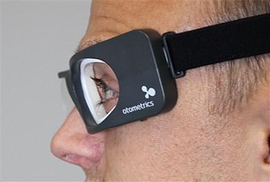
8 1 Introduction 1 Introduction Congratulations! You are now the owner of a sophisticated new ICS Impulse system developed in collaboration with Drs. Ian Curthoys, Michael Halmagyi and others at University of Sydney. To assist you in getting the most out of the ICS Impulse system, your system is delivered with a user guide, applicable quick guide(s) and training video(s). The electronic version of the user guide is provided in the application. This guide is updated each time you install a new version of the OTOsuite Vestibular. We hope you find it easy to use and that your use of the incorporated tips and information results in improved data collection accuracy as it relates to your assessment of vestibular-related disorders, test results, reporting, and patient information retrieval. 1.1 Device description ICS Impulse is a combination of hardware and software. The patient wears a pair of lightweight, tightly-fitting goggles on which is mounted a very small, very light, very fast, USB video camera and a half-silvered mirror. This transparent mirror reflects the image of the patient's eye into the camera. The eye is illuminated by a low-level infra-red light emitting diode which is not visible to the patients. A small sensor on the goggles measures the head movement. The whole goggles system is lightweight but it must be secured tightly to the head to minimize goggles slippage. The software records and displays the information obtained during what is known as a "head impulse test." The basic head impulse test starts with the tester standing behind the patient who is wearing the goggles. While the patient is asked to stare at the fixation dot placed on a projection surface in front of them, the tester rotates the patient's head horizontally through a small angle (about degrees) in a brief, abrupt and unpredictable manner, varying the direction and the velocity. The goggles collect both head and eye data. The gyroscope measures the velocity of the head movement (the stimulus). The high-speed camera captures the image of the eye. The OTOsuite Vestibular software processes the head velocity data and velocity data for eye movement (the response). Simultaneous displays of the data for head movement and for eye movement allow the clinician to determine if the response is within normal limits or not. The OTOsuite Vestibular software also records and displays the information obtained during Positional and Oculomotor tests. A Positional test is performed by moving that patient from one position to another position. In the example of Dix- Hallpike, the patient is sitting and the patient's head is turned 45 degrees to one side and then the patient is moved from the sitting position to the supine position. An Oculomotor test is performed by having the patient stare in various directions or under various environments. In the example of Gaze, the patient is sitting and the patient is asked to stare left, right, up, down or center. The Gaze test can be performed with vision or with vision denied. For both Positional and Oculomotor the goggles collect head and eye data. The accelerometer in the small sensor measures where the head is in space. That information is taken and the patient's head position or any movement during testing is displayed in the software. The high speed camera captures the image of the eye. The OTOsuite Vestibular software processes the eye velocity data (the response). The eye movement is analyzed to determine the slow phase velocities (SPV). The head data is only used during collection to display if the patient's head is moving and to guide the tester to position the patient's head appropriately for the test. This is what we refer to as "Head Position Feedback." Tests where slow phase velocity is measured display the eye position trace and slow phase velocity points in a graph. In Oculomotor there are 2 tests, VOR and Skew Deviation, that are not SPV tests. VOR (vestibular ocular reflex) allows for both visual VVOR and VOR suppression (VORS ). This test is very similar to the head impulse test but the head movement is slow (0.5 Hz) and small (10 degrees). In VVOR the patient is sitting and the examiner moves the head from side to side (like a sinusoid) while the patient stares at a fixed target. In VORS the patient is sitting and the examiner moves the head from side to side (like a sinusoid) while the patient stares at a moving dot projected from the goggles using one of the lasers. The analysis is similar to head impulse where simultaneous displays of the data for head movement and for eye movement allow the clinician to determine if the response is within normal limits or not. In Skew Deviation (also known as cover test or alternate cover test) the patient is sitting and the tester covers and uncovers an eye. The OTOsuite Vestibular software measures the eye position trace during the cover and uncover environments and displays an average eye position shift. 8 Otometrics - ICS Impulse USB
9 1 Introduction 1.2 Intended Use The ICS Impulse System is used in the assessment of the vestibular-ocular reflex (VOR) and nystagmus by measuring, recording, displaying, and analyzing eye and head movements. 1.3 Intended User Note The ICS Impulse System is intended to be used only by qualified medical personnel. This manual describes the use of the device in combination with the software in testing the vestibular system of children and adults. Readers are assumed to have prior knowledge of the medical and scientific facts underlying the procedure. For this reason, the examination methods are mentioned only to the degree that is necessary for a correct, safe application of the ICS Impulse System. You can find more information in the vhit training video or at Learn about the research behind ICS Impulse on About this manual This is your guide to using the basic functions required for navigating in OTOsuite Vestibular and the various OTOsuite Vestibular modules. This includes key features such as printing test results, handling patient and user administration, and data and test device management. Training It is recommended that you make yourself familiar with the features provided by OTOsuite Vestibular and the test device before testing a patient. Refer to page 81 for information about the training mode provided to help you learn how to perform a proper head impulse maneuver before you perform tests on a patient ICS Impulse Safety This manual contains information and cautions which must be followed to ensure the safe performance of the ICS Impulse System. Caution Local government rules and regulations, if applicable, should be followed at all times. Safety information is stated where it is relevant, and general safety aspects are described starting on page Typographical conventions The use of Warning, Caution and Note To draw your attention to information regarding safe and appropriate use of the device or software, the manual uses precautionary statements as follows: Otometrics - ICS Impulse USB 9
10 1 Introduction Warning Indicates that there is a risk of death or serious injury to the user or patient. Caution Indicates that there is a risk of injury to the user or patient or risk of damage to data or the device. Note Indicates that you should take special notice Navigating this manual Window tabs, icons and functions to select are shown in bold type, as for instance in: Click Save 10 Otometrics - ICS Impulse USB

11 2 Safety notes and warnings 2 Safety notes and warnings This manual contains information and warnings, which must be followed to ensure the safe performance of the devices and software covered by this manual. Local government rules and regulations, if applicable, should also be followed at all times. GN Otometrics ICS products are not designed to be used in conjunction with any devices not approved by GN Otometrics. Summation of combined unapproved parts could result in increased electrical leakage. All parts of the ICS Impulse system are suitable for use within the patient environment. When the ICS Impulse System is used in conjunction with a test device, make sure that all information, cautions, and warnings in the manual for the test device are followed. For safety specifics concerning test modules and test devices, see the specific manuals. 1. There are no user-serviceable parts inside the ICS Impulse System goggles. For the sake of safety and in order not to void the warranty, service and repair of electro-medical equipment should be carried out only by the equipment manufacturer or by service personnel at authorized workshops. In case of any defects, make a detailed description of the defect(s) and contact your supplier. Do not use a defective device. 2. Keep the unit away from liquids. Do not allow moisture inside the unit. Moisture inside the unit can damage the instrument and it may result in a risk of electrical shock to the user or patient. 3. Do not use the instrument in the presence of flammable agents (gases) or in an oxygen-rich environment. 4. A Class 2 Laser product is used for calibration. The laser beam projects from the front of the goggles onto a solid surface. Caution Do not look directly at the lasers. Use of controls or adjustments, or performance of procedures other than those specified herein, may result in hazardous radiation exposure. 5. It is recommended to install the unit in an environment that minimizes the amount of static electricity. For example, anti-static carpeting is recommended. 6. No parts may be eaten, burnt, or in any way used for purposes other than the applications defined in the Intended Use section of this manual. 7. The device can be disposed of as normal electronic waste, according to local regulations. 8. For safety reasons and due to effects on EMC, accessories connected to the equipment's outlet fittings must be identical to the type supplied with the system. 9. The device is disconnected from the mains by removing the USB cable. 10. Do not touch non-medical parts, such as the laptop/computer or printer and the patient at the same time. Otometrics - ICS Impulse USB 11
12 2 Safety notes and warnings 11. Exposure to electromagnetic fields can result in interference with the process of recording correct measurements. ICS Impulse System cameras and gyroscopes are sensitive to electrical disturbances. Avoid static discharges and electromagnetic fields. 12. Immediately discontinue use of the equipment if skin irritation or discomfort occurs. 13. Installation of any third party software (applications, programs, or utilities) other than those specified by GN Otometrics can compromise the safety or effectiveness of this system. 14. The ICS Impulse System needs to be installed and put into service according to the EMC information provided in this manual. Portable and mobile RF communications equipment can affect medical electrical equipment. The ICS Impulse System may be interfered with by other equipment with CISPR emission requirements. 15. The use of accessories and cables other than those specified for this device may result in increased emissions or decreased immunity of the ICS Impulse System. For more information, refer to page The ICS Impulse System should not be used adjacent to or stacked with other equipment and that if adjacent or stacked use is necessary, the equipment or system must be observed to verify normal operation in the configuration in which it will be used. 17. A small cooling fan is inside the goggles housing. In the unlikely event of the cooling fan vent being blocked, the temperature of the goggles surface in contact with the patient may rise to 42.2 C. 18. A head impulse test should not be performed on patients with a neck injury, or on patients who have been told by their physicians to limit or avoid neck movement or activity. 19. Warning notes When connecting equipment to the USB connectors, the following must be considered: Equipment must be certified to relevant EN/IEC safety standards, e.g. EN/IEC Use of connected equipment in a patient environment, see Note 1. Ensure that the medical electrical system complies with the requirements of EN or IEC (2005), 3. ed. Note 1: The ICS Impulse system is a part of a medical electrical system. When assembling a medical electrical system, the person carrying out the assembly must take into account that connecting other equipment that does not comply with the same safety requirements as the ICS Impulse system may lead to a reduction in the overall safety level of the system. The ICS Impulse system is designed to ensure compliance with requirements in EN or IEC (2005), 3. ed. when the PC, printer, etc. are placed out of reach of the patient, i.e. not closer than approx. 1.5 meters/5 ft. 12 Otometrics - ICS Impulse USB

13 3 System startup 3 System startup 1. Switch on the computer. 2. Double-click the OTOsuite Vestibular icon. Note To extend the life of the components in the goggles, it is best to close the software when not in use. If the software is left open, the fan will continue to run and cool the goggles. Logging in Note An Administrator user name and password are provided with a new installation of OTOsuite Vestibular. DO NOT delete the user name or password from the login screen until at least one new user name with password has been added. Ensure that at least one user has administrator privileges. For information on how to add new users, refer to page 199. At the login screen Note The password is case sensitive. 1. Enter your user name. 2. Enter your password and click OK Otometrics - ICS Impulse USB 13
 from the Automatic Protocol list.")
14 4 Understanding the OTOsuite Vestibular screen 4 Understanding the OTOsuite Vestibular screen Navigation panel A - General patient functions including setting up a new patient and access to the list of all patients for whom data has been collected. Open patient functions including modifying patient information and running a test(s) from the Automatic Protocol list. Collected Tests opens a list of all previously collected tests organized by test dates. Refer to page 28. B - Items grouped into a set of menus. The license in the goggles determines which test group menus (for example, Oculomotor, Head Impulse, etc.) are open the first time the OTOsuite Vestibular is started. Click to display or to hide items listed in a group menu. When the software is restarted, the groups remain as set in the previous session. Note Previously collected data for the patient is indicated by a checkmark next to each test type name. C - Button for access to the User Guide. Status bar Tabbed windows Button to hide or show Navigation panel (D), Logout button (E), current operator (F), system status (G), current date (H), and current time (I). The top level tabs corresponds to the menu group(s) from which an item in the group has been opened. In this example, the top level tab is Oculomotor (K). The corresponding subset of tabs (J) are available. The active window is the one for collecting data. The tabs for the other windows allow for the review and comparison of data results. 14 Otometrics - ICS Impulse USB
15 4 Understanding the OTOsuite Vestibular screen Startup Module The test that opens when OTOsuite Vestibular is started depends on settings in Test Options. From the Options menu in the navigation panel, click Test Options. This opens the General window that includes the setting for Automatic Protocol: Automatic Protocol set to Off - When the application is started, the test that opens is the selected Startup Module. To change to a different test, select the test from the Startup Module list. Automatic Protocol set to On - When the application is started, the test that opens is the first test in the Automatic Protocol. Starting data collection To start data collection, click the test type name in the Automatic Protocol list or, click the test name from the applicable test group in the navigation panel. Automatic Protocol - From the Test Lists group, click Automatic Protocol. In the list, click the test type name. Names grayed out in the list indicate the goggles do not include a license for that test group. Refer to page 179 for information about modifying the Automatic Protocol list. The Test Setup window is the initial window. The selections in this window match the test type selected. The setting for Torsional matches the setting in Test Options. Automatic Protocol set to On - At the end of each collection, the initial window for each new test type is the Collection window except for these conditions: ROI size is different from the previous test type (for example, Dix-Hallpike to Head Impulse or a Torsional reference frame is required because Torsional was not selected for any previous test types in the list For these exceptions, the initial window for each new test type is the Test Setup window. Automatic Protocol set to Off - Clicking the test type name is similar to clicking the test type name in the navigation panel: A single test is collected and the Analysis window displays at the end of the collection. For Vision Denied, the setting indicated in the test type name is used (instead of the setting selected in the Test Options). This setting can be changed in the Test Setup window before starting collection. Test name in navigation panel - Click the test name. Otometrics - ICS Impulse USB 15

16 4 Understanding the OTOsuite Vestibular screen In the Test Setup window, the first radio button is selected (the radio button at the far left). Vision Denied and Torsional are set according to the Test Options settings. Changes to Vision Denied and Torsional remain if new test maneuvers are selected. As each test completes, the Analysis window displays. Presentation remote The presentation remote provides an alternative method for some test functions: When using Head Position Feedback Before data collection starts, instead of clicking Center, press and hold the left button for at least 2 seconds. (The screen updates once the button is released.) To start a test Press the left button To extend the test duration After data collection starts, press and hold the left button until the tone confirms the test has been extended. (The screen updates once the button is released.) To stop a test Press the right button To set an event marker on the trace for any SPV test To mark the trace for the Skew Deviation test After data collection starts, press the left button Press the left button to indicate the eye is covered Press the left button to indicate the eye is not covered For more information about the presentation remote, refer to page 208. Resizing screen areas Note If a thick blue bar separates an area of the screen, the size of the areas can be changed. For example, to increase the width of the navigation panel, position the cursor over the blue bar until a double-headed arrow appears (A). Click the left mouse button and drag the bar to a new location. These bars separate windows vertically as shown here but can also separate windows horizontally. 16 Otometrics - ICS Impulse USB
 display in equally sized windows (normal viewing mode).")
 (2D Analysis window of Head Impulse) Otometrics - ICS")
17 4 Understanding the OTOsuite Vestibular screen Switching between viewing modes By default test results for all tests (Oculomotor, Head Impulse, and Positional ) display in equally sized windows (normal viewing mode). To enlarge one window within the group, click the small box in the top right corner of that window. Example of normal viewing mode showing small box (A) (2D Analysis window of Head Impulse) Otometrics - ICS Impulse USB 17
 (2D Analysis) Displaying eye position traces For tests that include eye position traces, the display is customizable.")

18 4 Understanding the OTOsuite Vestibular screen To return to the normal viewing mode, click the two overlapping boxes in the enlarged window. Example of normal viewing mode showing the two overlapping boxes (B) (2D Analysis) Displaying eye position traces For tests that include eye position traces, the display is customizable. Depending on the settings in Test Options, horizontal (HR) and vertical (VR) eye position traces will display in the Eye Position Traces window. There are separate settings for Collection and Analysis. These settings affect all patients. While viewing the patient data in Analysis, you can make changes that apply only to the open patient. To change what traces display, select or deselect the appropriate check box in the trace legend. The new setting remains while reanalyzing the test. When the patient file is closed or another test from the test list for that patient is selected, the display changes according to what has been selected in Test Options. Note Any change made to a setting in Test Options while the patient is open will be applied to the open patient. 18 Otometrics - ICS Impulse USB

19 5 Managing test data 5 Managing test data To view test data, open the patient. For a list of all tests collected on the open patient, click Collected Tests from the Test Lists group. The tests are organized by test dates. Refer to page Test List - single test analysis In the Test window you can view the list of tests for a patient. Clicking on the column headings allows you to reorder the tests for ease of finding a specific test. Remarks can be added to a specific test. Selecting a test To view a specific test, click on the Test window tab and then click the desired test to highlight it. To make it easier to locate a specific test, click one of the column headings. For example, click the Date & Time column heading to change the order from ascending order (older to more recent) to descending order (more recent to older). Adding remarks to a selected test For more information about test remarks, refer to page Entering test remarks 22. With the test selected, add remarks in the Remarks window, or click on the Remarks window includes editing tools. Remarks are visible in both the Test and Remarks windows. To mark a test for a specific purpose (for example, to indicate abnormal results), select the check box under the column heading marked with the unique identifier symbol:. Otometrics - ICS Impulse USB 19

20 5 Managing test data Deleting a selected test To delete a test, select the test and click Delete Test. For more information about selecting a test, refer to page Selecting a test 19. Caution If you choose to delete a selected test and click Yes at the prompt, the test data is permanently deleted. There is no possibility to retrieve the test. Deleting videos It is recommended to delete videos that are not needed in order to save disk drive space. After a video(s) has been deleted, the video data cannot be recovered. When the setting in the General options for Auto-Save Videos is set to Off, a message appears each time a new video(s) is created asking if you want to save the video(s). This option allows you to save only needed videos. If the test includes both an eye video and a room video, it is not possible to delete only the eye video or only the room video. To delete the video(s) for a selected test, click Delete Video. For more information about selecting a test, refer to page 19. Renaming a test If a test was performed using the wrong name (for example, the Caloric test selected was Left Cool but the Caloric test performed was Right Cool), the test can be renamed. Click Rename Test. Choose the new test name from the test list drop down. If the Vision Denied status is not correct then select or deselect the Vision Denied check box. Click Save. 20 Otometrics - ICS Impulse USB
, from the Videos menu, click Video Record/Playback. Click Playback.")
, the video data is permanently deleted.")
21 5 Managing test data Head Impulse videos Refer to page 107 for information about deleting videos from the Head Impulse Playback window. Video/Record Playback videos To delete the video(s), from the Videos menu, click Video Record/Playback. Click Playback. If the test is not highlighted, click the desired test to select it. Click Delete Video. Caution If you choose to delete the video for the selected test and click Yes at the prompt(s), the video data is permanently deleted. There is no possibility to retrieve the video data. Otometrics - ICS Impulse USB 21
22 5 Managing test data Entering test remarks Test remarks are added in the Remarks window that includes editing tools. Remarks window (Head Impulse ) Cut selected text Copy selected text Paste text that was cut or copied Apply bold formatting Apply italic formatting Apply underline formatting Undo actions (text entry, text formatting, etc.) starting with the most recent action and proceeding in reverse order of actions done. Reverse an undo action starting with the most recent undo and proceeding in reverse order of undo actions. Remarks added during testing are saved according to the test type and session and can be viewed and edited in the Remarks window of the selected test. Editing remarks Remarks are visible in both the Test and Remarks windows. Remarks can be edited in the Remarks window of the selected test. In the Remarks column of the Test window, text can be added and text can be deleted. Remarks in the Review Report Options window Test remarks added during analysis can be viewed, but not edited, in the Review Report Options window. Remarks can be included in the report. 22 Otometrics - ICS Impulse USB
 and in the report.")
23 5 Managing test data 5.2 Test List - combined tests analysis This test list window allows you to select which tests to include in a combined test analysis. This combined test analysis is seen in the analysis window (for example, the Hex Plot analysis of Head Impulse tests) and in the report. Selecting tests to include To add a test(s), click the button next to the test name in the Show column. To remove a test(s), click the button next to the test name in the Show column. Otometrics - ICS Impulse USB 23
24 6 Patient data entry/lists 6 Patient data entry/lists Current Patient group The Current Patient group provides information about the patient currently open. Click Edit to modify patient information Click Close to close the current patient and start a new temporary patient Note If no patient is open, a temporary patient is available. The temporary patient allows testing to start without entering patient data. The temporary patient is given a unique number based on the date and time the patient record was created (yyyymmddhhmmss where yyyy=year, mm=month, hh=hour, dd-day, mm=minute, and ss=second). Once data is saved, you will be prompted to edit the temporary patient information. For information about editing existing patient information, refer to page 25. Patients group This group allows you to create a new patient, view a list of existing patients, and review all tests available for a patient. New Patient To enter information for a new patient, click New Patient and add patient information in the form: 24 Otometrics - ICS Impulse USB

25 6 Patient data entry/lists Entries that cannot be left blank are marked with an asterisk (*). For all entries the maximum number of characters is 45. Patient ID can be numeric, alphabetical or a combination of numbers and letters. To set the gender, click the down arrow and select the appropriate entry. The date of birth format is determined by the computer setup and will display as mm/dd/yyyy or dd/mm/yyyy where mm=month, dd=day, and yyyy=year. Only numeric characters are allowed (alpha characters can not be used). Note The patient's birth date is required to determine the age-based normative data to be used for head impulse gains for that patient. Click Cancel to close the form without saving any changes. Click Save to save the data. Note The system alerts you with a message with the first occurrence of a required entry that is blank. Existing patient Note A complete description of patient list operations is provided starting on page 173. From the Patients group, click Patient List. The window that displays provides access to existing patients. Patient information is separated into columns according to the type of information such as the patient name and identification number. These columns allow searching for a particular patient by entering a few characters of the identifying information: Last Name. Otometrics - ICS Impulse USB 25

26 6 Patient data entry/lists For these columns where the search feature is available, click below the column title. A vertical cursor (A) and the button for clearing a search (B) appear. Type one or more letters or numbers to search. To clear the text entered, click. The tests collected for an existing patient are indicated by a checkmark in the appropriate test column: Oculomotor Head Impulse Positional Caloric Videos (Video Frenzel) Note The unique identifier symbol ( ) indicates the user has chosen to mark one or more tests or videos for a specific purpose (for example, it may refer to abnormal results, results to be used for a study, etc.) To select a patient, click the patient name. Buttons at the bottom of the patient list allow you to open and edit the patient file: 26 Otometrics - ICS Impulse USB

27 6 Patient data entry/lists Click Open (or double-click) to open the patient to view test results. Previously collected data for the patient is indicated by a checkmark next to each test type name. Note For a list of all tests collected on the open patient, click Collected Tests from the Test Lists group. The tests are organized by test dates. Refer to page 28. Click Edit to make changes to the existing patient information. Modify patient information in this form: Entries that cannot be left blank are marked with an asterisk (*). Otometrics - ICS Impulse USB 27

28 6 Patient data entry/lists Merging two patients The Merge window allows data from two patients to be combined into one patient. 1. From the Patients group, click Patient List. 2. Click the Merge window tab. Note It is not possible to merge a patient that is currently open. The first patient selected is identified as Patient One. The second patient selected is identified as Patient Two. 3. Select the two patients to merge. Note It is not possible to merge patients if more than two have been selected. 4. Click Merge. (The button is located in the lower right corner of the window.) 5. From either the Patient One list or the Patient Two list, choose the required Last Name, First Name, Patient ID, Gender, and Birth Date to be merged into the included in the new file created from the merged files. Note A choice must be made for each field even if there is no entry in either patient list. Data is merged into the patient created first. 6. Click OK. A message displays confirming the selected patient files were merged successfully. Collected Tests list For a list of all tests collected on the open patient, click Collected Tests from the Test Lists group. The tests are organized by test dates. 28 Otometrics - ICS Impulse USB
.")

29 6 Patient data entry/lists The window displays all data collected for that patient. The tests are organized by date and by test group. (Most recent tests are listed last). Each test group includes all test types performed within that group. Click to hide the test list for a specific date or for a specific test group. Click on a test name to display that test data. Refer to page 19 for information about test lists. Logging out To log out, click Logout (A) in the lower left corner of the screen. Otometrics - ICS Impulse USB 29
30 7 Pre-testing setup 7 Pre-testing setup 7.1 Patient preparation Warning A head impulse should not be performed on patients with a neck injury, or on patients who have been told by their physicians to limit or avoid neck movement activity. Prior to testing, provide the patient with these general recommendations: No alcohol for 48 hours before testing. Do not wear make-up around the eyes. Wear comfortable clothing. 7.2 Goggles preparation Cleaning and maintenance The ICS Impulse goggles do not require preventive maintenance. Observe the following recommended guidelines regarding cleaning and maintenance. Keep the lens cover on the camera when goggles are not in use. Keep the instrument clean and as free of dust as possible. Remove dust using a soft cloth. If required, clean the goggles housing using a damp cloth moistened with a mild detergent and water solution. Do not allow any moisture to get inside the goggles. Keep moisture away from the cooling fan. Caution Never spray or immerse the goggles components with cleaning solutions. This could contaminate the electronics and/or optics. If required, clean the mirror and/or the camera lens using the supplied cleaning cloth. The presence of fingerprints on the mirror surfaces could cause inaccurate pupil detection. If the camera or mirror is not clean, artifacts will be seen during data collection. Caution Improper cleaning of either the mirror or the camera lens may scratch the surfaces. Caution A small cooling fan is inside the goggles housing. Keep the fan blades free from any obstruction. 30 Otometrics - ICS Impulse USB


31 7 Pre-testing setup Replacing the strap 1. Remove the face cushion. 2. Use a pen to push the plastic clip down and pull out the strap clip attached to the goggles. 3. Repeat on the other side. 4. Remove the cable from both clips on the strap. 5. Obtain a new strap assembly 6. Clip the strap clips into each side of the goggles. 7. Attach the cable to both clips on the strap Replacing the face cushion Note The single-use, disposable face cushion should be replaced for each new patient. 1. To remove the face cushion, slightly flex the goggles out at the side opposite of the camera side and snap out the face cushion. Release the face cushion from the other side. 2. Properly dispose of the used face cushion. 3. Obtain a new face cushion. 4. Align the tab of the face cushion with the hole on the camera side of the goggles. 5. Ensure the face cushion is inside the nose piece. 6. Slightly flex the goggles at the opposite side, align the tab of the face cushion with the hole on this side of the goggles. 7. Double check both sides are fully inserted by pressing in at each side. Otometrics - ICS Impulse USB 31
32 7 Pre-testing setup 7.3 Goggles placement When goggles are placed properly they sit comfortably on the bridge of the nose and will not slip during the test. Caution Goggles fit is important. Improper goggles fit can result in inaccurate data collection. Goggles slippage often results in inaccurate gain values (too high). Note You can find more information in the vhit training video or at 1. Before putting the goggles on the patient ensure the goggles have a new unused face cushion. Refer to page 31. the mirror is clean. Refer to page 30. Note The single-use, disposable face cushion must be replaced for each new patient. Caution Improper cleaning may scratch the mirror surfaces. 2. If required, replace the strap. Refer to page Position the goggles on the patient s face over the bridge of the nose. 4. Bring the strap above the patient s ears and around to the back of head. 5. Tighten the strap tight enough to ensure that goggles will not shift during testing. 6. Allowing some flexibility in the cables for head movement during testing, clip the cable clip to the patient s clothing at the top of the patient's right shoulder. 7. Ensure the eyes are wide open with eyelids positioned to not interfere with pupil detection. If required, adjust the skin around the eye: Tilt the bottom of the goggles out and away from the face, pulling the skin below the eye down and repositioning the goggles to hold the skin in place. Tilt the top of the goggles out and away from the face, pulling the skin above the eye up and repositioning the goggles to hold the skin in place. 8. Visually inspect the goggles fit. 9. After placing the goggles on the patient and tightening the strap, look at how the goggles fit on the person's face. If there are gaps between the goggles and the patient's face the goggles may slip. If this is the case, consider using face cushion #2. Gaps are often seen when face cushion #1 is used on a patient with a flat nasal bridge, a trait commonly seen on persons of Asian descent. 32 Otometrics - ICS Impulse USB


33 7 Pre-testing setup Face cushion types Face cushion #1 Face cushion #2 Goggles fit Improper goggles fit Proper goggles fit Otometrics - ICS Impulse USB 33


34 7 Pre-testing setup Using the wrong face cushion can result in poor data quality Example 1 - Data collected on an Asian Korean With face cushion #1 Gain values are scattered and eye traces are larger than the head trace. This data is the result of goggles slippage. With face cushion #2 Gain values are gathered together and eye traces are reduced in amplitude. This data indicates a proper fit of the goggles. 34 Otometrics - ICS Impulse USB

35 7 Pre-testing setup Example 2 - Data collected on an Asian Filipino With face cushion #1 Gain values are gathered together and the eye traces are below the head trace. This data indicates a proper fit of the goggles. With face cushion #2 Gain values are scattered and the eye traces are noisy. Face cushion #2 was uncomfortable, making the patient blink excessively and preventing the patient from fixating on the fixation dot during the head impulse maneuver. Otometrics - ICS Impulse USB 35

36 7 Pre-testing setup 7.4 Vision-denied solution and goggles placement Preparing 1. Do not test in a room with complete darkness. While it may NOT seem intuitive, for optimal results some ambient room light is beneficial for obtaining a completely light tight test environment for the patient. 2. For patients with long eyelashes, it is advised to remove any mascara. Mascara deposited on the inside of the black window of the right eye cup (through which the pupil is tracked and the eye is recorded) adversely affects both pupil tracking and recording of the eye. Important DO NOT TOUCH THE BLACK WINDOW When handling the right-eye cup, do not touch the black window. Oils in the skin reduce the effectiveness of the anti-fog coating on the window. Fingerprints make it difficult to track the pupil. 3. Obtain a vision-denied solution (includes a cup for the right eye and a patch for the left eye). Caution The single-use, disposable vision-denied solution should be replaced for each new patient and should not be cleaned and reused. Right-eye cup Left-eye patch 4. Inform the patient that they will be in complete darkness for a short period. Assure them that, while they cannot see out, the camera in the goggles can still record their eye movement Attaching the right-eye cup 1. Remove the plastic backing from the back side of the cup. 2. Ask the patient to open their eye wide. Note It is easiest to position the cup if you and the patient are sitting at the same level instead of standing over the patient. 3. Ask the patient to stare straight ahead. You want the pupil to be in the center of the black window. 4. If the patient s eyelid droops, hold the eyelid up when placing the cup. This will assist in keeping the patient s eye wide open during testing. 5. Fold back the inside edge of the cup placing the ridge against the right side of the nose. 36 Otometrics - ICS Impulse USB


37 7 Pre-testing setup A. Ridge B. Fold back the inside edge 6. Make sure the cup is centered over the eye (not angled up or down). Important DO NOT TOUCH THE BLACK WINDOW When handling the right-eye cup, do not touch the black window. Oils in the skin reduce the effectiveness of the anti-fog coating on the window. Fingerprints make it difficult to track the pupil. 7. Press gently around the edges to make sure that a seal has formed all the way around. Make sure that the cup is light tight Attaching the left-eye patch 1. Remove the plastic backing from the back side of the patch. 2. Ask the patient to close their eye. 3. Position the patch with the wider side toward the nose. Make sure the patch is centered over the eye (not angled up or down). 4. Press gently around the edges to make sure that a seal has formed all the way around. Make sure that the patch is light tight Verify light tightness 1. Give the patient a couple of minutes for the eyes to adjust. 2. Ask the patient if they can see any visible light. Do NOT have the patient look directly at a light bulb (spot light, halogen, incandescent). 3. With the vision-denied cup and patch attached well, and the patient unable to detect light, proceed with placing the goggles on the patient Goggles placement over the vision-denied solution Note Before placing the goggles over the vision-denied solution, make sure the goggles have a new unused face cushion. 1. In the OTOsuite Vestibular software, open a test from either the Oculomotor or Positional test group, or, from the Videos test group, open Video Record/Playback. 2. Position the goggles on the patient with the cup centered inside the goggles. Otometrics - ICS Impulse USB 37
.")

38 7 Pre-testing setup 3. Tighten the strap so that the goggles stay on the patient during the testing but the goggles do NOT have to be as tight as needed for head impulse testing. Note The strap only has to be tight enough for the goggles to stay on during testing (spontaneous nystagmus, gaze, positional). You do not want to tighten the strap as tight as you would for head impulse testing. A strap that is too tight pushes the vision-denied solution into the face causing discomfort which makes recording of eye movement more difficult. 4. Check that the eye is centered inside the window of the cup. Good Position Poor Position A. Not centered vertically: Should see more of the eyelid above the eye. B. Not centered vertically: Should see less of the area below the eye. C. Not centered horizontally: Inner edge of cup is not close enough to the nose. Notice the corner of the eye at the edge of the cup. 38 Otometrics - ICS Impulse USB
39 7 Pre-testing setup Removing the vision-denied cup and patch Note Slowly removing the vision-denied cup and patch is much more comfortable than quickly removing them. If needed, a small amount of water placed between the patient's skin and the cup and/or patch makes removing them easier. 1. Ask the patient to close their eyes. 2. SLOWLY pull the cup and patch off of the patient s face. Otometrics - ICS Impulse USB 39
40 8 Oculomotor 8 Oculomotor 8.1 Test environment The environment can vary but must allow you to position the patient at least one meter from the wall (or other solid surface that can be used as a projection surface).athis position will be utilized for calibration and for Saccade and VOR testing. For Gaze (Gaze and Spontaneous) and Skew Deviation testing, the patient only needs to be positioned comfortably either sitting or in a supine position with the head at a 30 angle. For Calibration and Test Purposes: Note The patient should be seated in a chair that is stationary and does not swivel. 1. Choose a wall that allows you to position the patient at least one meter in front of the fixation dot. 2. Apply one of the fixation dots supplied with the system to the wall in a location that allows you to position the patient directly in front of the fixation dot. 8.2 Video recording eye movement during testing Note Record must be checked in order to be able to play back the collected data. The Video window displays the image of the eye. The Record (A) is checked by default. The video recording of the eye and data collection start at the same time. 8.3 Pupil detection For instructions on proper placement of the goggles only, refer to page 32. For instructions on proper placement of the vision-denied solution, refer to page Otometrics - ICS Impulse USB

41 8 Oculomotor 1. Select the test: Gaze, VOR, Skew Deviation, or Saccade. 2. Select the test type. For example, there are two test types for the Gaze test: Gaze and Spontaneous. Note Vision Denied should not be checked when performing calibration. 3. If using the vision-denied solution, select the check box Vision Denied. Note Without the license, it is not possible to determine if Torsional nystagmus is present during testing. When purchased, the license provides an eye position trace and SPV graph. 4. To collect Torsional data, select the check box Torsional. (To have Torsional selected by default, in Test Options select the option for this test type in the applicable window for this test group.) Refer to page 251 to understand the increase in video file size when Torsional is selected. 5. Select the test maneuver (A). For example, there are seven maneuvers for the Gaze test: Center, Left, Rebound Left, Right, Rebound Right, Up, and Down. Note Selecting either Vision Denied or Torsional changes the collected frame rate to 60 fps (frames per second).selecting Vision Denied changes the collected frame rate to 60 fps (frames per second). This rate allows the camera shutter to stay open longer (increases the light exposure) which results in a better quality image. When Vision Denied is selected, a check mark is placed in the vision denied column in the test list. 6. If collecting Torsional data A. Instruct the patient to stare straight ahead and to keep theirs eye wide open. B. Click Capture. The Torsional reference frame displays in the bottom right corner of the Test Setup window. The reference frame is compared with the collected data to determine if torsional eye movement is present. The reference frame can be used for all subsequent SPV tests. If the quality is poor, re-instruct the patient and click Capture again. Otometrics - ICS Impulse USB 41
42 8 Oculomotor Good Quality Poor Quality 7. Position the patient. Refer to page Position the ROI (Region of Interest) around the pupil: click on the green box and drag to center it on the pupil, or click on the pupil to center the pupil inside the green box. 9. In the Video window, choose the type of image displayed: Grayscale Image (A) or Pupil Location (B). Note The choice of Grayscale Image or Pupil Location is only used for setting the pupil detection. Eye video is always recorded in grayscale. 10. If the pupil was not automatically detected, select Auto-Threshold. The system centers the cross-hair on the pupil. 11. Ask the patient to stare at the fixation dot. Assess pupil tracking by observing the cross-hair. If the cross-hair fails to track the pupil (jumps around and does not stay centered on the pupil), use the + or button of the threshold slider to adjust. Pupil detection ensures that the system tracks the pupil properly during calibration and when collecting data. 42 Otometrics - ICS Impulse USB
43 8 Oculomotor Note Make additional adjustments to remove any white areas outside the white circular image of the pupil. 12. Select OK to accept the ROI Position. 13. If calibration has not been previously performed, continue at page Calibration Caution During this procedure both lasers will turn on. Do not look directly at the lasers. Use of controls or adjustments, or performance of procedures other than those specified herein, may result in hazardous radiation exposure. 1. Click Lasers On to turn on both lasers. 2. Ask the patient to position the left and right dots equidistant on each side of the fixation dot. 3. Ask the patient to look at the left dot, then at the right dot. In the Video window, check that the cross-hair continues to track the pupil. Otometrics - ICS Impulse USB 43
44 8 Oculomotor Note Use the Real Time Traces (X-axis in seconds) window to monitor head and eye data. By observing the orange head trace and the green eye trace, you can tell if the patient is moving their head or eyes (instead of staring at the fixation dot), blinking excessively, or not following instructions being given (not cooperating). 4. If the cross-hair fails to track the pupil (jumps around and does not stay centered on the pupil), use the + or button of the threshold slider to adjust. In the calibration procedure, the patient is asked to switch their gaze between the two dots that appear when the lasers are on. As the patient s gaze switches, the system tracks the movement of the pupil. Note When a patient cannot be calibrated (for example the vision is so poor that the patient cannot see the fixation dot or laser beams dots), click Default to use the calibration default value ( = 21). Make sure the patient is looking straight ahead at the fixation dot before you click Default. The eye movement between the two laser beam dots is measured and calibrated against the known values the laser beam dots projected from the goggles. The calibration values relate to the pixel location that equates to 7.5 degrees left and right of center. The difference between the left and right equates to the number of pixels for a 15 degree movement of the eye. These values are used to analyze eye movement during head impulse testing. 5. Click Run. 6. Ask the patient to face the fixation dot and hold their head still. 7. Ask the patient to follow the laser beam dot. Note The calibration values are automatically saved. The stored calibration value can be used for all tests. There is no need to recalibrate between tests unless the goggles have moved. If you exit out of the patient s file and reopen, calibration will need to be performed again. Calibration check 1. Ask the patient to stare at the fixation dot and move the head side to side through a small angle (about 10 degrees). 2. Check that the eye and head velocities match. 44 Otometrics - ICS Impulse USB
45 8 Oculomotor Good calibration - Eye and head velocities match (Examples of poor calibration show a calibration performed in Head Impulse) Poor calibration - Eye velocity is too low Poor calibration - Eye velocity is too high 3. If the eye and head velocities do not match, you need to recalibrate or review the patient s history. Otometrics - ICS Impulse USB 45
46 8 Oculomotor Note If the patient has to make catch-up saccades during low frequency head rotations, this can indicate either vestibular loss, or cerebellar dysfunction, or both. When test results include catch-up saccades during low frequency head rotations, it is recommended that the Head Impulse test results be interpreted with caution. Data NOT within normal limits could be related to a peripheral and/or central disorder. Use the VOR tests to assess a patient with catch-up saccades during calibration check. 4. Once the calibration has been checked and you are satisfied with the result, click Accept. The Collection window opens and the software is ready to begin collecting head impulse data. Caution Once calibration has been performed, it is recommended not to reposition the goggles on the patient s head. 46 Otometrics - ICS Impulse USB
47 8 Oculomotor 8.5 Optimizing collection This application provides these features to ensure good data collection: External Monitor You have the option to display a larger image of the eye on an external monitor. If an external monitor is connected to the computer, position the monitor where you can easily see the eye video. To display the eye video on the computer monitor as well as on an external monitor, click. The external monitor displays the real time SPV value for SPV tests and Elapsed Time. For Gaze tests, the Gaze Position changes according to the degree of eye movement from the center during testing. For Saccade tests, the Accepted and Collected number of saccades display during testing. During playback the external monitor displays the eye video. Head Position Feedback or Synchronized Room Video will also display if set in Test Options. Note The external monitor is not supported for head impulse testing. Head Position Feedback For SPV tests, the Head Position Feedback option is the default setting. When set to this option, a reference graphic of the patient's head position in real time displays on the computer monitor. For information about setting this option, refer to page Gaze tests In these tests, the goggles collect horizontal and vertical eye position data. The high speed camera captures the image of the eye.the OTOsuite Vestibular software processes the eye position data and calculates the slow-phase velocity (SPV). Gaze tests provide the ability to assess for gaze and spontaneous nystagmus. The purpose of these two test types is to identify nystagmus that is evoked by having the patient stare at certain positions. The patient is typically in a sitting position or in the caloric position (head inclined 30 ). The position of the eye is calculated and displays as the Gaze Position. Gaze This test type assesses the patient s eye movement when the eyes are fixated in different directions (Left, Right, Up, Down and Center). There are two additional test conditions (Rebound Left and Rebound Right). These conditions assess rebound nystagmus. The test is started with the patient looking leftward or rightward. Then data is collected as the patient returns their gaze to center. The person assessing the patient will provide the stimulus at which the patient is to stare. This stimulus can be the tester s finger, an implement (for example, the tip of pen or bobby pin) or the laser light presented on a wall from a presentation remote. Or, as in the case of vision-denied testing, the patient can be verbally instructed to look into the chosen direction. According to the ANSI standard, the eyes should be recorded for a minimum of 10 seconds with the eyes positioned at 30 from center, right and left as well as 25 from center for up and down. The gaze position provides the degrees to which the patient is staring from center. In order to assess for alternating or direction changing nystagmus the eyes should be recorded for more than 2 minutes. Please be aware that having the patient look further than the degrees stated above can result in end-point nystagmus which is not diagnostically relevant. The Gaze test may be performed with vision or with vision denied. Spontaneous This test type assesses the patient s eye movement when the eyes are in the primary position looking straight ahead without any visual stimulus. According to the ANSI standard, the eyes should be recorded for a minimum of 20 seconds. Otometrics - ICS Impulse USB 47

48 8 Oculomotor The patient or patient's head may be in various conditions such as sitting, supine, chin to chest or head extended backward. The Spontaneous test may be performed with vision or with vision denied. Other This test type allows you to define the test you want to collect and allows you to assess the patient s eye movement. 8.7 Collecting Gaze data For information about settings available in Test Options when collecting data, refer to page 178. Note The temporary patient is available to allow testing to start without entering any patient data. Refer to page 24 to create a new patient or open an existing patient. When collecting data, you can monitor head movement using the Head Position Feedback display or Synchronized Room Video. You can also choose to not use either. (The default display is set in Test Options.) Note If using Synchronized Room Video, you may need to adjust the camera position to ensure the entire head of the patient is seen in the video during data collection. If recording audio, it is important to position the camera to minimize the level of ambient noise. 1. Position the patient's head. 2. Set the center reference point: A. Instruct the patient. B. Click Laser On (A). C. Ask the patient to stare at the laser dot that appears on the wall. Making sure the head is centered, click Center or press and hold the left button on the presentation remote for at least 2 seconds. (The screen updates once the button is released.) 3. Ask the patient to look straight ahead at your finger. Verify the gaze position displayed is Proceed according to the selection: Test condition - all except Rebound Left Ask the patient to follow the stimulus to the gaze position desired: To begin data collection, click Start or press 48 Otometrics - ICS Impulse USB

49 8 Oculomotor the left button on the presentation remote. Test condition - only Rebound Left Ask the patient to follow the stimulus to the left or right. To begin data collection, click Start or press the left button on the presentation remote. After starting collection, ask the patient to move their gaze back to the center gaze position. To continue collecting data beyond the maximum duration time set in the test options, click Extend or press and hold the left button on the presentation remote. A tone confirms the test has been extended. To stop collection, click Stop or press the right button on the presentation remote. Eye Position Traces Depending on the settings in Test Options, horizontal (HR) and vertical (VR) eye position traces will display in the Eye Position Traces window. To insert an event marker ( ) on the trace during collection, use one of these methods: Press the left button on the presentation remote. Click Event. The event markers are inserted below the trace. SPV value The real time SPV (slow-phase velocity) value (A) is an estimated value calculated according to the amount of variability around the SPV estimate. The value is displayed in either green or orange in the upper right area of the window. Green: When the variability is low, there is a high probability that the value is reliable. Orange: When the variability is high, there is less probability that the value is reliable. Note SPV values displayed in orange should be considered less reliable but not inaccurate. Gaze Position value The Gaze Position position value (B) is the degree of eye movement from center. The position displays before starting data collection and while data is collected. Leftward eye movement is a negative value. Rightward eye movement is a positive value. Note You can find more information in the Oculomotor training video or at Displayed in the Collection window are: A. Test Type name of test for which data has been collected (The name includes the test direction and the test conditions.) Otometrics - ICS Impulse USB 49

50 8 Oculomotor B. Elapsed Time duration of the test C. Frame Rate frequency of data acquisition in frames per second (fps) D. Calibration the distance in pixels between the right and left eye positions measured during calibration The system automatically stops when the maximum test duration is reached. (The maximum test duration is set in Test Options.) To continue collecting data beyond the maximum duration time set in the test options, click Extend or press and hold the left button on the presentation remote. A tone confirms the test has been extended. To stop collection, click Stop or press the right button on the presentation remote. To stop the test early, click Stop or press the right button on the presentation remote. Data will be saved. To stop the test early, without saving data, click Cancel. The data is analyzed and displayed in the Analysis window. 8.8 Gaze data analysis To view a specific test, click on the Test window tab and then click the desired test to highlight it. For more information about selecting a test, refer to page Analysis window Analysis of the test results can be displayed in the normal viewing mode or in the enlarged mode. Refer to page 17. Eye Position Traces Depending on the settings in Test Options, horizontal (HR) and vertical (VR) eye position traces will display in the Eye Position Traces window. To change what traces display, select or deselect the appropriate check box in the trace legend. The new setting remains while reanalyzing the test. When the patient file is closed or another test from the test list for that patient is selected, the display changes according to what has been selected in Test Options. Note Any change made to a setting in Test Options while the patient is open will be applied to the open patient. The traces are centered around the cursor. The report prints the part of the trace seen in the Traces window centered around the cursor. 50 Otometrics - ICS Impulse USB
 and vertical right (VR ) traces.")

51 8 Oculomotor Slow Phase Velocity graph The purpose of this graph is to provide a record of the strength of the nystagmus. This graph displays the individual nystagmus points identified by the SPV algorithm for the horizontal right (HR ) and vertical right (VR ) traces. The SPV Peak ( /s) is indicated in the graph by a square. To select a particular point, click on it or use the left/right arrow keys to move between points (between beats). The SPV window (B). Note Select TR to display the eye position trace and the SPV graph for Torsional. If the algorithm did not pick a peak, manually set the peak for that trace. To choose when analysis begins, refer to the description of the Reanalysis window on page 52. Refer to page 242 for information about how the Peak ( /s) is determined. Analysis Details - Info The test parameters are listed: Test Type name of test for which data has been collected Otometrics - ICS Impulse USB 51
52 8 Oculomotor Operator the person who was logged into OTOSuite Vestibular software when the data was collected Calibration the distance in pixels between the right and left eye positions measured during calibration Test Time date and time data collection was started Elapsed Time duration of the test Analysis Begin Time time at which analysis began SPV values Point ( /s) the slow phase velocity of the selected point (selected beat) Peak ( /s) where the slow phase velocity peak is set Refer to page 242 for information about how the Peak ( /s) is determined. Avg ( /s) average velocity of all data analyzed Min ( /s) minimum velocity of all data analyzed Max ( /s) maximum velocity of all data analyzed Analysis Details - Remarks Remarks regarding the test can be entered before, during, and after testing. To add or modify remarks, click the Remarks window tab. For information about the editing tools, refer to page 22. Note Text previously added in the Test window appears in the Remarks window. Analysis Details - Reanalysis Analysis Begin Time - All Traces To exclude data in a trace from the analysis: 1. Move the black cursor to the new begin time in the Eye Position Traces window. 2. In the Analysis Details window, click the Reanalysis window tab. 3. To reanalyze, click Reanalyze from Cursor - analyzes all traces with the begin time set to the next full second following the cursor position Reanalyze Full Trace - analyzes all traces from the beginning 52 Otometrics - ICS Impulse USB
53 8 Oculomotor Note The begin time is displayed in the Info window. SPV Graph Note Without the license, it is not possible to determine if Torsional nystagmus is present during testing. When purchased, the license provides an eye position trace and SPV graph. Select the trace to modify by choosing HR, VR, or TR. Point ( /s) Delete - excludes the selected point from the analysis and on the report Restore - restores all points that were manually deleted Peak ( /s) Select - sets a new peak according to the cursor position Restore - restores the peak to the location determined by the algorithm Refer to page 242 for information about how the Peak ( /s) is determined Playback of data collection The eye position traces and the eye video can be played back synchronously with the head position feedback or the room video recorded during testing. Video Playback buttons and selections Play Pause Stop Play from Cursor Speed Starts the synchronized playback. Pauses the synchronized playback. Stops the synchronized playback. Select to start the playback at the position of the cursor. If not selected, playback starts at the beginning of the trace. Note Before setting the playback speed, check the recorded frame rate (fps) stated below the eye video. Normal - eye video recorded at 30 frames per second can only be played back at normal speed. Slow - eye video recorded at 60 frames per second can be played back at normal or slow speed. Slower - eye video recorded at > 60 frames per second can be played back at normal, slow, or slower speed. Otometrics - ICS Impulse USB 53

, click in the column in the Test List.")
54 8 Oculomotor Gaze Graph For data collected prior to version 4.0, click on the Analysis tab. In the Analysis Details window, click on the Reanalysis tab. Click Reanalyze from Cursor or Reanalyze Full Trace to reanalyze the data. Click on the Gaze Graph tab and select the test from the Test List to view the data in this window. All five gaze tests must be reanalyzed separately in order to populate the data in the Gaze Graph Analysis window. Gaze test conditions Center, Left, Right, Up, and Down can be reviewed in the Gaze Graph Analysis window. To remove or add a test(s), click in the column in the Test List. Only one test for each test condition can be selected to display. Eye Position Traces Horizontal (HR) and vertical (VR) eye position traces for the selected tests display in the Eye Position Traces window. The traces are centered around the cursor. To view an entire trace, click the Analysis tab. Gaze Graph Analysis This graph displays results of the automatic analysis. 54 Otometrics - ICS Impulse USB
55 8 Oculomotor The relative position of the eye is determined for each test condition. Each test condition is represented by a box in the graph: rightward gaze in the left box (based on patient looking at tester), leftward gaze in the right box, upward gaze in the top box, center gaze in the center box, and downward gaze in the bottom box. The nystagmus for each test condition is assessed for direction, velocity, and amplitude. The arrows in the diagram show the direction (points in direction based on patient looking at tester), amplitude intensity (based on the thickness of the bar of the arrow) and, velocity intensity (based on thickness of the tail of the arrow) of the nystagmus. The intensity cutoffs for the arrow are set in Test Options. A circle indicates no nystagmus detected. The following values are provided for each Gaze test condition selected: Direction : direction in which the nystagmus is beating SPV x ( /s) : the average slow phase velocity of the nystagmus in degrees per second Amplitude ( ) : the average amplitude of the nystagmus in degrees 8.9 VOR tests In these tests, the goggles collect both head and eye data. The gyroscope measures the velocity of the head movement (the stimulus). The high speed camera captures the image of the eye. The OTOsuite Vestibular software processes the eye and head velocity data (the response). Simultaneous displays of the data for head movement and for eye movement allow the clinician to determine if the response is within normal limits or not. The VOR tests provide the ability to assess the vestibulo-ocular reflex (VOR) with visual enhancement and without visual enhancement. The purpose of these two test types is to identify if catch-up saccades are present in either test condition. The patient is in a sitting position 1 meter from the wall where the fixation target is fixed and the suppression target is projected. VVOR (Visual VOR) This test type assesses the patient s vestibulo-ocular reflex with visual enhancement. The patient is asked to stare at the fixed fixation dot on the wall. The person assessing the patient slowly moves the patient s head at about 0.5 Hz and with an amplitude of 10 in the horizontal plane or in the vertical plane. The patient should maintain fixation on the dot for the duration of the test. VORS (VOR Suppression) This test type assesses the patient s vestibulo-ocular reflex without visual enhancement. The patient is asked to stare at the laser dot on the wall. This laser dot will move with the head. The person assessing the patient slowly moves the patient s head at about 0.5 Hz with amplitude of 10 in the horizontal plane or in the vertical plane. The patient should continue to follow the laser dot for the duration of the test. This test may be performed in a darkened room Collecting VOR data For information about settings available in Test Options when collecting data, refer to page 178. Note The temporary patient is available to allow testing to start without entering any patient data. Refer to page 24 to create a new patient or open an existing patient. When collecting data, the Synchronized Room Video is available. (Due to the faster frame rate acquisition of the camera, the Head Position Feedback is not available for VOR tests.) Otometrics - ICS Impulse USB 55
56 8 Oculomotor If using Synchronized Room Video, you may need to adjust the camera position to ensure the entire head of the patient is seen in the video during data collection. If recording audio, it is important to position the camera to minimize the level of ambient noise. 1. Instruct the patient. (For example, tell them to keep their eyes open and stare at the fixation dot.) 2. To begin data collection, click Start or press the left button on the presentation remote. To continue collecting data beyond the maximum duration time set in the test options, click Extend or press and hold the left button on the presentation remote. A tone confirms the test has been extended. To stop collection, click Stop or press the right button on the presentation remote. Trace recordings display in the Real Time Traces (X-axis in seconds) window. This display includes the eye and head velocities. To insert an event marker ( Press the left button on the presentation remote. Click Event. The event markers are inserted below the trace. ) on the trace during collection, use one of these methods: Note You can find more information in the Oculomotor training video or at Displayed in the Collection window are: A. Test Type name of test for which data has been collected (The name includes the test direction and the test conditions.) B. Elapsed Time duration of the test C. Frame Rate frequency of data acquisition in frames per second (fps) D. Calibration the distance in pixels between the right and left eye positions measured during calibration 56 Otometrics - ICS Impulse USB
 To continue collecting data beyond the maximum duration time set in the test options, click Extend or press and hold the left button on the presentation remote.")
57 8 Oculomotor The system automatically stops when the maximum test duration is reached. (The maximum test duration is set in Test Options.) To continue collecting data beyond the maximum duration time set in the test options, click Extend or press and hold the left button on the presentation remote. A tone confirms the test has been extended. To stop collection, click Stop or press the right button on the presentation remote. To stop the test early, click Stop or press the right button on the presentation remote. Data will be saved. To stop the test early, without saving data, click Cancel. The data is analyzed and displayed in the Analysis window VOR data analysis To view a specific test, click on the Test window tab and then click the desired test to highlight it. For more information about selecting a test, refer to page Analysis Window Analysis of the test results can be displayed in the normal viewing mode or in the enlarged mode. Refer to page 17. Real Time Traces (X-axis in seconds) Traces in the graph display the eye and head velocity during data collection. To change what traces display, select or deselect the appropriate check box in the trace legend. The new setting remains while reanalyzing the test. When the patient file is closed or another test from the test list for that patient is selected, the display changes according to what has been selected in Test Options. Otometrics - ICS Impulse USB 57


58 8 Oculomotor To view an entire trace use the scroll bar below the trace.the report prints the part of the trace seen in the Traces window centered around the cursor. Analysis Details The test parameters are listed: Test Type name of test for which data has been collected Operator the person who was logged into OTOSuite Vestibular software when the data was collected Calibration the distance in pixels between the right and left eye positions measured during calibration Test Time date and time data collection was started Elapsed Time duration of the test Analysis Details - Remarks Remarks regarding the test can be entered before, during, and after testing. To add or modify remarks, click the Remarks window tab. For information about the editing tools, refer to page 22. Note Text previously added in the Test window appears in the Remarks window Playback of data collection The eye and head velocity traces and the eye video can be played back synchronously with the room video. 58 Otometrics - ICS Impulse USB
59 8 Oculomotor Video Playback buttons and selections Play Pause Stop Play from Cursor Speed Starts the synchronized playback. Pauses the synchronized playback. Stops the synchronized playback. Select to start the playback at the position of the cursor. If not selected, playback starts at the beginning of the trace. Note Before setting the playback speed, check the recorded frame rate (fps) stated below the eye video. Normal - eye video recorded at 30 frames per second can only be played back at normal speed. Slow - eye video recorded at 60 frames per second can be played back at normal or slow speed. Slower - eye video recorded at > 60 frames per second can be played back at normal, slow, or slower speed Skew Deviation test In this test, the goggles collect eye data. The high speed camera captures the image of the eye. The OTOsuite Vestibular software processes the eye position data and calculates the degrees of eye deviation. This test type provides the ability to assess the patient s ocular alignment when the patient is in different positions (Sitting or Supine) using an alternate cover test. The purpose of this test is to identify if ocular misalignment occurs as a result of covering and uncovering one of the eyes. The patient is in a sitting or supine position. The patient s eye movement is recorded with the eyes in the primary position as first the right eye is covered and then moving the cover from one eye to the other Collecting Skew Deviation data For information about settings available in Test Options when collecting data, refer to page 178. Note The temporary patient is available to allow testing to start without entering any patient data. Refer to page 24 to create a new patient or open an existing patient. When collecting data, the Synchronized Room Video is available. (The Head Position Feedback is not available for this test because the head is stationary.) If using Synchronized Room Video, you may need to adjust the camera position to ensure the entire head of the patient is seen in the video during data collection. If recording audio, it is important to position the camera to minimize the level of ambient noise. 1. Instruct the patient. (For example, tell them to keep the eyes open and stare straight ahead.) Otometrics - ICS Impulse USB 59

60 8 Oculomotor 2. To begin data collection, click Start or press the left button on the presentation remote. To continue collecting data beyond the maximum duration time set in the test options, click Extend or press and hold the left button on the presentation remote. A tone confirms the test has been extended. To stop collection, click Stop or press the right button on the presentation remote. Depending on the settings in Test Options, horizontal (HR) and vertical (VR) eye position traces will display in the Eye Position Traces window. 3. During data collection, in order for the average eye position shift to be calculated correctly, manually indicate when the right eye is covered ( ) or uncovered ( ). Use one of these methods: Press the left button on the presentation remote. This button toggles between inserting and. Click Cover/Uncover. The icons are inserted below the trace. Note You can find more information in the Oculomotor training video or at Displayed in the Collection window are: A. Test Type name of test for which data has been collected (The name includes the test direction and the test conditions.) B. Elapsed Time duration of the test C. Frame Rate frequency of data acquisition in frames per second (fps) D. Calibration the distance in pixels between the right and left eye positions measured during calibration 60 Otometrics - ICS Impulse USB
61 8 Oculomotor The system automatically stops when the maximum test duration is reached. (The maximum test duration is set in Test Options.) To continue collecting data beyond the maximum duration time set in the test options, click Extend or press and hold the left button on the presentation remote. A tone confirms the test has been extended. To stop collection, click Stop or press the right button on the presentation remote. To stop the test early, click Stop or press the right button on the presentation remote. Data will be saved. To stop the test early, without saving data, click Cancel. The data is analyzed and displayed in the Analysis window Skew Deviation data analysis To view a specific test, click on the Test window tab and then click the desired test to highlight it. For more information about selecting a test, refer to page Analysis window Analysis of the test results can be displayed in the normal viewing mode or in the enlarged mode. Refer to page 17. Eye Position Traces Depending on the settings in Test Options, horizontal (HR) and vertical (VR) eye position traces will display in the Eye Position Traces window. To change what traces display, select or deselect the appropriate check box in the trace legend. The new setting remains while reanalyzing the test. When the patient file is closed or another test from the test list for that patient is selected, the display changes according to what has been selected in Test Options. Note Any change made to a setting in Test Options while the patient is open will be applied to the open patient. The traces are centered around the cursor. The report prints the part of the trace seen in the Traces window centered around the cursor. Otometrics - ICS Impulse USB 61

62 8 Oculomotor Analysis Details -Info The test parameters are listed: Test Type name of test for which data has been collected Operator the person who was logged into OTOSuite Vestibular software when the data was collected Calibration the distance in pixels between the right and left eye positions measured during calibration Test Time date and time data collection was started Elapsed Time duration of the test Avg Eye Position Shift ( ) the average eye position deviation (for the horizontal and vertical traces) when the condition changes between the eye being covered and uncovered. Analysis Details - Remarks Remarks regarding the test can be entered before, during, and after testing. To add or modify remarks, click the Remarks window tab. For information about the editing tools, refer to page 22. Note Text previously added in the Test window appears in the Remarks window Playback of data collection The eye position traces and the eye video can be played back synchronously with the room video. Video Playback buttons and selections Play Pause Stop Starts the synchronized playback. Pauses the synchronized playback. Stops the synchronized playback. 62 Otometrics - ICS Impulse USB
63 8 Oculomotor Video Playback buttons and selections Play from Cursor Speed Select to start the playback at the position of the cursor. If not selected, playback starts at the beginning of the trace. Note Before setting the playback speed, check the recorded frame rate (fps) stated below the eye video. Normal - eye video recorded at 30 frames per second can only be played back at normal speed. Slow - eye video recorded at 60 frames per second can be played back at normal or slow speed. Slower - eye video recorded at > 60 frames per second can be played back at normal, slow, or slower speed Saccade tests In the Saccade test, the goggles project visual horizontal saccade stimuli (laser dots that move back and forth) onto a surface and collect horizontal eye position data. The high-speed camera captures the image of the eye. The OTOsuite Vestibular software processes the eye position data and compares it to the stimuli. The Saccade test provides the ability to assess the visual and oculomotor system when presented with rapid goal-directed targets. The purpose of the test is to identify if abnormal eye movements are present when the patient follows the horizontal saccade stimuli. The patient is in a sitting position at least 1 meter from the stimuli. The eye movement is compared to the stimulus. Amplitude, velocity, accuracy and latency are measured: Amplitude ( ) measures the size of the jump between initial position and first stop of the eye movement of more than 75 ms. Values are positive for rightward eye movements and negative for leftward eye movements. Peak Velocity ( /s) measures the speed of the eye movement and is the maximum velocity reached in a saccadic eye movement over an ms period. Values are positive for rightward eye movements and negative for leftward eye movements. Accuracy (%) measures the size of the eye movement excursion divided by the target excursion. Latency (ms) measures the reaction time or time between target movement and the first eye movement of more than a 108 /s. The algorithm rejects as artifacts eye movements that occur too early (150 ms before through 75 ms after target movement), too late (500 ms after target movement) or in the wrong direction. Saccade This test type assesses the patient s eye movement when the eyes are following a saccade stimuli. The stimuli are projected from the goggles onto a surface. Each eye position is held for one second. The 3-laser saccade test presents 3 stimuli randomized in amplitude and direction from 7.5 to 15 horizontally leftward and rightward. The Saccade test is be performed with vision Collecting Saccade data For information about settings available in Test Options when collecting data, refer to page 178. Otometrics - ICS Impulse USB 63

64 8 Oculomotor Note The temporary patient is available to allow testing to start without entering any patient data. Refer to page 24 to create a new patient or open an existing patient. When collecting data, you can monitor head movement using the Head Position Feedback display or Synchronized Room Video. You can also choose to not use either. (The default display is set in Test Options.) 1. This step applies only when monitoring the head movement during collection: If using Synchronized Room Video, you may need to adjust the camera position to ensure the entire head of the patient is seen in the video during data collection. If recording audio, it is important to position the camera to minimize the level of ambient noise. If using Head Position Feedback, position the patient's head before starting to collect data. Ensure that the patient's head is not moving and that it is perfectly centered. Set the center reference point: A. Instruct the patient.(for example, tell them to keep their eyes open.) B. Click Center On (A). C. Ask the patient to stare at the laser dot that appears on the wall. Making sure the head is centered, click Center or press and hold the left button on the presentation remote for at least 2 seconds. (The screen updates once the button is released.) Note Although not required, the best way to explain the task to the patient is to turn on the saccade stimuli and allow the patient to practice following the stimuli. 2. Click Stimuli On (B) to display the saccade stimuli. 3. Instruct the patient. (For example, tell them to keep the eyes open and head still, do not anticipate where the target will move, and continue to follow the target on the wall.) 4. To begin data collection, click Start or press the left button on the presentation remote. To continue collecting data beyond the maximum duration time set in the test options, click Extend or press and hold the left button on the presentation remote. A tone confirms the test has been extended. To stop collection, click Stop or press the right button on the presentation remote. Stimulus and Horizontal (HR window. The Accepted (A) and Collected (B) number of saccades displays in the upper right area of the window. 64 Otometrics - ICS Impulse USB

 B. Elapsed Time duration of the test C.")
65 8 Oculomotor Note If saccades are not being accepted, recalibrate and restart the test. For young children or older adults who can not keep their head still, it may be necessary to hold their head still during calibration and during the data collection. Note You can find more information in the Oculomotor training video or at Displayed in the Collection window are: A. Test Type name of test for which data has been collected (The name includes the test direction and the test conditions.) B. Elapsed Time duration of the test C. Frame Rate frequency of data acquisition in frames per second (fps) D. Calibration the distance in pixels between the right and left eye positions measured during calibration The system automatically stops when the maximum test duration is reached. (The maximum test duration is set in Test Options.) To continue collecting data beyond the maximum duration time set in the test options, click Extend or press and hold the left button on the presentation remote. A tone confirms the test has been extended. To stop collection, click Stop or press the right button on the presentation remote. To stop the test early, click Stop or press the right button on the presentation remote. Data will be saved. To stop the test early, without saving data, click Cancel. The data is analyzed and displayed in the Analysis window. Otometrics - ICS Impulse USB 65


66 8 Oculomotor 8.17 Saccade data analysis To view a specific test, click on the Test window tab and then click the desired test to highlight it. For more information about selecting a test, refer to page Analysis window Analysis of the test results can be displayed in the normal viewing mode or in the enlarged mode. Refer to page 17. Eye Position Traces Stimulus and Horizontal (HR) eye position traces display in the Eye Position Traces window. The traces are displayed centered in the middle of the window. To view an entire trace use the scroll bar below the trace. The report prints the part of the trace seen in the Traces window centered around the cursor. Saccade Graphs The purpose of these graphs is to provide a record of how well the eye followed the saccade stimuli. Each saccadic eye movement analyzed generates one saccade value for each of the analysis graphs: Peak Velocity, Accuracy, and Latency. Positioning the cursor over a data point displays the value (A). < Wendy states "may need norm data> In each graph the circles represent the raw data. The squares represent the averaged data. The averages are determined by grouping all accepted saccadic eye movements according to the stimulus amplitude. (The groups are -20 to -10, -10 to 0, 0 to 10, and 10 to 20). Click on a saccade data point to select it. Data points can also be selected by using the left/right arrow keys to move from one point to another. When a data point is selected, the trace cursor (A) identifies the time that specific saccade occurred. A square outline around the selected data point (B) and the corresponding data points in the other graphs identifies the data derived from the analysis of that saccade. The Info window shows the values (C) for the individual saccade data point as well as the average leftward and average rightward saccadic eye movements. 66 Otometrics - ICS Impulse USB


67 8 Oculomotor Refer to page 243 for information about how the accepted saccades are determined. Analysis Details - Info The test parameters are listed: Test Type name of test for which data has been collected Operator the person who was logged into OTOSuite Vestibular software when the data was collected Calibration the distance in pixels between the right and left eye positions measured during calibration Test Time date and time data collection was started Elapsed Time duration of the test Accepted the number of accepted saccades versus the number of saccades presented Saccade Individual HR the amplitude, velocity, accuracy and latency for the selected saccade data point Leftward the average velocity, accuracy and latency for all leftward saccadic eye movements Rightward the average velocity, accuracy and latency for all rightward saccadic eye movements Otometrics - ICS Impulse USB 67

68 8 Oculomotor Analysis Details - Remarks Remarks regarding the test can be entered before, during, and after testing. To add or modify remarks, click the Remarks window tab. For information about the editing tools, refer to page 22. Note Text previously added in the Test window appears in the Remarks window. Analysis Details - Reanalysis In the future, if there are enhancements incorporated, Reanalyze provides the ability to reanalyze the data.to change the Saccades graphs display, click the Raw and/or Averaged check boxes to select what displays: both raw and averaged data, raw data only, or averaged data only. To reanalyze, click Delete Saccade - excludes the saccade from the analysis and on the report Restore Saccades - restores all saccades that were manually deleted Playback of data collection The stimulus and eye position trace and the eye video can be played back synchronously with the head position feedback or the room video recorded during testing. Video Playback buttons and selections Play Pause Stop Play from Cursor Starts the synchronized playback. Pauses the synchronized playback. Stops the synchronized playback. Select to start the playback at the position of the cursor. If not selected, playback starts at the beginning of the trace. 68 Otometrics - ICS Impulse USB
69 8 Oculomotor Video Playback buttons and selections Speed Note Before setting the playback speed, check the recorded frame rate (fps) stated below the eye video. Normal - eye video recorded at 30 frames per second can only be played back at normal speed. Slow - eye video recorded at 60 frames per second can be played back at normal or slow speed. Slower - eye video recorded at > 60 frames per second can be played back at normal, slow, or slower speed. Otometrics - ICS Impulse USB 69
70 9 Head Impulse 9 Head Impulse There are two types of Head Impulse tests. The head impulse test where the patient stares at a fixed dot on the wall and the Suppression Head Impulse Paradigm or SHIMP test. In the SHIMP test, the dot on the wall is a center laser dot projected from the goggles. Data collection and analysis are the same in both test types. 9.1 Test environment The environment can vary but must allow you to position the patient at least one meter from the wall (or other solid surface that can be used as a projection surface). For Calibration and Test Purposes: Note The patient should be seated in a chair that is stationary and does not swivel. 1. Choose a wall that allows you to position the patient at least one meter in front of the fixation dot. 2. Apply one of the fixation dots supplied with the system to the wall in a location that allows you to position the patient directly in front of the fixation dot. 9.2 Pupil detection Lateral test For instructions on proper placement of the goggles only, refer to page 32. Note It is recommended to do the Lateral test prior to doing either the LARP or RALP test. Calibration must be performed with Lateral test type selected. 1. Choose the Test Type: Lateral. 2. For patients with spontaneous nystagmus or gaze-evoked nystagmus (evoked by gaze position during head impulse), select the check box Spontaneous Nystagmus. By selecting this check box for a patient who has spontaneous nystagmus or gaze-evoked nystagmus, it prevents good head impulses from being rejected inappropriately. 3. Position the patient at least one meter in front of the wall. Refer to page 70. Note The Center button is disabled when Lateral is the selected Test Type. 70 Otometrics - ICS Impulse USB

 or Pupil Location(B). Note The choice of Grayscale Image or Pupil Location is only used for setting the pupil detection.")
71 9 Head Impulse 4. Position the ROI (Region of Interest) around the pupil: click on the green box and drag to center it on the pupil, or click on the pupil to center the pupil inside the green box. Note For Head Impulse and VOR tests the ROI box is 100 x 100 pixels with a maximum sampling rate of 250 fps. For all other tests except Torsional the ROI box is 160 x 120 pixels with a maximum sampling rate of 173 fps. For Torsional the ROI box is 320 x 240 with a maximum sampling rate of 60 fps. 5. In the Video window, choose the type of image displayed: Grayscale Image (A) or Pupil Location(B). Note The choice of Grayscale Image or Pupil Location is only used for setting the pupil detection. Eye video is always recorded in grayscale. 6. If the pupil was not automatically detected, select Auto-Threshold. The system centers the cross-hair on the pupil. 7. Ask the patient to stare at the fixation dot. Assess pupil tracking by observing the cross-hair. If the cross-hair fails to track the pupil (jumps around and does not stay centered on the pupil), use the + or button of the threshold slider to adjust. Pupil detection ensures that the system tracks the pupil properly during calibration and when collecting data. Otometrics - ICS Impulse USB 71

72 9 Head Impulse Note Make additional adjustments to remove any white areas outside the white circular image of the pupil. 8. Select OK to accept the ROI Position. 9. Continue to page LARP or RALP test Note It is recommended to do the Lateral test prior to doing either the LARP or RALP test. Calibration must be performed with Lateral test type selected. This procedure assumes that the test is performed after the Lateral test. 1. Choose the Test Type: LARP or RALP. Choosing the test type determines which plane of the gyroscopes (i.e., head trace) should be bold in the Real Time Trace. It also determines the shape of the training curves. 2. For patients with spontaneous nystagmus or gaze-evoked nystagmus (evoked by gaze position during head impulse), select the check box Spontaneous Nystagmus. By selecting this check box for a patient who has spontaneous nystagmus or gaze-evoked nystagmus, it prevents good head impulses from being rejected inappropriately. 3. The center laser will be on. Position the patient so their head is centered on their body and the center laser dot is on the fixation target. Note Clicking Center sets the reference point used to provide feedback for head and eye position during test setup. The button is disabled if Head and Eye Position Feedback during Setup is not selected in the Test Options. For information about changing settings, please refer to page Ensuring that the patient's head is not moving and is perfectly still, click Center or press and hold the left button on the presentation remote for at least 2 seconds. (The screen updates once the button is released.) An indicator for the eye position (A) is added to the feedback graphic. 5. Check that the eye position indicator is straight in front of the head on the feedback graphic. 72 Otometrics - ICS Impulse USB
73 9 Head Impulse Important The proper location of the eye position indicator ensures that the head will be positioned accurately in the next step. Before proceeding, make sure the eye position indicator is straight in front of the head on the feedback graphic. 6. Move the head to the right (LARP test) or to the left (RALP test) observing the position of the head in the feedback graphic and stopping once the head is in the green or yellow range. 7. Position the ROI (Region of Interest) around the pupil: click on the green box and drag to center it on the pupil, or click on the pupil to center the pupil inside the green box. If needed, use the + or button of the threshold slider to adjust. 8. Ask the patient to stare at the fixation dot. Assess pupil tracking by observing the cross-hair. If the cross-hair fails to track the pupil (jumps around and does not stay centered on the pupil), use the + or button of the threshold slider to adjust. 9. Observe the position of the head and now the position of the eye indicator in the feedback graphic. The head and eye do not have to be the same color. The eye position indicator must be green. The head may be green or yellow. Green is preferable. Note It is best to ensure that the eye is always in the green range. For some patients, due to face shape or neck mobility, placing them so that the head is green can make it difficult to see the fixation dot. Green indicates an optimal placement with head rotation at 40 to 46.9 and eye position at 33 to 47. Yellow indicates an acceptable placement with head rotation between 35 to 39.9 and eye position at 27 to Note The head position feedback and eye position feedback are guides to assist in proper data collection. The tester should always use their clinical judgment when positioning the patient. The position may vary based on the patient's neck mobility. Otometrics - ICS Impulse USB 73

74 9 Head Impulse 10. Select OK to accept the ROI Position. Note The calibration values are automatically saved. The stored calibration value can be used for all tests. There is no need to recalibrate between tests unless the goggles have moved. If you exit out of the patient s file and reopen, calibration will need to be performed again. 11. If a Lateral test was performed prior to starting this test, continue to page Calibration Caution During this procedure both lasers will turn on. Do not look directly at the lasers. Use of controls or adjustments, or performance of procedures other than those specified herein, may result in hazardous radiation exposure. 1. Click Lasers On to turn on both lasers. 2. Ask the patient to position the left and right dots equidistant on each side of the fixation dot. 74 Otometrics - ICS Impulse USB
75 9 Head Impulse 3. Ask the patient to look at the left dot, then at the right dot. In the Video window, check that the cross-hair continues to track the pupil. Note Use the Real Time Trace window to monitor incoming data. By observing the head trace (orange/blue/pink) and the eye trace (green), you can tell if the patient is moving their head or eyes (instead of staring at the fixation dot), blinking excessively, or not following instructions being given (not cooperating). 4. If the cross-hair fails to track the pupil (jumps around and does not stay centered on the pupil), use the + or button of the threshold slider to adjust. In the calibration procedure, the patient is asked to switch their gaze between the two dots that appear when the lasers are on. As the patient s gaze switches, the system tracks the movement of the pupil. Note When a patient cannot be calibrated (for example the vision is so poor that the patient cannot see the fixation dot or laser beams dots), click Default to use the calibration default value ( = 21). Make sure the patient is looking straight ahead at the fixation dot before you click Default. The eye movement between the two laser beam dots is measured and calibrated against the known values the laser beam dots projected from the goggles. The calibration values relate to the pixel location that equates to 7.5 degrees left and right of center. The difference between the left and right equates to the number of pixels for a 15 degree movement of the eye. These values are used to analyze eye movement during head impulse testing. 5. Click Run. Otometrics - ICS Impulse USB 75

76 9 Head Impulse 6. Ask the patient to face the fixation dot and hold their head still. 7. Ask the patient to follow the laser beam dot. Note The calibration values are automatically saved. The stored calibration value can be used for all tests. There is no need to recalibrate between tests unless the goggles have moved. If you exit out of the patient s file and reopen, calibration will need to be performed again. Calibration check 1. Ask the patient to stare at the fixation dot and move the head side to side through a small angle (about 10 degrees). 2. Check that the eye and head velocities match. Good calibration - Eye and head velocities match 76 Otometrics - ICS Impulse USB
77 9 Head Impulse Poor calibration - Eye velocity is too low Poor calibration - Eye velocity is too high 3. If the eye and head velocities do not match, you need to recalibrate or review the patient s history. Note If the patient has to make catch-up saccades during low frequency head rotations, this can indicate either vestibular loss, or cerebellar dysfunction, or both. When test results include catch-up saccades during low frequency head rotations, it is recommended that the Head Impulse test results be interpreted with caution. Data NOT within normal limits could be related to a peripheral and/or central disorder. Use the VOR tests to assess a patient with catch-up saccades during calibration check. Otometrics - ICS Impulse USB 77
78 9 Head Impulse 4. Once the calibration has been checked and you are satisfied with the result, click Accept. The Collection window opens and the software is ready to begin collecting head impulse data. Caution Once calibration has been performed, it is recommended not to reposition the goggles on the patient s head. 78 Otometrics - ICS Impulse USB
. Note Refer to page 107 for information about playing back a video. 9.")
79 9 Head Impulse 9.4 Video recording eye movement during testing Note Record must be checked in order to be able to play back the collected data. The Video window displays the image of the eye. To video record at the same time as data collection starts, select the check box Record (A). Note Refer to page 107 for information about playing back a video. 9.5 Optimizing collection It is best to perfect doing Lateral test before collecting LARP/RALP data. LARP/RALP tests are more difficult to perform and familiarity with the Lateral test will increase success with data collection for LARP/RALP tests. The Lateral test can be either a Head Impulse or SHIMP (Suppression Head Impulse Paradigm) test. Both tests require a dot on a surface in front of the patient. For the Head Impulse test, the patient stares at a fixed dot on the surface. For the SHIMP test, the patient stares at a laser dot projected from the goggles. The test starts with the tester standing behind the patient who is wearing the goggles. The patient is asked to stare at the fixation dot for Head Impulse or the laser dot for SHIMP. While the patient stares at the dot, the tester rotates the patient s head horizontally for a lateral test through a small angle (about degrees) in a brief, abrupt and unpredictable manner, varying the direction and the velocity. For LARP, turn the patient s head degrees to the right. Have the patient stare at the fixation dot. The pupil of the right eye will be close to the nose. The tester places one hand under the patient s chin and one on the top of the patient s head and rotates the patient s head vertically through a small angle in pitch (about degrees) in a brief, abrupt and unpredictable manner, varying the direction and the velocity. A head impulse downward stimulates the left anterior canal. A head impulse upward stimulates the right posterior canal. Otometrics - ICS Impulse USB 79
 in a brief,")

. The high-speed camera captures the image of the eye.")
80 9 Head Impulse For RALP, turn the patient s head degrees to the left. Have the patient stare at the fixation dot. The pupil of the right eye will be close to right side of their head. The tester places one hand under the patient s chin and one on the top of the patient s head and rotates the patient s head vertically through a small angle in pitch (about degrees) in a brief, abrupt and unpredictable manner, varying the direction and the velocity. A head impulse downward stimulates the right anterior canal. A head impulse upward stimulates the left posterior canal. Lateral Head Impulse Stimulus Displacement: Minimum Acceptable Peak Head Velocity: 120 /s 250 /s Peak Head Acceleration: 1200 /s /s 2 LARP Head Impulse Stimulus Displacement: Minimum Acceptable Peak Head Velocity: 100 /s 250 /s Peak Head Acceleration: 1000 /s /s 2 RALP Head Impulse Note You can find more information in the vhit training video or at The goggles collect both head and eye data. The gyroscope measures the velocity of the head movement (the stimulus). The high-speed camera captures the image of the eye. The OTOsuite Vestibular software processes the head velocity data and velocity data for eye movement (the response). Simultaneous displays of the data for head movement and for eye movement allow the clinician to determine if the response is within normal limits or not. 80 Otometrics - ICS Impulse USB

. At the end of a properly performed leftward impulse, the laser dot stays on the left fixation dot.")
81 9 Head Impulse Training Mode Training Mode helps you learn how to perform a proper head impulse maneuver before you perform tests on a patient. In training mode, the center laser light stays on. At the end of the head impulse maneuver, the position of the dot indicates if you stopped the head movement at the proper position with no overshoot. To set up the training mode 1. On the wall affix three fixation dots: one in the center position, one 10 to the left and, one 10 to the right. 2. Import the training patient from the demo data. 3. Open the training patient (named Training Mode). At the end of a properly performed leftward impulse, the laser dot stays on the left fixation dot. At the end of a properly performed rightward head impulse, the laser dot stays on the right fixation dot. The head traces match the training curves when the head impulse maneuver is done properly. You can practice performing proper head impulse maneuvers by attaching the goggles to a melon. Before starting, in the Video window, move the threshold slider to eliminate all white noise. Otometrics - ICS Impulse USB 81
82 9 Head Impulse Practice your head impulses making sure that the head traces match the training curves as in this example, there is no overshoot reported in the collection window, and operator feedback is a green circle (head impulse performed properly). 82 Otometrics - ICS Impulse USB
83 9 Head Impulse Real Time Trace window This window allows you to monitor both head and eye movement while performing the Head Impulse test. The type of test selected (Lateral, LARP, or RALP) determines which head trace is bold. The bold head trace should be the one moving when the head impulse is delivered. The other two head traces should be fairly flat. This ensures that the canal stimulated is the one you intended to test. By default, Operator Feedback and Audio Feedback provide an assessment of each head impulse: A green circle and a high-pitched tone indicate that the head impulse was performed adequately. An orange circle and a low-pitched tone indicate that the head impulse was not performed properly. A message displays in the collection window if one of these errors was the cause: Too slow - head velocity not fast enough Too much overshoot - at the end of the head impulse the head was moved in the direction opposite of the test direction, or Wrong planes stimulated - when performing the LARP or RALP test, the head impulse was delivered in planes that stimulated semi-circular canals other than those being tested. Note For information about Operator Feedback, refer to Test Options for Head Impulse (page 186). For information about Audio Feedback, refer to Test Options for General settings (page 179). Otometrics - ICS Impulse USB 83
. The head trace displayed in orange and with negative velocities represents movement to the right.")
84 9 Head Impulse Training Curves window In this window, the gray training curves represent the shape of good head impulses at a variety of velocities: 100, 150, 200, and 250. The shape of the training curves changes based on the type of test selected (Lateral, LARP, RALP). The head trace displayed in orange and with negative velocities represents movement to the right. The head trace displayed in blue and with positive velocities represents movement to the left. The actual head and eye traces are superimposed on top of the gray training curves. The eye trace is represented in green. White dots display along the Y axis to indicate the velocities of head impulses collected. The collection algorithm analyzes the data in real-time as it is being collected. If the head impulse meets the algorithm criteria, an accepted head impulse will be counted in the collection window. A head impulse that matches the training curve is typically counted as an accepted (valid) head impulse. Comparing the actual head traces (in this example shown in blue) against the training curves helps ensure that the tester performs quality head impulses and that only good data is included in the analysis. Note You can find more information in the vhit training video or at Collecting Head Impulse data For information about settings available in Test Options when collecting data, refer to page 178. Note The temporary patient is available to allow testing to start without entering any patient data. Refer to page 24 to create a new patient or open an existing patient. 84 Otometrics - ICS Impulse USB
 is the recommended minimum number of head impulses for both leftward and rightward head impulses. Collection settings can be any number up to 999. Refer to page 186. 2.")
85 9 Head Impulse 1. If desired, change the valid head impulses (A) required for the current testing session. To change, click the up or down arrows or type in the number directly. Note Twenty (20) is the recommended minimum number of head impulses for both leftward and rightward head impulses. Collection settings can be any number up to 999. Refer to page A disabled (grayed out) Start button indicates the system is ready for head impulse data collection. Otherwise you must click Start or click the left button on the presentation remote to begin head impulse data collection. Caution Touching the goggles or the goggles strap while moving the patient s head can result in moving the camera which produces artifacts in the collection data. 3. Standing behind the patient, place your hands on the patient s head well away from the goggles and the goggles strap. Note You can find more information in the vhit training video or at 4. Ask the patient to stare at the fixation dot and move the patients head as described on page 79. With the LARP and RALP test option, Eye Position Feedback during Collection checked in Test Options, the color of the eye matches the color of the eye position indicator in test setup. The eye will remain green for the duration of the test as long as the head remains in the proper position and is not pulled back toward the center. While performing the Head Impulse test, both the Real Time Trace window and the Training Curves window display head and eye traces to assist you in understanding the quality of data being collected. For a description of these windows, refer to pages 83 and 84. During testing, valid head impulses display for both left and right impulses (B). The left and right head impulses that are not properly performed are combined into the rejected count (C). Otometrics - ICS Impulse USB 85

86 9 Head Impulse A head movement with a peak head velocity below the minimum is not considered a head impulse: Lateral test minimum is 120 /s 250 /s LARP and RALP test minimum is 100 /s 250 /s Note Head impulses will be rejected if the frame rate drops below 219 frames/second. Displayed in the Collection window are: A. Test Type name of test for which data has been collected (The name includes the test direction and the test conditions.) B. Elapsed Time duration of the test C. Frame Rate frequency of data acquisition in frames per second (fps) D. Calibration the distance in pixels between the right and left eye positions measured during calibration The collection automatically stops when the minimum numbers for left and right head impulses have been reached. To stop the test early, click Stop or press the right button on the presentation remote. Data will be saved. (Data is saved if at least one good head impulse has been collected.) To stop the test early, without saving data, click Cancel. The data is automatically analyzed and displayed in the 2D Analysis window. 86 Otometrics - ICS Impulse USB

87 9 Head Impulse 9.7 Analysis details To view a specific test, click on the Test window tab and then click the desired test to highlight it. For more information about selecting a test, refer to page 19. Analysis of the test results can be viewed in the 2D Analysis, Hex Plot, or 3D Analysis window group. In the 2D and 3D views, results can be displayed in the normal viewing mode or in the enlarged mode. Analysis of the test results can be displayed in the normal viewing mode or in the enlarged mode. Refer to page Gain Reviewing the eye and head traces is the first step in interpreting the data. (See page 93.) Reviewing the gain data should always be secondary. Gain is the ratio of the eye movement velocity to the head movement velocity. Individual gains and the mean gain are displayed. The Gain window displays gain values along the Y axis and corresponding peak velocities along the X axis. (The peak velocity is the maximum velocity for each of the 175 samples representing that particular test.) The gain graph will auto scale above 1.2 if there are individual gains between 1.2 and 3. In the gain graph, the right and left means are indicated by Xs. At the top of the graph a legend identifies the colors used for left and right values. Otometrics - ICS Impulse USB 87
88 9 Head Impulse Displayed above the graph are the A. Values for the right and left means B. Right and left standard deviations C. Right-left vestibulo-ocular reflex asymmetry (In this example the default Gain Asymmetry calculation Relative (Newman-Toker/Mantokoudis) was used.) The Asymmetry value is specific to the planes tested: Lateral (right lateral to left lateral) or LARP (left anterior to right posterior) or RALP (right anterior to left posterior). In Test Options you can choose the default method for calculating Gain Asymmetry: Relative (Newman-Toker- /Mantokoudis) (1) or Normalized Relative (Jongkees) (2) : Normative data Normative cutoff values are defined according to data research. (3) Shading indicates the boundaries for data outside of the normative cutoff values: Data in the white zone is within normal limits. Data in the light gray area indicates unilateral loss. Data in the dark gray area indicates bilateral loss. The normative cutoff values can be changed. Test Options include settings for normative cutoff values. Refer to page 186. (1)Newman-Toker DE, Saber-Tehrani AS, Mantokoudis G, Pula JH, Guede CI, Kerber KA, Blitz A, Ying SH, Hsieh YH, Rothman RE, Hanley DF, Zee DS, Kattah JC. Quantitative video-oculography to help diagnose stroke in acute vertigo and dizziness: toward an ECG for the eyes. Stroke.2013;STROKEAHA (2)Jongkees, L. B. W., & Philipszoon, A. J. (1964). Electronystagmography. Acta Otolaryngologica Supplement 189, (3)MacDougall HG, Weber KP, McGarvie LA, Halmagyi GM, Curthoys IS (2009) The video head impulse test: Diagnostic accuracy in peripheral vestibulopathy. Neurology 73 (14): Note: All normative data was collected with hand position on top of the head and outward head impulse. 88 Otometrics - ICS Impulse USB
89 9 Head Impulse Age-based normative data Age-based normative cutoff values are defined as the mean ± 2 standard deviations for the age range 10 to 99 years. (1) On the Gain graph, an outline defines the area inside of which the data is considered within normal limits. Gain values above 1.2 Gain values above 1.2 could be the result of one of these issues or a combination of them: 1. Slippage of the goggles. Make sure the strap is tight, the cable from the goggles is clipped to the patient s right shoulder or collar with some slack, and there are not gaps between the foam cushion and the patient s face. For pictures showing good and poor goggles placement, refer to page Patient is too close to the fixation dot. If the patient is closer than 1 meter, you will see increased VOR gains due to convergence of the eyes. Never stand in front of the patient and have them fixate on your nose when using ICS Impulse. This method of testing will result in higher VOR gains. 3. During testing, the real time trace showed that the eyes were leading the head but the test was allowed to continue. If this problem is observed, the goggles and patient setup should be checked before continuing the test. 4. If you have ruled out 1, 2, and 3 it could be that the patient has Meniere s Disease. (2) Displaying data and values To view only left or right gains, click the Display window tab and select the Left or Right check box. To view both left and right gains, select both check boxes. (1)McGarvie LA, MacDougall HG, Halmagyi GM, Burgess AM, Weber KP and Curthoys IS (2015) The video head impulse test (vhit) of semicircular canal function age dependent normative values of VOR gain in healthy subjects. Frontiers in Neurology June 22: ISSN: Note: All normative data was collected with hand position on top of the head and outward head impulse. (2)Manzari et al. Rapid fluctuations in dynamic semicircular canal function in early Meniere s disease. Eur Arch Otorhinolaryngol 14 Dec Otometrics - ICS Impulse USB 89
.")
90 9 Head Impulse Gain and peak velocity for an individual head impulse display in the status bar whenever a gain point or a trace is selected. Select a gain point: Click in the Gain window and move the cursor over the gain point to select it. The gain value displays next to the selected point (circled). In the trace window, the corresponding trace is highlighted. Select a trace: Click in the trace window and use the arrow keys or the scroll wheel on the mouse to move from trace to trace. The highlighted trace is the selected trace. The corresponding gain point is selected (gain value is not displayed). A. Status bar B. Gain window C. Gain value D. Trace window E. Selected trace To delete a selected head impulse: Move the cursor over the gain point. Double-click the mouse. Click in the trace window. Use the arrow keys or the scroll wheel on the mouse to select an individual trace. Press the Delete key. To restore all deleted head impulses, click the Reanalysis window tab. Click Restore Deleted Data. About saccades For a peak to be considered a saccade it must meet these criteria: Identified as a saccade by our proprietary algorithm (by default peaks identified as saccades are red) Occurring 70 ms or later after the head movement (the head impulse) began 90 Otometrics - ICS Impulse USB

91 9 Head Impulse Info Head Impulse Analysis data is reported for both leftward and rightward head impulses as well as rejected head impulses. OTOsuite Vestibular uses different algorithms to analyze head impulses. Collection the head impulse data that passed the collection algorithm as shown in the collection window Analysis the head impulse data that passed the analysis algorithm Refer to page 235 for additional information. Trace Analysis data for the selected trace (shown highlighted) includes Gain gain calculation is area under the (de-saccaded) eye velocity divided by the area under the head velocity Latency the time (ms) where the peak velocity occurred for the head movement and also for the first three saccades Amplitude ( /s) the maximum reached for the head and for the first three saccades (represented as the peak velocity in the status bar) Note Data collected prior to software version 4.0 will need to be reanalyzed for the values to accurately populate. The operator name and test parameters are listed: Frame Rate frequency of data acquisition in frames per second (fps) Calibration the distance in pixels between the right and left eye positions measured during calibration A note displays whenever the catch-up saccade parameters have been modified Remarks Analysis Details - Remarks Remarks regarding the test can be entered before, during, and after testing. To add or modify remarks, click the Remarks window tab. For information about the editing tools, refer to page 22. Note Text previously added in the Test window appears in the Remarks window. Otometrics - ICS Impulse USB 91

92 9 Head Impulse Display To change the Gain graph display, select the Left and/or Right check boxes to select/deselect what displays: both gains, left gains only, or right gains only. To modify the 2D graphs display, select the Head Velocity and/or Eye Velocity check boxes to select/deselect what displays: both velocities, head velocity only, or eye velocity only Reanalysis Reanalyze - restores all original gain data points prior to reanalyzing the data. (Reanalysis uses the most recent settings for Baseline Amplitude and Start Position.) Note It may be necessary to use this function for existing patient data when new features are released. (Reanalysis requires that raw data is available.) Restore Deleted Data - restores all original gain data points. Spontaneous Nystagmus - The check box Spontaneous Nystagmus is checked if the tester selected the Spontaneous Nystagmus check box in the Collection window. Selecting the Spontaneous Nystagmus box will reanalyze the data. Previous modifications to the data (e.g. catch-up saccade parameters, deletion of gain points) will not remain. Catch-up Saccade Parameters Left/Right - choose to modify the catch-up saccade parameters for the left or right head impulse Restore Defaults - restore the catch-up saccade parameters to the manufacturer defaults for the selected side (left/right) Baseline Amplitude - This setting identifies a saccade based on how steep the slope is on the backside of a saccade. Adjust this slider if you believe an eye movement is misidentified as a saccade or that the eye movement should be identified as a saccade. Start Position - This setting determines where the software starts to look for the presence of a saccade. Adjust this slider if you believe an eye movement is misidentified as a saccade or that the eye movement should be identified as a saccade. 92 Otometrics - ICS Impulse USB

93 9 Head Impulse 9.8 2D Analysis window Default colors for data shown in the graphs allow those who are color blind to easily distinguish the different colors. Test Options include settings to change the default colors used for each type of data. To change, click the Graph Colors window tab in the Options window and choose new colors. Refer to page 183. The default layout places the right graph (right head and eye velocity data) on the right and the left graph (left head and eye velocity data) on the left. To switch the layout, click the Head Impulse window tab in the Options window and select Display Left Graph on Right Side. Refer to page 186. To view only the head or eye velocity, click the Display window tab and select the Head Velocity or Eye Velocity check box. To view both head and eye velocities, select both check boxes. Head data is shown in blue for left and orange for right. Eye data shown in green identifies eye movement during and after the head impulse (VOR). Eye data shown in red identifies saccadic eye movement (in other words, the catch-up saccades). Data is shown with velocity plotted on the Y axis and head impulse milliseconds or samples along the X axis. For data that was converted from an earlier version of software, the X axis will display in samples if the average frame rate was below 219. Otometrics - ICS Impulse USB 93
.")
94 9 Head Impulse Within Normal Limits In these examples of Head Impulse and SHIMP data, both sides are within normal limits. Head Impulse Looking at the Gain graph, the data points are all within the normal range (in the white area). The head data shows very well performed head impulses and the eye data shows a vestibular ocular reflex (A) that mirrors the head velocities. There may be a few catch-up saccades. 94 Otometrics - ICS Impulse USB
 that mirrors the head velocities along with overt catch-up saccades.")
95 9 Head Impulse SHIMP Looking at the Gain graph, the data points are all within the normal range (in the white area). The head data shows very well performed head impulses and the eye data shows a vestibular ocular reflex (A) that mirrors the head velocities along with overt catch-up saccades. Note that the SHIMP test suppresses the ability to produce covert saccades eliminating the need for desaccading before calculating the gain. Otometrics - ICS Impulse USB 95

96 9 Head Impulse Overt saccades Head Impulse This is an example of head impulse data that exhibits an abnormal vestibular ocular reflex on the left side indicated by the gain response and the catch-up saccades. Looking at the Gain graph the data points are all within the gray range indicating a unilateral loss. The head data shows very well performed head impulses and the eye data shows an inadequate vestibular ocular reflex (A) that does not mirror the head velocities. There are overt catch-up saccades present (B). Catch-up saccades are easier to visualize in the 3D Analysis. 96 Otometrics - ICS Impulse USB

97 9 Head Impulse SHIMP This is an example of SHIMP data that exhibits an abnormal vestibular ocular reflex bilaterally indicated by the gain response. Looking at the Gain graph the data points are all within the gray range indicating a bilateral loss. The head data shows very well performed head impulses and the eye data shows an inadequate vestibular ocular reflex that does not mirror the head velocities. Regarding the catch-up saccades, for SHIMP when catch-up saccades are present it is an indication of residual function. The right side clearly shows vestibular function since there are overt catch-up saccades present. Otometrics - ICS Impulse USB 97
 side is affecting the left (normal) side.")
98 9 Head Impulse Covert Saccades This is an example of head impulse data that exhibits an abnormal vestibular ocular reflex on the right side indicated by the gain response and the catch-up saccades. Looking at the Gain graph the data points are all within the gray range indicating unilateral loss. Note the asymmetry of 56%. The right (abnormal) side is affecting the left (normal) side. The head data shows well performed head impulses and the eye data shows an inadequate vestibular ocular reflex (A) that does not mirror the head velocities. There are covert catch-up saccades present (B). Catch-up saccades are easier to visualize in the 3D Analysis. 98 Otometrics - ICS Impulse USB

99 9 Head Impulse 9.9 Hex Plot window For tests selected in the Show column, the Hex Plot window provides the Catch-up Saccade Analysis with an overview of the Mean Gains, PR Score, and the 2D Analysis graphs. A. Show column B. Catch-up Saccade Analysis C. Mean Gains and 2D Analysis graphs The tests initially selected are the same as the tests selected in the 2D Analysis and 3D Analysis windows. To add a test (s), click the button next to the test name in the Show column.to remove a test(s), click the button next to the test name in the Show column. Only one test for each test type may be selected to display. Note The test selections revert back to the test selections in the 2D Analysis and 3D Analysis windows when the Hex Plot window is no longer displayed. The default layout places the right graph (right head and eye velocity data) on the right and the left graph (left head and eye velocity data) on the left. To switch the layout, click the Head Impulse window tab in the Options window and select Display Left Graph on Right Side. Refer to page Hex Plot In the Hex Plot, mean gains are represented by bars that vary in length according to the mean gain value. The bars are displayed inside a hexagon. Each side of the hexagon is labeled with a two-letter abbreviation that refers to one of the six semicircular canals: LA (left anterior) RA (right anterior) LL (left lateral) RL (right lateral) LP (left posterior) RP (right posterior) The outer hexagon represents a mean gain of 1.0. The inner hexagon represents a mean gain of 0.5. Otometrics - ICS Impulse USB 99

100 9 Head Impulse The gain bars are colored according to normative cutoff values set for the gain graphs. Test Options include settings to change the default values. To change, click the Head Impulse window tab in the Options window and chose new values. Refer to page 186. The Asymmetry (A) values result from calculations specific to each set of canals: anterior to anterior, lateral to lateral, and posterior to posterior. The color in which the values are displayed indicate which calculation was used: Relative or Normalized Relative. In each individual window, the Mean Gain and the PR Score (the overall PR Score) are listed (B). The color of the area in which these are listed indicates the pattern of catch-up saccade clustering: Normal, Gathered, or Scattered. In Test Options you can choose the default method for calculating Gain Asymmetry: Relative (Newman-Toker- /Mantokoudis) (1) or Normalized Relative (Jongkees) (2) : Catch-up Saccade Analysis Important Reanalyze data collected prior to software version 4.0 for the values to accurately populate. - If raw data was saved, select the test in 2D Analysis, click the Reanalysis window tab and click Reanalyze. (1)Newman-Toker DE, Saber-Tehrani AS, Mantokoudis G, Pula JH, Guede CI, Kerber KA, Blitz A, Ying SH, Hsieh YH, Rothman RE, Hanley DF, Zee DS, Kattah JC. Quantitative video-oculography to help diagnose stroke in acute vertigo and dizziness: toward an ECG for the eyes. Stroke.2013;STROKEAHA (2)Jongkees, L. B. W., & Philipszoon, A. J. (1964). Electronystagmography. Acta Otolaryngologica Supplement 189, Otometrics - ICS Impulse USB

 In Test Options you can select to display only this summary analysis or the full analysis. Refer to page 186.")

101 9 Head Impulse - If raw data was not saved, to reanalyze the data, select the left test in 2D Analysis. Click the Reanalysis window tab. Move either the Baseline Amplitude or the Start Position slider. Click Restore Defaults. Repeat for right. The Catch-up Saccade Analysis includes an analysis for each semicircular canal data displayed in the Hex Plot. (1) In Test Options you can select to display only this summary analysis or the full analysis. Refer to page 186. Total (%) the percentage of overt and covert saccades out of the total head impulse traces Overall PR Score (%) the magnitude between 0 and 100, where 0 is a minimum scattered catch-up saccades with that head impulse test and 100 is a maximum scattered catch-up saccades within that head impulse test. To get the PR score, the first coefficient of variation for each saccade time of appearance for each group of saccades (total of both covert and overt) is calculated. Classification Green indicates within normal limits Blue indicates the saccades are gathered Orange indicates the saccades are scattered These color codes are also used in the colored bars of the Hex Plot panels. (1)Jorge Rey-Martinez, Angel Batuecas-Caletrio, Eusebi Matino & Nicolas Perez Fernandez HITCal: a software tool for analysis of video head impulse test responses. Acta Oto-Laryngologica. 2015; Early Online, 1 9 Otometrics - ICS Impulse USB 101
102 9 Head Impulse Full Analysis If covert or overt catch-up saccades do not exist for a particular semicircular canal, NA (not analyzed) is displayed for those data values. Head Covert Overt Latency (ms) the average latency for all head impulses Amplitude ( /s) the average amplitude for all head impulses % the percentage of saccades that occur after 70 ms and before the head velocity crosses the zero point out of the total head impulse traces Latency (ms) the average latency for all covert saccades. A tool tip displays the standard deviation and coefficient of variance. Amplitude ( /s) the average amplitude for all covert saccades. A tool tip displays the standard deviation and coefficient of variance. PR Score (%) the magnitude between 0 and 100, where 0 is a minimum scattered catch-up saccades with that head impulse test and 100 is a maximum scattered catch-up saccades within that head impulse test. To get the PR score, the first coefficient of variation for each saccade time of appearance for each group of covert saccades is calculated. % the percentage of saccades that occur after the head velocity crosses the zero point out of the total head impulse traces Latency (ms) the average latency for all overt saccades. A tool tip displays the standard deviation and coefficient of variance. Amplitude ( /s) the average amplitude for all overt saccades. A tool tip displays the standard deviation and coefficient of variance. PR Score (%) the magnitude between 0 and 100, where 0 is a minimum scattered catch-up saccades with that head impulse test and 100 is a maximum scattered catch-up saccades within that head impulse test. To get the PR score, the first coefficient of variation for each saccade time of appearance for each group of overt saccades is calculated. 102 Otometrics - ICS Impulse USB
103 9 Head Impulse D Analysis window Default colors for data shown in the graphs allow those who are color blind to easily distinguish the different colors. Test Options include settings to change the default colors used for each type of data. To change, click the Graph Colors window tab in the Options window and choose new colors. Refer to page 183. The default layout places the right graph (right head and eye velocity data) on the right and the left graph (left head and eye velocity data) on the left. To switch the layout, click the Head Impulse window tab in the Options window and select Display Left Graph on Right Side. Refer to page 186. The data can be viewed from 360 degrees. To see the data from different views, hold down left-mouse button and rotate as desired. To return the data to the original view, click Reset (A). Otometrics - ICS Impulse USB 103
104 9 Head Impulse Normal In this example of head impulse data, both sides are within normal limits. Looking at the Gain graph, the data points are all within the normal range (in the white area). The head data shows very well performed head impulses and the eye data shows a vestibular ocular reflex (A) that mirrors the head velocities. There may be a few catch-up saccades. 104 Otometrics - ICS Impulse USB

105 9 Head Impulse Overt saccades This is an example of head impulse data that exhibits an abnormal vestibular ocular reflex on the left side indicated by the gain response and the catch-up saccades. Looking at the Gain graph the data points are all within the gray range indicating a unilateral loss. The head data shows very well performed head impulses and the eye data shows an inadequate vestibular ocular reflex (A) that does not mirror the head velocities. There are overt catch-up saccades present (B). On the right side, the downward spikes are due to spontaneous nystagmus. Otometrics - ICS Impulse USB 105
106 9 Head Impulse Covert saccades This is an example of head impulse data that exhibits an abnormal vestibular ocular reflex on the right side indicated by the gain response and the catch-up saccades. Looking at the Gain graph the data points are all within the gray range indicating unilateral loss. Note the asymmetry of 56%. The right (abnormal) side is affecting the left (normal) side. The head data shows well performed head impulses and the eye data shows an inadequate vestibular ocular reflex (A) that does not mirror the head velocities. There are covert catch-up saccades present (B). Notice how the covert catch-up saccades are closer to the head data whereas the overt catch-up saccades were further to the right of the head data. 106 Otometrics - ICS Impulse USB

107 9 Head Impulse 9.11 Playback window A synchronized replay of collected data, data analysis and video(s) available in the Playback window. The window always includes the Real Time Trace Training Curves Gain graph 2D eye and head traces Eye video When selected in Test Options for this test type, the synchronized room video is included. Playback buttons and selections Play Pause Stop Starts the synchronized playback. Pauses the synchronized playback. Stops the synchronized playback. Delete Video Deletes the video(s) for the selected test. Note It is recommended to delete videos that are not needed in order to save disk drive space. After a video(s) has been deleted, the video data cannot be recovered. Otometrics - ICS Impulse USB 107
108 9 Head Impulse Playback buttons and selections Play from Cursor Speed Select to start the playback at the position of the cursor. If not selected, playback starts at the beginning of the trace. Note Before setting the playback speed, check the recorded frame rate (fps) stated below the eye video. Normal - eye video recorded at 30 frames per second can only be played back at normal speed. Slow - eye video recorded at 60 frames per second can be played back at normal or slow speed. Slower - eye video recorded at 120 frames per second can be played back at normal, slow, or slower speed. The room video is synchronized with the eye video at all speeds. Playback for data collected with a software version prior to 4.0. Patient Data Old data cannot be played back If raw data was saved, you must first reanalyze the data in order to view it. Select the test in 2D Analysis, click the Reanalysis tab and click Reanalyze. Once data is reanalyzed you can scroll through the real time trace. In the real time trace if you click on an individual head impulse: Videos the accepted head impulse will display on the training curves (a rejected head impulse will not display) the head and eye trace will be highlighted the gain value will be circled The head impulse eye videos that were previously viewed under Video Record/Playback, are now only viewable in the Playback window in OTOsuite Vestibular. Click the Video tab in the Test List and select the video to be played back. 108 Otometrics - ICS Impulse USB

109 9 Head Impulse 9.12 Progress Graphs Analysis of multiple test sessions can be viewed in the Progress Graphs or Progress Data window group. This allows the user to compare a patient's results from different test dates. By comparing test sessions, the user can see if there is improvement or compensation has occurred. If there are three or more tests available, the three that display initially are the first test, the most recent test, and the test currently displayed in 2D and 3D window. To add a test(s), click the button next to the test name in the Show column.to remove a test(s), click the button next to the test name in the Show column. Note Analysis of the test results can be displayed in the normal viewing mode or in the enlarged mode. Refer to page 17. Otometrics - ICS Impulse USB 109

110 9 Head Impulse Progress Graphs Four test sessions can be viewed together in this window. The 3D graphs display as described starting on page 103. Default colors for data shown in the graphs allow those who are color blind to easily distinguish the different colors. Test Options include settings to change the default colors used for each type of data. To change, click the Graph Colors window tab in the Options window and choose new colors. Refer to page 183. The default layout places the right graph (right head and eye velocity data) on the right and the left graph (left head and eye velocity data) on the left. To switch the layout, click the Head Impulse window tab in the Options window and select Display Left Graph on Right Side. Refer to page Otometrics - ICS Impulse USB
.")
111 9 Head Impulse Progress Data The gain graph displays as described starting on page 87 except that the legend to identify the colors used for each test is shown in the test selection window. In addition, the mean standard deviations are indicated by horizontal bars above and below the mean gain symbols (red and blue Xs). Otometrics - ICS Impulse USB 111
112 10 Positional 10 Positional 10.1 Test environment The environment can vary but must allow you to position the patient at least one meter from the wall (or other solid surface that can be used as a projection surface). This position will be utilized for calibration. For Dynamic positional testing, Static, and for Repositioning treatment, the patient needs to be comfortably positioned on an exam table as they will be moving between a sitting and a supine position. For Calibration Purposes: Note The patient should be seated in a chair that is stationary and does not swivel. 1. Choose a wall that allows you to position the patient at least one meter in front of the fixation dot. 2. Apply one of the fixation dots supplied with the system to the wall in a location that allows you to position the patient directly in front of the fixation dot Video recording eye movement during testing Note Record must be checked in order to be able to play back the collected data. The Video window displays the image of the eye. The Record (A) is checked by default. The video recording of the eye and data collection start at the same time Pupil Detection For instructions on proper placement of the goggles only, refer to page 32. For instructions on proper placement of the vision-denied solution, refer to page Otometrics - ICS Impulse USB

113 10 Positional 1. Select the test: Dynamic, Static, or Repositioning. 2. Select the test type. For example, there are these test types for the Dynamic test: Dix-Hallpike, Hallpike-Stenger, Side-Lying, and Roll. Note Vision Denied should not be checked when performing calibration. 3. If using the vision-denied solution, select the check box Vision Denied. Note Without the license, it is not possible to determine if Torsional nystagmus is present during testing. When purchased, the license provides an eye position trace and SPV graph. 4. To collect Torsional data, select the check box Torsional. (To have Torsional selected by default, in Test Options select the option for this test type in the applicable window for this test group.) Refer to page 251 to understand the increase in video file size when Torsional is selected. 5. Select the test maneuver (A). For example, there are four maneuvers for the Dix-Hallpike test: Head Left, Head Right, Head Left Repeat, and Head Right Repeat. Note Selecting either Vision Denied or Torsional changes the collected frame rate to 60 fps (frames per second).selecting Vision Denied changes the collected frame rate to 60 fps (frames per second). This rate allows the camera shutter to stay open longer (increases the light exposure) which results in a better quality image. When Vision Denied is selected, a check mark is placed in the vision denied column in the test list. 6. If collecting Torsional data A. Instruct the patient to stare straight ahead and to keep theirs eye wide open. B. Click Capture. The Torsional reference frame displays in the bottom right corner of the Test Setup window. The reference frame is compared with the collected data to determine if torsional eye movement is present. The reference frame can be used for all subsequent SPV tests. If the quality is poor, re-instruct the patient and click Capture again. Otometrics - ICS Impulse USB 113
114 10 Positional Good Quality Poor Quality 7. Position the patient. Refer to page Position the ROI (Region of Interest) around the pupil: click on the green box and drag to center it on the pupil, or click on the pupil to center the pupil inside the green box. Note For Head Impulse and VOR tests the ROI box is 100 x 100 pixels with a maximum sampling rate of 250 fps. For all other tests except Torsional the ROI box is 160 x 120 pixels with a maximum sampling rate of 173 fps. For Torsional the ROI box is 320 x 240 with a maximum sampling rate of 60 fps. 9. In the Video window, choose the type of image displayed: Grayscale Image (A) or Pupil Location (B). Note The choice of Grayscale Image or Pupil Location is only used for setting the pupil detection. Eye video is always recorded in grayscale. 10. If the pupil was not automatically detected, select Auto-Threshold. The system centers the cross-hair on the pupil. 114 Otometrics - ICS Impulse USB
115 10 Positional 11. Ask the patient to stare at the fixation dot. Assess pupil tracking by observing the cross-hair. If the cross-hair fails to track the pupil (jumps around and does not stay centered on the pupil), use the + or button of the threshold slider to adjust. Pupil detection ensures that the system tracks the pupil properly during calibration and when collecting data. Note Make additional adjustments to remove any white areas outside the white circular image of the pupil. 12. Select OK to accept the ROI Position. 13. If calibration has not been previously performed, continue to page Calibration Caution During this procedure both lasers will turn on. Do not look directly at the lasers. Use of controls or adjustments, or performance of procedures other than those specified herein, may result in hazardous radiation exposure. 1. Click Lasers On to turn on both lasers. 2. Ask the patient to position the left and right dots equidistant on each side of the fixation dot. Otometrics - ICS Impulse USB 115
116 10 Positional 3. Ask the patient to look at the left dot, then at the right dot. In the Video window, check that the cross-hair continues to track the pupil. Note Use the Real Time Traces (X-axis in seconds) window to monitor head and eye data. By observing the orange head trace and the green eye trace, you can tell if the patient is moving their head or eyes (instead of staring at the fixation dot), blinking excessively, or not following instructions being given (not cooperating). 4. If the cross-hair fails to track the pupil (jumps around and does not stay centered on the pupil), use the + or button of the threshold slider to adjust. In the calibration procedure, the patient is asked to switch their gaze between the two dots that appear when the lasers are on. As the patient s gaze switches, the system tracks the movement of the pupil. Note When a patient cannot be calibrated (for example the vision is so poor that the patient cannot see the fixation dot or laser beams dots), click Default to use the calibration default value ( = 21). Make sure the patient is looking straight ahead at the fixation dot before you click Default. The eye movement between the two laser beam dots is measured and calibrated against the known values the laser beam dots projected from the goggles. The calibration values relate to the pixel location that equates to 7.5 degrees left and right of center. The difference between the left and right equates to the number of pixels for a 15 degree movement of the eye. These values are used to analyze eye movement during head impulse testing. 5. Click Run. 6. Ask the patient to face the fixation dot and hold their head still. 7. Ask the patient to follow the laser beam dot. Note The calibration values are automatically saved. The stored calibration value can be used for all tests. There is no need to recalibrate between tests unless the goggles have moved. If you exit out of the patient s file and reopen, calibration will need to be performed again. 116 Otometrics - ICS Impulse USB
117 10 Positional Calibration check 1. Ask the patient to stare at the fixation dot and move the head side to side through a small angle (about 10 degrees). 2. Check that the eye and head velocities match. Good calibration - Eye and head velocities match (Examples of poor calibration show a calibration performed in Head Impulse) Poor calibration - Eye velocity is too low Poor calibration - Eye velocity is too high 3. If the eye and head velocities do not match, you need to recalibrate or review the patient s history. Otometrics - ICS Impulse USB 117
118 10 Positional Note If the patient has to make catch-up saccades during low frequency head rotations, this can indicate either vestibular loss, or cerebellar dysfunction, or both. When test results include catch-up saccades during low frequency head rotations, it is recommended that the Head Impulse test results be interpreted with caution. Data NOT within normal limits could be related to a peripheral and/or central disorder. Use the VOR tests to assess a patient with catch-up saccades during calibration check. 4. Once the calibration has been checked and you are satisfied with the result, click Accept. The Collection window opens and the software is ready to begin collecting head impulse data. Caution Once calibration has been performed, it is recommended not to reposition the goggles on the patient s head. 118 Otometrics - ICS Impulse USB


119 10 Positional 10.5 Optimizing collection and treatment This application provides these features to ensure good data collection and well-performed treatment maneuvers: External Monitor You have the option to display a larger image of the eye on an external monitor. If an external monitor is connected to the computer, position the monitor where you can easily see the eye video. To display the eye video on the computer monitor as well as on an external monitor, click. The external monitor displays the real time SPV value, Head Velocity, and Elapsed Time. The Head Velocity value (B) changes according to the velocity of the head as it is moved during positional testing. During playback the external monitor displays the eye video. Head Position Feedback or Synchronized Room Video will also display if set in Test Options test options. Note The external monitor is not supported for head impulse testing. Head Position Feedback For SPV tests, the Head Position Feedback option is the default setting. When set to this option, a reference graphic of the patient's head position in real time displays on the computer monitor. For information about setting this option, refer to page 189. Clinically, for dynamic and static positional testing and for repositioning treatment, positioning the head properly is essential to acquiring the proper diagnosis and successful treatment. Data from the head sensor in the goggles tracks head movement. The head movement seen in the software corresponds directly to the patient's head movement. This assists the tester to position the head in the various positions unique for each dynamic and static positional test or repositioning maneuver. The semicircular canal(s) being tested or treated is highlighted in green. As the test or maneuver is performed, the blue dot moves with the head. According to the test or treatment maneuver being performed, each position is numbered and represented by a blue line. Move the patient's head aligning the blue dot with each successive numbered blue line. Dix-Hallpike Head Left CRT - Canalith Repositioning Treatment - Rightward Otometrics - ICS Impulse USB 119
120 10 Positional 10.6 Dynamicand Static tests In these tests, the goggles collect eye data. The high speed camera captures the image of the eye. The OTOsuite Vestibular software processes the eye position data and calculates the slow-phase velocity (SPV) Dynamic tests The Dynamic tests provide the ability to assess nystagmus that occurs from dynamic changes in the patient s body orientation with respect to gravity. The patient typically begins in a sitting position and is moved into a position which will align either the anterior/posterior or the lateral canals perpendicular to the floor and the canal(s) thus affected by gravity. These tests are used to determine if a patient s symptoms are caused by benign paroxysmal positional vertigo. Dix-Hallpike or Hallpike-Stenger This test assesses the anterior and posterior semicircular canals by recording the patient s eye movement during the maneuver. The ANSI standard recommends that this test be performed with vision denied. The patient is sitting. For both tests, the head is turned 45 to the left or right depending on which side is being assessed. Hallpike-Stenger For this test an additional position is included with the head centered and facing straight. The patient is quickly laid back with the head slightly hanging off the end of the exam table. The patient s head is comfortably supported by the examiner during the test. According to the ANSI standard, the eyes should be recorded for a minimum of 20 seconds in this position. It is best to continue recording the eye movement until the nystagmus subsides. The patient is brought back up to the sitting position and eye movement should again be recorded until nystagmus subsides. Side-Lying The patient is sitting.the head is turned 45 to the opposite side of the affected ear. The patient is laid on the side with the affected ear and the nose turned 30 in the opposite direction. Roll This test assesses the lateral semicircular canals by recording the patient s eye movement during the maneuver. The patient is lying supine with the head tilted up 30 turned so that the affected ear is toward the floor. The head is quickly turned 55 or as far as it will turn to the left or right depending on which side is being assessed. The patient s head is comfortably supported by the examiner during the test. The eyes should be recorded for a minimum of 20 seconds in this position. It is best to continue recording the eye movement until the nystagmus subsides. The patient is brought back up to the sitting position and eye movement should again be recorded until nystagmus subsides Static tests The Static tests provide the ability to assess nystagmus when the semicircular canals are in different positions. Traditional static positional tests have the patient sitting, supine with head facing toward the ceiling, supine head turned to the right, supine head turned to the left, supine with patient lying on their right side, supine with patient lying on their left side and supine with head hanging backward over the edge of the exam table. 120 Otometrics - ICS Impulse USB

121 10 Positional 10.7 Collecting Dynamicand Static data For information about settings available in Test Options when collecting data, refer to page 178. Note The temporary patient is available to allow testing to start without entering any patient data. Refer to page 24 to create a new patient or open an existing patient. When collecting data, you can monitor head movement using the Head Position Feedback display (ensures that the head is properly positioned during the entire test or maneuver) or Synchronized Room Video. You can also choose to not use either. (The default display is set in Test Options.) 1. This step applies only when monitoring the head movement during collection: If using Synchronized Room Video, you may need to adjust the camera position to ensure the entire head of the patient is seen in the video during data collection. If recording audio, it is important to position the camera to minimize the level of ambient noise. If using Head Position Feedback, position the patient's head before starting to collect data. Ensure that the patient's head is not moving and that it is perfectly centered. Set the center reference point: A. Instruct the patient. (For example, tell them to keep their eyes open.) B. Click Laser On (A). C. Ask the patient to stare at the laser dot that appears on the wall. Making sure the head is centered, click Center or press and hold the left button on the presentation remote for at least 2 seconds. (The screen updates once the button is released.) 2. To begin data collection, click Start or press the left button on the presentation remote. To continue collecting data beyond the maximum duration time set in the test options, click Extend or press and hold the left button on the presentation remote. A tone confirms the test has been extended. To stop collection, click Stop or press the right button on the presentation remote. Eye Position Traces Depending on the settings in Test Options, horizontal (HR) and vertical (VR) eye position traces will display in the Eye Position Traces window. To insert an event marker ( ) on the trace during collection, use one of these methods: Press the left button on the presentation remote. Click Event. Otometrics - ICS Impulse USB 121
122 10 Positional The event markers are inserted below the trace. SPV value The real time SPV estimate. The value is displayed in either green or orange in the upper right area of the window. Green: When the variability is low, there is a high probability that the value is reliable. Orange: When the variability is high, there is less probability that the value is reliable. Note SPV values displayed in orange should be considered less reliable but not inaccurate. The Head Velocity value (B) changes according to the velocity of the head as it is moved during positional testing. The real time SPV allows the tester to easily monitor the presence or absence of nystagmus. The tester will know when the nystagmus has subsided and the patient can be moved into the next position. Note You can find more information in the Positional training video or at Displayed in the Collection window are: A. Test Type name of test for which data has been collected (The name includes the test direction and the test conditions.) B. Elapsed Time duration of the test C. Frame Rate frequency of data acquisition in frames per second (fps) D. Calibration the distance in pixels between the right and left eye positions measured during calibration 122 Otometrics - ICS Impulse USB
123 10 Positional The system automatically stops when the maximum test duration is reached. (The maximum test duration is set in Test Options.) To continue collecting data beyond the maximum duration time set in the test options, click Extend or press and hold the left button on the presentation remote. A tone confirms the test has been extended. To stop collection, click Stop or press the right button on the presentation remote. To stop the test early, click Stop or press the right button on the presentation remote. Data will be saved. To stop the test early, without saving data, click Cancel. The data is analyzed and displayed in the Analysis window Dynamic data analysis To view a specific test, click on the Test window tab and then click the desired test to highlight it. For more information about selecting a test, refer to page Analysis window Analysis of the test results can be displayed in the normal viewing mode or in the enlarged mode. Refer to page 17. Eye Position Traces Depending on the settings in Test Options, horizontal (HR) and vertical (VR) eye position traces will display in the Eye Position Traces window. To change what traces display, select or deselect the appropriate check box in the trace legend. The new setting remains while reanalyzing the test. When the patient file is closed or another test from the test list for that patient is selected, the display changes according to what has been selected in Test Options. Note Any change made to a setting in Test Options while the patient is open will be applied to the open patient. The traces are centered around the cursor. The report prints the part of the trace seen in the Traces window centered around the cursor. Slow Phase Velocity graph The purpose of this graph is to provide a record of the strength of the nystagmus. This graph displays the individual nystagmus points identified by the SPV algorithm for the horizontal right (HR ) and vertical right (VR ) traces. The SPV Peak ( /s) is indicated in the graph by a square. To select a particular point, click on it or use the left/right arrow keys to move between points (between beats). The SPV window (B). Otometrics - ICS Impulse USB 123


124 10 Positional If the algorithm did not pick a peak, manually set the peak for that trace. To choose when analysis begins, refer to the description of the Reanalysis window on page 126. Refer to page 242 for information about how the Peak ( /s) is determined. Note Select TR to display the eye position trace and the SPV graph for Torsional. 124 Otometrics - ICS Impulse USB

125 10 Positional Analysis Details - Info The test parameters are listed: Test Type name of test for which data has been collected Operator the person who was logged into OTOSuite Vestibular software when the data was collected Calibration the distance in pixels between the right and left eye positions measured during calibration Test Time date and time data collection was started Elapsed Time duration of the test Analysis Begin Time time at which analysis began SPV values Point ( /s) the slow phase velocity of the selected point (selected beat) Peak ( /s) where the slow phase velocity peak is set Refer to page 242 for information about how the SPV peak is determined. Analysis Details - Remarks Remarks regarding the test can be entered before, during, and after testing. To add or modify remarks, click the Remarks window tab. For information about the editing tools, refer to page 22. Note Text previously added in the Test window appears in the Remarks window. Otometrics - ICS Impulse USB 125
126 10 Positional Analysis Details - Reanalysis Analysis Begin Time - All Traces To exclude data in a trace from the analysis: 1. Move the black cursor to the new begin time in the Eye Position Traces window. 2. In the Analysis Details window, click the Reanalysis window tab. 3. To reanalyze, click Reanalyze from Cursor - analyzes all traces with the begin time set to the next full second following the cursor position Reanalyze Full Trace - analyzes all traces from the beginning Note The begin time is displayed in the Info window. SPV Graph Note Without the license, it is not possible to determine if Torsional nystagmus is present during testing. When purchased, the license provides an eye position trace and SPV graph. Select the trace to modify by choosing HR, VR, or TR. Point ( /s) Delete - excludes the selected point from the analysis and on the report Restore - restores all points that were manually deleted Peak ( /s) Select - sets a new peak according to the cursor position Restore - restores the peak to the location determined by the algorithm Refer to page 242 for information about how the Peak ( /s) is determined. 126 Otometrics - ICS Impulse USB
127 10 Positional Playback of Data Collection The eye position traces and the eye video can be played back synchronously with the head position feedback or the room video recorded during testing. Video Playback buttons and selections Play Pause Stop Play from Cursor Speed Starts the synchronized playback. Pauses the synchronized playback. Stops the synchronized playback. Select to start the playback at the position of the cursor. If not selected, playback starts at the beginning of the trace. Note Before setting the playback speed, check the recorded frame rate (fps) stated below the eye video. Normal - eye video recorded at 30 frames per second can only be played back at normal speed. Slow - eye video recorded at 60 frames per second can be played back at normal or slow speed. Slower - eye video recorded at > 60 frames per second can be played back at normal, slow, or slower speed. Otometrics - ICS Impulse USB 127
128 10 Positional 10.9 Repositioning tests For the Repositioning maneuvers, the goggles collect eye data. The high speed camera captures the image of the eye.the OTOsuite Vestibular software processes the eye position data and calculates the slow-phase velocity (SPV). Repositioning maneuvers are used to treat a patient diagnosed with benign paroxysmal positional vertigo. The maneuvers dynamically change the patient s body orientation with respect to gravity. CRT and Liberatory maneuvers begin with the patient in the sitting position. The BBQ Roll maneuver begins with the patient in the supine position with the head elevated 30. Then the patient is rotated so that the particles are moved out of the affected canal. Note The Head Position Feedback ensures that the head is properly positioned during each step of the treatment maneuvers. For all Repositioning treatments The treatment can be performed with vision or vision denied. The eyes are recorded in each position until the nystagmus subsides. The patient s head is comfortably supported by the examiner during the test. Anterior and posterior semicircular canals treatments CRT - Canalith repositioning treatment Liberatory CRT The patient is sitting. The head is turned 45 to the left or right depending on which side is being treated. The patient is laid back with the head slightly hanging off the end of the exam table. Turn the head 90 in the opposite direction. Continue in the same direction and turn the head an additional 90. Liberatory The patient is laid on the affected ear and the nose turned upward 45 in the opposite direction. Move the patient over on the opposite side while maintaining the neck orientation so that the patient is laid on the unaffected ear with the nose turned down 45. Lateral semicircular canals treatment - BBQ Roll The patient is lying supine with the head tilted up 30 turned so that the affected ear is toward the floor. The head is turned 90 or as far as it will turn in the opposite direction of the side being treated. Continue in the same direction with the patient lying on their side and the head maintained at 90 or as far as it will turn. Turn the patient on their stomach with the head tilted 30 facing toward the floor. The patient will continue rotating around in the same direction lying on their side and the head maintained at 90 or as far as it will turn and lastly returning to the starting position. 128 Otometrics - ICS Impulse USB

129 10 Positional Collecting Repositioning data For information about settings available in Test Options when collecting data, refer to page 178. Note The temporary patient is available to allow testing to start without entering any patient data. Refer to page 24 to create a new patient or open an existing patient. When collecting data, you can monitor head movement using the Head Position Feedback display (ensures that the head is properly positioned during the entire test or maneuver) or Synchronized Room Video. You can also choose to not use either. (The default display is set in Test Options.) 1. This step applies only when monitoring the head movement during collection: If using Synchronized Room Video, you may need to adjust the camera position to ensure the entire head of the patient is seen in the video during data collection. If recording audio, it is important to position the camera to minimize the level of ambient noise. If using Head Position Feedback, position the patient's head before starting to collect data. Ensure that the patient's head is not moving and that it is perfectly centered. Set the center reference point: A. Instruct the patient. (For example, tell them to keep their eyes open.) B. Click Laser On (A). C. Ask the patient to stare at the laser dot that appears on the wall. Making sure the head is centered, click Center or press and hold the left button on the presentation remote for at least 2 seconds. (The screen updates once the button is released.) 2. To begin data collection, click Start or press the left button on the presentation remote. To continue collecting data beyond the maximum duration time set in the test options, click Extend or press and hold the left button on the presentation remote. A tone confirms the test has been extended. To stop collection, click Stop or press the right button on the presentation remote. Otometrics - ICS Impulse USB 129
 on the trace during collection, use one of these methods: Press the left button on the presentation remote. Click Event. The event markers are inserted below the trace.")
130 10 Positional Eye Position Traces Depending on the settings in Test Options, horizontal (HR) and vertical (VR) eye position traces will display in the Eye Position Traces window. To insert an event marker ( ) on the trace during collection, use one of these methods: Press the left button on the presentation remote. Click Event. The event markers are inserted below the trace. SPV value The real time SPV estimate. The value is displayed in either green or orange in the upper right area of the window. Green: When the variability is low, there is a high probability that the value is reliable. Orange: When the variability is high, there is less probability that the value is reliable. Note SPV values displayed in orange should be considered less reliable but not inaccurate. The Head Velocity value (B) changes according to the velocity of the head as it is moved during positional testing. The real time SPV allows the tester to easily monitor the presence or absence of nystagmus. The tester will know when the nystagmus has subsided and the patient can be moved into the next position. Note You can find more information in the Positional training video or at Otometrics - ICS Impulse USB
 D.")
131 10 Positional Displayed in the Collection window are: A. Test Type name of test for which data has been collected (The name includes the test direction and the test conditions.) B. Elapsed Time duration of the test C. Frame Rate frequency of data acquisition in frames per second (fps) D. Calibration the distance in pixels between the right and left eye positions measured during calibration The system automatically stops when the maximum test duration is reached. (The maximum test duration is set in Test Options.) To continue collecting data beyond the maximum duration time set in the test options, click Extend or press and hold the left button on the presentation remote. A tone confirms the test has been extended. To stop collection, click Stop or press the right button on the presentation remote. To stop the test early, click Stop or press the right button on the presentation remote. Data will be saved. To stop the test early, without saving data, click Cancel. The data is analyzed and displayed in the Analysis window Repositioning data analysis To view a specific test, click on the Test window tab and then click the desired test to highlight it. For more information about selecting a test, refer to page 19. Otometrics - ICS Impulse USB 131
 and vertical (VR) eye position traces will display in the Eye Position Traces window.")
132 10 Positional Analysis window Analysis of the test results can be displayed in the normal viewing mode or in the enlarged mode. Refer to page 17. Eye Position Traces Depending on the settings in Test Options, horizontal (HR) and vertical (VR) eye position traces will display in the Eye Position Traces window. To change what traces display, select or deselect the appropriate check box in the trace legend. The new setting remains while reanalyzing the test. When the patient file is closed or another test from the test list for that patient is selected, the display changes according to what has been selected in Test Options. Note Any change made to a setting in Test Options while the patient is open will be applied to the open patient. The traces are centered around the cursor. The report prints the part of the trace seen in the Traces window centered around the cursor. Slow Phase Velocity graph The purpose of this graph is to provide a record of the strength of the nystagmus. This graph displays the individual nystagmus points identified by the SPV algorithm for the horizontal right (HR ) and vertical right (VR ) traces. The SPV Peak ( /s) is indicated in the graph by a square. To select a particular point, click on it or use the left/right arrow keys to move between points (between beats). The SPV window (B). If the algorithm did not pick a peak, manually set the peak for that trace. To choose when analysis begins, refer to the description of the Reanalysis window on page 134. Refer to page 242 for information about how the Peak ( /s) is determined. Note Select TR to display the eye position trace and the SPV graph for Torsional. 132 Otometrics - ICS Impulse USB

 Peak ( /s) where the slow phase velocity peak is set Refer to page 242 for information about how the Peak ( /s) is determined.")
133 10 Positional Analysis Details - Info The test parameters are listed: Test Type name of test for which data has been collected Operator the person who was logged into OTOSuite Vestibular software when the data was collected Calibration the distance in pixels between the right and left eye positions measured during calibration Test Time date and time data collection was started Elapsed Time duration of the test Analysis Begin Time time at which analysis began SPV values Point ( /s) the slow phase velocity of the selected point (selected beat) Peak ( /s) where the slow phase velocity peak is set Refer to page 242 for information about how the Peak ( /s) is determined. Otometrics - ICS Impulse USB 133
134 10 Positional Analysis Details - Remarks Remarks regarding the test can be entered before, during, and after testing. To add or modify remarks, click the Remarks window tab. For information about the editing tools, refer to page 22. Note Text previously added in the Test window appears in the Remarks window. Analysis Details - Reanalysis Analysis Begin Time - All Traces To exclude data in a trace from the analysis: 1. Move the black cursor to the new begin time in the Eye Position Traces window. 2. In the Analysis Details window, click the Reanalysis window tab. 3. To reanalyze, click Reanalyze from Cursor - analyzes all traces with the begin time set to the next full second following the cursor position Reanalyze Full Trace - analyzes all traces from the beginning Note The begin time is displayed in the Info window. SPV Graph Note Without the license, it is not possible to determine if Torsional nystagmus is present during testing. When purchased, the license provides an eye position trace and SPV graph. Select the trace to modify by choosing HR, VR, or TR. Point ( /s) Delete - excludes the selected point from the analysis and on the report Restore - restores all points that were manually deleted 134 Otometrics - ICS Impulse USB
135 10 Positional Peak ( /s) Select - sets a new peak according to the cursor position Restore - restores the peak to the location determined by the algorithm Refer to page 242 for information about how the Peak ( /s) is determined Playback of Data Collection The eye position traces and the eye video can be played back synchronously with the head position feedback or the room video recorded during testing. Video Playback buttons and selections Play Pause Stop Play from Cursor Speed Starts the synchronized playback. Pauses the synchronized playback. Stops the synchronized playback. Select to start the playback at the position of the cursor. If not selected, playback starts at the beginning of the trace. Note Before setting the playback speed, check the recorded frame rate (fps) stated below the eye video. Normal - eye video recorded at 30 frames per second can only be played back at normal speed. Slow - eye video recorded at 60 frames per second can be played back at normal or slow speed. Slower - eye video recorded at > 60 frames per second can be played back at normal, slow, or slower speed. Otometrics - ICS Impulse USB 135
136 11 Caloric 11 Caloric 11.1 Test environment The environment must allow you to position the patient at least one meter from the wall (or other solid surface that can be used as a projection surface). This position will be utilized for calibration and Spontaneous. For Spontaneous, the patient may also be placed in the caloric position. For caloric testing the patient must be comfortably positioned on an exam table lying supine with their head flexed at a 30 angle. This places the lateral canal in the proper position for caloric irrigation. The patient must be in a vision-denied state. For calibration purposes: Note The patient should be seated in a chair that is stationary and does not swivel. 1. Choose a wall that allows you to position the patient at least one meter in front of the fixation dot. 2. Apply one of the fixation dots supplied with the system to the wall in a location that allows you to position the patient directly in front of the fixation dot. Caloric collections using the AirCal irrigator: When using the AirCal irrigator, set the default temperature to match the temperature of the first test in your Caloric protocol Video recording eye movement during testing Note Record must be checked in order to be able to play back the collected data. The Video window displays the image of the eye. The Record (A) is checked by default. The video recording of the eye and data collection start at the same time. 136 Otometrics - ICS Impulse USB

137 11 Caloric 11.3 Pupil detection For instructions on proper placement of the vision-denied solution, refer to page Select the test: Caloric. 2. Select the test type. For example, there are three test types for the Caloric test: Spontaneous, Mono/or Bi-thermal, and Ice Water. Note Vision Denied should not be checked when performing calibration. 3. Select the check box Vision Denied. Note Without the license, it is not possible to determine if Torsional nystagmus is present during testing. When purchased, the license provides an eye position trace and SPV graph. 4. To collect Torsional data, select the check box Torsional. (To have Torsional selected by default, in Test Options select the option for this test type in the applicable window for this test group.) Refer to page 251 to understand the increase in video file size when Torsional is selected. 5. If using the AirCal irrigator, turn the irrigator on before continuing. The airflow will turn off once the irrigator reaches the max duration (default is 60 seconds). Before starting the next test turn the airflow back on. 6. Select the test maneuver. For example, there are four maneuvers for the Mono/or Bi-thermal test: Right Cool, Left Cool, Right Warm, and Left Warm (A). Note For the AirCal irrigator only, selecting - Left Cool or Right Cool sets the AirCal temperature to cool. - Left Warm or Right Warm sets the AirCal temperature to warm. 7. Select the type of caloric irrigation being performed, Air or Water. Otometrics - ICS Impulse USB 137

.selecting Vision Denied changes the collected frame rate to 60 fps (frames per second).")

138 11 Caloric 8. Position the ROI (Region of Interest) around the pupil: click on the green box and drag to center it on the pupil, or click on the pupil to center the pupil inside the green box. Note For Head Impulse and VOR tests the ROI box is 100 x 100 pixels with a maximum sampling rate of 250 fps. For all other tests except Torsional the ROI box is 160 x 120 pixels with a maximum sampling rate of 173 fps. For Torsional the ROI box is 320 x 240 with a maximum sampling rate of 60 fps. Note Selecting either Vision Denied or Torsional changes the collected frame rate to 60 fps (frames per second).selecting Vision Denied changes the collected frame rate to 60 fps (frames per second). This rate allows the camera shutter to stay open longer (increases the light exposure) which results in a better quality image. When Vision Denied is selected, a check mark is placed in the vision denied column in the test list. 9. If collecting Torsional data A. Instruct the patient to stare straight ahead and to keep theirs eye wide open. B. Click Capture. The Torsional reference frame displays in the bottom right corner of the Test Setup window. The reference frame is compared with the collected data to determine if torsional eye movement is present. The reference frame can be used for all subsequent SPV tests. If the quality is poor, re-instruct the patient and click Capture again. Good Quality Poor Quality 10. Assuming calibration has already been performed, position the patient in a supine position with head flexed at a 30 angle. Refer to page In the Video window, choose the type of image displayed: Grayscale Image(A) or Pupil Location (B). Note The choice of Grayscale Image or Pupil Location is only used for setting the pupil detection. Eye video is always recorded in grayscale. 138 Otometrics - ICS Impulse USB


139 11 Caloric 12. If the pupil was not automatically detected, select Auto-Threshold. The system centers the cross-hair on the pupil. 13. Ask the patient to stare at the fixation dot. Assess pupil tracking by observing the cross-hair. If the cross-hair fails to track the pupil (jumps around and does not stay centered on the pupil), use the + or button of the threshold slider to adjust. Pupil detection ensures that the system tracks the pupil properly during calibration and when collecting data. Note Make additional adjustments to remove any white areas outside the white circular image of the pupil. 14. Select OK to accept the ROI Position. 15. If calibration has not been previously performed, continue at page Calibration Caution During this procedure both lasers will turn on. Do not look directly at the lasers. Use of controls or adjustments, or performance of procedures other than those specified herein, may result in hazardous radiation exposure. 1. Click Lasers On to turn on both lasers. Otometrics - ICS Impulse USB 139
 window to monitor head and eye data.")
140 11 Caloric 2. Ask the patient to position the left and right dots equidistant on each side of the fixation dot. 3. Ask the patient to look at the left dot, then at the right dot. In the Video window, check that the cross-hair continues to track the pupil. Note Use the Real Time Traces (X-axis in seconds) window to monitor head and eye data. By observing the orange head trace and the green eye trace, you can tell if the patient is moving their head or eyes (instead of staring at the fixation dot), blinking excessively, or not following instructions being given (not cooperating). 4. If the cross-hair fails to track the pupil (jumps around and does not stay centered on the pupil), use the + or button of the threshold slider to adjust. In the calibration procedure, the patient is asked to switch their gaze between the two dots that appear when the lasers are on. As the patient s gaze switches, the system tracks the movement of the pupil. Note When a patient cannot be calibrated (for example the vision is so poor that the patient cannot see the fixation dot or laser beams dots), click Default to use the calibration default value ( = 21). Make sure the patient is looking straight ahead at the fixation dot before you click Default. The eye movement between the two laser beam dots is measured and calibrated against the known values the laser beam dots projected from the goggles. The calibration values relate to the pixel location that equates to 7.5 degrees 140 Otometrics - ICS Impulse USB

141 11 Caloric left and right of center. The difference between the left and right equates to the number of pixels for a 15 degree movement of the eye. These values are used to analyze eye movement during head impulse testing. 5. Click Run. 6. Ask the patient to face the fixation dot and hold their head still. 7. Ask the patient to follow the laser beam dot. Note The calibration values are automatically saved. The stored calibration value can be used for all tests. There is no need to recalibrate between tests unless the goggles have moved. If you exit out of the patient s file and reopen, calibration will need to be performed again. Calibration check 1. Ask the patient to stare at the fixation dot and move the head side to side through a small angle (about 10 degrees). 2. Check that the eye and head velocities match. Good calibration - Eye and head velocities match Otometrics - ICS Impulse USB 141
142 11 Caloric (Examples of poor calibration show a calibration performed in Head Impulse) Poor calibration - Eye velocity is too low Poor calibration - Eye velocity is too high 3. If the eye and head velocities do not match, you need to recalibrate or review the patient s history. 142 Otometrics - ICS Impulse USB

143 11 Caloric Note If the patient has to make catch-up saccades during low frequency head rotations, this can indicate either vestibular loss, or cerebellar dysfunction, or both. When test results include catch-up saccades during low frequency head rotations, it is recommended that the Head Impulse test results be interpreted with caution. Data NOT within normal limits could be related to a peripheral and/or central disorder. Use the VOR tests to assess a patient with catch-up saccades during calibration check. 4. Once the calibration has been checked and you are satisfied with the result, click Accept. The Collection window opens and the software is ready to begin collecting head impulse data. Caution Once calibration has been performed, it is recommended not to reposition the goggles on the patient s head. Otometrics - ICS Impulse USB 143
144 11 Caloric 11.5 Optimizing collection This application provides these features to ensure good data collection: External Monitor You have the option to display a larger image of the eye on an external monitor. If an external monitor is connected to the computer, position the monitor where you can easily see the eye video. To display the eye video on the computer monitor as well as on an external monitor, click. The external monitor displays the real time SPV value and Elapsed Time. During playback the external monitor displays the eye video. Head Position Feedback or Synchronized Room Video will also display if set in Test Options test options. Note The external monitor is not supported for head impulse testing. Spontaneous 11.6 Caloric The presence of spontaneous nystagmus must be taken into account in order for the caloric analysis to be accurate. Spontaneous nystagmus can be taken into account by performing a spontaneous test or by using the first five seconds of the caloric response. This is determined by the test options. If Spontaneous test is performed it should be collected prior to performing the caloric test. Spontaneous nystagmus can be collected under the Gaze or Caloric test. This test type assesses the patient s eye movement when the eyes are in the primary position looking straight ahead without any visual stimulus. According to the ANSI standard, the eyes should be recorded for a minimum of 20 seconds. The patient may be sitting or supine in the caloric position head flexed at a 30 angle. The Spontaneous test when used with caloric should be performed with vision denied. In these tests, the goggles collect horizontal and vertical eye position data while the left or right ear canal is independently irrigated using either air or water. The high speed camera captures the image of the eye. The OTOsuite Vestibular software processes the eye position data. The Caloric test provides the ability to assess the lateral semicircular canal. By irrigating the ear canal with a warm or cool stimulus, the temperature of the lateral semicircular canal changes relative to the body temperature and changes the density of the fluid within the lateral semicircular canal. This density change creates an excitatory (warm) or inhibitory (cool) response. The purpose of the test is to compare the response from the left and right ears and determine if the response is similar or not. This test can only be accurately interpreted if both ears are similar. If one ear has had surgery or middle ear dysfunction than this needs to be considered when interpreting the results. The test can be performed mono-thermal: left ear and right ear warm or left ear and right ear cool, bi-thermal: left ear warm, right ear warm, left ear cool and right ear cool. Ice water caloric is performed by melting an ice cube and using a syringe to irrigate the ear; this is typically only performed if there is no response to bi-thermal irrigation. The patient is in a supine position with their head flexed forward at a 30 angle and with vision denied. The Peak ( /s) is determined for each test performed (for example, Left Cool ). The Peak ( /s) from each test (Total Right response and Total Left response), Unilateral Weakness, Gain Asymmetry, and Directional Preponderance are calculated. Unilateral Weakness (%) measures whether responses from one ear are weaker than the responses of the other ear. Gain Asymmetry (%) measures if the responses beat more in one direction than the other and it cannot be explained by spontaneous nystagmus. Directional Preponderance (%) measures if the responses beat more in one direction than the other typically caused by pre-existing spontaneous nystagmus. The Caloric test is be performed with vision denied. 144 Otometrics - ICS Impulse USB

145 11 Caloric 11.7 Collecting Caloric data For information about settings available in Test Options when collecting data, refer to page 178. Note The temporary patient is available to allow testing to start without entering any patient data. Refer to page 24 to create a new patient or open an existing patient. When collecting data, you can monitor the patient using the Head Position Feedback display or Synchronized Room Video. You can also choose to not use either. (The default display is set in Test Options.) 1. This step applies only when monitoring the head movement during collection: If using Synchronized Room Video, you may need to adjust the camera position to ensure the entire head of the patient is seen in the video during data collection. If recording audio, it is important to position the camera to minimize the level of ambient noise. If using Head Position Feedback, position the patient's head before starting to collect data. Ensure that the patient's head is not moving and that it is perfectly centered. Set the center reference point: A. Instruct the patient. (For example, tell them to keep their eyes open.) B. Click Laser On (A). C. Ask the patient to stare at the laser dot that appears on the wall. Making sure the head is centered, click Center or press and hold the left button on the presentation remote for at least 2 seconds. (The screen updates once the button is released.) 2. Instruct the patient. (For example, tell them to keep the eyes open looking straight ahead during the test. They will be instructed to answer simple questions (for example, say a girl s name that starts with A). The irrigation makes the patient feel as if they are spinning or dizzy. This is normal.) 3. To begin data collection, click Start or press the left button on the presentation remote. To continue collecting data beyond the maximum duration time set in the test options, click Extend or press and hold the left button on the presentation remote. A tone confirms the test has been extended. To stop collection, click Stop or press the right button on the presentation remote. Otometrics - ICS Impulse USB 145
146 11 Caloric Eye Position Traces Depending on the settings in Test Options, horizontal (HR) and vertical (VR) eye position traces will display in the Eye Position Traces window. To insert an event marker ( ) on the trace during collection, use one of these methods: Press the left button on the presentation remote. Click Event. The event markers are inserted below the trace. SPV value The real time SPV (Slow Phase Velocity) value is an estimated value calculated according to the amount of variability around the SPV estimate. The value is displayed in either green or orange in the upper right area of the window. Green: When the variability is low, there is a high probability that the value is reliable. Orange: When the variability is high, there is less probability that the value is reliable. Note SPV values displayed in orange should be considered less reliable but not inaccurate. Note You can find more information in the Caloric training video or at Displayed in the Collection window are: A. Test Type name of test for which data has been collected B. Elapsed Time duration of the test (Also, the test date and time is displayed). C. Frame Rate frequency of data acquisition in frames per second (fps) D. Calibration the distance in pixels between the right and left eye positions measured during calibration 146 Otometrics - ICS Impulse USB
 To continue collecting data beyond the maximum duration time set in the test options, click Extend or press and hold the left button on the presentation remote.")
147 11 Caloric The system automatically stops when the maximum test duration is reached. (The maximum test duration is set in Test Options.) To continue collecting data beyond the maximum duration time set in the test options, click Extend or press and hold the left button on the presentation remote. A tone confirms the test has been extended. To stop collection, click Stop or press the right button on the presentation remote. To stop the test early, click Stop or press the right button on the presentation remote. Data will be saved. To stop the test early, without saving data, click Cancel. The data is analyzed. Depending on the settings in Test Options, the results appear in the Pods and Butterfly window or in the Analysis window. The countdown timer displays on the computer screen and also on the external monitor. If desired, click and drag the timer to a different location. While displayed, full access is available to all software features. When the timer reaches 00:00, a tone is emitted. To close the timer at any time, click. This closes the timer on the external monitor as well. Timer settings, including turning off the timer, are available in the Test Options for Caloric (page 191). For information about turning off Audio Feedback, refer Test Options for General settings (page 179) Caloric data analysis To view a specific test, click on the Test window tab and then click the desired test to highlight it. For more information about selecting a test, refer to page Analysis window Analysis of the test results can be displayed in the normal viewing mode or in the enlarged mode. Refer to page 17. Otometrics - ICS Impulse USB 147

148 11 Caloric Eye Position Traces Depending on the settings in Test Options, horizontal (HR) and vertical (VR) eye position traces will display in the Eye Position Traces window. To change what traces display, select or deselect the appropriate check box in the trace legend. The new setting remains while reanalyzing the test. When the patient file is closed or another test from the test list for that patient is selected, the display changes according to what has been selected in Test Options. Note Any change made to a setting in Test Options while the patient is open will be applied to the open patient. The traces are centered around the culmination phase. (The culmination phase is indicated by the cursor.) The report prints the part of the trace seen in the Traces window centered around the cursor. Slow Phase Velocity graph The purpose of this graph is to provide a record of the strength of the nystagmus. This graph displays the individual nystagmus points identified by the SPV algorithm for the horizontal right (HR ) and vertical right (VR ) traces. The SPV Peak ( /s) is indicated in the graph by a square. To select a particular point, click on it or use the left/right arrow keys to move between points (between beats). The SPV window (B). Note Select TR to display the eye position trace and the SPV graph for Torsional. Refer to page 242 for information about how the Peak ( /s) is determined. If the algorithm did not pick a peak, manually set the peak for that trace. To choose when analysis begins, refer to the description of the Reanalysis window Otometrics - ICS Impulse USB

149 11 Caloric Analysis Details - Info The test parameters are listed: Test Type name of test for which data has been collected Operator the person who was logged into OTOSuite Vestibular software when the data was collected Calibration the distance in pixels between the right and left eye positions measured during calibration Test Time date and time data collection was started Elapsed Time duration of the test Analysis Begin Time time at which analysis began SPV values Point ( /s) the slow phase velocity of the selected point (selected beat) Peak ( /s) where the slow phase velocity peak is set Refer to page 242 for information about how the Peak ( /s) is determined. Analysis Details - Remarks Remarks regarding the test can be entered before, during, and after testing. To add or modify remarks, click the Remarks window tab. For information about the editing tools, refer to page 22. Note Text previously added in the Test window appears in the Remarks window. Otometrics - ICS Impulse USB 149

150 11 Caloric Analysis Details - Reanalysis Analysis Begin Time - All Traces To exclude data in a trace from the analysis: 1. Move the black cursor to the new begin time in the Eye Position Traces window. 2. In the Analysis Details window, click the Reanalysis window tab. 3. To reanalyze, click Reanalyze from Cursor - analyzes all traces with the begin time set to the next full second following the cursor position Reanalyze Full Trace - analyzes all traces from the beginning Note The begin time is displayed in the Info window. SPV Graph Note Without the license, it is not possible to determine if Torsional nystagmus is present during testing. When purchased, the license provides an eye position trace and SPV graph. Select the trace to modify by choosing HR, VR, or TR. Point ( /s) Delete - excludes the selected point from the analysis and on the report Restore - restores all points that were manually deleted Peak ( /s) Select - sets a new peak according to the cursor position Restore - restores the peak to the location determined by the algorithm Refer to page 242 for information about how the Peak ( /s) is determined. 150 Otometrics - ICS Impulse USB
151 11 Caloric Playback of data collection The eye position traces and the eye video can be played back synchronously with the head position feedback or the room video recorded during testing. Video Playback buttons and selections Play Pause Stop Play from Cursor Speed Starts the synchronized playback. Pauses the synchronized playback. Stops the synchronized playback. Select to start the playback at the position of the cursor. If not selected, playback starts at the beginning of the trace. Note Before setting the playback speed, check the recorded frame rate (fps) stated below the eye video. Normal - eye video recorded at 30 frames per second can only be played back at normal speed. Slow - eye video recorded at 60 frames per second can be played back at normal or slow speed. Slower - eye video recorded at > 60 frames per second can be played back at normal, slow, or slower speed. Otometrics - ICS Impulse USB 151

 and for Mono-thermal select two tests (Left Cool & Right Cool or Left Warm and Right Warm).")
152 11 Caloric 11.9 Pods and Butterfly window This window provides additional views of the Caloric data. A. Horizontal (HR window. B. Data displayed visually in two separate pod views and in a butterfly chart. C. Analysis data the Pods Analysis window. D. Test List window From the Test List window, choose the 4 caloric tests to be included in the Pods and Butterfly display. In the column, select one of each test type. For a Bi-thermal test select four tests (Left Cool, Right Cool, Left Warm, Right Warm) and for Mono-thermal select two tests (Left Cool & Right Cool or Left Warm and Right Warm). The irrigator duration ( ), temperature ( ), and flow rate ( )are listed. Click Reanalyze to update test results. 152 Otometrics - ICS Impulse USB
153 11 Caloric Note <Wendy to review text in this note.> A reanalysis may be required when a change is made to certain test options. For example a change to the Test Options setting, Account for Spontaneous Nystagmus in Caloric Results, changes the results of the Pods Analysis. To reanalyze, click Reanalyze Pods Display and analysis Pods Display The Caloric pods display the Spontaneous Eye Position Traces from all four caloric tests representing each ear and both temperatures (cool and warm). Note The pods can be displayed with red representing the right ear or red representing the warm stimuli. (The default display is set in Test Options.) The Peak ( /s) for the horizontal traces are saved and used in the calculations for caloric unilateral weakness, gain asymmetry, and directional preponderance. Note The formulas for calculating these values take into account spontaneous nystagmus for unilateral weakness and gain asymmetry. If Account for Spontaneous Nystagmus in Caloric Results, positive or negative value designate the direction of the SPV. Formula Mono-thermal Test Unilateral Weakness Directional Preponderance Value Displays When Two caloric tests of the same temperature for the two ears (left and right) are collected and the Peak ( /s) for both horizontal traces have been calculated. For the calculations to be correct, Account for Spontaneous Nystagmus in Caloric Results. Mono-thermal. Ear: Ear and Temperature: R=Right RC=right cool, LC=left cool L= Left RW=right warm, LW=left warm SN=Spontaneous Nystagmus Otometrics - ICS Impulse USB 153

154 11 Caloric Formula Bi-thermal Test Value Displays When Ear: R= Right L= Left Ear and Temperature: RC = right cool, LC = left cool RW = right warm, LW = left warm Unilateral Weakness Bi-thermal for horizontal traces have been calculated. Gain Asymmetry Bi-thermal test collected. Directional Preponderance Bi-thermal. Pods Analysis The test data are listed: Total Right total response for all temperatures performed on the right ear Total Left total response for all temperatures performed on the left ear Spontaneous Nystagmus Spontaneous Nystagmus - the average of the spontaneous nystagmus taken into account when calculating the Unilateral Weakness and Gain Asymmetry. Unilateral Weakness percentage of responses that are weaker in the ear identified with a weakness as compared to the other ear Gain Asymmetry percentage of responses that beat more in the direction stated as compared to the other ear (applicable only when the difference cannot be explained by spontaneous nystagmus) Directional Preponderance percentage of responses that beat more in one direction as compared to the other direction In the SPV Peak table, for each of the caloric tests, the peak velocity and the time the peak occurred are displayed. 154 Otometrics - ICS Impulse USB


155 11 Caloric Butterfly Graph In test options you can choose to display which type of Butterfly Graph to display: the Freyss SPV graph or the Total Amplitude grapht. Both graphs are a nomograph of caloric results. Freyss SPV The graph has two intersecting lines, one representing cool stimulations and one representing warm stimulations. The vertical axis of the graph represents the slow phase velocity. The horizontal axis is percent caloric weakness. The box in the center of the graph represents normal values. By default these values are ± 25% for caloric weakness, ± 6 /s for implied asymmetry. The lines in the graph are connections between the values of the peak responses from right ear caloric stimulations plotted on the left edge and left ear responses plotted on the right edge of the graph. A normal response presents an intersection point within the "normal" box. Caloric weaknesses of more than 25% have intersections to the left or right of the normal box, implying a right or left ear caloric weakness respectively. Abnormal average implied asymmetry (unnormalized gain asymmetry or spontaneous nystagmus) presents intersections above or below the normal box. The intersection of a right asymmetry falls above the box. The intersection of a left asymmetry falls below the box. The values in this graph and the corresponding values in the SPV Peak ( /s) table are absolute values and are not corrected for Spontaneous Nystagmus. Total Amplitude This graph displays the amplitude curves for all four Caloric stimulations with four lines. The top of the graph displays the irrigations resulting in right beating nystagmus. The bottom of the graph displays the irrigations resulting in left beating nystagmus. The right ear peak amplitudes are on the left side of the graph and the left ear peak amplitudes are on the right side of the graph. The vertical axis of the graph represents the amplitude in /s. The horizontal axis is time in seconds. When Homolateral and Contralateral (Total Amplitude Graph) is chosen in test options, this graph displays the amplitude curves for all four Caloric stimulations with four lines. The top of the graph displays the warm stimulations and represents the nystagmus beating toward the test ear. The bottom of the graph displays the cool stimulations and represents the nystagmus beating toward the non-test ear. The right ear peak amplitudes are on the left side of the graph and the left Otometrics - ICS Impulse USB 155
156 11 Caloric ear peak amplitudes are on the right side of the graph. The vertical axis of the graph represents the amplitude in /s. The horizontal axis is time in seconds. 156 Otometrics - ICS Impulse USB

157 12 Videos (Video/Record Playback) 12 Videos (Video/Record Playback) Record When recording an eye video, these are the options for image size Full Image, Eye Image, or Pupil Image. Full Image Eye Image Otometrics - ICS Impulse USB 157
158 12 Videos (Video/Record Playback) Pupil Image Note Click the Remarks window tab to enter remarks. To add or modify remarks, click the Remarks window tab. For information about the editing tools, refer to page 22. Video Record buttons and selections Start Stop Start video recording Stop video recording Note There is no limit to the length of the video recording; however, the longer the video recording is the larger the file will be on the hard drive. 158 Otometrics - ICS Impulse USB
159 12 Videos (Video/Record Playback) Video Record buttons and selections Test Setup Full Image - select to record the full image Eye Image - select to record only the area inside the ROI box Pupil Image - select to record only the area inside the ROI box Vision Denied - select to indicate the recording was done with vision denied Note When selecting 120 fps AND Vision Denied the frame rate changes to 60 fps. This rate allows the camera shutter to stay open longer (increases the light exposure) which results in a better quality image. When Vision Denied is selected, a check mark is placed in the vision denied column in the test list. Eye Video Record Speed Options for recording Full Image : 30 fps 60 fps Options for recording Eye Image : 30 fps 60 fps 120 fps Options for recording Pupil Image : 30 fps 60 fps 120 fps Compress eye video - select to reduce video file size Note If the video is recorded at 60 or 120 frames per second it can be played back in slow motion or at normal speed. At normal speed some frames will be skipped. The eye video can also be compressed. Synchronized Room Video Recording Room Record Speed Turn synchronized room video recording on and off. Room video is always compressed. Options for recording 15 fps 30 fps The higher the frame rate the larger the file size. Otometrics - ICS Impulse USB 159
160 12 Videos (Video/Record Playback) Video Record buttons and selections Mode (synchronized room video only) External Monitor Choose to record the video in color or grayscale. Color video creates a larger file size. To display the eye video on the computer monitor as well as on an external monitor, click monitor.. While recording, the elapsed time displays on the You can record eye video only or eye video with room video. If you chose to combine eye and room video, refer to page 251 to understand increase in the file size for a 2-minute recording. 160 Otometrics - ICS Impulse USB
 - To mark a file for a specific")
161 12 Videos (Video/Record Playback) Playback The list of videos that have been collected for the selected patient is displayed along with the following information about each video file: Date & Time - Date and time the video was collected - Indicates Vision Denied was selected for the recording fps - Frame rate at which the video was recorded (frames per second) - To mark a file for a specific purpose (for example, to indicate abnormal results), select the check box under the column heading marked with this unique identifier. File Size (MB) - File size of the eye video. If the synchronized room video was used during recording, the file size is a combination of the eye and room video. Recording information is listed with the video: Date and time the video was recorded The current frame and the number of total frames Speed at which the video was recorded The time at which the current frame was recorded As the video plays, clicking the arrows at either end of the slider bar (A) moves the video forward or backward 10 frames at a time. clicking in the slider bar in front of or behind the slider (B), moves the video forward or backward 5 frames a time. clicking and dragging the slider (B), moves the video to a specific frame. Note To conserve disk storage space, it is important to delete all videos that are not important. Otometrics - ICS Impulse USB 161
162 12 Videos (Video/Record Playback) Note To add or modify remarks, click the Remarks window tab. For information about the editing tools, refer to page 22. Playback buttons and selections Play Pause Stop Delete Video Plays the video Pauses the video Stops the video Deletes the video(s) for the selected test. Note It is recommended to delete videos that are not needed in order to save disk drive space. After a video(s) has been deleted, the video data cannot be recovered. Speed Note Before setting the playback speed, check the recorded frame rate (fps) stated below the eye video. Normal - eye video recorded at 30 frames per second can only be played back at normal speed. Slow - eye video recorded at 60 frames per second can be played back at normal or slow speed. Slower - eye video recorded at 120 frames per second can be played back at normal, slow, or slower speed. Synchronized Room Video Choose to play the eye video with the synchronized room video. The room video is synchronized with the eye video at all speeds. 162 Otometrics - ICS Impulse USB

163 13 Reports 13 Reports Click Reports. The Reports window (A) opens with the default report. The report includes the last set of data collected for that patient. Based on the data collected, this is the order of the separate test sections: Oculomotor, Head Impulse, Positional, and Caloric. Note The reports are generated using vector based graphics. Vector based graphics provide exceptional print quality and are journal quality for publication submissions. The default report is automatically saved. To make changes to the current report, refer to pages 163. Note To make changes to the default settings for all future reports (such as which facility data and patient data are included), refer to pages 195 and Edit Report Information can be added to the report by selecting from the report lists provided with the application: Note If any of the report lists do not display, re-import the missing list(s). Refer to page 213. Symptoms: From this list select symptom(s) the patient reports during the case history. Selected items are added to the report section titled Symptoms. Otometrics - ICS Impulse USB 163
 from this list to insert in the text field (A). Text seen in the text field is added to the report section titled Findings.")
164 13 Reports Impressions: From this list select overall medical impression(s) based on the test results. Selected items are added to the report section titled Impressions. Macros: For each test performed, select overall finding(s) from this list to insert in the text field (A). Text seen in the text field is added to the report section titled Findings. Note If you prefer not to insert a macro, add overall findings by typing text in the text field. For information about the editing tools, refer to page Otometrics - ICS Impulse USB

165 13 Reports Selecting items from report lists From the Symptoms list and Impressions list, select each check box that applies. From the Macros list, click the name of the macro and click Insert. Note Some macros have text longer than what can be displayed in the list window. To see the entire text, roll the cursor over the macro name. Otometrics - ICS Impulse USB 165

166 13 Reports Customizing report lists Note Report lists can be imported into one system, customized, and exported to other standalone workstation systems. This is useful when a facility has multiple standalone workstations. To customize report lists, click Symptoms, Impressions, or Macros. To rename a group or change the item text, click the item and make the desired change. To add a group, click Add Group and type in the name for the new group. To add an item, click a group name. According to the item you are adding, click Add Symptom, or Add Impression, or Add Macros and type in the text for the new item. Note You will not be allowed to save the new item if the text field contains no text. You must enter text to add the new item. To rearrange the order of items in a group or the order of groups in a list, click the item or group name. Click Up or Down to move the item or group. To export the current report list, click Export. Change the file name and location as needed. Click Save. To delete an item or group, click the item or group, and click Delete. Click OK to permanently delete the item or group. When importing lists, select Remove Existing List to replace the existing list with the list to be imported. Select Keep Existing List to add list to be imported to the existing list. Note If a mistake is made, you can re-import the manufacturer-supplied list. After making changes, click Save to save the changes. Click Cancel to discard the changes. 166 Otometrics - ICS Impulse USB

167 13 Reports 13.2 Review Report Options If this is a new patient, the report in this window is the default report automatically created. For a patient with one or more reports, the Selected Report list displays all reports including the date and time of the report. A check mark in a test group column (test groups are represented by icons) indicates the report includes data for that test group (Oculomotor, Head Impulse, Positional, and Caloric). You can preview all of the reports for this patient. You can make a new report that combines several test sessions and/or several test types into one report. To create a new report, click New. To delete an existing report, click the report name and click Delete. After the report has been deleted it cannot be recovered. To add a test to the report, click the test group tab and select the check box at the left of the test name in the Include Results From list. Selecting the check box again removes the test from the report. The Include Results From list is divided by test groups: Oculomotor, Head Impulse and Positional, and Caloric. Tests are listed with the test date and time and test name. (The name is the test type and test direction.) Depending on the test, and what settings and remarks were added to the test, this information will also be provided: a check mark in this column (vision denied) indicates the test was performed with vision denied a check mark in this column (unique identifier) if this was selected for the test the tests checked indicate the Head Impulse data that is included in the Hex Plot the tests checked indicate the Gaze data that is included in the Gaze Graph the tests checked indicate the Caloric data is that is included in the Analysis shown in the Pods and Butterfly window test remarks. For each test group, select the data elements to be included in the report. From the Select Report Options list, select the check box for each report option to be included. Click Select All to include all options or Deselect All to not include any of the options. Otometrics - ICS Impulse USB 167
168 13 Reports Oculomotor Test Options Calibration Graph Horizontal Traces Includes a snapshot of the real time eye and head trace during the calibration check a recording of the horizontal eye position trace centered around the culmination phase or centered around the cursor when the cursor has been moved to a new position in the Analysis window. The Gaze, Skew Deviation, and VOR tests are 10-second recordings. The Saccade test is a 30-second recording. Note For SPV tests, the cursor is positioned in the middle of the culmination phase unless it has been moved to a different position in the analysis window. Vertical Traces a recording of the vertical eye position trace centered around the culmination phase or centered around the cursor when the cursor has been moved to a new position in the Analysis window. The Gaze, Skew Deviation, and VOR tests are 10-second recordings. The Saccade test is a 30-second recording. Note For SPV tests, the cursor is positioned in the middle of the culmination phase unless it has been moved to a different position in the analysis window. Torsional Traces a 10-second recording of the torsional eye position trace centered around the cursor Note For SPV tests, the cursor is positioned in the middle of the culmination phase unless it has been moved to a different position in the analysis window. Saccade Graphs Saccade Raw Data Saccade Averaged Data SPV Peak Gaze Graph Test Remarks the Saccade analysis graphs (Peak Velocity, Accuracy and Latency) the raw data points for saccades displayed in the saccade graphs the averaged data points for saccades displayed in the saccade graphs the degrees per second of the slow-phase velocity peak as set in the analysis window for this trace (Applies only to SPV tests) displays five eye position traces (center, left, right, up and down) the Gaze Graph and Gaze Graph details on one page any test remarks in the patient file 168 Otometrics - ICS Impulse USB
169 13 Reports Head Impulse Test Options Calibration Graph Gain Graph Mean Gains Age Normative Data 2D graph Large 2D graph Saccade info Hex Plot Includes a snapshot of the real time eye and head trace during the calibration check gain graph displayed in the 2D/3D window mean gain symbols on the gain graph as displayed in the 2D/3D window (values display by default) mean gain symbols and values on the gain graphs displayed in the progress data window age-based normative cutoff values defined as the mean ± 2 standard deviations eye (saccade and VOR ) and head traces displayed in the 2D Analysis window eye (saccade and VOR ) and head traces displayed in the 2D Analysis window printed larger than the selection 2D graph number of overt, covert and total saccades in an individual test (e.g., left Lateral) include eye (saccade and VOR ) and head traces and hex plot displayed in the Hex Plot window as well as the Catch-up Saccade Analysis Note Note if Only Summary for Catch-up Saccades is selected in test options this is what will print on the report. Progress Data Test Info Test Remarks gain graphs displayed in the Progress Data window the numbers of the accepted and rejected head impulses from the collection and analysis algorithms as displayed in the Info window in the 2D/3D window, average frame rate, and information regarding factors affecting test analysis such as - Patient has Spontaneous Nystagmus (when Spontaneous Nystagmus was checked in the Test Setup window) - Catch-up Saccade Parameters Modified (if values were changed in the Reanalysis window) any test remarks in the patient file Positional Test Options Calibration Graph Includes a snapshot of the real time eye and head trace during the calibration check Otometrics - ICS Impulse USB 169
170 13 Reports Positional Test Options Horizontal Traces Includes a 30-second recording of the horizontal eye position trace centered around the culmination phase or centered around the cursor when the cursor has been moved to a new position in the Analysis window. Note For SPV tests, the cursor is positioned in the middle of the culmination phase unless it has been moved to a different position in the analysis window. Vertical Traces a 30-second recording of the vertical eye position trace centered around the culmination phase or centered around the cursor when the cursor has been moved to a new position in the Analysis window. Note For SPV tests, the cursor is positioned in the middle of the culmination phase unless it has been moved to a different position in the analysis window. Torsional Traces a 30-second recording of the torsional eye position trace centered around the cursor Note For SPV tests, the cursor is positioned in the middle of the culmination phase unless it has been moved to a different position in the analysis window. SPV Peak Full Trace for Repositioning Test Remarks the degrees per second of the slow-phase velocity peak as set in the analysis window for this trace the complete trace of the Repositioning test any test remarks in the patient file Caloric Test Options Calibration Graph Horizontal Traces Includes a snapshot of the real time eye and head trace during the calibration check a 30-second recording of the horizontal eye position trace centered around the culmination phase or centered around the cursor when the cursor has been moved to a new position in the Analysis window. Note For SPV tests, the cursor is positioned in the middle of the culmination phase unless it has been moved to a different position in the analysis window. 170 Otometrics - ICS Impulse USB
171 13 Reports Caloric Test Options Vertical Traces Includes a 30-second recording of the vertical eye position trace centered around the culmination phase or centered around the cursor when the cursor has been moved to a new position in the Analysis window. Note For SPV tests, the cursor is positioned in the middle of the culmination phase unless it has been moved to a different position in the analysis window. Torsional Traces a 30-second recording of the torsional eye position trace centered around the cursor Note For SPV tests, the cursor is positioned in the middle of the culmination phase unless it has been moved to a different position in the analysis window. Test Info Pods and Butterfly Irrigation Information Test Remarks Caloric data (Total Right,Total Left, Spontaneous Nystagmus, Unilateral Weakness, and Gain Asymmetry or Directional Preponderance) displays the spontaneous trace, Pods Display, Butterfly Graph and Pods Analysis on one page irrigation method and settings (duration, flow and temperature) used during the Caloric test any test remarks in the patient file Otometrics - ICS Impulse USB 171
172 13 Reports 13.3 Report toolbar buttons The toolbar includes standard buttons for printing the report, saving a modified report, making a PDF file of the report, and ing the report. To change the magnification level of the page move the slider towards the zoom out (-) or zoom in (+) magnifying glass icon, or click the zoom out (-) or zoom in (+) magnifying glass icon. Note Moving the mouse wheel is an additional way to zoom in or out. To move the report around in the window, hold the left mouse button and drag to the new location. You can choose to display the report page using these buttons Fit Document to Width Fit Document to Height Fit Document to 100% After making a change, click Refresh to display the change. 172 Otometrics - ICS Impulse USB
173 14 Patient Lists 14 Patient Lists The Patients window lists the ICS Impulse patient data in the OTOsuite Vestibular window. The Patients window also includes patient information in the Merge, Patient Export and Patient Import windows. In the Merge window you can merge patient data. See page 27. From Patient Export and Patient Import windows, which you can export data out of and import data into the OTOsuite Vestibular database. The Patients window includes the ICS Chartr window when ICS Chartr data is available. List operations Patient information is separated into columns according to the type of information such as the patient name and identification number. The column titled Last Tested lists when the most recent test data was collected. The column titled Last Modified lists the most recent date on which information in the patient file was changed. For some of the lists, a checkmark in these columns indicate the type of data collected for that patient: Oculomotor Head Impulse Positional Caloric Videos (Video Frenzel) Note The unique identifier symbol next to the checkmark indicates the user has chosen to mark one or more tests or videos for a specific purpose (for example, it may refer to abnormal results, results to be used for a study, etc.) Otometrics - ICS Impulse USB 173
174 14 Patient Lists Searching for a particular patient(s) Some columns allow searching for a particular patient by entering a few characters of the identifying information. For these columns where the search feature is available, click below the column title. A vertical cursor (A) and the button for clearing a search (B) appear. Type one or more letters or numbers to search. To clear the text entered, click. Selecting more than one patient Adding patients Deleting patients The search feature is available in all patient lists for these columns: Last Name First Name Patient ID Gender DOB Physician Select all patients: Click Select All. To deselect all selected patients, click Deselect All. Select a group of patients: Click the first name of the set, hold down the Shift key and click the last name in the set. Select individual patients: Keep the Ctrl key pressed as you click on each patient. Click New. Refer to page 24 for instructions. Click Delete to delete the patient(s). Note You will be prompted to confirm deletions of the patient(s). If you choose Yes the data is permanently deleted. There is no possibility to retrieve the patient(s). Reordering lists Changing column width Click the column header, to reverse the order. For example Click Patient Name to change the order from A-Z to Z-A. Click DOB to change the order from oldest-youngest to youngest-oldest. In the column heading of two adjacent columns, click the cursor on the line dividing two columns. The cursor changes to a doubleheaded arrow. Drag the cursor to increase or decrease the column width. 174 Otometrics - ICS Impulse USB
175 14 Patient Lists 14.1 ICS Chartr From the Patients group, click ICS Chartr Patients. The window that opens provides access only to the list of patients in the ICS Chartr database. Test data collected in Chartr VNG/ENG or EP can not be viewed in the OTOsuite Vestibular application. In order to reduce data entry time, patient's information in the ICS Chartr database can be imported into the OTOsuite Vestibular database: 1. Select the patient(s) to be imported. 2. Click Import. 3. Click OK. Imported displays in the Status column to indicate the process was completed. The record of imported patients clears when the application is closed. The ICS Chartr software must reside on the same computer as the OTOsuite Vestibular software for the database to be accessible. If the database is accessible, the ICS Chartr Patients item will appear in the navigation panel of the Patients group Patient Export From the Patients group, click Patient List. Click Export. The window that opens provides access to all OTOsuite Vestibular patients. To export one or more patients: 1. Select the patient(s). 2. Choose how data will be exported: XML Files & ASCII Raw Data - Select to export patient data that will be shared with another ICS Impulse system or used for electronic medical records. For each patient, the export includes both an XML file and an ASCII.txt file. The raw data in the *.txt file is required to play back patient data in the OTOsuite Vestibular application. XML files contain complete patient data as stored in the database. Refer to page 248. ASCII raw data files. The *.txt files can be viewed for research using programs such as Excel or MatLab. When files are used outside of the OTOsuite Vestibular application, refer to page 236 for an explanation of how to convert the data to a tabular format and a description of the resulting columns that vary according to the test group. PDF Reports - Select to export all reports for the patient(s) to be used for electronic medical records. ASCII Test Results - Select to export test results formatted in a CSV - comma separated values - file to be used for research purposes with programs such as Excel or MatLab. Combine Eye/Room Videos - Select to export the eye video and room video in one avi file. Due to the size of the file you can only select 1 patient at a time. On the supported operating systems for OTOsuite Vestibular the MJPEG codec is installed as default. To view this file on another computer you must have Windows Media Player installed and MJPEG codec. Note It is recommended to delete all videos that are not important from the patient file before exporting. To understand the increase in file size when combining room video with eye video, refer to page 251. Otometrics - ICS Impulse USB 175
176 14 Patient Lists Anonymize Patient - Select to export data for sharing while keeping personal information private. For example, when Anonymize Patient is selected, the Last Name, First Name, Patient ID, and file names are replaced with the word None. You can only select 1 patient at a time. Note Importing files for which Anonymize Patient has been selected: These files contain information that prevents the system from overwriting existing patient data. Only data added after the original export will be imported. If no existing patient data is present, None replaces all information that would identify the patient. avor - Select to export eye and head position data to avor application. 3. Click Export or Export to Export will send the file to the location set up in the Administrator window. To view the location, click System Settings from the System group. Export to will send the file to the location you select in the browse function. Exported displays in the Status column to indicate the process was completed. The record of exported patient(s) clears when the application is closed Patient Import Files can be imported from files previously archived, imported, or exported from the OTOsuite Vestibular application. 1. From the Patients group, click Patient List. Click Import. 2. Click Open Folder and navigate to the location of the files to be imported. Note In order to play back the patient data both the *.xml and *.txt file must be imported. The only exception is Head Impulse data where the data can be viewed with only the *.xml file. 3. Click OK. 4. In the list of patient files, the patient name (last and first), ID, gender, date of birth are provided. Select the file(s) to import. 5. Click Import. Imported displays in the Status column to indicate the process was completed. The record of imported files clears when the application is closed. 176 Otometrics - ICS Impulse USB
177 14 Patient Lists Click to update the list of patient files in the Import folder. Note Importing files for which Anonymize Patient has been selected: These files contain information that prevents the system from overwriting existing patient data. Only data added after the original export will be imported. If no existing patient data is present, None replaces all information that would identify the patient. Refer to page 222 for problems related to importing and/or viewing imported files. Otometrics - ICS Impulse USB 177
178 15 Options 15 Options These settings are available in the Options group: General (Refer to page 179.) Graph Colors (Refer to page 183.) Oculomotor (Refer to page 184.) Head Impulse (Refer to page 186.) Positional (Refer to page 189.) Caloric (Refer to page 191.) Facility Info (Refer to page 195.) Report Options (Refer to page 196.) In the Navigation Panel, the Options menu has two items: Test Options and Report Options. 178 Otometrics - ICS Impulse USB
 Defining the Automatic Protocol From the list of Available Tests click to select a test to add to Selected Tests and click. (Or alternatively, drag the selected test(s) to the list.")
179 15 Options 15.1 General From the Options menu, click Test Options. Item Automatic Protocol Choices Select On or Off. (The default setting is Off.) Defining the Automatic Protocol From the list of Available Tests click to select a test to add to Selected Tests and click. (Or alternatively, drag the selected test(s) to the list.) From the list of Selected Tests select the test to remove and click. Selecting more than one test To select all tests within a test group, click the group name. To select non-consecutive tests, press and hold down the Ctrl key and then click each test to select the individual tests. Changing the test order In the Selected Tests list, select the test(s) to move up or down in the list. Repeatedly click or until the test(s) are in the new position. (Or, alternatively drag the selected test(s) to the new position.) Otometrics - ICS Impulse USB 179
180 15 Options Item Startup Module Choices Select one of the options to set which test data collection window is available when the application opens. Gaze VOR Skew Deviation Saccade Head Impulse SHIMP Dynamic Repositioning Caloric Video/Record Playback Note If Automatic Protocol is set to On in the General test options, the OTOsuite Vestibular application will start with the first test in the Automatic Protocol list. Eye Video Record Speed Head Impulse Select one of the options to set the video record speed when collecting eye video during head impulse testing 30 fps 60 fps 120 fps Note The higher the frame rate selected, the larger the data file will be. Oculomotor, Positional & Caloric Select one of the options to set the video record speed when collecting eye video during testing. The setting is used for both Oculomotor, Positional and Caloric testing. 30 fps 60 fps Max Note Max is the maximum speed that can be collected and is dependent on the computer being used. The higher the frame rate selected, the larger the data file will be. 180 Otometrics - ICS Impulse USB

 as instructed by this error message: Reconnect Synchronized Room Video Reconnect the room video camera")
181 15 Options Item Synchronized Room Video Recording Choices Select one of the options to set the video record speed when collecting room video. 15 fps 30 fps Note The higher the frame rate selected, the larger the data file will be. Select one of the options to set the room video format. Color Grayscale Note Recording in color will create a larger data file to be stored. Reconnect Reconnect Goggles Reconnect the goggles (software-to-hardware connection) as instructed by this error message: Reconnect Synchronized Room Video Reconnect the room video camera (software-to-hardware connection) as instructed by this error message: Eye Video Compression Select On or Off. (The default setting is On.) Note Refer to page 251 to understand the increase in video file size when collecting Torsional data. Otometrics - ICS Impulse USB 181
182 15 Options Item Auto-Save Videos Choices Select On or Off. (The default setting is Off.) Note When only video data is collected, these settings do not apply. The data is always saved. Off to the automatic message that appears each time a new video(s) is created. On - All videos are automatically saved. Audio Recording Audio Feedback Import/Export Test and Report Options Select On or Off. (The default setting is On.) An audio cue is presented when during collection, the test duration is extended (result of clicking Extend or, extended pressing on the left mouse button of the presentation remote) a Head Impulse maneuver is rejected or accepted a SHIMP maneuver is rejected or accepted the Caloric timer stops. Click Import to select which test and report options to import. Click Export to export the test and report selected options to a location you choose. 182 Otometrics - ICS Impulse USB

183 15 Options 15.2 Colors 1. From the Options menu, click Test Options. 2. Click the Colors window tab. Item Eye Head Impulse Analysis Hex Plot Head SPV Restore Defaults Choices VOR - change the default color of the VOR component of the eye trace in Head Impulse and SHIMP. This color also applies to eye trace of the VOR test ( VVOR and VORS). Saccade - change the default color for the saccade component of the eye trace in the 2D Analysis. Change the default color of the head traces in the corresponding analysis windows. Change the default color of the mean gain bars. The color for each bar is determined by the unilateral cutoff values and by the upper limit of Change the default color of the head trace in the collection windows: Real Time Trace (Head Impulse) and Real Time Traces (X-axis in seconds) (VOR). Change the default color of the Eye Position Traces. Click Restore to restore the default colors recommended by Otometrics. These colors are optimized for people with color blindness. Otometrics - ICS Impulse USB 183

184 15 Options 15.3 Oculomotor 1. From the Options menu, click Test Options. 2. Click the Oculomotor window tab. Item SPV Points Averaged in Peak Calculation Saccade Display Gaze Graph Choices Select the number of SPV points to be averaged for the velocity calculation in the SPV analysis. Choose from the list of available choices: 3 through 10 points. Set to display only the Raw data, the Averaged data, or both the Raw and Averaged data. After Data Collection Display Gaze Graph Set to Off if you want to display the Analysis window instead. Amplitude ( ) Set the values that determine if the arrow head has 1, 2 or 3 lines. SPV x ( /s) Set the values that determine if the arrow tail has 1, 2 or 3 lines. 184 Otometrics - ICS Impulse USB
185 15 Options Item Test Settings Choices Custom name Change the name of the test from the default name to a new name. Vision Denied Select to set Vision Denied as the default for the applicable test. Torsional Select to set Torsional as the default for the applicable test. Maximum Duration (minutes) Select the minutes desired from the drop down list. Display Collection Traces Choose to display horizontal right (HR), vertical right (VR) traces or all traces. Display Analysis Traces Choose to display horizontal right (HR), vertical right (VR) traces or all traces. Head Position Feedback or Synchronized Room Video Head Position Feedback - displays an image of the head and records the position of the patient's head in space. It can be played back along with the data collection trace and eye video. Note Head Position Feedback is NOT available for VVOR and VORS because of the increased speed needed for the eye video and for Skew Deviation because the head is stationary during testing. Synchronized Room Video - records the room video and audio. It can be played back along with the data collection trace and eye video. None - no visual image of head or room is recorded. Otometrics - ICS Impulse USB 185

186 15 Options 15.4 Head Impulse 1. From the Options menu, click Test Options. 2. Click the Head Impulse window tab. Collection Settings Item Start Collection Automatically Required Head Impulses Operator Feedback Choices By default, this option is selected. Collection starts automatically x seconds after the collection window opens. Time is set in Delay to Start (seconds) field. Collection stops automatically according to the Required Head Impulses values entered for Left & Right Lateral and LARP & RALP tests. Head and Eye Position Feedback during Setup - turns on head position feedback and eye position feedback to monitor head position during test setup for LARP/RALP. Operator Feedback during Collection - turns on operator feedback in the Real Time Trace. Synchronized Room Video during Collection - turns on the video recording of the room. When the test starts, the recording starts. Playback of the room video is synchronized with the eye video. Eye Position Feedback during Collection - turns on eye position feedback to monitor the eye position and head position (indirectly) during data collection for LARP/RALP. 186 Otometrics - ICS Impulse USB
187 15 Options Analysis Graphs Item X-Axis Display 2D Analysis Graphs Graph Position Choices Allows user to choose if they want the x-axis of the 2D graphs to display in milliseconds or samples. Allows user to change the position of the right and left graphs in the 2D and 3D graphs so that the left data graph is on the right side. Gain Graphs Item Lateral Cutoffs LARP/RALP Cutoffs Restore Default Cutoffs Choices Set cutoff lines Unilateral - the cutoff line between normal and unilateral loss Bilateral - the cutoff line between unilateral loss and bilateral loss Set cutoff lines Unilateral - the cutoff line between normal and unilateral loss Bilateral - the cutoff line between unilateral loss and bilateral loss Restores the normative data cutoff values as documented in published data and recommended by Otometrics. (1) Age Normative Data On or Off - If On is selected, age-related normative data displays in the gain graph. (2) Note The date of the birth of the patient must be entered into the patient information in order for it to display. The age norms include data from 10 years and older. Gain Points Change the size of the individual gain dots on the gain graphs. Increase the gain point size when presenting data on a video projector. (1)MacDougall HG, Weber KP, McGarvie LA, Halmagyi GM, Curthoys IS (2009) The video head impulse test: Diagnostic accuracy in peripheral vestibulopathy. Neurology 73 (14): Note: All normative data was collected with hand position on top of the head and outward head impulse. (2)McGarvie LA, MacDougall HG, Halmagyi GM, Burgess AM, Weber KP and Curthoys IS (2015) The video head impulse test (vhit) of semicircular canal function age dependent normative values of VOR gain in healthy subjects. Frontiers in Neurology June 22: ISSN: Note: All normative data was collected with hand position on top of the head and outward head impulse. Otometrics - ICS Impulse USB 187
188 15 Options Analysis Calculations Item Gain Asymmetry Choices Allows user to select the Relative (Newman-Toker/Mantokoudis) formula or the Normalized Relative (Jongkees) formula Catch-up Saccade Analysis Item Show Only Summary Choices Displays only the summary of the analysis for catch-up Catch-up Saccade Analysis data in the Hex Plot. 188 Otometrics - ICS Impulse USB

189 15 Options 15.5 Positional 1. From the Options menu, click Test Options. 2. Click the Positional window tab. Item SPV Points Averaged in Peak Calculation Choices Select the number of SPV points to be averaged for the velocity calculation in the SPV analysis. Choose from the list of available choices: 3 through 10 points. Otometrics - ICS Impulse USB 189
190 15 Options Item Test Settings Choices Custom name Change the name of the test from the default name to a new name. Vision Denied Select to set Vision Denied as the default for the applicable test. Torsional Select to set Torsional as the default for the applicable test. Maximum Duration (minutes) Select the minutes desired from the drop down list. Display Collection Traces Choose to display horizontal right (HR), vertical right (VR) traces or all traces. Display Analysis Traces Choose to display horizontal right (HR), vertical right (VR) traces or all traces. Head Position Feedback or Synchronized Room Video Head Position Feedback - displays an image of the head and records the position of the patient's head in space. It can be played back along with the data collection trace and eye video. Synchronized Room Video - records the room video and audio. It can be played back along with the data collection trace and eye video. None - no visual image of head or room is recorded. 190 Otometrics - ICS Impulse USB

191 15 Options 15.6 Caloric 1. From the Options menu, click Test Options. 2. Click the Caloric window tab. Item SPV Points Averaged in Peak Calculation Choices Select the number of SPV points to be averaged for the velocity calculation in the SPV analysis. Choose from the list of available choices: 3 through 10 points. Otometrics - ICS Impulse USB 191
192 15 Options Item Pods and Butterfly Choices After Data Collection Display Pods and Butterfly Select to display the Pods and Butterfly window after collection Butterfly Graph: Select either Freyss SPV, or Total Amplitude. See page 155 for a description of the choices. Pods Display: Select the desired display of the results from the 4 Caloric tests where R=Right, L=Left, W=Warm, and C=Cool: Left Over Right Beating (RC/LW:RW/LC) Warm Over Cool (RW/LW:RC/LC) Right Over Left Beating (RW/LC:RC/LW) Account for Spontaneous Nystagmus in Caloric Results Select to subtract out Spontaneous Nystagmus from the caloric results. If selected, select either: Average SPV (Spontaneous Test), or Average First 5 Seconds (Caloric Test) Note Selecting Average SPV (Spontaneous Test) applies only to results for test types Spontaneous-Sitting and Spontaneous-Supine. Show Select additional display settings: Right Ear in Red, Directional Preponderance, or Homolateral and Contralateral (Total Amplitude Graph) 192 Otometrics - ICS Impulse USB
193 15 Options Item Irrigation Settings Choices AirCal Display Set to Actual Values or Set Values to display in the Test List window for each test collected. These values can also be included in the report. Other Irrigators (default) Set to Air or Water based on the type of irrigator most frequently used during data collection. Warm Type in the desired degrees to increase or decrease the warm temperature used on the irrigator.(or click the up or down arrows to increase or decrease the value.) Cool Type in the desired degrees to increase or decrease the cool temperature used on the irrigator.(or click the up or down arrows to increase or decrease the value.) Duration Type in the desired time to increase or decrease the maximum duration of the irrigation.(or click the up or down arrows to increase or decrease the value.) Flow Rate Type in the desired L/min to increase or decrease the flow rate used during irrigation.(or click the up or down arrows to increase or decrease the value.) Timer Timer Set to On Start Option Set to Beginning of Test or End of Test With Automatic Protocol (minutes) Between Ears Click the up or down arrows to increase or decrease the time. The range is between 3-10 with the default set to 3. Between Temperatures Click the up or down arrows to increase or decrease the time. The range is between 3-10 with the default set to 5. Without Automatic Protocol (minutes) Between Ears and Temperatures Click the up or down arrows to increase or decrease the time. The range is between 3-10 with the default set to 5. Otometrics - ICS Impulse USB 193
194 15 Options Item Test Settings Choices Custom name Change the name of the test from the default name to a new name. Vision Denied Select to set Vision Denied as the default for the applicable test. Torsional Select to set Torsional as the default for the applicable test. Maximum Duration (minutes) Select the minutes desired from the drop down list. Display Collection Traces Choose to display horizontal right (HR), vertical right (VR) traces or all traces. Display Analysis Traces Choose to display horizontal right (HR), vertical right (VR) traces or all traces. Head Position Feedback or Synchronized Room Video Head Position Feedback - displays an image of the head and records the position of the patient's head in space. It can be played back along with the data collection trace and eye video. Synchronized Room Video - records the room video and audio. It can be played back along with the data collection trace and eye video. None - no visual image of head or room is recorded. 194 Otometrics - ICS Impulse USB
195 15 Options 15.7 Facility Info 1. From the Options menu, click Test Options. 2. Click the Facility Info window tab. Only users with Allow User to Change System Settings selected in their profile have access to certain fields in this window. The information entered here is used in the reports as specified in the Report Settings window. (Refer to page 196.) Enter text in the fields for the facility information and add a logo: Note The maximum number of characters is 32 for all fields except the facility name and website for which 45 characters are allowed. Logos are resized. 1. Click Browse Navigate to the location of the file to be used for the logo. 3. Select the file and click Open. To remove the logo, click Clear. Otometrics - ICS Impulse USB 195

196 15 Options 15.8 Report Options 1. From the Options menu, click Test Options. 2. Click the Report Options window tab. Only users with Allow User to Change System Settings selected in their profile have access to certain settings in this window. Changes made to the default report settings only affect reports created after the changes have been made. Note To make changes only to the current report, refer to page 167. Settings Patient Information to be Printed in Reports Operator Names to be Printed in Reports Address Format in Printed Reports Black and White Printer Setting Facility Information to be Printed in Reports Options Select which items to include. Select to include either Operator who last updated the patient report, or both. Select Print postal code before city to insert the postal code before the name of the city/town/village. Select Unique Gain Graph symbols to change the symbol for left gain values so that it can be distinguished from the symbol for right gain values when using a black and white printer. Select which items to include. Note To change the facility information, refer to page 195. Select Report Paper Size Select Letter or A Otometrics - ICS Impulse USB
197 15 Options Settings Set Report Titles Options Change the default names of the main report title and section titles. Otometrics - ICS Impulse USB 197
198 16 System Settings 16 System Settings Some System Settings windows are only accessible to those with a user profile that includes one or both of these choices selected: Add User as Administrator or Allow User to Change System Settings. Refer to page Administrator window Administrator Only users with Add User as Administrator selected in their profile have access to this window where user data can be created, edited, and deleted. The user data is separated into columns according to the type of information: Last name, first name, user name, etc. The network locations are set for shared files (videos, reports (PDF), export, and import). For more information, refer to page Otometrics - ICS Impulse USB
 or Allow User to Change System Settings (B).")
199 16 System Settings Set up a new user Important Set up at least one user with administrator privileges. 1. Click New. 2. Enter data. Entries that cannot be left blank are marked with an asterisk (*). Note The password is case sensitive. 3. To allow access rights, click Add User as Administrator (A) or Allow User to Change System Settings (B). Add User as Administrator - all rights Allow User to Change System Settings - all rights except Add, edit, or delete users, Specify the network locations for shared files (video, reports (PDF), import, and export), and Update application license and firmware 4. Click Save to discard the changes. Otometrics - ICS Impulse USB 199
200 16 System Settings Edit user data 1. Select the user from the list. 2. Click Edit. 3. Edit the changes making sure all required fields marked with an asterisk (*) are completed. 4. Click Save to save the changes. Click Cancel to discard the changes. Delete user 1. Select the user from the list. 2. Click Delete. 3. Click OK Workstation Settings From the System group, click System Settings. Only users with Allow User to Change System Settings selected in their profile have access to certain fields in this window. Complete the fields with information provided by the system administrator. Item Workstation Computer Name Workstation Location Installation Profile Client/Server Database Port Configuration Settings This read-only field displays the computer name as assigned in the Windows Control Panel User-defined name to describe the location of this PC Type of installation that was chosen during the software install process - standalone, server, client or both (server- /client) Port number used by the client to access the database on the network Server - the computer in the network responsible for receiving, routing and delivering messages From - the address from which s are sent To - default address to which the s are sent (the user has ability to change or add to this address) SMTP Port (Default = 25) This server requires a secure connection (SSL) This defines the simple mail transfer protocol port (25 is most typically used) When selected, the security protocol SSL (Secure Sockets Layer) is used when sending an Otometrics - ICS Impulse USB
201 16 System Settings Item Outgoing Account Settings Use default network credentials - uses the default network credentials to log into the server Log in with user name and password - uses the user name and password as specified in the fields below this choice to log into the server Select Program Language Click the preferred language. The highlighted language is used after restarting the application. Otometrics - ICS Impulse USB 201

202 16 System Settings 16.3 OTOsuite Vestibular Database Note If the database is located on a server, all users must be logged off of client workstations prior to performing an archive or backup of the data. Database management cannot be performed from a client workstation. From the System group, click System Settings. Only users with Allow User to Change System Settings selected in their profile have access to database functions. In this window both Archive (A) and Backup (B) functions are available. In addition, this window lists the database version, and the size and location of the OTOsuite Vestibular database file (C), information about raw data storage (the size and location of the file) (D) Note The actual size of the database may be smaller than what is shown here. The number of MB stated is the sum of the 1) space used by existing patient data and, 2) the space made available each time patient data is archived. Until all space made available from archiving is used, this figure may not change. 202 Otometrics - ICS Impulse USB
203 16 System Settings Archiving patient data When patient data no longer needs to be available in the OTOsuite Vestibular database, the data can be archived. To optimize performance, we recommended maintaining a maximum of 500 patients in the database. Any archived patient file can be imported back into the main database if needed. Important Archiving removes patient information, test data, video-related data and the AVI video clips from the OTOsuite Vestibular database. Select All Patients Patients with Last Tested Date between to archive all patients in the database only those patients with a last tested date within the date range selected Clicking Archive Now creates a backup of the full database, and then exports the selected files to the archive directory (c:\programdata\otometrics\otosuitev\archives), and finally removes from the database all files that have been archived. To cancel the archive process, click Cancel. Note An archived patient file can be re-imported using the import operation. Refer to page 176. Otometrics - ICS Impulse USB 203
 Backups files are stored at c:\programdata\otometrics\otosuitev\backup.")
204 16 System Settings Auto-Backup An automatic backup is made according to the time interval set only when Enable Auto-Backup is selected. (By default, an automatic backup of the full database is made every seven days.) Backups files are stored at c:\programdata\otometrics\otosuitev\backup. Note To make a copy of patient data that includes the AVI video clips, export the patient data to a separate location. Refer to page 175. We recommend that an automatic backup is done at least every seven days. If desired, change the time between backups by entering the number of days in Auto-Backup Every Days. (Ensure that Enable Auto-Backup is selected.) The backup starts when the application is closed. This message displays: The previous backup is renamed and saved along with the new backup: The previous backup file is renamed to old_autobackup_otosuitevdb.bak A new backup file named AutoBackup_OTOsuiteVDB.bak is created Note After a backup is made, the patient information, test data, and video-related data remain in the OTOsuite Vestibular database. To reduce the size of the database and secure patient data outside of the main database, we recommend archiving. Refer to page 203. Preventing data loss (standalone installations) For standalone installations, at least once a month, copy the most recent backup and an export of all patient files to an separate location outside of the main database. 1. Open OTOsuite Vestibular. 2. Make a backup. Refer to page Export all patient files. Refer to page Double-click on the desktop shortcut OTOsuiteV Files. 5. Navigate to the Backups folder and copy the most recent backup to the separate location. 6. Navigate to the Exports folder and copy all files to the separate location. 204 Otometrics - ICS Impulse USB
205 16 System Settings 16.4 GDT Interface From the System group, click System Settings. Only users with Allow User to Change System Settings selected in their profile have access to fields in this window. The GDT interface is based on the documented GDT standard used only in Germany. When enabled the interface allows file transfers between a German practice management system (PMS) and the OTOsuite Vestibular system. The external PMS system can be used to launch the OTOsuite Vestibular system and open (or create) a specific patient. Once the test is complete, a report is returned to the PMS system. To enable the GDT interface to a Practice Management System, select the check box Enable GDT Interface to Practice Management System. Item OTOsuite VestibularSystem Name PMS System Name Test Type File Transfer Timeout (secs) Character Set GDT Local File Transfer Directories Settings User-defined name. Limited to 4 characters. Used as part of the filename to identify the OTOsuite Vestibular system. User-defined name. Limited to 4 characters. Used as part of the filename to identify the PMS system. GDT-defined code used for file transfers to the Practice Management System. Limited to 6 characters. Limit for the number of seconds OTOsuite Vestibular will attempt to obtain a file written by PMS. ASCII - standard character set ANSI - character set includes accented letters and other non- English language characters Incoming Messages - specifies the folder location for incoming GDT messages. The OTOsuite Vestibular system picks up messages from this folder. The specified folder must exist. Click Browse... to select the folder. Outgoing Messages - specifies the folder location for outgoing GDT messages. The OTOsuite Vestibular system places message here to be picked up by the PMS system. The specified folder must exist. Click Browse... to select the folder. Otometrics - ICS Impulse USB 205

206 16 System Settings 16.5 About From the System group, click System Settings. Refer to this window to obtain specifications about the OTOsuite Vestibular and component software. Software license This procedure updates the software license. 1. From the System group, click System Settings. 2. Click About. Note Update License is disabled for all users except those with administrator privileges. 3. Click Update License. 4. Locate the new license file and click Open. Goggles firmware When the goggles are connected to the computer, Firmware version shows the current version of firmware. This procedure updates the goggles firmware using the *.otofw file. Note Before starting the procedure, ensure that you know the location of the firmware file. Only those with administrator privileges can use this procedure. 1. From the System group, click System Settings.. 2. Click About. 3. Click Update firmware. 4. Browse to locate the firmware file, select the file, and click Open. 5. A series of messages report the status of the upgrade process. Click OK when this system message appears: 6. As instructed, disconnect and reconnect the goggles and restart the application. 206 Otometrics - ICS Impulse USB
207 16 System Settings 16.6 Error Logs From the System group, click System Settings. Item Workstation Computer Name Workstation Location This read-only field displays the computer name as assigned in the Windows Control Panel User-defined name to describe the location of this PC System Logging Location where system error log files are stored. Allow Anonymous Usage Statistics Copy Logs Click to enable/disable Eqatec. Eqatec gathers computer information and unhandled exceptions. This information can help us understand problems and resolve them in future revisions. Refer to page 209 for more information. Click to make a copy of all log files and place them in the stated location. Debug Tracing Enable Debug Tracing If checked turns on debugging level debug tracing Overwrite Existing Debug Files Trace Categories (comma separated): Other Options: Check to overwrite trace file each time the application is started. If unchecked, trace data will be appended to the current file. Fields filled in with information provided by Otometrics support. Reserved for Otometrics use Location where debugging files are stored. Caution Debugging and error tracing should not be used unless instructed by Otometrics representatives or support staff. Otometrics - ICS Impulse USB 207
208 17 Installation and Setup 17 Installation and Setup Important The previous version of goggles (those with firewire and USB connections) are not compatible with OTOsuite Vestibular versions 2.0 or later. This section describes all steps required to complete the ICS Impulse System setup: Installing OTOsuite Vestibular software Connecting the goggles Installing the synchronized room video Importing sample report lists (not required for server-only installations) Importing demo data Customizing for your facility Installing Adobe Reader Setting up a networked database and workstation (not required for standalone installations) 17.1 Minimum computer requirements PC Requirements Operating System CPU Memory Disk Space Connectors DVD Drive Monitor Components 64-bit Windows 10 Pro, Windows 8 Pro, Windows 7 Professional & Enterprise Intel i5 processor 64-bit (Windows 10, 8 or 7): 8 GB 300 GB Up to four USB 2.0 or USB 3.0 for the goggles, synchronized room video, presentation remote, and external monitor Optional VGA port to connect an external monitor DVD R/W 1600 x 900 Screen resolution Mouse, keyboard 17.2 Presentation remote - compatible models A separately purchased presentation remote can be used with the OTOsuite Vestibular application for various functions. Refer to page 16. These presentation remotes have been tested and are compatible with the application: Logitech Wireless Presenter R400 Kensington Wireless Expert Presenter Targus Laser Presentation Remote These presentation remotes are NOT recommended based on testing: Gyration Air Mouse and Remote Point. 208 Otometrics - ICS Impulse USB
209 17 Installation and Setup Only the most common presentation remotes were tested. There may be other remotes that are compatible with the OTOsuite Vestibular application Software Installation Start installation Note Possible error messages and what to do if they appear: - Firewall messages: Please allow access. - User Account Control (UAC) message: For Windows 7 and Windows 8 systems, a message that refers to the User Account Control (UAC) may display. Accept this message as it does not indicate a problem. - Microsoft Webcam or SQL Server error messages: If Microsoft has installed new Window updates, and the computer has not been rebooted, an error message may appear. Please reboot your PC and restart the software installation. 1. Save any files currently open and quit all programs. 2. Insert the OTOsuite Vestibular DVD. Note If the computer is set up to AutoRun, the installation starts. If AutoRun is not initialized, browse the DVD to find this icon. 3. Click setup. (You may need to close the DVD content folder.) 4. If you have Windows 7 or Windows 8, a security dialog will appear. Click Yes. 5. Installation of OTOsuite Vestibular requires certain applications (such as Windows Installer) to be installed on the computer. If an application(s) is missing, a dialog box lists the missing application(s). - Click Install. When the application(s) has been installed, the computer will restart. - Log in to computer. The installation continues automatically. 6. The Welcome screen appears. Click Next. 7. Select I accept the terms in the license and click Next. 8. The Anonymous Usage Statistics screen displays. Click Next. Note The Eqatec application is installed by default. It can be turned off in the Error Logs window of System Settings. If connected to the Internet, Eqatec gathers computer information and unhandled exceptions. This information can help us understand problems and resolve them in future revisions. No patient information or any information that would identify the facility or the exact computer is collected. Again, this information is only collected if the computer is connected to Internet. Otometrics - ICS Impulse USB 209
210 17 Installation and Setup Note During the installation of OTOsuite Vestibular, you will see references to various other associated programs that are being installed. These other programs include: SQL Server (OTOsuite Vestibular database), Access Database Engine (supports the Chartr database), and Infragistics (reporting) Choose installation type OTOsuite Vestibular can be installed in a client/server or standalone configuration. In client/server, a single server hosts the database for one or more client workstations where the OTOsuite Vestibular application is installed. We recommend client/server installs to be set up using network domains. Use of workgroups is not recommended because it will require the same user name and password be used on each computer. In standalone a single computer hosts both the database and the OTOsuite Vestibular applications. Choose how OTOsuite Vestibular will be installed: Standalone installation Hosts SQL database and OTOsuite Vestibular application (no additional clients) Select Standalone, click Next, and continue with the instructions for completing the installation on page 211. Network installation - Server Hosts SQL database and a limited version of the OTOsuite Vestibular application (The limited version supports patient management (create, import, and export patients), system settings changes and database management. It does not allow viewing tests or collecting test data.) Continue with the instructions for installing the server. Network installation - Client Hosts OTOsuite Vestibular application. 1. Select Client and click Next. 2. Enter the port number and the server computer name obtained from the server installation. 3. Continue with the instructions for completing the installation on page 211. Network installation - Both (Client/Server) Hosts SQL database and OTOsuite Vestibular application. Can support additional clients. Continue with the instructions for installing both the client and server Server/Both installation Before starting the installation, determine the type of installation required: Server only - OTOsuite Vestibular database and a limited version of OTOsuite Vestibular software for archiving/backing up data will be installed. Important When installing a server/client installation the server must be installed first. 1. Select Server or Both and click Next. Note Although it is possible to change the port number (used by the SQL server), we recommended you use the one supplied on the screen. 2. Make note of the entries for Port Number and Server Computer Name as this information will be required for all client computers. (For computers connected to a printer, you can click to print out the information.) 210 Otometrics - ICS Impulse USB
211 17 Installation and Setup 3. If Both was selected, click Next and continue with the instructions for completing the installation. 4. If Server was selected, click Next and continue with the instructions for completing the installation Complete the installation 1. Click Install. A status window appears reporting the progress of the installation. 2. Click Finish. 3. Open the Control Panel. Windows 7 Windows 8 A. Press the Windows key. B. Start typing control panel until the option Control Panel appears. C. With Control Panel selected, press Enter. A. Press the Windows key + X. B. Select Control Panel from the list of options and press Enter. Note The Windows key is located next to the Alt key. It can be identified by the Windows logo on the key. In case the keyboard lacks this key, pressing Ctrl+Esc performs the same function. 4. Set the DPI to 100%. Windows 7 Windows 8 A. Click Display. Click Display. B. Select 100%. C. Click Apply. D. Select 100%. E. Click Apply. 5. For server-only installations, continue with the instructions for importing demo data on page For all other installations, continue with the instructions for connecting the goggles Connecting the goggles Note The current version of software does not support the previous version of the goggles where the connection to the computer was through an interface box. The current version of goggles has a single USB cable that connects directly to the computer. 1. Remove the cover from the lens of the goggles. Otometrics - ICS Impulse USB 211
212 17 Installation and Setup Note Keep the cover. When the goggles are not in use, put the cover back on to prevent dust from accumulating on the lens. 2. Connect the USB cable to the 2.0 USB connector on the computer. Note Installing the driver for the goggles takes a few minutes. The message Hardware not found displays in the status bar until the driver is fully installed. A new driver is installed each time new goggles are connected to the USB port or if the goggles are moved to a new USB port. 3. Continue with the instructions for installing the synchronized room video Installing the synchronized room video Synchronized room video records video and audio. 1. Connect the USB cable to the USB connector on the computer. Note The installation will start automatically. If a message regarding the driver displays, please follow the procedures. 2. When the synchronized room video installation is finished, continue with the instructions for setting up an external monitor. If there is not an external monitor to set up, click (OTOsuiteV icon found on the desktop) to open the application and continue with the instructions for importing sample report lists on page Setting up an external monitor 1. With the external monitor connected to the computer, open the Control Panel. Windows 7 Windows 8 A. Press the Windows key. B. Start typing control panel until the option Control Panel appears. C. With Control Panel selected, press Enter. A. Press the Windows key + X. B. Select Control Panel from the list of options and press Enter. Note The Windows key is located next to the Alt key. It can be identified by the Windows logo on the key. In case the keyboard lacks this key, pressing Ctrl+Esc performs the same function. 2. Open Display and click Adjust Resolution. Ensure the computer monitor is identified as the main monitor (1) and select Extend these displays. 212 Otometrics - ICS Impulse USB
 to open the application. 4. Click. 5. Click on the title bar of the new window title and drag the window to the external monitor. 6.")
213 17 Installation and Setup Windows 7 & Windows 8 A. Click Display. B. Click Adjust Resolution. C. Verify that 1 & 2 monitors are identified as shown here. If not click Detect. D. Select Extend these displays. E. Click OK. 3. Click (OTOsuiteV icon found on the desktop) to open the application. 4. Click. 5. Click on the title bar of the new window title and drag the window to the external monitor. 6. Click the small box in the top right corner to display the window as large as possible. 7. The settings are retained after closing OTOsuite Vestibular and restarting the application. 8. Continue with the instructions for importing sample report lists Importing sample report lists These sample report lists can be imported: Symptoms, Impressions, and Macros. 1. In the navigation panel, from the Reports menu, click Reports. 2. If the Edit Report window is not displayed, click Edit Report. 3. Click Symptoms..., Impressions..., or Macros Click Import. 5. Click the appropriate file in the correct language to import: Symptoms, Impressions, or Macros. Otometrics - ICS Impulse USB 213
214 17 Installation and Setup 6. Click Open. 7. Click Save. Note If you are upgrading and adding a module (for example, LARP), it is recommended that you reimport the impressions and macros. All customizations to the previously imported impressions and macros will be maintained Importing demo data Note The demo data can be imported giving you the ability to view patient data and analysis for various diagnoses. 1. If the Patients window is not open, click Patient List. 2. Click Import. 3. Click Open Folder. The Import folder is highlighted. 4. Below the Import folder click the Demodata folder and click OK. 5. Select all patient files that appear in the Patient Import window. 6. Click Import. 7. Click OK. Note If you are upgrading and adding a module (for example, LARP ), it is recommended that you import any new demo data files. This will assist you in learning the new module Customizing for your facility For standalone installations, enter facility specific information at each workstation where the software is installed. For network installations, facility-specific information entered at one client station will change the information at all client stations. Note For the initial login, the OTOsuite Vestibular provides a default user name and password. After one user with administrator privileges has been added, this default user name and password are no longer provided (the fields are blank). Use the new user name and password for subsequent logins. 1. From the System menu, click System Settings. 2. Click the Administrator window tab to set up a user and give this user administrator privileges. Refer to page Click Workstation Settings window tab and select the desired program language from the list. 4. Click Yes to restart the application and complete the language change. 214 Otometrics - ICS Impulse USB
215 17 Installation and Setup 5. From the Options menu, click Test Options. 6. Click the Facility Info window tab and add the facility information. Refer to page Click the Report Options window tab to modify the settings such as the postal code position or paper size. Refer to page Installing Adobe Reader For access to the digital version of the User Guide, Adobe Reader must be installed on the computer. Install the copy provided on the OTOsuite Vestibular DVD if required. 1. Browse the DVD to locate the Adobe Reader file. 2. Double-click Adobe Reader to start the installation and follow the on-screen instructions. 3. The installation is complete for standalone installations. For all other installations, continue with the instructions for changing the default storage locations for specific file types. Otometrics - ICS Impulse USB 215

216 17 Installation and Setup Changing the storage locations for videos, export, import, report PDFs Note This procedure is for Client or Both (Client/Server) installation types. Ensure that the permission level for the folder is set for sharing before continuing. (Refer to 217 to set the permission level.) Users that have Add User as Administrator selected in their profile can use this procedure to change where files are stored. Note When OTOsuite Vestibular is installed as a networked installation, default storage locations for video and report files are set up on the server computer to be shared by all client stations. Default locations for export and import files are set up on each individual client station. 1. Click System Settings and click Administrator. 2. Click Browse... to browse to the desired folder. Note If selecting a folder on the network, ensure that the folder you select is configured for sharing. 3. Select the folder and click OK. The new location for the folder displays in the OTOsuite Vestibular Storage Locations window. 216 Otometrics - ICS Impulse USB
217 17 Installation and Setup Note For each location that has been changed, new files will be stored at the new location. For example, if the location has been changed for video files, new video recordings will be stored at the new location. For each new location, existing files should be moved from the previous location to the new location. Set sharing properties for new storage location When the new storage location is set to a folder not configured for sharing, follow the procedure below: 1. Navigate to the required directory. 2. Right-click the folder selected for the new storage location. 3. Click Share with. Choose Specific people Choose names. 5. Click in the field next to the Add button. 6. Type in the name and click Add. 7. To change the permission, click the user name to highlight it. 8. Click the drop-down arrow at the right and click Read/Write. 9. Repeat steps 7 and 8 until Read/Write has been set for all users added to the list. 10. Click Share. 11. Click Done. Otometrics - ICS Impulse USB 217
218 18 Software - Miscellaneous Procedures 18 Software - Miscellaneous Procedures 18.1 Uninstalling 1. Open the Control Panel. Windows 7 Windows 8 A. Press the Windows key. B. Start typing control panel until the option Control Panel appears. C. With Control Panel selected, press Enter. A. Press the Windows key + X. B. Select Control Panel from the list of options and press Enter. Note The Windows key is located next to the Alt key. It can be identified by the Windows logo on the key. In case the keyboard lacks this key, pressing Ctrl+Esc performs the same function. 2. Uninstall OTOsuite Vestibular. Windows 7 Windows 8 Click Programs and Features. A. Double-click Uninstall a program. C. Select the program to be uninstalled. D. Click Uninstall. E. Click Yes to all remaining questions. B. Select the program to be uninstalled. C. Click Uninstall. D. Click Yes to all remaining questions. Note Uninstalling the software will remove the OTOsuite Vestibular program but not other programs that were part of a previous OTOsuite Vestibular installation (for example, the SQL Server, National Instruments etc.) Upgrading When upgrading the OTOsuite Vestibular application, it is not possible to change the type of installation previously chosen. Contact your local representative if you need to make changes to the type of installation. Important When upgrading a server/client installation the server must be upgraded first. 218 Otometrics - ICS Impulse USB
219 18 Software - Miscellaneous Procedures Note It is recommended to export all patient data that has not been archived prior to an upgrading the software. Note If firewall messages appear, please allow access. 1. Save any files currently open and quit all programs. 2. Insert the DVD received with the upgrade of OTOsuite Vestibular application. Note If the computer is set up to AutoRun, the installation starts. If AutoRun is not initialized, browse the DVD to find this icon. 3. Click setup. (You may need to close the DVD content folder.) 4. Click Yes to the question in the security dialog. 5. The Welcome screen appears. Click Next. 6. Select I accept the terms in the license. 7. The Anonymous Usage Statistics screen displays. Click Next. 8. Continue to click Next until the Ready to Install screen appears. 9. Click Install. 10. Click Finish Reinstalling When reinstalling the OTOsuite Vestibular application, it is not possible to change the type of installation previously chosen. Contact your local representative if you need to make changes to the type of installation. Note If firewall messages appear, please allow access. 1. Save any files currently open and quit all programs. 2. Insert the DVD used when installing OTOsuite Vestibular previously. Note If the computer is set up to AutoRun, the installation starts. If AutoRun is not initialized, browse the DVD to find this icon. 3. Click setup. (You may need to close the DVD content folder.) 4. If you have Windows 7 or Windows 8, a security dialog will appear. Click Yes. 5. The Welcome screen appears. Click Next. 6. The Program maintenance screen appears. Click Next. Otometrics - ICS Impulse USB 219
220 18 Software - Miscellaneous Procedures 7. The Remove the Program screen appears. Click Remove. 8. Click Finish. 9. Click setup. 10. If you have Windows 7 or Windows 8, a security dialog will appear. Click Yes. 11. The Welcome screen appears. Click Next. 12. Select I accept the terms in the license. 13. The Anonymous Usage Statistics screen displays. Click Next. 14. Continue to click Next until the Ready to Install screen appears. 15. Click Install. 16. Click Finish. 220 Otometrics - ICS Impulse USB
221 19 Accessories 19 Accessories Accessories Manuals/Videos Vision Denied Solution Quick Guide English Monocular Video Frenzel Quick Guide English vhit Quick Guide English Oculomotor Quick Guide English Positional Quick Guide English Monocular Video Frenzel Training Video DVD Oculomotor Training Video DVD vhit Training Video DVD Positional Training Video DVD xx xx xx xx xx Software OTOsuite Vestibular Goggles Face cushion 1, 120/pkg Face cushion 2, 100/pkg Strap assembly Optical cleaning cloth ***Qty min 3*** Fixation dot (2 sheets/pkg) Vision Denied Solution (200 sets/pkg) Remote Control Clip Synchronized Room Video Microsoft Life Cam USB Camera Cables Cable clip Case/Mount Carrying case Wall mount Otometrics - ICS Impulse USB 221
222 20 Troubleshooting 20 Troubleshooting Calibration Problem Laser beam dots not seen on the wall or other projection surface Solution Make sure the light is not obstructed by hair or reflecting off another object in the line of projection. If obstruction is ruled out, call Technical Support. Caution Do not look directly at the lasers. Use of controls or adjustments, or performance of procedures other than those specified herein, may result in hazardous radiation exposure. Test Setup window Run button is disabled. The image of the eye is not seen The image of the eye is seen but the test selections are disabled (grayed out). The status bar message indicates the goggles license is not installed. In the Test Setup window for all Head Impulse tests: Lateral, LARP or RALP, ensure LARP test is selected prior to calibrating. for the Oculomotor Gaze test, all Dynamic tests, all Repositioning maneuvers, and the Caloric tests, ensure Vision Denied is deselected prior to calibrating. If goggles were initially found, reconnect the USB cable to the computer, click the General window tab in the Options window, and click Reconnect Goggles. If goggles were never found, close the software, reconnect the USB cable and relaunch the software. Contact your Otometrics customer support or Hotline to obtain a goggles license. 222 Otometrics - ICS Impulse USB

223 20 Troubleshooting Playing video files Problem When using Windows 7 operating system, the following error dialog may be seen when trying to play a saved video file directly from Windows Media Player. This is done by either selecting the video file from Windows Media Player or by double-clicking on the video file from Windows Explorer. Solution To correct this problem, locate the file Win7codecs v281.exe inside the folder Tools on the OTOsuite Vestibular installation DVD. Double-click the file to start the installation program and follow the prompts. Collection When the synchronized room video starts streaming video, a dialog appears on top of the image. Video pauses during play Frame rate too slow for accurate data collection (Error message appears during collection.) An installed application is attempting to take control of the video streaming. Disable the application. (The method for disabling will vary according to the particular application.) For client/server installations, the video will not play properly if the client and server are communicated through a wireless connection. The computer processor is too slow for acquiring the minimum frame rate needed for head impulse testing. Verify that the computer meets minimum specifications Close other software programs Disable wireless Internet Verify that computer is powered by the wall outlet (not powered by the battery) Verify power options are set appropriately (Refer to page 240.) Otometrics - ICS Impulse USB 223
224 20 Troubleshooting Collection - Head Impulse Problem Head Impulse - On startup the image of the head drifts slowly clockwise. Collection counts (Left ) Solution After starting the application (or pressing Reconnect Goggles ), allow the goggles to sit for 2-3 minutes prior to placing them on the patient. This allows the sensors providing head position data to stabilize. Collection counts result from two separate algorithms that in combination assure that only quality data are analyzed. In the Collection window: The counts are the result of the Collection algorithm that assesses the head velocity data and rejects invalid head impulses. Refer to page 235. Display of analyzed data No data displayed for some parameters or the data looks inaccurate NA (not analyzed) displays where data is expected In the Info window of 2D Analysis and 3D Analysis : The Analysis counts are the result of the Analysis algorithm that assesses all the data a second time. This algorithm may reject data accepted by the Collection algorithm (displayed in the Collection column) if the corresponding eye velocity data is not valid. (For example, when the tester performed an acceptable head impulse but the patient looked away from the fixation dot.) This can happen with old data or when old data is viewed in a newer SW version. Reanalyze your data. Analysis - Head Impulse Trace shows saccade for which there is no saccade latency reported. The saccade occurred prior to 70 ms and most likely is due to the goggles slipping. 224 Otometrics - ICS Impulse USB
225 20 Troubleshooting Importing patient data Problem Information Missing column Patient file does not appear in the list Solution This message displays if the imported patient data is incomplete. The missing information will be noted in the applicable column (s) with this message: Information Missing. When the message appears only in the Status column, the missing information is the ASCII raw data *.txt file. The imported patient ID is missing in the imported patient file. Otometrics - ICS Impulse USB 225
226 21 ICS Impulse System 21 ICS Impulse System ICS Impulse is type 1085 from GN Otometrics A/S Interface USB 2.0 or 3.0 to PC Power Supply Device is powered through USB (5 V DC, 500 ma) Performance Characteristics Inputs Sampling Rate Video Recording Eye Tracking Monocular (Right eye) 250 fps - Head Impulse, VOR, Video Record/Playback 173 fps - Gaze, Skew Deviation, Saccade, Dynamic, Repositioning, Caloric 60 fps - when Torsional or Vision Denied is selected 30, 60 or 120 Hz 100 x 100 pixels (Pupil Image) - Head Impulse, VOR, Monocular Video Frenzel 160 x 120 pixels (Eye Image) - Gaze, Skew Deviation, Saccade, Dynamic, Repositioning, Caloric, Monocular Video Frenzel 376 x 240 pixels (Full Image) - Monocular Video Frenzel 320 x 240 pixels (when Torsional is selected) Range: Horizontal ± 30, Vertical ± 25 3-Laser Saccade Stimulus Range ± 7.5 (max 15 ) OTOsuite Vestibular Software Laser specifications Windows Graphical User Interface; High Performance Analysis Software; Database Storage of Test Data; Sophisticated Patient and Test Data Management; Vision Denied for Testing in Complete Darkness Wavelength Output power Maximum 660 nm Maximum 0.9 mw Warm-up time <1 min Operating Mode Continuous operation Do not use the equipment in the presence of flammable anesthetics (gases). 226 Otometrics - ICS Impulse USB
227 21 ICS Impulse System Dimensions Goggles Length 7.25 in (18.4 cm) Width 0.5 in (1.3 cm) to 1.75 in (4.4 cm) Height 1.75 in (4.4 cm) Weight 2.1 oz (60 g) Calibration Calibration of the system is not required Classification Class II Type B Operating Environment Temperature +15 C to +29 C (59 F to F) Rel. Humidity 30 to 90%, non-condensing Air Pressure 700 hpa to 1060 hpa Operations at temperatures below -20 C (-4 F) or above +60 C (140 F) may cause permanent damage to the device. Storing and Handling Temperature -20 C to +60 C (-4 F to +140 F) Rel. Humidity Air Pressure Standards <90%, non-condensing 500 hpa to 1060 hpa Safety Complies with UL , 1.ed., IEC , 2.ed.: + A1 + A2, 3.ed. + A1, CAN/CSA-22.2 No (2008), IEC 62471, 1.ed., IEC , 2.ed. EMC Presentation Remote IEC , 3.ed. Recommended Logitech Wireless Presenter R400, Kensington Wireless Expert Presenter, or Targus Laser Presentation Remote Otometrics - ICS Impulse USB 227
228 22 Manufacturer 22 Manufacturer GN Otometrics A/S Hoerskaetten 9, 2630 Taastrup Denmark ( Responsibility of the Manufacturer The manufacturer is to be considered responsible for effects on safety, reliability, and performance of the equipment only if: All assembly operations, extensions, re-adjustments, modifications or repairs are carried out by the equipment manufacturer or personnel authorized by the manufacturer. The electrical installation to which the equipment is connected complies with EN/IEC requirements. The equipment is used in accordance with the instructions for use. The manufacturer reserves the right to disclaim all responsibility for the operating safety, reliability and performance of equipment serviced or repaired by other parties. 228 Otometrics - ICS Impulse USB
229 23 Definition of Symbols 23 Definition of Symbols ICS Impulse System CAUTION: Laser radiation. Do not stare into beam. Class 2 laser product. Consult user manual for warnings and cautions. Follow instructions for use. Complies with Type B requirements of EN MEDICAL - General Medical Equipment as to electrical shock, fire and mechanical hazards only in accordance with UL , first edition, 2003 CAN/CSA No M90. Electronic equipment covered by the Directive 2002/96/EC on waste electrical and electronic equipment (WEEE). All electrical and electronic products, batteries, and accumulators must be taken to separate collection at the end of their working life. This requirement applies in the European Union. Do not dispose of these products as unsorted municipal waste. You can return your device and accessories to Otometrics, or to any Otometrics supplier. You can also contact your local authorities for advice on disposal. Complies with Medical Devices Directive 93/42/EEC and RoHS Directive (2011/65/EC). Suitable for direct current only. (Applies to the goggles.) Complies with Class II requirements of the safety standard IEC Rx only CAUTION: Federal law restricts this device to sale by or on the order of a (licensed healthcare practitioner). Otometrics - ICS Impulse USB 229


230 23 Definition of Symbols 23.1 Label locations A. B. C. D. LASER RADIATION WAVELENGTH DO NOT STARE INTO BEAM 660 nm CLASS 2 LASER PRODUCT OUTPUT POWER IEC : mw E. 230 Otometrics - ICS Impulse USB
231 24 Guidance and manufacturer s declaration tables 24 Guidance and manufacturer s declaration tables ICS Impulse USB is part of a medical electrical system and is thus subject to special safety precautions. For this reason, the installation and operating instructions provided in this document should be followed closely. Portable and mobile high-frequency communication devices, such as mobile phones, may interfere with the functioning of ICS Impulse USB. Guidance and manufacturer'sdeclaration - electromagnetic emissionsfor all equipment and systems ICS Impulse USB is intended for use in the electromagnetic environment specified below. The user of ICS Impulse USB should ensure that it is used in such an environment. Emissionstest Compliance Electromagnetic environment - guidance RF emissions CISPR 11 Group 1 ICS Impulse USB uses RF energy only for its internal function. Therefore, its RF emissions are very low and are not likely to cause any interference in nearby electronic equipment. RF emissions CISPR 11 Harmonic emissions IEC Class A Not applicable ICS Impulse USB is suitable for use in all establishmentsother than domestic and those directly connected to the public low-voltage power supply network that supplies buildings used for domestic purposes. Voltage fluctuations/flicker emissions IEC Not applicable Guidance and manufacturer'sdeclaration - electromagnetic immunity for all equipment and systems ICS Impulse USB is intended for use in the electromagnetic environment specified below. The user of ICS Impulse USB should ensure that it is used in such an environment. Immunity test IEC test level Compliance level Electromagnetic environment - guidance Electrostatic discharge (ESD) IEC /- 6 kv contact +/- 8 kv air +/- 6 kv contact +/- 8 kv air Except USB plug and Lens module Floors should be wood, concrete or ceramic tile. If floors are covered with synthetic material, the relative humidity should be at least 30 %. USB plug and Lens module: +/- 2 kv air Electrical fast transient/burst IEC /- 2 kv for power supply lines +/- 1 kv for input/output lines +/- 2 kv for power supply lines +/- 1 kv for input/output lines Mains power quality should be that of a typical commercial or hospital environment. Surge IEC /- 1 kv line(s) to line(s) +/- 2 kv line(s) to earth +/- 1 kv line(s) to line(s) +/- 2 kv line(s) to earth Mains power quality should be that of a typical commercial or hospital environment. Otometrics - ICS Impulse USB 231
232 24 Guidance and manufacturer s declaration tables Voltage dips, short interruptionsand voltage variations on power supply input lines IEC <5 % U T (>95 % dip in U T ) for 0.5 cycle 40 % UT (60 % dip in U T ) for 5 cycles 70 % U T (30 % dip in U T ) for 25 cycles <5 % U T (>95 % dip in U T ) for 5 s <5 % U T (>95 % dip in U T ) for 0.5 cycle 40 % UT (60 % dip in U T ) for 5 cycles 70 % U T (30 % dip in U T ) for 25 cycles <5 % U T (>95 % dip in U T ) for 5 s Mains power quality should be that of a typical commercial or hospital environment. If the user of the ICS Impulse USB requires continued operation during power mains interruptions, it is recommended that the ICS Impulse USB be powered from an uninterruptible power supply or a battery. Power frequency (50/60 Hz) magnetic field IEC A/m 3 A/m Power frequency magnetic fieldsshould be at levels characteristic of a typical location in a typical commercial or hospital environment. U T is the AC mains voltage prior to application of the test level. Guidance and manufacturer'sdeclaration - electromagnetic immunity - for equipment and systemsthat are NOT life-supporting ICS Impulse USB is intended for use in the electromagnetic environment specified below. The user of ICS Impulse USB should ensure that it is used in such an environment. Emissions test IEC test level Compliance level Electromagnetic environment - guidance Conducted RF IEC Vrms 150 khz to 80 MHz 3 Vrms 150 khz to 80 MHz Portable and mobile RF communicationsequipment should be used no closer to any part of ICS Impulse USB, including cables, than the recommended separation distance calculated from the equation applicable to the frequency of the transmitter. Recommended separation distance: d = 1.2 d = 1.2 d = 2.3 for 80 MHz to 800 MHz for 80 MHz to 2.5 GHz, Radiated RF IEC V/m 80 MHz to 2.5 GHz 3 V/m 80 MHz to 2.5 GHz where P is the maximum output power rating of the transmitter in watts (W) according to the transmitter manufacturer and d is the recommended separation distance in metres (m). Field strengthsfrom fixed RF transmitters, as determined by an electromagnetic site survey, a should be less than the compliance level in each frequency range. b Interference may occur in the vicinity of equipment marked with this symbol: Note 1: At 80 MHzand 800 MHzthe separation distance for the higher frequency range applies. Note 2: These guidelines may not apply in all situations. Electromagnetic propagation is affected by absorption and reflection from structures, objectsand people. a. Field strengths from fixed transmitters, such as base stations for radio (cellular/cordless) telephonesand land mobile radios, amateur radio, AMand FMradio broadcast and TV broadcast cannot be predicted theoretically with accuracy. To assessthe electromagnetic environment due to fixed RF transmitters, an electromagnetic site survey should be considered. If the measured field strength in the location in which ICS Impulse USB is used exceedsthe applicable RF compliance level above, the ICS Impulse USB should be observed to verify normal operation. If abnormal performance is observed, additional measures might be necessary, such as reorienting or relocating ICS Impulse USB. b. Over the frequency range 150 khz to 80 MHz, field strengths should be less than 3 V/m. 232 Otometrics - ICS Impulse USB
233 24 Guidance and manufacturer s declaration tables Recommended separation distancesbetween portable and mobile RF communicationsequipment and ICS Impulse USB The ICS Impulse USB is intended for use in an electromagnetic environment in which radiated RF disturbancesare controlled. The customer or the user of the ICS Impulse USB can help prevent electromagnetic interference by maintaining a minimum distance between portable and mobile RF communicationsequipment (transmitters) and the ICS Impulse USBas recommended below, according to the maximum output power of the communicationsequipment. Rated maximum output power of transmitter W Separation distance according to frequency of transmitter m 150 khz to 80 MHz 80 MHz to 800 MHz 800 MHz to 2.5 GHz d = 1.2 d = 1.2 d = For transmittersrated at a maximum output power not listed above, the recommended separation distance d in meters (m) can be estimated using the equation applicable to the frequency of the transmitter, where P is the maximum output power rating of the transmitter in watts (W) according to the transmitter manufacturer. Note 1: At 80 MHzand 800 MHzthe separation distance for the higher frequency range applies. Note 2: These guidelines may not apply in all situations. Electromagnetic propagation is affected by absorption and reflection from structures, objectsand people. Otometrics - ICS Impulse USB 233
234 App. 1 Calibration algorithm App. 1 Calibration algorithm During calibration the system completes the steps described here: 1. Turns on the left laser. 2. Grabs data every 500 ms. Continues until 3 values in a row, within 2 pixels of each other, are found. (Average of 3 values referred to as L1.) 3. Turns on the right laser. 4. Grabs data every 500 ms. Continues until 3 values in a row, within 2 pixels of each other, are found. (Average of 3 values is referred to as R1). 5. Repeats steps 1-4 to get L2 and R2. 6. Compares L1 and L2. If these values differ by more than 2 pixels, restarts at step Compares R1 and R2. If these values differ by more than 2 pixels, restarts at step Compares the distance between L1 and R1. If not within pixels, restarts at step Otometrics - ICS Impulse USB
235 App. 2 Head Impulse Collection and Analysis algorithms App. 2 Head Impulse Collection and Analysis algorithms Collection and Analysis algorithms Both algorithms look at the head and eye velocities for each head impulse. all 250 samples to determine if a head impulse should be rejected by comparing the data to the data of a proper head impulse (as defined by thousands of head impulses collected during research by our collaborators in Australia). The head impulse is rejected if either head or eye data are outside of these conditions: Head movement: The trace of the head movement must have a shape similar to the training curve. Eye movement: The eye movement must be within a particular boundary which is comparable to how the eye should move during a proper head impulse. Analysis algorithm only Once a head impulse has been accepted, prior to displaying the data in the 2D/3D Analysis windows, samples are eliminated at the start and end of the head to reduce the count to 175 samples. Analyzes the head data to detect the peak velocity of the head impulse. (Peak velocity is used in the gain calculation). In rare instances the analysis algorithm rejects a head impulse that is accepted by the collection algorithm. For example, if the eye velocity does not change within 10 samples, the algorithm assumes the pupil is at the edge of the ROI box and the pupil cannot be tracked. if the gain is more than +/- 2 SD from the mean. Rejections by the analysis algorithm can be avoided by properly setting up the test and performing a proper head impulse. Otometrics - ICS Impulse USB 235
236 App. 3 Understanding raw data files App. 3 Understanding raw data files Follow these instructions to create a file that has data organized in tabular form: 1. In the Export window select XML Files & ASCII Raw Data and export the patient. 2. Change the extension of the.txt file from.txt to.csv to convert the exported file to a *.csv file (comma-separated values file). 3. Open the file and delete the first row of header information. The format of the file is specific to the test type: Eye Position Tests (Gaze, Skew Deviation, Positional: Dynamic and Repositioning) Column A Time Column B Eye position horizontal right (degrees that pupil has moved from center) Column C Eye position vertical right (degrees that pupil has moved from center) Column D Head position W (quaternion data) Column E Head position X (quaternion data) Column F - Head position Y (quaternion data) Column G - Head position Z (quaternion data) Column H Absolute Eye Position X (pupil center in pixel) Column I Absolute Eye Position Y (pupil center in pixel) VOR Tests (VVOR & VORS) Column A Time Column B VOR Head (velocity in degrees/second for horizontal test it is the lateral head movement and for the vertical test it is the vertical head movement ) Column C VOR Eye (velocity in degrees/second for horizontal test it is the horizontal eye movement for vertical it is the vertical eye movement) Column D Head position W (quaternion data) Column E Head position X (quaternion data) Column F - Head position Y (quaternion data) Column G - Head position Z (quaternion data) Column H Absolute Eye Position X (pupil center in pixel) Column I Absolute Eye Position Y (pupil center in pixel) Head Impulse (Lateral/LARP/RALP) Column A Time Column B Head: RALP gyro data (degrees per second) Column C Head: LARP gyro data (degrees per second) Column D Head: Lateral gyro data (degrees per second) Column E Eye: horizontal velocity (degrees per second) Column F - Eye: vertical velocity (degrees per second) 236 Otometrics - ICS Impulse USB

237 App. 4 Using raw data to calculate latency App. 4 Using raw data to calculate latency Follow these instructions to create a file that has data organized in tabular form: 1. In the Export window select XML Files & ASCII Raw Data and export the patient. 2. Change the extension of the.txt file from.txt to.csv to convert the exported file to a *.csv file (comma-separated values file). 3. Open the file and delete the first row of header information. The resulting file has these 6 columns. Column A Time Column B Head: RALP gyro data (degrees per second) Column C Head: LARP gyro data (degrees per second) Column D Head: Lateral gyro data (degrees per second) Column E Eye: horizontal velocity (degrees per second) Column F - Eye: vertical velocity (degrees per second) 4. Insert a new column (in this example the new column is B). 5. In the first row of the new column enter zero 0 Otometrics - ICS Impulse USB 237
 on the x axis and for a lateral head impulse either the lateral gyro data or eye")
238 App. 4 Using raw data to calculate latency 6. In the second row of the new column enter this formula =(A2-A1)/10000+B1 7. Select cell B2, copy the formula, and paste it into the remaining B cells. Column B now represents the time in milliseconds To calculate the latency, create a scatter plot of time (B column) on the x axis and for a lateral head impulse either the lateral gyro data or eye horizontal velocity on the y axis. for a RALP head impulse either the RALP gyro data or eye vertical velocity on the y axis for a LARP head impulse either the LARP gyro data or eye vertical velocity on the y axis 238 Otometrics - ICS Impulse USB
239 App. 5 Approximating position data App. 5 Approximating position data Eye and head position data can be approximated using the head impulse raw data to calculate the area under the curve. Note For lateral head impulses, use horizontal velocity data. For LARP/RALP head impulses, use vertical velocity data. For information about the calculations used for the result shown here, contact the product manager at this wcrumley@gnotometrics.com. Otometrics - ICS Impulse USB 239
240 App. 6 Set power options App. 6 Set power options Important Always have the computer plugged in when collecting head impulse data. Do not use the battery to power the computer. Setting the power options to optimum performance decreases the possibility that the frame rate will drop below 219 frames/second. (Head impulses will be rejected if the frame rate drops below 219 frames/second.) To set Windows 7 and Windows 8 systems 1. Open the Control Panel. Windows 7 Windows 8 A. Press the Windows key. B. Start typing control panel until the option Control Panel appears. C. With Control Panel selected, press Enter. A. Press the Windows key + X. B. Select Control Panel from the list of options and press Enter. Note The Windows key is located next to the Alt key. It can be identified by the Windows logo on the key. In case the keyboard lacks this key, pressing Ctrl+Esc performs the same function. 2. Click Hardware and Sound. 3. Click Power Options. 4. Select the high performance option. Note You may need to click Hide additional plans to see the High performance choice. 5. Click Change plan settings. 6. Choose Never for all options (both On battery options and Plugged in options). 7. Click Save changes. 240 Otometrics - ICS Impulse USB
241 App. 6 Set power options Otometrics - ICS Impulse USB 241
242 App. 7 SPV Algorithm App. 7 SPV Algorithm The purpose of this analysis procedure is to provide a quantified record of the strength of nystagmus. Instead of detecting the fast phases of nystagmus, which is common in most SPV analysis algorithms, this algorithm relies on developing a statistical profile of the nystagmus and excluding any points that are not likely to be slow phases. This algorithm is proprietary. Determination of the peak is directly affected by the setting (N) in the SPV Points Averaged in Peak Calculation in the Options window. (Refer to pages 184 (Oculomotor) and 189 (Positional) and 191 (Caloric).) When the software identifies the peak, a 10-second window around the point is established. Within this window, the top N points are averaged to determine the peak. The direction is based on analyzing if there are more positive or negative slow phase velocities. The user can select the peak manually if the automatic peak detection is not acceptable. OTOSuite Vestibular SPV Algorithm determines if a peak is present by comparing the number of positive points to the number of negative points. Points of 0 degrees are not included in the comparison. If the ratio of positive to negative points is between 40 and 60 percent then the software will not determine a peak. The clinician/physician has to manually look at the trace and mark the peak if they believe one is present. 242 Otometrics - ICS Impulse USB
243 App. 8 Saccade rejection codes App. 8 Saccade rejection codes For 3-laser Saccade test, the following rejection codes apply: Rejection Explanation 1 - Manually deleted The saccade was manually deleted by the tester. 7 - Begin point cannot be found The point where the patient begins to follow the target could not be found because the patient s eye velocity was too slow. 8 - Begin Point is a negative latency If point where the patient begins to follow the target is located between ½ second before the start of the current saccade and the start of the current saccade, this is negative latency. A negative latency is an indication that the patient was guessing where the target was going. 9 - Latency too long The maximum latency is 600 ms. If the latency value is greater than the maximum, the patient took too long to follow the stimulus Latency too short If the latency value is less than 100 ms, the latency is too short. Most likely this is because the patient was anticipating the target Eye movement delayed The eye movement cannot be found because the eye movement is too delayed and the eye movement is not following the target Final position of eye movement not following target The final position of the eye movement cannot be found because the eye movement is not following the target 13 - Patient amplitude is in wrong direction of stimulus The directions of the patient and stimulus amplitude are compared. If they are not in the same direction, the saccade is rejected Initial eye position is not correct The patient's eye is not on the target when the target moves. The patient is eitehr anticipating or not cooperating Too many dropped frames The computer is dropping frames therefore accurate saccade parameters cannot be determined. Otometrics - ICS Impulse USB 243
244 App. 9 Linking OTOsuite VestibularPositional App. 9 Linking OTOsuite VestibularPositional Download Free avor App 1. Open App Store 2. Search for avor 3. Download avor onto your IPad or IPhone (you must have version 2.0) Export OTOsuite Vestibular data to avor 1. Select Patient List and click Export tab 2. Highlight the patient to be exported 3. Select avor Data< "Check" changed to "Select" to match the syntax used every place else in the manual. > 4. Click Export (the data file will be located in c:\programdata\otometrics\otosuite\exports) or click Export to (select the location for the data file and make a note of it) Transferring OTOsuite Vestibular Data to avor 1. Connect your IPad or IPhone to the ICS Impulse computer (or device where ICS Impulse data was exported) via USB cable 2. Open ITunes on the computer 3. Select your IPad device 244 Otometrics - ICS Impulse USB
 <changed AVOR to avor as that is how it is in the pic)> 6.")
245 App. 9 Linking OTOsuite VestibularPositional 4. Click Apps 5. Click avor under file sharing (scroll down) <changed AVOR to avor as that is how it is in the pic)> 6. Under avor click Add File Otometrics - ICS Impulse USB 245
ICS Impulse USB. Reference Manual. Doc. No EN/01 Part No EN
 ICS Impulse USB Reference Manual Doc. No. 7-50-2040-EN/01 Part No. 7-50-20400-EN Copyrightnotice Nopartof this documentation orprogram may be reproduced, stored ina retrieval system, ortransmitted, in
Fast and accurate vestibular testing
 Fast and accurate vestibular testing Next-generation vestibular testing The ICS Chartr 200 system is the latest generation of our well-known vestibular test systems. ICS Chartr 200 provides you with a
Micromedical VisualEyes 515/525
 Micromedical VisualEyes 515/525 Complete VNG solution for balance assessment Micromedical by Interacoustics Balance testing with VisualEyes 515/525 Videonystagmography provides ideal conditions for the
Balancing accuracy......and great efficacy
 Balancing accuracy......and great efficacy VNG/ENG The solution for quality care ICS Chartr 200 provides you with a comprehensive, solution based on years of practical experience. We have worked closely
Micromedical VisualEyes 515/525 VisualEyes 515/525
 Micromedical VisualEyes 515/525 VisualEyes 515/525 Complete VNG solution for balance assessment Micromedical by Interacoustics Balance testing with VisualEyes 515/525 Video Nystagmography provides ideal
VNG Balance Testing. VN415 / VO425 - Complete solutions for balance testing
 VNG Balance Testing VN415 / VO425 - Complete solutions for balance testing Balance testing with VNG VN415/VO425 Video Nystagmography is the gold standard for observation, measurement and analysis of eye
INSTRUCTION MANUAL INF Fax: (503)
") INSTRUCTION MANUAL INF151 1-800-547-5740 Fax: (503) 643-6322 www.ueiautomotive.com email: info@ueitest.com Introduction Congratulations on your purchase of the INF151 infrared thermometer. Like all UEi
INSTRUCTION MANUAL INF151 1-800-547-5740 Fax: (503) 643-6322 www.ueiautomotive.com email: info@ueitest.com Introduction Congratulations on your purchase of the INF151 infrared thermometer. Like all UEi
Micromedical VisualEyes 515/525 VisualEyes 515/525
 Micromedical VisualEyes 515/525 VisualEyes 515/525 Complete VNG solution for balance assessment Micromedical by Interacoustics Balance testing with VisualEyes 515/525 Videonystagmography provides ideal
D C 01/2019 3
 D-0117968-C 01/2019 3 4 D-0117968-C 01/2019 Screw Driver Screw Driver Unplug both the Red & Blue connectors. (see above) Place a small flat head screw driver on the small orange tabs and push down while
Table of Contents. Makita LD050P 1
 Table of Contents EN Instrument Set-up - - - - - - - - - - - - - - - - - - - - - - - Introduction- - - - - - - - - - - - - - - - - - - - - - - - - - - - - - - Overview - - - - - - - - - - - - - - - - -
User Manual. This User Manual will guide you through the steps to set up your Spike and take measurements.
 User Manual (of Spike ios version 1.14.6 and Android version 1.7.2) This User Manual will guide you through the steps to set up your Spike and take measurements. 1 Mounting Your Spike 5 2 Installing the
Table of Contents. Stabila LD 320 1
 Table of Contents EN Instrument Set-up - - - - - - - - - - - - - - - - - - - - - - - Introduction- - - - - - - - - - - - - - - - - - - - - - - - - - - - - - - Overview - - - - - - - - - - - - - - - - -
RAZER GOLIATHUS CHROMA
 RAZER GOLIATHUS CHROMA MASTER GUIDE The Razer Goliathus Chroma soft gaming mouse mat is now Powered by Razer Chroma. Featuring multi-color lighting with inter-device color synchronization, the bestselling
MedRx Avant Polar HIT AH-I-MPHITS-5 Effective 11/07/11
 INSTALLATION MANUAL 2 Contents Getting To Know Your AVANT POLAR HIT TM... 4 Setting up the System... 6 Software Installation... 7 Driver Installation Windows 7... 10 Driver Installation Windows XP... 13
Rosemount 753R Remote Web Based Monitoring Indicator
 Rosemount 753R Remote Web Based Monitoring Indicator Product Discontinued February 2010 Start Overview Rosemount 753R with Integral 3051S Pressure Transmitter Rosemount 753R with Remote Mounted HART Transmitter
Flash Stamp Machine T1511M User Manual
 Flash Stamp Machine T1511M User Manual Declaration of conformity (Europe only) We, Trodat GmbH Linzer Straße 156 A-4600 Wels hereby declare that the Flash Stamp Machine model T1511M is CE certified respectively
Table 1. Placing the Sensor in the Sensor Cradle. Step Instruction Illustration
 Table 1. Placing the Sensor in the Sensor Cradle Step Instruction Illustration 1. A. Check "U-shaped" Positioner. The number pointing towards the Sensor (1 or 2) must correspond with the Sensor's size.
P10 LASER DISTANCE MEASURE. IMPORTANT: Read before Using
 IMPORTANT: Read before Using LASER DISTANCE MEASURE P10 www.prexiso-eu.com/penlaser Questions, problems, missing parts? Before returning to your retailer, call our customer service department For English
2012 Monitored Rehab Systems E1201 Manual Kneelax. Installation and user manual
 2012 Monitored Rehab Systems E1201 Manual Kneelax Installation and user manual Table of contents CHAPTER 1 Installation Manual... 3 1.1 Install Kneelax USB driver... 3 1.2 Detect COM-port... 6 1.3 Software
TM Quick Start Guide
 TM Quick Start Guide Contacting Pazzles By Phone In the US: 866-729-9537 International: +1-208-922-3558 Phone Hours: Mon - Fri, 9am - 5pm Mountain Time By Email Customer Service: Technical Support: Sales:
LumaSpec 800S User Manual
 LumaSpec 800S User Manual Worldwide distribution VERSION 09112014 Prior Scientific, Ltd Cambridge, UK Prior Scientific, Inc Rockland, MA. USA Prior Scientific, GmbH Jena, Germany Prior Scientific KK Tokyo,
Field Device Manager Express
 Honeywell Process Solutions Field Device Manager Express Software Installation User's Guide EP-FDM-02430X R430 June 2012 Release 430 Honeywell Notices and Trademarks Copyright 2010 by Honeywell International
English User's Guide
 User's Guide Imacon Flextight 343 2 2003 Imacon A/S. All rights reserved. Imacon Flextight 343 User's Guide, Part No 70030009, revision B. The information in this manual is furnished for informational
DE EN FR IT ES RU PL DA NL NO SV
 DE FR IT ES RU PL DA NL NO SV Table of Contents Instrument Set-up - - - - - - - - - - - - - - - - - - - - - - - Introduction- - - - - - - - - - - - - - - - - - - - - - - - - - - - - - - Overview - - -
Straightforward Vestibular testing
 V e s t l a b Straightforward Vestibular testing User-friendly vestibular testing In collaboration with medical practitioners, HORTMANN started as pioneers in the development of groundbreaking techniques
#
 INSTALLATION MANUAL 2 Contents Getting To Know Your AVANT POLAR HIT TM... 4 Setting up the System... 6 Software Installation... 7 Driver Installation Windows 7... 10 Driver Installation Windows XP... 13
Operation Manual. Canon CXDI-1 System Digital Radiography
 Canon CXDI-1 System Digital Radiography Operation Manual Before using the instrument, be sure to read this manual thoroughly. Also, read the manuals of other instruments in this system. Keep the manual
Neo Ultrasound Module Manual
 Neo Ultrasound Module Manual Installation Instructions For complete User Operating Instructions, including Cautions, Warnings, Dangers, Indications, and Contraindications, refer to the User s Manuals.
Ultra / Ultra Dual. Waterproof & Rechargeable Dog Training Collar. Note: Picture shown is Ultra Dual
 Ultra / Ultra Dual Waterproof & Rechargeable Dog Training Collar Note: Picture shown is Ultra Dual www.obedog.us Rechargeable Transmitter & Receiver Unit Power Saving Design Receiver Unit with Sleep/Auto
SwingTracker User Guide. Model: DKST02 User Guide
 SwingTracker User Guide Model: DKST02 User Guide PACKAGE CONTENTS What Comes in the Box USING YOUR SWINGTRACKER SENSOR Attach SwingTracker Sensor to your Bat Turn On your Sensor Pair your Sensor Remove
GFL-1000 User Manual Ground Fault Locator
 GFL-Series User Manual V1.1 GFL-1000 User Manual Ground Fault Locator Contents Contents... 1 1 Declaration of Conformity... 3 2 Introduction... 3 3 Equipment Information... 3 3.1 Safety Precautions...
Headset Intercom System. Operating Instructions
 Headset Intercom System Model C1025 Operating Instructions Headset and Transceiver Pack Base Station Model C1025 Table of Contents Intended Use...iii FCC Information...iii Service...iii System Descriptions...1
Film2USB Converter. Quick Start Guide & User s Manual. Model Number F2USB-05
 Film2USB Converter Quick Start Guide & User s Manual Model Number F2USB-05 www.film2usb.com www.clearclicksoftware.com Table of Contents Safety Precautions... 3 Package Contents... 4 Description of Parts...
Stride / Stride Dual
 Stride / Stride Dual Weatherproof & Rechargeable Dog Training Collar Note: Picture shown is Stride Dual www.obedog.us Rechargeable Transmitter & Receiver Unit 3000 Identity Codes to prevent conflicts with
Part/Reorder Number: Version 1.0
 Part/Reorder Number: 870000 Version 1.0 Cross Match Technologies L SCAN 100/100R Operator s Manual Version 1.0 First Edition (August 2006) No portion of this guide may be reproduced in any form or by any
Projects Connector User Guide
 Version 4.3 11/2/2017 Copyright 2013, 2017, Oracle and/or its affiliates. All rights reserved. This software and related documentation are provided under a license agreement containing restrictions on
Portable Appliance Testers. OmegaPAT MI 2140 BetaPAT MI 2141 User Manual Ver Code No
 Portable Appliance Testers OmegaPAT MI 2140 BetaPAT MI 2141 User Manual Ver. 1.2. Code No. 20 750 684 Distributor: Producer: METREL d.d. Ljubljanska 77 SI-1354 Horjul E-mail: metrel@metrel.si http://www.metrel.si
Start Here. Unpack Contents. Install Software
 Start Here Installing your Microtek ArtixScan DI 5230/5240/5250/5260 & ArtixScan TS 540T Unpack Contents Unpack your scanner package and check for major components. 1. Scanner 2. Hi-Speed USB cable 3.
DRCR.net Image Acquisition Protocol
 DRCR.net Image Acquisition Protocol Optical Coherence Tomography Angiography (OCT-A) Using: Optovue AngioVue Version 3.0 August 14, 2017 DRCR.net OCT-A Optovue AngioVue Procedure Manual 3.0 8-14-17 Table
Progeny Imaging. User Guide V x and Higher. Part Number: ECN: P1808 REV. F
 Progeny Imaging User Guide V. 1.6.0.x and Higher Part Number: 00-02-1598 ECN: P1808 REV. F Contents 1 About This Manual... 5 How to Use this Guide... 5 Text Conventions... 5 Getting Assistance... 6 2 Overview...
1 ImageBrowser Software User Guide 5.1
 1 ImageBrowser Software User Guide 5.1 Table of Contents (1/2) Chapter 1 What is ImageBrowser? Chapter 2 What Can ImageBrowser Do?... 5 Guide to the ImageBrowser Windows... 6 Downloading and Printing Images
User Manual Veterinary
 Veterinary Acquisition and diagnostic software Doc No.: Rev 1.0.1 Aug 2013 Part No.: CR-FPM-04-022-EN-S 3DISC, FireCR, Quantor and the 3D Cube are trademarks of 3D Imaging & Simulations Corp, South Korea,
Energate Foundation Meter Data Collector Installation Guide
 Energate Foundation Meter Data Collector Installation Guide The Meter Data Collector works with Foundation s built-in Meter Data Receiver. The collector attaches to the meter provided by your electricity
CHROMACAL User Guide (v 1.1) User Guide
 User Guide") CHROMACAL User Guide (v 1.1) User Guide User Guide Notice Hello and welcome to the User Guide for the Datacolor CHROMACAL Color Calibration System for Optical Microscopy, a cross-platform solution that
CHROMACAL User Guide (v 1.1) User Guide User Guide Notice Hello and welcome to the User Guide for the Datacolor CHROMACAL Color Calibration System for Optical Microscopy, a cross-platform solution that
RETINOPATHY SCREENING GUIDE
 RETINOPATHY SCREENING GUIDE WHAT IS DIABETIC RETINOPATHY and RETINOPATHY SCREENING? Retinopathy is a disease of the retina. The retina is the nerve layer at the back of the eye. It is the part of the eye
Quick Start Guide. Contents
 1 Quick Start Guide Contents Powering on the Machine Login/Password Entry Jaw Set Up High Security Cut by Code High Security Jaw Set Up Edge Cut Cut by Code Edge Cut Cut by Decode Cutter Replacement Tracer
Antenna Splitter ASA 1. Instruction manual
 Antenna Splitter ASA 1 Instruction manual Contents Contents Important safety instructions... 2 The ASA 1 active antenna splitter... 4 Combination possibilities of ASA 1/ASA 1-1G8... 5 Delivery includes...
AC 3. Active Antenna Combiner. Instruction manual
 AC 3 Active Antenna Combiner Instruction manual Contents Contents Important safety instructions... 2 The AC 3 active transmitter combiner... 4 Delivery includes... 4 Operating controls... 5 Block diagram...
Laser LA-4P. Operating instructions
 Laser LA-4P GB Operating instructions A 1 2 3a 5 3c 3b 3a 4 11 11 6 10 7 14a 14b 14c 12 9 8 B C 2. 1. D E F Ø 50mm - 115 mm Ø 2-4,5 G I K s > 6m > 20ft L M N P1 Q O 13 P2 GB Operating instructions The
Wireless Handy Scanner
 User Guide Works with iscanair Go Scanner App Wireless Handy Scanner For smartphones, tablets, and computers Wi-Fi 802.11g/n supported All trademarks are the property of their respective owners and all
LASER ENHANCED REVOLVER GRIP OWNER S MANUAL RED LASER GREEN LASER
 LASER ENHANCED RED LASER GREEN LASER REVOLVER GRIP OWNER S MANUAL LASER ENHANCED GRIP Installation Instructions Caution... 3 Safety Labels... 4 Installation...5-7 Programming...8-10 Batteries (Red Laser)...
INTRODUCTION. 4 SAFETY INSTRUCTIONS. 5 ABOUT THIS DEVICE. 6 FIRST OPERATION. 7 THE DISPLAY. 8 ATTACHING THE WRIST SLEEVE. 9 CORRECT MEASUREMENT.
 Table of contents INTRODUCTION.............................. 4 SAFETY INSTRUCTIONS........................ 5 ABOUT THIS DEVICE.......................... 6 FIRST OPERATION............................ 7
Progeny Imaging Veterinary
 Progeny Imaging Veterinary User Guide V1.14 and higher 00-02-1605 Rev. K1 ECN: ECO052875 Revision Date: 5/17/2017 Contents 1. About This Manual... 6 How to Use this Guide... 6 Text Conventions... 6 Getting
Experiment HM-2: Electroculogram Activity (EOG)
") Experiment HM-2: Electroculogram Activity (EOG) Background The human eye has six muscles attached to its exterior surface. These muscles are grouped into three antagonistic pairs that control horizontal,
Experiment HM-2: Electroculogram Activity (EOG) Background The human eye has six muscles attached to its exterior surface. These muscles are grouped into three antagonistic pairs that control horizontal,
QL55 Series Luminescence Sensor
 Self-contained, microprocessor-based luminescence sensor Features Self-contained design in a robust, compact metal housing High sensitivity Microprocessor-controlled Senses luminescent marks, even on luminescent
Figure 1 The Raith 150 TWO
 RAITH 150 TWO SOP Figure 1 The Raith 150 TWO LOCATION: Raith 150 TWO room, Lithography area, NanoFab PRIMARY TRAINER: SECONDARY TRAINER: 1. OVERVIEW The Raith 150 TWO is an ultra high resolution, low voltage
Vernier SpectroVis Plus Spectrophotometer (Order Code: SVIS-PL)
") Vernier SpectroVis Plus Spectrophotometer (Order Code: SVIS-PL) SpectroVis Plus is a portable, visible to near-ir spectrophotometer and fluorometer. What is included with the SpectroVis Plus? One SpectroVis
Vernier SpectroVis Plus Spectrophotometer (Order Code: SVIS-PL) SpectroVis Plus is a portable, visible to near-ir spectrophotometer and fluorometer. What is included with the SpectroVis Plus? One SpectroVis
ZONESCAN net Version 1.4.0
 ZONESCAN net.0 REV 1. JW ZONESCAN net 2 / 56 Table of Contents 1 Introduction... 5 1.1 Purpose and field of use of the software... 5 1.2 Software functionality... 5 1.3 Function description... 6 1.3.1
Operating instructions Diffuse reflection sensor with background suppression. OJ51xx laser / / 2010
 Operating instructions Diffuse reflection sensor with background suppression OJ51xx laser 704811 / 00 05 / 2010 Contents 1 Preliminary note3 1.1 Symbols used 3 2 Safety instructions 3 3 Functions and features
KoPa Scanner. User's Manual A99. Ver 1.0. SHENZHEN OSTEC OPTO-ELECTRONIC TECHNOLOGY CO.,LTD.
 KoPa Scanner A99 User's Manual Ver 1.0 SHENZHEN OSTEC OPTO-ELECTRONIC TECHNOLOGY CO.,LTD. http://www.ostec.com.cn Content Chapter 1 Start... 1 1.1 Safety Warnings and Precautions... 1 1.2 Installation
BANTAM INSTRUMENTS SOFTWARE USER S MANUAL MIL-STD-461E PRE-COMPLIANCE MEASUREMENT SYSTEM MODEL EMC-461. Model EMC-461 Software User s Manual
 BANTAM INSTRUMENTS MIL-STD-461E PRE-COMPLIANCE MEASUREMENT SYSTEM MODEL EMC-461 SOFTWARE USER S MANUAL MIL-STD-461E PRE-COMPLIANCE MEASUREMENT SYSTEM MODEL EMC-461 Software User s Manual BANTAM INSTRUMENTS
Instruction Manual. Self-Leveling Cross-Line Laser Level Model No and
 3728H_Manuals 9/2/10 8:02 AM Page 1 Self-Leveling Cross-Line Laser Level Model No. 40-6620 and 40-6625 Instruction Manual Congratulations on your choice of this Self-Leveling Cross-Line Laser Level. We
Physiology Lessons for use with the Biopac Student Lab
 Physiology Lessons for use with the Biopac Student Lab ELECTROOCULOGRAM (EOG) The Influence of Auditory Rhythm on Visual Attention PC under Windows 98SE, Me, 2000 Pro or Macintosh 8.6 9.1 Revised 3/11/2013
Picture Style Editor Ver Instruction Manual
 ENGLISH Picture Style File Creating Software Picture Style Editor Ver. 1.18 Instruction Manual Content of this Instruction Manual PSE stands for Picture Style Editor. In this manual, the windows used in
3x Magnification. Digital Zoom to 6x. CAUTION: Do not point Infrared Emitter directly into eye at close range.
 MxGenPRO MANUAL-English.qx_MxGenPRO Manual-English 12/16/14 9:24 AM Page 3 Instruction Manual 3x Magnification. Digital Zoom to 6x. CAUTION: Do not point Infrared Emitter directly into eye at close range.
Picture Style Editor Ver Instruction Manual
 ENGLISH Picture Style File Creating Software Picture Style Editor Ver. 1.12 Instruction Manual Content of this Instruction Manual PSE is used for Picture Style Editor. In this manual, the windows used
2015 RIGOL TECHNOLOGIES, INC.
 Service Guide DG000 Series Dual-channel Function/Arbitrary Waveform Generator Oct. 205 TECHNOLOGIES, INC. Guaranty and Declaration Copyright 203 TECHNOLOGIES, INC. All Rights Reserved. Trademark Information
HP Latex 1500 Printer HP Latex 3000 Printer Series. Double-sided Day Night Kit User Guide
 HP Latex 1500 Printer HP Latex 3000 Printer Series Double-sided Day Night Kit User Guide Copyright 2016 HP Development Company, L.P. Edition 1 Legal notices The information contained herein is subject
COJSAWBX Electric Jig Saw Assembly & Operating Instructions
 COJSAWBX Electric Jig Saw Assembly & Operating Instructions READ ALL INSTRUCTIONS AND WARNINGS BEFORE USING THIS PRODUCT. This manual provides important information on proper operation and maintenance.
ANGLE GRINDER STAND USER GUIDE AFTER SALES SUPPORT
 ANGLE GRINDER STAND USER GUIDE Important: retain for future reference - please read carefully. Now you have purchased a WORKZONE product you can rest assured in the knowledge that as well as your 1 year
Tube Facing Tool.
 www.swagelok.com Tube Facing Tool This manual contains important information for the safe and effective operation of the Swagelok TF72 series tube facing tool. Users should read and understand its contents
HAWK5000 Operators Manual
 HAWK5000 Operators Manual Keison Products P.O. Box 2124, Chelmsford CM1 3UP, England Tel: +44 (0) 1245 600560 Fax: +44 (0) 1245 600030 Email: sales@keison.co.uk www.keison.co.uk KANE INTERNATIONAL LIMITED
HP Designjet HD Scanner and T1200 HD Multifunction Printer
 HP Designjet HD Scanner and T1200 HD Multifunction Printer Introductory information USB 2.0 high-speed certified Introductory Information Other sources of information The User s Guide for your scanner
Microscopy from Carl Zeiss
 Microscopy from Carl Zeiss Contents Page Contents... 1 Introduction... 1 Starting the System... 2 Introduction to ZEN Efficient Navigation... 5 Setting up the microscope... 10 Configuring the beam path
English User's Guide
 User's Guide Imacon Flextight 646 2 2002 Imacon A/S. All rights reserved. Imacon Flextight 646 User's Guide, Part No 70030036, revision A. The information in this manual is furnished for informational
HP Deskjet 5700 Series. User's Guide
 HP Deskjet 5700 Series User's Guide Hewlett-Packard Company notices The information contained in this document is subject to change without notice. All rights reserved. Reproduction, adaptation, or translation
MRI SIMULATOR PST OPERATOR MANUAL
 MRI SIMULATOR PST-100355 OPERATOR MANUAL MRI Simulator Operator Manual PST-100444 Rev 7 Copyright Copyright 2012 Psychology Software Tools, Inc. All rights reserved. The information in this document is
COLOR LASERJET PRO MFP. Repair Manual
 OK COLOR LASERJET PRO MFP Repair Manual X M76 M77 HP Color LaserJet Pro MFP M76, M77 Repair Manual Copyright and License 03 Copyright Hewlett-Packard Development Company, L.P. Reproduction, adaptation,
Table of Contents. Polytel GMA Glucose Meter Accessory Model PWR USER MANUAL Version: 2
 Table of Contents Polytel GMA Glucose Meter Accessory Model PWR-08-03 USER MANUAL Version: 2 Polymap Wireless 310 S. Williams Blvd. Ste. 346 Tucson, Arizona 85711 (520) 747-1811 www.polymapwireless.com
TETRIS 1000 High Impedance Active Probe. Instruction Manual
 TETRIS 1000 High Impedance Active Probe Instruction Manual Copyright 2015 PMK GmbH All rights reserved. Information in this publication supersedes that in all previously published material. Specifications
Rotational Vestibular Chair
 TM Rotational Vestibular Chair Rotational Chair testing provides versatility in measuring the Vestibular- ocular Reflex (VOR). The System 2000 Rotational Chair is engineered to deliver precisely controlled
ZONESCAN net Version 1.4.1
 ZONESCAN net REV 3 JW ZONESCAN net 2 / 59 Table of Contents 1 Introduction... 5 1.1 Purpose and field of use of the software... 5 1.2 Software functionality... 5 1.3 Function description... 6 1.3.1 Structure...
Legacy FamilySearch Overview
 Legacy FamilySearch Overview Legacy Family Tree is "Tree Share" Certified for FamilySearch Family Tree. This means you can now share your Legacy information with FamilySearch Family Tree and of course
Quick Guide - Some hints to improve ABR / ABRIS / ASSR recordings
 Quick Guide - Some hints to improve ABR / ABRIS / ASSR recordings Several things can influence the results obtained during ABR / ABRIS / ASSR testing. In this guide, some hints for improved recordings
PRODIM CT 3.0 MANUAL the complete solution
 PRODIM CT 3.0 MANUAL the complete solution We measure it all! General information Copyright All rights reserved. Apart from the legally laid down exceptions, no part of this publication may be reproduced,
Quick Start Guide. Setup and Scanning. Try the Additional Features. English
 English Quick Start Guide Be sure to install the software programs before connecting the scanner to the computer! Setup and Scanning Check the Package Contents p.3 Install the Software Windows Macintosh
Photoshop CS2. Step by Step Instructions Using Layers. Adobe. About Layers:
 About Layers: Layers allow you to work on one element of an image without disturbing the others. Think of layers as sheets of acetate stacked one on top of the other. You can see through transparent areas
DOCUMENT SCANNER INSTRUCTIONS. Space. Backup. Count Only. New File. Scanner. Feeding Option Manual Auto Semi-Auto
 E FILM F Scanner A Space Count Only New File Feeding Option Manual Auto Semi-Auto Backup DOCUMENT SCANNER INSTRUCTIONS NOTICE q Copyright 2001 by CANON ELECTRONICS INC. All rights reserved. No part of
2011 / Circuit Tracer
 INSTRUCTION MANUAL 2011 / 00521 Circuit Tracer Read and understand all of the instructions and safety information in this manual before operating or servicing this tool. 52044992 2008 Greenlee Textron
Stitching MetroPro Application
 OMP-0375F Stitching MetroPro Application Stitch.app This booklet is a quick reference; it assumes that you are familiar with MetroPro and the instrument. Information on MetroPro is provided in Getting
SPECTRALIS Training Guide
 SPECTRALIS Training Guide SPECTRALIS Diagram 1 SPECTRALIS Training Guide Table of Contents 1. Entering Patient Information & Aligning the Patient a. Start Up/Shut Down the System... 4 b. Examine a New
ACCU-GOLD QUICK START MANUAL
 ACCU-GOLD Now includes support for the light sensor (AGLS) and Accu Gold+ digitizers and sensors (AGDM+, AGMS DM+) Nomenclature AGDM Accu-Gold Digitizer Module RGDM Rapid-Gold Digitizer Module RGDM-MA
Nikon View DX for Macintosh
 Contents Browser Software for Nikon D1 Digital Cameras Nikon View DX for Macintosh Reference Manual Overview Setting up the Camera as a Drive Mounting the Camera Camera Drive Settings Unmounting the Camera
PD 5. English Français Español
 PD 5 English Français Español en fr es 1 2 3 4 PD 5 en Original operating instructions.......................... 1 fr Mode d'emploi original............................... 12 es Manual de instrucciones
Printer Software Guide
 Printer Software Guide (For Canon CP Printer Solution Disk Version 4) Macintosh 1 Contents Safety Precautions...3 Read This First...4 About the Manuals...4 Printing Flow Diagram...5 Printing...7 Starting
VNG/ENG. To Preserve and Improve Balance VISUALEYES BINOCULAR GOGGLES
 VNG/ENG VISUALEYES IS THE ASSESSMENT TOOL OF CHOICE TO IDENTIFY ABNORMALITIES WITHIN THE VESTIBULAR SYSTEM. OBJECTIVELY DOCUMENT ABNORMAL EYE MOVEMENTS CAUSED BY TRAUMATIC BRAIN INJURY (TBI); BENIGN PAROXYSMAL
ivu Plus Quick Start Guide P/N rev. A -- 10/8/2010
 P/N 154721 rev. A -- 10/8/2010 Contents Contents 1 Introduction...3 2 ivu Plus Major Features...4 2.1 Demo Mode...4 2.2 Sensor Types...4 2.2.1 Selecting a Sensor Type...5 2.3 Multiple Inspections...6 2.3.1
LED PowerBlinder 4 ORDERCODE 41320
 LED PowerBlinder 4 ORDERCODE 41320 Congratulations! You have bought a great, innovative product from Showtec. The Showtec LED PowerBlinder brings excitement to any venue. Whether you want simple plug-&-play
PEN TYPE DIGITAL MULTIMETER OPERATION MANUAL T8211D
 PEN TYPE DIGITAL MULTIMETER OPERATION MANUAL T8211D T8211D 1 1. SAFETY INFORMATION BE EXTREMELY CAREFUL IN THE USE OF THIS METER. Improper use of this device can result in electric shock or destroy of
Quick Start Guide. Setup and Scanning. Try the Additional Features. English
 English Quick Start Guide Be sure to install the software programs before connecting the scanner to the computer! Setup and Scanning Check the Package Contents p.3 Install the Software Windows Macintosh