A Method for Developing Uniform Cavity Pressure, Extending Die Life by Integrating SoftSHOT Technology Onto Automotive Transfer Case Die
|
|
|
- Byron Casey
- 6 years ago
- Views:
Transcription


1 This paper is subject to revision. Statements and opinions advanced in this paper or during presentation are the author s and are his/her responsibility, not the Association s. The paper has been edited by NADCA for uniform styling and format. For permission to publish this paper in full or in part, contact NADCA, 241 Holbrook, Wheeling, Illinois, 60090, and the author. A Method for Developing Uniform Cavity Pressure, Extending Die Life by Integrating SoftSHOT Technology Onto Automotive Transfer Case Die J. T. Branden Visi-Trak Worldwide, LLC M. Brown Port City Group ABSTRACT The premature failure of an existing die, which had been built to an original inherited die design, provided an opportunity to develop a new tool design using the latest mo deling techniques. Numerous changes to the gating and runner system were evaluated in an effort to improve the filling pattern and to minimize porosity in a critical machined hole location. Using the First Tool Design, a baseline was established for the filling pattern and problem areas. After a re -designed runner and gate that yielded an improved filling pattern had been developed, the Second Tool Design and proposed die casting process was evaluated using SoftSHOT Technology. The purpose of the SoftSHOT Technology evaluation was to determine an optimized overflow set that would help to fill certain difficult areas of the casting, as well as to limit the ultimate cavity pressure that would be achieved. By limiting the peak cavity pressure to a level that the clamp end of the machine could hold firmly closed, thereby eliminating flash, the problem of a blown slide was eliminated. The result was an extremely robust process with reduced variation, and a substantial improvement to die life. INTRODUCTION The subject part is an automotive transfer case, which is high pressure die cast by the Port City Group. The job was inherited by the Port City Group, who built a new die to the same tool design that was employed by the previous supplier of the casting. The previous supplier was in extremis, leaving no time for re-designing the tool. This tool will be referenced throughout as the First Tool Design by PCG. The PCG had anticipated a certain die life based upon their experience, and had priced the job to their customer accordingly. The First Tool Design by PCG was retired prematurely having run 82% of the anticipated number of castings. The decision to retire the tool was based collectively upon the following conditions: (a) The large slide had been severely blown, confronting PCG with an expensive repair. (b) Maintenance costs for the slide area were already high (c) Running the die resulted in excessive downtime and poor machine utilization (d) (a), (b), and (c) made the job unprofitable In order to more fully understand the deficiencies of the First Tool Design, the Port City Group embarked upon an evaluation of the existing tool design, including the gate and runner system. This process provided a basis for comparative analysis with an intended new design.
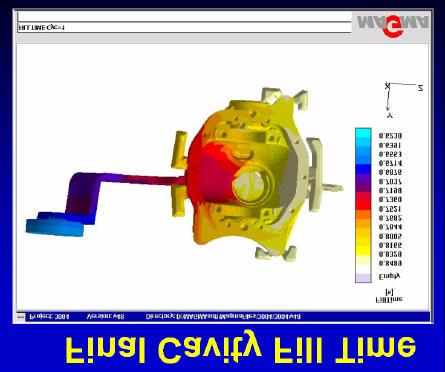
2 INITIAL GATING DESIGN EVALUATION The Port City Group s approach to gate sizing is based upon NADCA s standards for gate velocity. A gate cross sectional area of 1.32 sq. in. was established using a gate velocity comfortably between NADCA s 1200 IPS and 1800 IPS gate velocity range. A desired cavity fill time of 81 ms was determined by a simple formula that relates cavity fill time to the minimum wall thickness of the casting (1/3 minimum wall thickness (in inches) = cavity fill time (in (ms). Pour weight is lbs. The trimmed casting weighs lbs. Further calculations established that their 1200 Ton die casting machine had sufficient horsepower to displace the required amount of metal through the 1.32 sq. in. gate cross sectional area in the desired cavity fill time of 81 ms using a 4-1/2 diameter tip and a filling velocity for the shot system of 125 IPS. All of these values remained the same for the First Tool Design and the Second Tool Design. The shot profile in Figure 1 shows the injection process employed with the First Tool Design
3 The initial gating design is shown in Figure 2 below. Figure 1

4 Figure 2 All of the gating, filling, air pressure, and solidification modeling was done using the gate areas and fill times defined above. The final part has a drilled and tapped hole that is a critical area for sealing. The gating area encompasses the machined hole location on the First Tool Design. The filling simulation revealed that this area has high entrapped air, which is the result of a significant variation between the ingate thickness and the casting thickness. Further modeling using a Tracer Particle Evaluation shows the swirling effect caused by this thickness variation. See Figures 3 and 4. The MagmaSoft modeling software revealed that the air pressure in the critical machined hole area would be between 25 PSI and 40+ PSI using the gate design that was employed on the First Tool Design. From past experience, the Port City Group knew that air pressure in the casting during filling in excess of 2 atmospheres (29.4 PSI) would result in porosity in that area of the casting. It was hoped that effective intensification could reduce the problems associated with porosity in this area of the machined hole.


5 Figure 3 EVALUATION OF OTHER GATE DESIGNS Figure 4 Based upon these known problem areas in the casting, evaluation of some different gate and runner systems was deemed to be prudent. The Port City Group proceeded to model three different approaches, including splitting the gate, using a comb gate, and finally, moving the gate to the opposite side of the part. A filling simulation using a split gate was performed. The result confirmed that there would still be high air pressure in the casting, and specifically the simulation revealed that the air pressure in the area of the critical machined hole would still exceed the 2 atmosphere threshold (25 to 36 PSI was revealed in the simulation). See Figure 5.


6 Figure 5 A subsequent simulation employing a comb gate did not resolve this problem, with the air pressure in the critical area between 30 and 37 PSI (Figure 6). So, moving the gate to the opposite side of the casting was simulated. The air pressure in the critical area after moving the gate to the opposite side of the casting still exceeded the 2 atmosphere threshold (32-38 PSI) (See Figure 7). However, in this arrangement, it became possible to place a vent in this critical area which would assist with removal of the entrapped air and help to reduce the air pressure. So, it was decided to move the gate to the opposite side of the casting, and to continue with more simulations to further refine the design. Figure 6

.")
7 Figure 7 GATING OPIMIZATION Additional filling simulations were performed in order to define the best possible flow pattern that would improve the critical areas of the casting with the ingate moved to the opposite side of the casting. When considering a flow pattern, the desired location(s) of the last point to fill should be determined. (See Figure 8). Figure 8 Many different combinations of Ingate Thickness/Length/Gate Shape were simulated (See Figure 9). The best of these, designated as Final on Figure 9 was selected.

8 Figure 9 The following points summarize the progress toward the Second Tool Design: 1. High air pressure was evident in all gating designs considered. 2. Venting was not possible with a split or comb gate 3. Moving the gate to the opposite side of the casting enabled venting 4. Good overflow and vent design should mitigate air entrapment 5. Defining the desired flow pattern and final point to fill is a critical step 6. Many variations were simulated to determine the best combination of ingate width/thickness and angle of approach. 7. All gate simulations utilized the same gate area. SOFTSHOT TECHNOLOGY As previously mentioned, flashing in the slide area was the chief culprit in the premature failure of the First Tool Design by PCG. Therefore, elimination of the flashing problem was critical to establishing a robust process with a low scrap rate. The Port City Group decided upon a novel potential solution; using a carefully designed set of overflows, which when properly positioned in the die where the final filling of the casting occurs, have the potential to absorb the kinetic energy of the shot system at impact. This new technology is called SoftSHOT Technology. SoftSHOT Technology is a technical innovation that employs carefully designed overflows to (a) limit the cavity pressure at impact, (b) smoothly decelerate the shot system, and (c) because a cavity pressure has been selected that the clamp end can hold firmly closed, eliminate flash from the castings. It is critical to position the deceleration overflows where the final filling of the casting occurs. The filling and flow simulations were invaluable in determining the best location for the deceleration overflows. SoftSHOT Technology Application Software includes a mathematical model of the dynamics of the shot system and the pressure in the tooling beginning at a hypothetical position on the shot profile where the forced deceleration of the shot system begins. At this hypothetical position, it is assumed that the casting is now made, but the overflows have not yet been filled.

9 The mathematical model calculates (a) the velocity of the shot system, (b) the pressure in the runner system, (c) the pressure in the cavity area of the die, and (d) the position of the shot system, all displayed versus time on the X-axis and as a percentage of their maximum value on the Y-axis, for the appropriate time window. The model can be employed in various ways to evaluate tooling and overflow designs. For example, existing overflows on a sample tool can be input, and the model will calculate the likely result for the four factors outlined above. Changes to the overflows can be evaluated in this manner. The model can be used in an optimized format, where the user specifies a desired cavity pressure to be achieved and maintained, and then the model will calculate a set of deceleration overflows that will limit the cavity pressure to the user specified value. The SoftSHOT Technology model has some required user input fields, known as a Data File. The Data File for the 1200 Ton Prince machine and the process employed by the Port City Group for making this casting is shown in Figure 10. Figure 10 The Data File establishes the kinetic energy of the shot system at impact, in effect, quantifying the physical blow that the shot system delivers to the tooling and the clamp end of the machine. Other factors, such as the metal being cast, the number of cavities, and some volumes for the runner system are also input. The SoftSHOT Technology mathematical model can calculate, by means of an iterative process, the size of a series of deceleration overflows that will absorb the kinetic energy of the shot system at impact. Size means establishing a specific volume for each deceleration overflow, along with a specific cross sectional gate area for each overflow pocket. The gate leading to the overflow acts as a valve, and the semi -aerated, semi frozen, milk shake metal that reaches these overflow gates is the fluid crossing the valve. The valve (gate) is sized according to a flow coefficient, and the gates are designed to be inefficient. The pocket volume of each overflow determines how long each of the valves (gates leading to the overflows) are On. Flow curves for hydraulic valves (for example) plot flow across the valve (usually on the X axis) at a given pressure drop (usually on the Y axis). A typical flow curve is pictured below in Figure 11. An efficient valve will exhibit a low pressure drop at a given flow rate. An inefficient valve will exhibit a high pressure drop at a given flow rate. This same concept is behind the overflow sizing calculations.

10 Figure 11 SoftSHOT Technology calculates purposefully inefficient gates which stall out the horsepower of the shotend at the end of the shot, and at precisely the proper moment, i.e., when the die is full, having the added benefit of compensating for the dosing variation, and resulting in a more stable process. Figure 12 shows the SoftSHOT Technology prediction for the First Tool Design by PCG. The last overflow fills at approximately 4.8 ms after the casting is full. From this point forward, the relationship between plunger displacement and pressure in the tooling is linear. AT 5.7 ms after the casting is full, the plunger has come to a complete stop and the peak cavity pressure of 19,613 psi occurs. This pressure is far beyond what the clamp end of the die casting machine can hold closed. The result is that the die halves are blown apart, and in the case of the First Tool Design, the slide area is badly blown and loaded up with flash. This is the baseline SoftSHOT prediction.. Figure 12 highlights a very unfriendly situation for the tooling and the clamp end of the die casting machine. The huge impact spike delivers a powerful and unnecessary blow to the clamp end of the machine, which results in considerable wear and tear to pins, bushings, platens, linkage, etc. The shotend comes to an abrupt halt, with considerable bouncing, incurring shock and vibration to the mechanical and sensor assemblies. Figure 12


11 Figure 13 shows a casting from the First Tool Design when the tool was new. There is not much evidence of flash, which became much worse as the tool began to wear. The 1200 Ton Prince machine could not hold the die closed without the low impact system enabled. Figure 13 Figure 14 shows the SoftSHOT Technology prediction for an optimized set of overflows. The graph has been labeled to show the precise moments and positions where the bosses, overflows, and deceleration overflows are filled. The adjacent detailed image of the casting identifies the bosses, overflows, and deceleration overflows. The deceleration overflows 4, 3, 2, and 1 are responsible for decelerating the shot system smoothly and limiting the cavity pressure. These were positioned in the area of the critical machined hole, which is the final place to fill in the tool. Figure 14


12 A cavity pressure of 5500 psi was chosen for the Second Tool Design. Based upon calculations, the clamp end of the die casting machine could easily hold the tool closed at this peak cavity pressure. In comparison to the baseline situation where the calculated peak cavity pressure is 19,613 psi, the SoftSHOT Technology deceleration overflow set reduces the peak cavity pressure by 72%. The MagmaSoft modeling software was used to evaluate the filling pattern of the new tool design, as previously stated. The best location for all of the overflows was determined from these filling simulations, which showed that the greatest area of air entrapment was directly opposite the ingate. Therefore, most of the overflow volume was placed in this area. See Figure 15 (overflow placement frame). Figure 15 Furthermore, the optimum location for the deceleration overflows was determined. Several deceleration overflow orientations were modeled, as shown in Figure 16 (overflow designs). The Final overflow design (lower right hand image on Figure 16) was determined by the SoftSHOT Technology model. Figure 16

13 FINAL GATING AND OVERFLOW DESIGN Figure 17 shows the new gate placement and optimized gate design. Figure 18 also shows the final overflow placement and optimized overflow design. This final design was subjected to MagmaSoft modeling simulations, as follows: Filling Temperature Air Pressure Ingate Velocity Cavity Fill Time Final Solidification See Figures 19 through 23. Figure 17 Figure 18

14 Figure 19 Figure 20

15 Figure 21 Figure 22

16 Figure 23 Results from the modeling simulations and the SoftSHOT Technology evaluations were compared to determine whether or not any correlation or corroboration existed between the two methodologies. It was determined that the modeling done by SoftSHOT Technology and MagmaSoft do not overlap. They do, in fact, complement each other. The most applicable of the MagmaSoft simulations vis -à-vis SoftSHOT Technology is the filling simulation, because the filling simulation shows the optimum location for the placement of the deceleration overflows on castings with complicated shapes. A Fill Pressure simulation was performed for the First Tool Design and the Second Tool Design. The Fill Pressure Result for the Second Tool Design did show a much lower pressure in the area of the deceleration overflows. VERIFY SOFTSHOT TECHNOLOGY AND THE DIECASTING MACHING The process at the die casting machine was identical for the two tools. With the First Tool Design, the Port City Group could not hold metal without employing the low impact system on the die casting machine. The calculated peak cavity pressure was 19,613 psi. From the shot profile, the head side pressure at impact was 3100 psi. The tool was scrapped at 82% of projected tool life. (Reference Figure 1) The Second Tool Design was run successfully with the low impact system turned off. The calculated peak cavity pressure was 5499 psi. The head side pressure at imp act showed a value of 2100 psi. (See Figure 26). The tool life at the time of the preparation of this paper was 130% of the original anticipated die life, and the tool is still in very good condition and will run many more castings.

17 Figure 24 SUMMARY Moving the gate to the opposite side of the casting and optimizing the gate shape produced a favorable filling pattern that reduced the trapped air in the casting. Overflow and vent placement is critical to reduce the amount of trapped air, and refinement of the overflows and their placement did reduce air entrapment. The air pressure in the area of the machined hole was reduced to a level below the 2 atmosphere threshold. The low impact system on the die casting machine was turned off for the Second Tool Design, thereby reducing process variation. The impact pressure spike at the end of the filling process was observed to be approximately 30% lower than with the low impact system enabled when running the First Tool Design. Impact Force reduction is much friendlier to the die casting machine and the tooling. And finally, tool life has been substantially extended by reducing the peak cavity pressure by 72% using the specially designed overflow set calculated by the SoftSHOT Technology model. ACKNOWLEDGEMENTS The engineering team at Port City Group is able and nimble. They were energetic and intellectually curious, and very committed to seek new solutions to difficult casting problems. They were, and are, a progressive team to work with.
All About Die Casting
 All About Die Casting FAQ Introduction Die casting is a versatile process for producing engineered metal parts by forcing molten metal under high pressure into reusable steel molds. These molds, called
Metal Mould System 1. Introduction
 Metal Mould System 1. Introduction Moulds for these purposes can be used many times and are usually made of metal, although semi-permanent moulds of graphite have been successful in some instances. The
Complete Simulation of High Pressure Die Casting Process
 Complete Simulation of High Pressure Die Casting Process Matti Sirviö VTT Industrial Systems, Conrod Team, P.O.Box 1702, FIN-02044 VTT, Finland Tel: +358 9 456 5586, Fax: +358 9 460 627, Matti.Sirvio@vtt.fi,
HILMA Quick Tool Change for Forging Applications
 HILMA Quick Tool Change for Forging Applications Upper tool is seated in pocket of the master die set clamped with Hilma Wedge Clamps Lower tool is clamped with vertical clamping bars locked in place with
CHAPTER5 5 ZERO DEFECT MANUFACTURING IN THE PRODUCTION OF IMPELLER THROUGH THE APPLICATION OF CAD / CAE
 33 CHAPTER5 5 ZERO DEFECT MANUFACTURING IN THE PRODUCTION OF IMPELLER THROUGH THE APPLICATION OF CAD / CAE 5.1 INTRODUCTION In the first place of research, CAD/CAE was applied to achieve ZERO DEFECT MANUFACTURING
Taking MIM Tooling To the Next Level. Originally published in The American Mold Builder Magazine, February 2014
 Taking MIM Tooling To the Next Level Originally published in The American Mold Builder Magazine, February 2014 1 Metal injection molding (MIM) merges two established technologies, plastic injection molding
Computer-aided Casting Method Design, Simulation and Optimization
 Silver Jubilee Seminar Institute of Indian Foundrymen (Indore Chapter), 13 March 2008, Indore Computer-aided Casting Method Design, Simulation and Optimization Dr. B. Ravi, Professor Mechanical Engineering
Engineering & Design: Coordinate Dimensioning
 s e c t i o n Section Contents NADCA No. Format Page Frequently Asked Questions (FAQ) -2 1 Introduction -2 2 Section Objectives -3 3 Standard and Precision Tolerances -3 4 Production Part Technologies
The Design of Gating System 2. Introduction to the gating system
 MME 345 Lecture 14 The Design of Gating System 2. Introduction to the gating system Ref: [1] P. Beeley, Foundry Technology, Butterworth-Heinemann, 2001 [2] J. Campbell, Castings, Butterworth-Heinemann,
Permanent Mold Casting Processes. Assoc Prof Zainal Abidin Ahmad Department of Manufacturing & Ind. Eng.
 Assoc Prof Zainal Abidin Ahmad Department of Manufacturing & Ind. Eng. Universiti Teknologi Malaysia Permanent Mold Casting Processes Gravity die casting Pressure die casting Low pressure High pressure
4.1.3: Shell Casting.
 4.1.3: Shell Casting. It is another expandable mold casting type; Shell molding is a casting process in which the mold is a thin shell (typically 9mm) made of sand held together by a thermosetting resin
Design of table bush Die and Development of G and M Codes for Plastic Injection Hand Molding Machine
 Design of table bush Die and Development of G and M Codes for Plastic Injection Hand Molding Machine Dr. V.Vijendra kumar; Department of Mechanical engineering, M.S.Engineering College, Abhinandan KS;
Injection moulding. Introduction. Typical characteristics of injection moulded parts
 Injection moulding Introduction Injection molding is generally used to produce thermoplastic polymers. It consists of heating of thermo plastic materials until it melts and then injecting into the steel
Address for Correspondence
 Research Paper USING FLOW SIMULATION AS A TOOL FOR DEPLOYING ANALYTICAL METHODOLOGY TO DETERMINE THE MOST SUITABLE PARAMETERS FOR DESIGN FOR A DIE CASTING DIE 1 Swati Sambhajirao Patil (Sathe), 2 D.G.Kumbhar,
Integrating Product Optimization and Manufacturability in Graduate Design Course
 Session 2525 Integrating Product Optimization and Manufacturability in Graduate Design Course Mileta M. Tomovic Purdue University Abstract As CAD/FEA/CAM software tools are becoming increasingly user friendly
B.1 Die Solder Reduction
 B.1 Die Solder Reduction Patrick Hogan (MS Candidate Industrial Intern) Advisors: Diran Apelian, Joe Bigelow Sponsored by Contech LLC Introduction Die soldering is a die casting processing problem, which
Engineering & Design: Coordinate Dimensioning
 SECTION Section Contents NADCA No. Format Page Frequently Asked Questions (FAQ) -2 1 Introduction -2 2 Section Objectives -3 3 Standard and Precision Tolerances -3 4 Production Part Technologies -4 5 Die
The optimization of working cycles for HPDC technology
 ARCHIVES of FOUNDRY ENGINEERING Published quarterly as the organ of the Foundry Commission of the Polish Academy of Sciences ISSN (1897-3310) Volume 10 Issue Special1/2010 441-446 87/1 The optimization
Metal Casting Dr. D. B. Karunakar Department of Mechanical and Industrial Engineering Indian Institute of Technology, Roorkee
 Metal Casting Dr. D. B. Karunakar Department of Mechanical and Industrial Engineering Indian Institute of Technology, Roorkee Module - 02 Sand Casting Process Lecture 14 Design Of Gating System-I Good
Mold Design. 5. Mold Structure. Bong-Kee Lee School of Mechanical Engineering Chonnam National University
 5. Mold Structure Bong-Kee Lee Chonnam National University the simplest and most reliable design has the fewest number of moving parts and is more straightforward to manufacture and run in production is
MN Modelling Objects and Creating Manufacturing Strategy
 Abstract This document and the accompanying files describe the process of modelling a bell housing jig using the 3D software Catia V5. The manufacturing process by which the bell housing would be created
Design of Singe Impression Injection Mould for Lower Bearing Cover
 Design of Singe Impression Injection Mould for Lower Bearing Cover Vishwanath DC Student, M. Tech Government Tool Room and Training Centre Mysuru, India Abstract Injection moulding is one of the techniques
Gating Design Optimization for Improvement in Yield of Casting
 Gating Design Optimization for Improvement in Yield of Casting M. N. Jadhav 1, K. H. Inamdar 2 P.G. Student, Department of Mechanical Engineering, Walchand College of Engineering, Sangli, Maharashtra,
MUELLER E-5TM. and D-5TM. Drilling Machines. Reliable Connections. E-5 General Information 2. D-5 General Information 3. Operating Instructions 4-5
 operation Instructions manual MUELLER E-5TM and D-5TM TAble of contents PAGE E-5 General Information 2 Drilling Machines D-5 General Information 3 Operating Instructions 4-5 E-5 Parts 6 D-5 Parts 7! WARNING:
7 WAYS TO IMPROVE YOUR DIE CAST COMPONENTS
 www.dynacast.com 7 WAYS TO IMPROVE YOUR DIE CAST COMPONENTS Design for manufacturing (DFM) is a core methodology that ensures your die cast parts perform to specification and require the minimum of secondary
Die Life Checklist. Part Consideration. Critical to Function & Cosmetic. Cosmetic, No Function. Critical to Function. Not Critical but Functional
 Tooling for Die Casting NADCA T-2-2-00 Guidelines Guidelines to increase die life are as follows: Before the start of tooling 1) Redesign of part to reduce or eliminate sharp internal corners or features
Mid term Review Questions P a g e 1 CASTING
 Mid term Review Questions P a g e 1 Q1: Define the casting process? CASTING A1: Casting is the process of pouring molten metal into a mould containing a cavity, which represents the required product shape
CHAPTER 5: MOULDING PROCESS
 CHAPTER OUTLINE CHAPTER 5: MOULDING PROCESS 5.1 INTRODUCTION 5.2 INJECTION MOULDING 5.3 COMPRESSION AND TRANSFER MOLDING 5.4 BLOW AND ROTATIONAL MOLDING 5.5 PRODUCT DESIGN CONSIDERATIONS 1 5.1 Introduction
Processing of Non- Metals Dr. Inderdeep Singh Department of Mechanical and Industrial Engineering Indian Institute of Technology, Roorkee
 Processing of Non- Metals Dr. Inderdeep Singh Department of Mechanical and Industrial Engineering Indian Institute of Technology, Roorkee Module - 4 Plastics: properties and processing Lecture - 7 Rotational
RJG Mold Deflection Sensor Installation and Use
 when mold is open RJG Mold Deflection Sensor Installation and Use RJG s Mold Deflection sensor measures how much the mold parting line has opened on each cycle. The sensor mounts in the clamp plate with
Guideline. Casting Selection Process. Table of Contents. Delivery Engineered Solutions
 Casting Selection Process Guideline Table of Contents Introduction... 2 Factors In Choosing A Process... 2 Category Details & Requirements... 4 Sand casting... 4 Gravity die casting (also known as permanent
MOLDING LARGE SCALE MODEL TIRES
 JRH SCALE CARS www.jrhscalecars.com MOLDING LARGE SCALE MODEL TIRES Introduction One of the challenges in scratch-building scale models is making appropriate tires. Properly sized, properly scaled, historically
A White Paper on Danley Sound Labs Tapped Horn and Synergy Horn Technologies
 Tapped Horn (patent pending) Horns have been used for decades in sound reinforcement to increase the loading on the loudspeaker driver. This is done to increase the power transfer from the driver to the
Extrusion. Process. The photo below shows a typical thermoplastic extruder.
 Extrusion This process can be compared to squeezing toothpaste from a tube. It is a continuous process used to produce both solid and hollow products that have a constant cross-section. E.g. window frames,
Special Casting Process. 1. Permanent mould casting
 Special Casting Process 1. Permanent mould casting A permanent mold casting makes use of a mold or metallic die which is permanent.molten metal is poured into the mold under gravity only and no external
Gating Manual NORTH AMERICAN DIE CASTING ASSOCIATION. Publication # 512
 Gating Manual NORTH AMERICAN DIE CASTING ASSOCIATION Publication # 512 Although great care has been taken to provide accurate and current information, neither the author(s) nor the publisher, nor anyone
Digital Technology in the Wax Room
 Digital Technology in the Wax Room EICF Hungry Digital Technology for Quality Assurance 24 th 25 th September 2012 Bruce Phipps President, MPI, Inc. Digital Technology in the Wax Room Trip down Memory
Molded Parts and Mold Design
 Molded Parts and Mold Design July 29, 2009 Introduction Importance of Proper Mold Design Design Considerations Overview of Design Process SolidWorks & Mold Design Overview of Mold Design Most common method
OPTIMIZATION OF MULTIGATE RUNNER IN LONG CASTINGS: A SIMULATION APPROACH
 913 OPTIMIZATION OF MULTIGATE RUNNER IN LONG CASTINGS: A SIMULATION APPROACH IRFAN AHMAD ASARI (Mechanical engineering department Aligarh Muslim University, Aligarh U.P Email: mechirfaan@gmail.com) The
Fisher 667 Diaphragm Actuator Sizes 30/30i 76/76i and 87
 Instruction Manual 667 Actuator (Size 30/30i - 76/76i and 87) Fisher 667 Diaphragm Actuator Sizes 30/30i 76/76i and 87 Contents Introduction... 1 Scope of Manual... 1 Description... 2 Specifications...
Chapter 1 Sand Casting Processes
 Chapter 1 Sand Casting Processes Sand casting is a mold based net shape manufacturing process in which metal parts are molded by pouring molten metal into a cavity. The mold cavity is created by withdrawing
OPTIMIZATION OF CASTING TECHNOLOGY OF THE PRESSURE DIE CAST AZ91D MG-BASED ALLOY
 METALLURGY AND FOUNDRY ENGINEERING Vol. 36, 2010, No. 2 Grzegorz Piwowarski*, Witold K. Krajewski***, Janusz Lelito** OPTIMIZATION OF CASTING TECHNOLOGY OF THE PRESSURE DIE CAST AZ91D MG-BASED ALLOY 1.
Materials & Processes in Manufacturing
 Materials & Processes in Manufacturing ME 151 Chapter 15 Multiple Use Mold Casting Processes 1 Introduction Expendable Molds - melting point materials and castings General shortcomings of the expendable-mold
BMM3643 Manufacturing Processes Metal Casting Processes (Sand Casting)
") BMM3643 Manufacturing Processes Metal Casting Processes (Sand Casting) by Dr Mas Ayu Bt Hassan Faculty of Mechanical Engineering masszee@ump.edu.my Chapter Synopsis This chapter will expose students to
BMM3643 Manufacturing Processes Metal Casting Processes (Sand Casting) by Dr Mas Ayu Bt Hassan Faculty of Mechanical Engineering masszee@ump.edu.my Chapter Synopsis This chapter will expose students to
Drilled Rail Lubrication
 APTA Rail Conference June 23, 2015 SKF Lincoln Lubrication Systems St Louis, MO Presented by Drew Welch Completed by Paul Conley Drew Welch SKF North American Railroad Specialist Drew Welch is the North
SHAPED BY INNOVATION.
 SHAPED BY INNOVATION www.fishercast.com Engineering the best value At FisherCast Global, we are committed to engineering cost-effective, innovative manufacturing solutions for your small component production
Stargrip series 3000 Mechanical Joint Wedge Action Restraint for Ductile Iron Pipe
 Stargrip series 3000 Mechanical Joint Wedge Action Restraint for Ductile Iron Pipe INFORMATION The Stargrip Mechanical Joint Restraint System is a unique product with a proven design that provides an exceptional
Operating & Maintenance Instructions 320 Dome Blowing Unit
 Operating & Maintenance Instructions 320 Dome Blowing Unit Table of Contents 1. On Delivery... 2 2. General Information... 3 3. Dome Blowing Technique... 4 4. Other Shapes... 6 5. Machine Maintenance...
Injection moulding BUDAPEST UNIVERSITY OF TECHNOLOGY AND ECONOMICS FACULTY OF MECHANICAL ENGINEERING DEPARTMENT OF POLYMER ENGINEERING
 B3 BUDAPEST UNIVERSITY OF TECHNOLOGY AND ECONOMICS FACULTY OF MECHANICAL ENGINEERING DEPARTMENT OF POLYMER ENGINEERING Injection moulding INJECTION MOULDING OF THERMOPLASTICS WWW.PT.BME.HU LOCATION OF
UTILIZING FLOW SIMULATION IN THE DESIGN PHASE OF A DIE CASTING DIE TO OPTIMIZE DESIGN PARAMETERS
 UTILIZING FLOW SIMULATION IN THE DESIGN PHASE OF A DIE CASTING DIE TO OPTIMIZE DESIGN PARAMETERS WHILE VALIDATING THROUGH EXPERIMENTATION DURING TRIALS 1 P.R.Vispute, 2 D.S.Chaudhari, 3 Swapnil Kulkarni
The Use of In-Cavity Data for LSR Applications
 The Use of In-Cavity Data for LSR Applications Mike Groleau, RJG Inc. Greg Roembke, Roembke Mfg. & Design, Inc. Introduction As liquid silicone molding applications continue to grow, we see increasing
Operating & Maintenance Instructions 25 Injection Moulding Machine
 Operating & Maintenance Instructions 25 Injection Moulding Machine Table of Contents 1. Health and Safety Information... 2 2. Upon Receipt... 2 3a. Temperature Controller Settings (Brainchild Controller)...
Carbide Doctor Blades on Ceramic Press Rolls
 Carbide Doctor Blades on Ceramic Press Rolls Mohan Jayaraman R&D Team Leader Kadant Web Systems Inc. Paul Haller Former Ceramic Roll Product Manager Voith North America Gregory L. Wedel President Kadant
Machining Titanium. Losing the Headache by Using the Right Approach (Part 2)
") Machining Titanium Losing the Headache by Using the Right Approach (Part 2) Author Biography Brian List Research & Development Team Leader Brian List currently leads the research and development group
Machining Titanium Losing the Headache by Using the Right Approach (Part 2) Author Biography Brian List Research & Development Team Leader Brian List currently leads the research and development group
Solidification Process(1) - Metal Casting Chapter 9,10
 - Metal Casting Chapter 9,10") Solidification Process(1) - Metal Casting Chapter 9,10 Seok-min Kim smkim@cau.ac.kr -1- Classification of solidification processes -2- Casting Process in which molten metal flows by gravity or other force
Solidification Process(1) - Metal Casting Chapter 9,10 Seok-min Kim smkim@cau.ac.kr -1- Classification of solidification processes -2- Casting Process in which molten metal flows by gravity or other force
Module 3 Selection of Manufacturing Processes
 Module 3 Selection of Manufacturing Processes Lecture 4 Design for Sheet Metal Forming Processes Instructional objectives By the end of this lecture, the student will learn the principles of several sheet
Zero Defect Manufacturing and Hot Runner Balancing based on Cavity Pressure Measurements
 Proplast Kistler / Bt 2009 / 14th / Srr April 24 Sept 200809 29. September 2009 1 Zero Defect Manufacturing and Hot Runner Balancing based on Cavity Pressure Measurements Dr.-Ing Oliver Schnerr Head of
Clamping Tools The most effective clamping tool for individual applications an overview.
 05/2012 Clamping Tools The most effective clamping tool for individual applications an overview. By Thomas Oertli There is no best clamping tool. However, we have developed the most effective and therefore
The jigs and fixtures are the economical ways to produce a component in mass production system. These are special work holding and tool guiding device
 The jigs and fixtures are the economical ways to produce a component in mass production system. These are special work holding and tool guiding device Quality of the performance of a process largely influenced
1500HD Assembly & Operation Manual 1500 lb. Capacity Motorcycle Lift
 1500HD Assembly & Operation Manual 1500 lb. Capacity Motorcycle Lift 1500HD Assembly Instructions Assembly 1. Remove the lift and all parts from the wooden crate 2. Remove the pump from the cardboard box
Manufacturing Processes - I Dr. D. B. Karunakar Mechanical and Industrial Engineering Department Indian Institute of Technology, Roorkee
 Manufacturing Processes - I Dr. D. B. Karunakar Mechanical and Industrial Engineering Department Indian Institute of Technology, Roorkee Module - 2 Lecture - 7 Metal Casting Good morning. We have been
Operating, Servicing, and Safety Manual Model # 100 Standard Hydraulic Tubing Notcher Model #100-U Heavy Duty Hydraulic Tubing Notcher
 Operating, Servicing, and Safety Manual Model # 100 Standard Hydraulic Tubing Notcher Model #100-U Heavy Duty Hydraulic Tubing Notcher Model # 100 Standard Model #100-U Heavy Duty CAUTION: Read and Understand
SFSA T&O Conference 2017
 Air Entrainment: testing the model. Joe Plunger, President/Owner Midwest Metal Products, Inc (MMP) Acknowledgements and thanks for their considerable contributions to this work: Dave Poweleit, Christoph
Vacuum Casting in the Loughborough Design School
 Vacuum Casting in the Loughborough Design School A Guide for Final Year Students Dr. Richard Bibb Selecting Vacuum Casting for Student Projects Vacuum casting can be an excellent way of creating complex
Jürgen Wüst October 2008
 Visi-Trak supplies process automation solutions for improving manufacturing quality and profits. Help Our Customers Differentiate themselves in today s competitive environment. Make better decisions, better
Phased Array Velocity Sensor Operational Advantages and Data Analysis
 Phased Array Velocity Sensor Operational Advantages and Data Analysis Matt Burdyny, Omer Poroy and Dr. Peter Spain Abstract - In recent years the underwater navigation industry has expanded into more diverse
Heat and Flow Analysis of High Pressure Die Casting using ProCAST
 Heat and Flow Analysis of High Pressure Die Casting using ProCAST Nagaraj R 1, Asst. Prof. V.A.Girisha 2, Gayathri R 3 1 Mechanical Engineering, R V college of Engineering, Bangalore 560059 India, Email
Lecture - 05 Thermoforming Processes
 Processing of Polymers and Polymer Composites Dr. Inderdeep Singh Department of Mechanical and Industrial Engineering Indian Institute of Technology, Roorkee Lecture - 05 Thermoforming Processes Namaskar
Addressing Tooling and Casting Requirements at the Design Stage. Whitepaper. Bhaskar Sinha
 Addressing Tooling and Casting Requirements at the Design Stage Whitepaper Bhaskar Sinha Contents Abstract... 2 Introduction... 2 Casting Guidelines... 2 Wall Thickness... 2 Mold Wall thickness... 3 Ribs...
SAFETY PRECAUTIONS GENERAL INFORMATION
 Form No. 102831 SPX Corporation 5885 11th Street Rockford, IL 61109-3699 USA Internet Address: http://www.hytec.com Tech. Services: (800) 477-8326 Fax: (800) 765-8326 Order Entry: (800) 541-1418 Fax: (800)
Wire EDM Fundamentals
 2 Wire EDM Fundamentals Revolutionizing Machining 35 Wire Electrical Discharge Machining (EDM) is one of the greatest innovations affecting the tooling and machining industry. This process has brought
Published by: BOY Machines, Inc. news
 news Published by: BOY Machines, Inc. January 2018 Spritzgiessautomaten Editorial 25 Years Fakuma Friedrichshafen, Germany The Fakuma is the largest Exhibition worldwide dedicated nearly exclusively in
Eliminate Corrosion & Electrolysis Forever!
 Eliminate Corrosion & Electrolysis Forever! SIMSITE Rings Casing Rings and Wear Rings Corrosion Resistant Light Weight Prevents Electrolysis Prevents Damage to the Casing Non-Sparking Non-Galling Allows
A customer requiring anonymity was able to procure the casting it needed at a lower cost and lead time than its previous fabrication.
 Rapid Tooling Opens New Diecasting Doors Think diecasting tooling will ruin your lead times? Think again. North American Die Casting Association, Wheeling, Illinois Manufacturers seeking a competitive
VERSAtoolTM SAE J533 & SAE J1453. Safety and Operating Manual
 VERSAtoolTM Mechanically Assisted / Manual Tube End Flare & Flange Machine SAE J533 & SAE J1453 Safety and Operating Manual I. Safety Instructions................................. Page 2 II. Specifications.....................................
In the foundry. (continued)
") In the foundry Me by a vertical squeeze-caster - an Ube 350T model used to cast Aluminium. I was involved in refining the conditions used with this machine, in order to get fully-sound castings at large
In the foundry Me by a vertical squeeze-caster - an Ube 350T model used to cast Aluminium. I was involved in refining the conditions used with this machine, in order to get fully-sound castings at large
INSTALLATION MANUAL IOWA MOLD TOOLING CO., INC. BOX 189, GARNER, IA MANUAL PART NUMBER:
 PARTS-1 Model 24562/28562 Crane INSTALLATION MANUAL IOWA MOLD TOOLING CO., INC. BOX 189, GARNER, IA 50438-0189 641-923-3711 MANUAL PART NUMBER: 99903701 Iowa Mold Tooling Co., Inc. is an Oshkosh Truck
OPERATING MANUAL SHOCK TOOL OWS WENZEL DOWNHOLE TOOLS LTD.
 OPERATING MANUAL SHOCK TOOL OWS WENZEL DOWNHOLE TOOLS LTD. Release Notes: Release 2 Issued May 2016 Document # OM ST 001, Shock Tool Operating Manual Reviewed By: RG 1 P age OPERATING MANUAL SHOCK TOOL
Clocking a TD-04 Turbo Compressor Housing. Appendix A : AWIC Silicone and Tubing Fitting
 Clocking a TD-04 Turbo Compressor Housing Appendix A : AWIC Silicone and Tubing Fitting Revision A: 7-13-2015 Tools: Metric Sockets (10, 12, 14, 17mm) 5mm Hex Key Large Internal Snap Ring Pliers 3/8 Socket
APPLICATION OF NUMERICAL SIMULATION ON CAST- STEEL TOOTHED PLATE
 Engineering Review, Vol. 34, Issue 1, 1-6, 2014. 1 APPLICATION OF NUMERICAL SIMULATION ON CAST- STEEL TOOTHED PLATE M. Guofa L. Changyun G. Zeng * School of Materials Science and Engineering, Henan Polytechnic
WIRE ROPE LUBRICATING SYSTEM
 PROVIDES FAST AND EFFECTIVE CLEANING AND LUBRICATION OF WIRE ROPES BY FORCING QUALITY LUBRICANT UNDER HIGH PRESSURE TO THE CORE OF THE WIRE ROPE WIRE ROPE LUBRICATING SYSTEM 13 TS BENEFITS: Lightweight,
Geometric Dimensioning and Tolerancing
 Geometric Dimensioning and Tolerancing (Known as GDT) What is GDT Helps ensure interchangeability of parts. Use is dictated by function and relationship of the part feature. It does not take the place
Hands On. 6 Here, three pieces of thermoplastic are cut to the designated die size. I make one layer of the die at a time.
 Hands On Jan s method of creating die forms is both effective and fascinating. Her demonstration includes essential information, such as constructing a well-made die, forming metal with the hydraulic press,
Operators Manual: Diamond Rock Saw Excavator Attachment Austramac Flashcut Series
 Operators Manual: Diamond Rock Saw Excavator Attachment Austramac Flashcut Series! WARNING! Inappropriate use of rock saw may cause serious injury or death. Operators must read this manual before use and
VIRTUAL PROTOTYPING APPROACH FOR THE DESIGN OF DIECAST FURNITURE COMPONENTS
 VIRTUAL PROTOTYPING APPROACH FOR THE DESIGN OF DIECAST FURNITURE COMPONENTS Carlo Magistretti - B&B Italia S.p.A. Noverdate, Italy Nicola Gramegna - EnginSoft s.r.l. Padova, Italy ABSTRACT B&B ITALIA is
CIRRUS AIRPLANE MAINTENANCE MANUAL
 FASTENER AND HARDWARE GENERAL REQUIREMENTS 1. DESCRIPTION This section contains general requirements for common hardware installation. Covered are selection and installation of cotter pins, installation
RG Connector (Molded Mating Extension Cable Required) A H B G. MS Connector (Mating Connector: P/N ; MS3116F-12-10S or Extension Cable)
 A H B G. MS Connector (Mating Connector: P/N ; MS3116F-12-10S or Extension Cable)") T E M P O S O N I C S L S E R I E S INSTALLATION A N A L O G O U T P U T 550570 B W I R I N G - A N A L O G O U T P U T S RG Connector: (Voltage or Current Output) 1 Gray 0 to 10 Vdc, 4 to 20 ma, or 0
T E M P O S O N I C S L S E R I E S INSTALLATION A N A L O G O U T P U T 550570 B W I R I N G - A N A L O G O U T P U T S RG Connector: (Voltage or Current Output) 1 Gray 0 to 10 Vdc, 4 to 20 ma, or 0
Hands On. 6 Here, three pieces of thermoplastic are cut to the designated die size. I make one layer of the die at a time.
 Hands On Jan s method of creating die forms is both effective and fascinating. Her demonstration includes essential information, such as constructing a well-made die, forming metal with the hydraulic press,
Application of Lean Six-Sigma Methodology to Reduce the Failure Rate of Valves at Oil Field
 , 22-24 October, 2014, San Francisco, USA Application of Lean Six-Sigma Methodology to Reduce the Failure Rate of Valves at Oil Field Abdulaziz A. Bubshait, Member, IAENG and Abdullah A. Al-Dosary Abstract
UNDERSTANDING THE IMPORTANCE OF PUNCH LENGTH AND CUP DEPTH
 WHITEPAPER UNDERSTANDING THE IMPORTANCE OF PUNCH LENGTH AND CUP DEPTH { Manufacturing tablets to a uniform hardness, weight, and thickness requires tablet press punches of consistent length. We will describe
Residential & Industrial Fence
 Residential & Industrial Fence Assembly Instructions CONTENTS 02: OVERVIEW & CONTENTS 03: PRODUCT SPECIFICATIONS 04: GETTING STARTED 05: WALL ATTACHMENT & LINE POST ASSEMBLY 06: CORNER POST ASSEMBLY 07:
Processing of Non-Metals Prof. Dr. Inderdeep Singh Department of Mechanical and Industrial Engineering Indian Institute of Technology, Roorkee
 Processing of Non-Metals Prof. Dr. Inderdeep Singh Department of Mechanical and Industrial Engineering Indian Institute of Technology, Roorkee Module - 4 Plastics: Properties and Processing Lecture - 5
-binary sensors and actuators (such as an on/off controller) are generally more reliable and less expensive
 are generally more reliable and less expensive") Process controls are necessary for designing safe and productive plants. A variety of process controls are used to manipulate processes, however the most simple and often most effective is the PID controller.
Process controls are necessary for designing safe and productive plants. A variety of process controls are used to manipulate processes, however the most simple and often most effective is the PID controller.
Butterfly Leaf Dining Table Plans
 Butterfly Leaf Dining Table Plans Part 1 An attractive dining table with a secret: the leaf folds and stores inside the table. Season 1, Episode 7 P a g e 2 I first saw a butterfly leaf table in a back
Gastrow Injection Molds
 Paul Unger (Ed.) Gastrow Injection Molds Sample Chapter 1: Principles of Mold Design ISBNs 978-1-56990-402-2 1-56990-402-2 HANSER Hanser Publishers, Munich Hanser Publications, Cincinnati 1.1 Types of
- sprue gate - pinpoint gate - fan gate - tunnel gate
 Moulds for processing of thermosetting moulding compounds 1. Sprue and Runner Systems and Gates Sprues should have either a round cross-section or a rounded trapezoidal construction and must have well-polished
Exploration of a Student Project in a Materials Processing Course
 Paper ID #8093 Exploration of a Student Project in a Materials Processing Course Prof. Somnath Chattopadhyay, Georgia Southern University c American Society for Engineering Education, 2013 EXPLORATION
Instructions for the BNC CNC Mill and the dxf2fgc Conversion Program
 1 Introduction Instructions for the BNC CNC Mill and the dxf2fgc Conversion Program Eric Chu Mathies Group, UC Berkeley May 21, 2009 If you're reading this to learn how to use the BNC s CNC mill and you
Numerical Optimization of Grey C.I. Casting using Simulation
 IOSR Journal of Mechanical and Civil Engineering (IOSR-JMCE) e-issn: 2278-1684,p-ISSN: 2320-334X PP. 47-51 www.iosrjournals.org Numerical Optimization of Grey C.I. Casting using Simulation M. N. Jadhav,